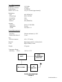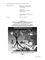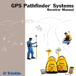
1
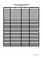
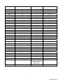
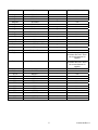
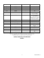
PRODUCT
SUPPORT
MANUAL
Y1-03-0169
Rev. A
406 PLB
Product No. 2792
GyPSIÔ 406 PLB
(with GPS Interface)
Product No. 2793
Model PLB-100
Personal Locator Beacon
ACR Electronics, Inc.
5757 Ravenswood Road
Fort Lauderdale, Fl 33312
+1(954) 981-3333 · Fax +1 (954) 983-5087
www.acrelectronics.com
Email: [email protected]
A Chelton Group company
* * * WARNING * * *
THIS TRANSMITTER IS AUTHORIZED FOR USE ONLY
DURING SITUATIONS OF GRAVE AND IMMINENT DANGER
DELIBERATE MISUSE MAY RESULT IN A SEVERE PENALTY
Advice to owners of Personal Locator Beacons (PLBs)
Registration of 406 MHz satellite PLB with the PLB Registration Section of the national authority* is mandatory
because of the global alerting nature of the system.
The information provided in the Registration Card is used only for rescue purposes and will greatly assist in any
beacon alarm incident.
Fill in the owner registration card immediately upon completion of the sales transaction. Mail the Registration Card
immediately.
If the beacon is to enter service immediately, complete the Registration Card and fax the information to the national
authority. The original card must still be mailed to the national authority* for hard-copy reference and filing.
If the current owner is transferring the beacon to a new owner, the current owner is required to inform the national
authority* by letter, facsimile or telephone, of the name and address of the new owner.
The subsequent owner of the beacon is required to provide the national authority* with the information as shown
on the owner Registration Card. Additional Registration Cards may be obtained by contacting ACR or the
appropriate national authority.
THIS OBLIGATION TRANSFERS TO ALL SUBSEQUENT OWNERS.
*National Authority
The term “national authority” appears throughout this manual. Wherever these words appear, reference is made to
the government body responsible for PLB registration for the country in which the unit is registered. The addresses
for various national authorities can be found on the Registration Card.
The National authority in the United States is the national oceanic and atmospheric administration.
The address is:
SARSAT Beacon Registration
NOAA/NESDIS
E/SP3, Rm 3320, FB-4
5200 Auth Road
Suitland, Md 20746-4304
www.sarsat.noaa.gov
Tel No. (301) 457-5430
Fax No. (301) 568-8649
The national authority in Canada is the NSS (National Search & Rescue Secretariat)
Canadian personal emergency beacon registry.
The NSS Telephone Number is:
(613) 996-1504
(800) 727-9414
i
Y1-03-0169 Rev. A
TABLE OF CONTENTS
SECTION 1 - THE SYSTEM
1.1
General .................................................................................................................................. 1
1.2
Purpose.................................................................................................................................. 1
1.3
Satellite Detection ................................................................................................................. 2
1.4
Authorizations ....................................................................................................................... 4
1.5
Characteristics ....................................................................................................................... 4
1.6
Technical Data ...................................................................................................................... 4
1.6.1 Applicable Documents .......................................................................................................... 4
1.6.2 Specifications ........................................................................................................................ 4
SECTION 2 - OPERATION
2.1
General .................................................................................................................................. 10
2.2
GyPSI™ 406 PLB Operating Instructions ............................................................................ 10
2.2.1 Activation.............................................................................................................................. 10
2.2.2 Deactivation .......................................................................................................................... 10
2.2.3 Self Test ................................................................................................................................ 10
SECTION 3 - EXTERNAL GPS I/R ADAPTER
3.1
General .................................................................................................................................. 12
3.2
GPS Adapter ......................................................................................................................... 12
3.2.1 Connecting ............................................................................................................................ 12
3.2.2 Setup...................................................................................................................................... 13
3.2.3 Testing................................................................................................................................... 13
3.2.4 Position data set to default .................................................................................................... 14
4.0
5.0
6.0
7.0
MAINTENANCE ................................................................................................................ 14
FREQUENTLY ASKED QUESTIONS............................................................................ 14
REGISTRATION................................................................................................................ 16
FALSE ALARMS ............................................................................................................... 16
Figure 1 - GEOSAR Satellite Coverage............................................................................................ 3
Figure 2 - SAR Satellite Coverage .................................................................................................... 3
Figure 3 - PLB Block Diagram......................................................................................................... 5
Figure 4 - Known Compatible GPS Receiver's................................................................................. 6-9
Figure 5 - Self test ............................................................................................................................. 11
Figure 6 - Operating Position........................................................................................................... 12
Figure 7 - GPS Adapter Illustration ................................................................................................. 13
Figure 8 - External GPS I/R Cable ................................................................................................... 14
Figure 9 - Basic Concept of the (COSPAS-SARSAT) System ........................................................... 17
ii
Y1-03-0169 Rev. A
SECTION 1 - THE SYSTEM
1.1
GENERAL
1.1.1 This manual provides operation and maintenance instructions for the 406 Personal Locator
Beacon, Product No. 2792 and the GyPSI™ 406 Personal Locator Beacon, Product No. 2793
hereinafter referred to as the PLB. This section describes the characteristics and details of the 406
PLB and GyPSI™ 406 PLB Systems.
1.2
PURPOSE
1.2.1 The PLB provides distress alerting via radio transmission on 406 MHz to satellites of the
COSPAS-SARSAT network. The GyPSI™ PLB can also transmit a distress alert to the
GEOSAR network that includes GPS latitude and longitude coordinates that are inputted through
an I/R Interface that connects to the data output of a GPS Receiver.
1.2.2 The message transmitted by the PLB is unique for each beacon, which provides identification of
the transmitter through computer access of registration files maintained by the National Search
and Rescue Secretariat or other national authority. It is the user's responsibility to fill out and
mail the enclosed registration form to the appropriate agency of the country under which
the PLB is registered. The PLB is programmed by ACR during manufacture and can be
reprogrammed by an ACR authorized programming facility for the registered country.
Remember, if your PLB is not registered, SAR Authorities do not know who you are, where you
live or where to contact anyone who might know anything about your situation.
1.2.3 Once Search and Rescue (SAR) forces are alerted by the PLB signal (406 MHz), relayed through
the COSPAS-SARSAT and/or GEOSAR network, they can converge on the position estimated by
the satellite. When GyPSI™ PLB GPS interface is used SAR authorities can know your precise
location and speed up reaction time. Intermediate and short range location is aided by the PLB
with its on board radio beacon homing signal transmitter (121.5 MHz).
1.2.4 Power is provided by a self contained long life battery pack with a recommended 5 year
replacement cycle. See Factory Authorized Service Center for replacement (Section 4.0 –
Maintenance).
1.2.5
Self test (Section 2.5) is initiated by momentarily moving the switch to the test position then
release. During self test, an actual satellite message is transmitted while certain key performance
parameters are measured and recorded. The self test message is modified such that the satellite
will not forward an alert message during self test. The LED will flash 3 times amber before
turning green. During this time the unit will also beep 3 times to indicate correct test status. In
the GyPSI™ PLB model, approximately 2 seconds after self test the unit will beep and amber
LED will flash to indicate if the unit has GPS data.
1
Y1-03-0169 Rev. A
1.3
SATELLITE DETECTION
1.3.1 The 406 PLB and GyPSI™ 406 PLB transmit an encoded phase modulated radio signal to the
satellite portion of the COSPAS-SARSAT System. The system was developed and implemented
by the COSPAS-SARSAT Partners (Russian Federation, Canada, France and the United States).
1.3.2
COSPAS-SARSAT is an international system that uses Russian Federation and United States low
altitude, near-polar orbiting satellites that assist in detecting and locating activated 121.5/243 MHz
and 406 MHz Satellite beacons. The Russian Federation provides aboard COSMOS navigation
spacecraft COSPAS payloads that are inter-operable with the SARSAT System. In addition to
weather and environmental sensors, SARSAT payloads, provided by Canada and France, are
carried aboard the United States National Oceanic and Atmospheric Administration’s (NOAA’s)
Advanced TIROS environmental satellites.
1.3.3
COSPAS and SARSAT satellites receive distress signals from the 406 PLB and GyPSI™ 406
PLB transmitting on the frequency of 406.028 MHz. The COSPAS-SARSAT 406 MHz satellite
signal consists of a transmission of non-modulated carrier followed by a digital message format
that provides identification data. The 406 MHz system uses spacecraft-borne equipment to
measure and store the Doppler-shifted frequency data along with the satellite digital data message
including GPS data, and time of measurement. This information is transmitted in real time to an
earth station called the Local User Terminal (LUT), which may be within the view of the satellite,
as well as being stored for later transmission to other LUTs. In the real-time mode, the signal
detection is limited to a mutual satellite-LUT circular visibility area of about 2500 km radius that
moves with the satellite along its track. However, because of the stored-mode capability at 406
MHz, the need for this mutual PLB-satellite-LUT visibility is not essential, and the system is fully
functional in just the global mode.
1.3.4 The LUT processes the Doppler-shifted signal and determines the location of the PLB; then the
LUT relays the position of the distress signal to a Mission Control Center (MCC) where the
distress alert and GPS location information is immediately forwarded to an appropriate Rescue
Coordination Center (RCC). The RCC dispatches Search and Rescue (SAR) forces.
.
1.3.5 The COSPAS-SARSAT System includes 38 LEOSAR LUT Stations, 9 GEOSAR LUT stations
and 24 Mission Control Centers that provide real-time as well as global-mode coverage for the
northern hemisphere, while the southern hemisphere is presently served primarily by the globalmode. Additional LUTs and MCCs are planned for installation in the near future both in the
northern and southern hemispheres.
The addition of the GEOSAR Satellite system greatly improves the reaction time for a SAR event.
This satellite system has no Doppler capabilities at 406 but will relay the distress alert to any of
the LUT stations. When there is GPS data included in the distress message this will instantly tell
SAR authorities where you are located, hence by not having to await the transit of the next
LEOSAR satellite.
2
Y1-03-0169 Rev. A
GEOSAR SATELLITE COVERAGE
FIGURE 1
SAR SATELLITE ORBITS
FIGURE 2
1.3.6 Because most of the search and rescue forces presently are not equipped to home on the 406 MHz
Satellite signal, homing must be accomplished at 121.5 MHz.
1.3.7 The 406 PLB and GyPSI™ 406 PLB are Class 1, Personal Locator Beacons.
3
Y1-03-0169 Rev. A
1.4
AUTHORIZATIONS
1.4.1 The 406 PLB and GyPSIÔ PLB meets the requirements of FCC Part 95 Subpart K.
The 406 PLB and GyPSI™ 406 PLB meets the requirements of and Canadian Specifications,
NSS PLB 01-01 & RSS 187 and Cospas/Sarsat T.001 & T.007.
1.5
CHARACTERISTICS
1.5.1 The 406 PLB and GyPSI™ 406 PLB are buoyant, battery operated Personal Locator Beacons.
The beacon case, with its external antenna, is waterproof. The semiconductor circuits are mounted
within the case assembly that also contains the battery power supply. An “On/Off” switch is
installed on top of the beacon, along with an internal beeper. The GyPSIÔ model accepts external
GPS data via an I/R interface cable that is included with your PLB.
1.6
TECHNICAL DATA
1.6.1 Applicable Documents
NSS PLB01-01
COSPAS-SARSAT
RSS 187
FCC
Standard for 406 MHz Satellite PLB's, Canada
Document C/S T.001 & T.007 (spec for 406 MHz distress beacons)
Radio Standards Specification for Emergency Position Indicating
Radio Beacons, Emergency Locator Transmitter, and Personal
Locator Beacon
Part 95, Subpart K
1.6.2 Specifications
406 MHz Transmitter
Frequency
406 MHz
Frequency Stability
±2 parts per billion/100ms
Output Power
5 watts
Digital Message
Format
Long message / serialized
Message protocol
Standard Location (2790)
National Location (2790.6)
Duration
520 ms
Rate
400 bps
Encoding
Biphase L
Modulation
±1.1 radians peak
PLB's leave ACR with Serialized code but can be reprogrammed at a service center to other coded
formats including nationality of registration.
4
Y1-03-0169 Rev. A
121.5 MHz Transmitter
Frequency
Frequency Tolerance
Output Power
Morse Code "P" ID
121.5 MHz
±50 ppm
25 mW PEP
every 50 seconds (approximately)
Modulation
Type
Sweep Range
Sweep Rate
Duty Cycle
Morse P
AM (3K20A3N)
400 to 1200 Hz
3 Hz
37.5%
AM (2K00A2A)
Antenna
Frequency
Polarization
VSWR
406 & 121.500 MHz
Vertical
Less than 1.5/1
General/Environmental
Battery Life
Operating
Replacement Interval
24 hours minimum @ -40°C
5 years
Size
PLB less Antenna
6.65 x 3.55 inches
Material
Color
High impact and UV resistant plastic
High Visibility Yellow
Weight
514 grams
Temperature Range
Operating
Class I
-40°C to +55°C
USER /
PROGRAMMING
INTERFACE
MCP
406 / 121.5 MHz
RF
AMPLIFIER
PLB BLOCK DIAGRAM
FIGURE 3
5
Y1-03-0169 Rev. A
KNOWN COMPATIBLE GPS RECEIVERS
(for the GyPSIÔ PLB Model only)
Manufacturer
Model
Notes
Y2K and EOW Compliant
B&G
Network LCD Plotter / DGPS
*
Yes
B&G
Network LCD Plotter / GPS
*
Yes
B&G
Network GPS and DGPS
*
Yes
B&G
Network GPS
*
Yes
Data Marine
Chartlink D7000 XT
*
Yes
Data Marine
Chartlink D7000 XTC
*
Yes
Data Marine
Chartlink II D8000
*
Yes
Data Marine
Link D3500
*
Yes
Data Marine
Link D3500 LD
*
Yes
Furuno
GP1810F
*
Yes
Furuno
GP1810
*
Yes
Furuno
GP1610C
*
Yes
Furuno
GP1600F
*
Yes
Furuno
GP1600
*
Yes
Furuno
GP30
*
Yes
Furuno
GP35
*
Yes
Garmin
Etrex
*
Yes
Garmin
10
*
Yes
Garmin
12
*
Yes
Garmin
20
*
Yes
Garmin
25
*
Yes
Garmin
30
*
Yes
Garmin
31
*
Yes
Garmin
35
*
Yes
Garmin
36
*
Yes
Garmin
38
*
Yes
Garmin
40
*
Yes
Garmin
45
*
Yes
Garmin
48
*
Yes
Garmin
50
*
Yes
Garmin
75
*
Yes
6
Y1-03-0169 Rev. A
Manufacturer
Model
Notes
Y2K and EOW Compliant
Garmin
85
*
Yes
Garmin
89
*
Yes
Garmin
90
*
Yes
Garmin
92
*
Yes
Garmin
95
*
Yes
Garmin
120
*
Yes
Garmin
126
*
Yes
Garmin
128
*
Yes
Garmin
130
*
Yes
Garmin
135
*
Yes
Garmin
175
*
Yes
Garmin
180
*
Yes
Garmin
185
*
Yes
Garmin
190
*
Yes
Garmin
195
*
Yes
Garmin
210
*
Yes
Garmin
GPSMAP 215
*
Yes
Garmin
220
*
Yes
Garmin
GPSMAP 225
*
Yes
Garmin
GPSMAP 230
*
Yes
Garmin
GPSMAP 235 SOUNDER
*
Yes
Garmin
120XL
*
Yes
Garmin
12XL
*
Yes
Garmin
45XL
*
Yes
Garmin
55AVD
*
Yes
Garmin
95XL
*
Yes
Garmin
GPS II
*
Yes
Garmin
GPS II+
*
Yes
Garmin
GPS III
*
Yes
Lowrance
GlobalMap 12
*
Yes
Lowrance
GlobalMap 1600
Yes
Lowrance
GlobalMap Sport
*
Some older versions of
software may not output
GGA, contact
Manufacturer
Lowrance
LMS-160
*
7
Yes
Yes
Y1-03-0169 Rev. A
Manufacturer
Model
Notes
Y2K and EOW Compliant
Magellan
GPS 2000 XL
*
Yes
Magellan
GPS 3000
*
Yes
Magellan
GPS 3000 XL
*
Yes
Magellan
GPS 4000
*
Yes
Magellan
GPS 4000XL
*
Yes
Magellan
Meridian XL
*
Yes
Magellan
Trailblazer
*
Yes
Magellan
Trailblazer XL
*
Yes
Magellan
White Meridian
*
Yes
NorthStar
941X
*
Yes
NorthStar
951X
*
Yes
NorthStar
961X
*
Yes
Raytheon
Autohelm ST50 Plus GPS
*
Yes
Raytheon
GPS-11
*
Yes
Raytheon
HSB Chart Plotter
Yes
Raytheon
NavCenter 600
*
*
Raytheon
Raychart 620
*
Unit will display wrong time
and date after Y2K. Send
unit to manufacturer for
upgrade
Raytheon
Raytheon
Si-Tex
Si-Tex
Si-Tex
Si-Tex
Si-Tex
Si-Tex
Si-Tex
Si-Tex
Si-Tex
Si-Tex
Si-Tex
RC-520
RL-70RC
DGPS-11
GPS-1
GPS-10
GPS-10A
GPS-4A
GPS-5
GPS-6
GPS-7
GPS-77P
GPS-8
GPS-88P
*
*
*
*
*
*
*
*
*
*
*
*
*
Yes
Yes
Yes
Yes
Yes
Yes
Yes
Yes
Yes
Yes
Yes
Yes
Yes
8
Unit will display wrong time
and date after Y2K. Send
unit to manufacturer for
upgrade
Y1-03-0169 Rev. A
Manufacturer
Model
Notes
Y2K and EOW Compliant
Si-Tex
Si-Tex
Si-Tex
Si-Tex
Si-Tex
Si-Tex
Trimble
GPS-9
GPS-99P
GPS-9D
HG-7
SBR-90
SBR-91
4000DSi
*
*
*
*
*
*
*
Yes
Yes
Yes
Yes
Yes
Yes
Firmware must be upgraded
to V7.19 to comply
Trimble
4000RSi
*
Users of Firmware V7.15 V7.18 must upgrade to
V7.19. Users of V7.28 must
upgrade to V7.29. Users of
V7.29 are fully compliant
Trimble
Trimble
Trimble
Trimble
Trimble
7400MSi
MS750
Navgraphic XL
NavMariner DGPS
NavTrac GPS
*
*
*
*
*
Trimble
Trimble
Trimble
Trimble
NT200
NT200D
NT300D
DSM
*
*
*
*
Trimble
NT100
*
Yes
Yes
N/A - No Date Output
Yes
Version 2.09 is compliant.
Earlier versions are not being
tested
Yes
Yes
Yes
Yes for versions 1.10 and
later
Yes
GPS units compatible with ACR Beacons based on vendor information
(*) indicates that unit complies with ACR requirements
KNOWN COMPATIBLE GPS RECEIVERS
FIGURE 4
9
Y1-03-0169 Rev. A
SECTION 2 - OPERATION
2.1
GENERAL
2.1.1 The 406 PLB and GyPSI™ 406 PLB Beacon Models are designed to be manually deployed and
activated.
2.1.2 The GyPSI™ 406 PLB Beacon can accept NMEA 0183 GPS Data (format GGA 1.5 and above)
through it's I/R interface. Data is updated every 20 minutes once an initial position is acquired.
2.1.3 The GyPSI™ 406 PLB is also designed to allow the user to perform periodic testing and
confirmation of GPS connection and downloaded coordinates.
2.1.4 The GyPSI™ 406 PLB checks for a valid GPS interface connector approximately every 2 seconds
if no current valid data exists.
2.1.5
The GyPSI™ 406 PLB can be forced to update its GPS data by initiating the self test function.
2.1.6 The GyPSI™ 406 PLB will hold the last GPS coordinates in memory until unit is activated. After
deactivating unit, GPS data is returned to default.
2.2
406 PLB AND GyPSI™ 406 PLB OPERATING INSTRUCTIONS
2.2.1
Activation
Unfold Antenna from around unit and move Antenna to a vertical position (See Figure 6) Lift
Switch to "ON" position by lifting up and sliding to the right then down to "ON" to activate the
PLB. "ON" position indicated by "y" on the face of the switch. Your PLB comes with a
Breakaway tab on the "ON" Position to keep from accidental turn-on. PUSH SWITCH down to
break TAB. Unit will beep and the RED LED will begin to flash once approximately every 20
seconds. Unit will send Rescue message approx. every 50 seconds and will beep after the message
has been sent. Keep the PLB with you at all times.
2.2.2 Deactivation
The PLB can be deactivated by turning the switch to "OFF" position.
If the beacon continues to operate after it has been deactivated, remove the two screws at the
bottom of the unit, and unplug the battery to disable the unit. Return it to a service center for
repair.
2.2.3
Self Test
The PLB self test is initiated by lifting the switch at the top of the unit to a vertical position
momentarily and releasing it back to the "OFF" position. Switch is spring loaded to return to the
"OFF" position.
Note: "Off" position indicated by an "O" on switch face "ON" by "y", on the face of the switch.
10
Y1-03-0169 Rev. A
Upon lifting the switch, a very short yellow flash will indicate self test has been initiated.
Sequence of Tests
1. Check Data I/O ....................................... Beep & flash yellow LED if pass
................................................................. Stop if failed
2. Check 406 MHz Synthesizer
................................................................. Beep & flash yellow LED if pass
................................................................. Stop if failed
3. Check RF Power/Battery......................... Beep & flash yellow LED if pass
................................................................. Stop if failed
4. Unit turns on green LED to indicate Successful Test.
5. On the GyPSIÔ 406 PLB approximately 2 seconds after green LED flash, unit will flash
amber LED and beep if valid external GPS data has been received.
A successful test result is indicated by three beeps, three yellow flashes then the green LED
flashes. If GPS data has been loaded into the PLB, an additional yellow flash & beep will
occur after the green LED flashes.
NOTE: The homing beacon at 121.5 MHz is inhibited during self test.
It is strongly recommended to test the PLB on a quarterly basis.
SELF TEST
FIGURE 5
11
Y1-03-0169 Rev. A
OPERATING POSITION
FIGURE 6
SECTION 3 - GYPSIÔ 406 PLB EXTERNAL GPS I/R ADAPTER
3.1
GENERAL
The GyPSIÔ 406 PLB comes with a GPS cable Plug Adapter that can be interfaced to your GPS
receiver to input actual GPS data into your beacon. This extra data can help improve reaction time
to your position in the event of an emergency. This data is particularly helpful when the GEOSAR
Satellite system picks up the Distress Alert.
3.2
GPS ADAPTER
3.2.1 Connecting:
Your External GPS I/R cable attaches to your PLB and the GPS receiver, forming a data transfer
link (like a printer cable). The cable plugs into the top of the unit, into the socket labeled GPS.
The other end has two wires that should be connected to the GPS Receiver’s Data/Power Cable.
Consult your GPS Manual for wire identification for connections.
The Data/Power cable for your GPS receiver typically has connections for an external power
source and data output.
12
Y1-03-0169 Rev. A
The External GPS adapter supplied with your GyPSIÔ 406 PLB has two wires that are polarized.
The wire with the stripe on it is the + Data lead and should be connected to the + Data lead of your
GPS Data/Power connector. The other lead with no stripe is the - Data lead and should be
connected to the - Data lead of your GPS Data/Power Cable.
GPS ADAPER ILLUSTRATION
FIGURE 7
3.2.2
Setup:
The Data format your PLB will be accepting is the NMEA 0183, (GGA sentence). This is a
common standard for GPS receivers. Your GPS receiver needs to be set to this protocol for proper
data transfer. See Figure 4 for known compatible GPS receivers. Consult your GPS manual for
proper format setting.
3.2.3
Testing:
Plug the Adapter into the top of the PLB into the socket labeled GPS.
Ensure your GPS has acquired a valid position. Momentarily lift the "ON/OFF" switch to the test
position and stand-by. The PLB will go through its self test routine and approx. 2 seconds after the
green LED the unit will beep once and Yellow LED will flash to indicate that valid GPS data has
been transferred into your PLB.
When connected to a GPS receiver, your PLB will automatically update your position, even when
in the "OFF" mode every 20 minutes.
When you activate the self test check, your PLB will start to look for valid GPS data and update
accordingly.
Once data has been loaded into your PLB it will remain there until the unit is activated to the
"ON" mode.
13
Y1-03-0169 Rev. A
EXTERNAL GPS I/R CABLE
FIGURE 8
3.2.4 Position data set to default:
GPS data will be set back to default once the beacon is turned OFF. During the self test burst,
default GPS data is transmitted even if GPS data is in memory.
4.0
MAINTENANCE
4.1
Carefully inspect the PLB case for any visible cracks. Cracks may admit moisture which could
falsely activate the beacon or otherwise cause a malfunction. Any cracking observed should
immediately be referred to ACR or nearest distributor for evaluation, (1-800-432-0227 Ext. 169)
toll free in the USA.
4.2
The battery must be replaced by the date indicated on the beacon. At each inspection, check the
time remaining until replacement is required.
NOTE: There are no user serviceable items inside the PLB. DO NOT OPEN THE PLB UNLESS
TO DISABLE IN CASE OF FAULTY ACTIVATION. Refer all long life battery replacement and
other internal PLB service to a factory authorized service center. For the nearest location of a
factory authorized service center, call 1-800-432-0227 Ext. 169 (toll free in the USA) or +1 (954)
981-3333, Ext. 169.
It is strongly recommended to test the PLB on a quarterly basis.
5.0
FREQUENTLY ASKED QUESTIONS
Q.
How do I download position data from my GPS to my beacon?
A.
You must have NMEA 0183 output ready GPS unit and a GPS interface cable. The NMEA
0183 optical interface connector supplied with your ACR beacon must be connected to the
14
Y1-03-0169 Rev. A
GPS interface cable using the wiring diagram information supplied by ACR and the GPS
unit manufacturer. Turn on your GPS unit and allow it to acquire the necessary satellites.
Make sure the output is set to NMEA 0183 with the GGA sentence configured if necessary.
Connect the NMEA 0183 interface cable to the GPS unit and the ACR beacon. The ACR
beacon “wakes up” every few seconds. As soon as it detects the presence of a valid data
source it will initiate a data down load.
Q.
How long does it take to down load position coordinates from my GPS to my beacon?
A.
Upon connection with a properly operating and fully acquired GPS unit, the ACR beacon
will take less than four minutes to synchronize and download coordinates. Subsequent
coordinate updates occur every 20 minutes. These subsequent position updates will take
from a few seconds to no more than 20 seconds to complete. If the interface cable is
disconnected you may need to wait for up to four minutes for the GPS and the beacon data
interchange to synchronize again.
Q.
How does the GPS data get from my GPS to the beacon?
A.
The GPS unit transmits data as electrical energy through the GPS interface cable to the
ACR optical interfacing connector. The ACR optical interfacing connector has an infrared
LED and sensor located in it. The electrical energy supplied by the GPS unit is converted
to infrared light in the ACR optical interfacing plug. Data from the GPS unit is
transmitted via infrared light to the beacon through the translucent beacon top cap or lens
when the ACR optical interface plug is properly engaged. The beacon has an infrared
detector that decodes the light pulses. ACR uses an optical interface design to eliminate
the potential for leaks and corrosion common to mechanically interfacing devices.
Q.
How can I test my beacon to see if it has acquired GPS data?
A.
Lift the switch to the test position, making sure not to break the tab. If the beacon has
acquired GPS data there will be a beep and LED flash within 4 seconds after the self-test
has completed.
Q.
Does my GPS unit have to be set up in a special way to transmit position coordinates
via the NMEA 0183 interface?
A.
For the GPS to transmit data make sure the NMEA 0183 output is turned on and the GGA
NMEA sentence is selected or turned on. Consult your GPS user’s manual for information
on configuring the NMEA output.
Q.
Does my beacon need any special set up to accept GPS data?
A.
You do not have to do anything special to the beacon. If it is hooked to a valid data
source, that has been properly set up to deliver NMEA format with the GGA sentence, it
will automatically attempt to download the data and form an emergency message that
includes the position data.
Q.
What is the maximum length my GPS cable can be?
15
Y1-03-0169 Rev. A
A.
ACR Electronics recommends a maximum length of 400 feet using 24 AWG wire. Contact
your GPS owner’s manual for more detailed information.
Q.
What happens if I plug the GPS into the beacon first, without waiting for it to acquire
satellites?
A.
The beacon will function normally, but will not store GPS coordinates. The beacon will
continue to look for satellites and as soon as the GPS has acquired satellites the data will
be transferred to the beacon.
Q.
How long does the beacon hold data in memory?
A.
The beacon retains GPS data until one of the following conditions happens:
1. The battery is disconnected.
2. The beacon is placed in the on mode and then returned to the off position.
Q.
How much power is needed to run the IR LED on the GPS cable?
A.
The minimum power needed is 3.3VDC and 2mA.
Q.
What if I already have other devices hooked up to my NMEA 0183 output cable, can I
still splice my PLB GPS cable to the NMEA 0183 output cable?
A.
YES – As long as you have enough current to supply 2mA to the beacon. Most GPS are
capable of supporting multiple devices on the NMEA interface.
6.0
REGISTRATION
6.1
It is mandatory that this PLB be registered with National Authorization in your country. The 406
PLB and GyPSIÔ 406 PLB have been programmed with a unique identification number or code
which is broadcast on 406 MHz. Registration with the appropriate national authority provides the
Search and Rescue Authority with important information which will speed up the rescue operation
and minimize false alarms.
6.2
To register this PLB, simply fill out and mail the provided form in the enclosed pre-addressed
envelope.
7.0
FALSE ALARMS
7.1
Should there be, an inadvertent activation or false alarm, it must be reported to the nearest search
and rescue authorities. The information that should be reported includes the satellite PLB Unique
Identifier Number (UIN); date, time, duration, and cause of activation; and the location at the time
of activation. Information is located on the back label.
16
Y1-03-0169 Rev. A
7.2
Contact the appropriate national authority to report false alarms.
In the United States:
Atlantic Ocean / Gulf of Mexico
USCG Atlantic Area Command
(757) 398-6390
Pacific Ocean
USCG Pacific Area Command
(510) 437-3700
USCG Headquarter Command Center
(800) 327-7233
In Canada:
NSS - (613) 992-6667
***WARNING***
THIS TRANSMITTER IS AUTHORIZED FOR USE
ONLY DURING SITUATIONS OF GRAVE
AND IMMINENT DANGER, WHEN ALL OTHER
MEANS OF SELF RESCUE HAVE BEEN EXHAUSTED
BASIC CONCEPT OF THE COSPAS-SARSAT SYSTEM
FIGURE 8
17
Y1-03-0169 Rev. A