1
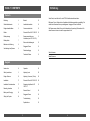
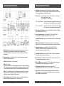
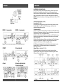
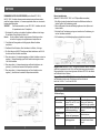
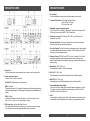
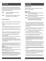
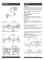
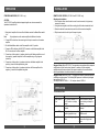
Sicherheitshinweise / Safety Instructions
Achtung !
Bitte lesen Sie alle Warnungen in dieser Anleitung. Diese
Informationen sind eingerahmt hervorgehoben und eingefügt, um Sie
über mögliche persönliche Schäden oder Beschädigungen von
Sachwerten zu informieren.
Hörschäden
Anhaltendes, übermäßiges Ausgesetztsein von Lautstärken über
85 dB kann das Hörvermögen auf Dauer beeinträchtigen. ETON
Lautsprechersysteme sind imstande, auch Lautstärken über 85 dB zu
produzieren.
Lautstärke und Fahrerbewußtsein
Der Gebrauch von Musikanlagen kann das Hören von wichtigen
Verkehrsgeräuschen behindern und dadurch während der Fahrt
Gefahren auslösen.
ETON übernimmt keine Verantwortung für Gehörschäden,
körperliche Schäden oder Sachschäden, die aus dem Gebrauch oder
Mißbrauch seiner Produkte entstehen.
ECC 300.2
ECC 500.4
ECC 600.2
ECC 600.4
ECC 1200.1
HIGH PERFORMANCE
AUDIO POWER AMPLIFIER
EINBAU /BEDIENUNG
INSTALLATION / OPERATION
Attention !
Please read all warnings found in this manual. This information is
highlighted in frames and is included to inform you of the potential danger
of personal injury or damage to property.
Hearing Damage
Continuous, excessive exposure to sound pressure levels in
excess of 85 dB can cause a loss of hearing. ETON components are
capable of producing sound pressure levels greater than 85 dB.
Volume and Driver Awareness
Use of sound components can impair your ability to hear
necessary traffic sounds and may constitute a hazard while driving your
automobile.
ETON accepts no liability for hearing loss, bodily injury or property
damage as a result of use or misuse of this product.
2
Einführung
INHALT / CONTENTS
Deutsch
Vielen Dank, dass Sie sich für eine ETON Endstufe entschieden haben.
Einleitung
4
Betrieb
10
Sicherheitshinweise
2
Lautstärke einstellen
10
Designcharakteristiken
5
Crossover einstellen
10
Subsonic-Filter für EC 1200.1 D
10
Zusammenschalten von
Verstärkern (nur EC 1200.1 D)
11
Externe Lautstärkeregler
12
Staggered Power
12
Fehlerbeseitigung
12
Technische Daten.
13
Einbau
Einbauplanung
7
Einbauplätze
7
Batterie und Aufladung
8
Verkabelung des Systems
8
Bitte lesen Sie vor Gebrauch des Verstärkers die Bedienungsanleitung sorgfältig. Sie
enthält viele Hinweise für den produkteigenen Umgang mit Ihrem Verstärker.
Die Seriennummer finden Sie an der Außenseite der Verpackung. Bitte notieren Sie
diese Nummer in dem unten dafür vorgesehenen Feld.
Serien-Nummer:
Modell-Nummer:
English
Introduction
Safety Instructions
14
2
Operation
20
Adjusting Level
20
Design Features
15
Adjusting Crossover (X-Over)
20
Installation
17
Subsonic Filter for EC 1200.1 D
20
Installation Considerations
17
Strapping Amplifiers for EC
1200.1 D
21
Mounting Locations
17
Remote Control
22
Battery and Charging
18
Staggered Power
22
Wiring the System
18
Troubleshooting
22
Specifications
23
3
4
DESIGNCHARAKTERISTIK
DESIGNCHARAKTERISTIK
E. Pegelregler: Die Pegelregler sind werkseitig auf die gängigsten Autoradios
eingestellt. Sollten Sie Ihre Endstufe nicht vollständig aussteuern können, stellen
Sie den Lautstärkepegel mit diesem Regler nach.
F
Filterschalter:
Hoch für Hochpass an z.B. Tiefmittel- Mittel- und Hochtönern
Flat für Allpass. Keine Filterung
Tief für Tiefpass an z.B. Subwoofern
HPF = High Pass Filter
Frequenzen oberhalb der eingestellten Frequenz können
können passieren, darunterliegende werden ausgefiltert.
LPF = Low Pass Filter
Frequenzen unterhalb der eingestellten Frequenz können
können passieren, darüberliegende werden ausgefiltert..
.
G. Filter-Frequenz-Einstellung: 0-500 Hz bei 12 dB/Oktav. 50-250 Hz LP TiefpassModus. Nur bei Modell ECC 1200.1.
H. Externer Lautstärkeregler: (nur bei Modell ECC 600.2 und ECC 1200.1)
Zur Regelung der Ausgangsleistung. Dämpft um bis zu 12 dB.
I.
Lautsprecheranschlüsse: Die korrekte Polarität beachten und Lautsprecherkabel
nicht erden.
J. Signal-Durchschleifung: Der Signalausgang ist parallel zum Signaleingang
geschaltet. Sie können hier ohne Aufwand einen zweiten Verstärker anschließen.
A. Hauptsicherung: Sollte diese Sicherung auslösen, müssen Sie vor erneuern der
Sicherung die Ursache feststellen. Kontaktieren Sie im Zweifelsfall Ihren
Fachhändler. Erneuern Sie die Sicherung nie durch eine Sicherung mit höherer
Amperezahl.
B. Stromanschlüsse: Zum Anschluss der Plus- und Minusspannungsversorgung
sowie für die Einschaltspannung.
GND/+12V: Minus/Masse- und Plusanschluss
REM: +12V Ausgang.
Die Endstufe stellt hier eine +12V Schaltspannung für weitere Geräte zur Verfügung
falls sie automatisch über die Radiolautsprecherausgänge einschaltet. Dies erfolgt
nur wenn das angeschlossene Radio über so genannte Brückenendstufen verfügt.
REM: +12 V Schaltplus Eingang. Die Endstufe wird vom Radio über diese Leitung
eingeschaltet falls der Signaleingang über Cinchleitungen oder über einen nicht
gebrückten High Level Eingang vom Radio erfolgt.
K. Subsonic-Filterregler: (nur bei Modell ECC 600.2 und ECC 1200.1)
Dieser Filter vermeidet, dass Signale unterhalb der Hörgrenze an Ihren
Lautsprecher gelangen und diesen zerstören.
L. Master-/Slave-Schalter: (nur bei Modell ECC 1200.1) Stellt den Verstärker bei
Zusammenschaltung auf Mater oder Slave ein.
M. SLV IN (Slave): (nur bei Modell ECC 1200.1) Bei der Parallelschaltung von zwei
Verstärkern wirkt dieser Eingang als Slave-In.
N. MAS OUT (Master): (nur bei Modell ECC 1200.1) Bei der Parallelschaltung von
zwei Verstärkern ist dies der Signalausgang zum Slave-In.
O. Filterfrequenz-Umschalter: Mit diesem Schalter können Sie die
Übernahmefrequenz zwischen 50 Hz - 500 Hz und 500 Hz - 5 kHz auswählen.
P. HI-IN: Schließen Sie hier die Lautsprecherausgänge des Radios anstelle von
Cinchleitungen (falls nicht vorhanden) an. Einschaltverhalten und Spannung an
Klemme REM wie oben beschrieben.
D. Cinch-Eingangsbuchsen: Signaleingang von den Vorverstärkerausgängen des
Radios oder anderer Signalquelle, wie z. B. DVD-Spieler usw.
5
6
EINBAU
EINBAU
Dieser Abschnitt konzentriert sich auf Erwägungen hinsichtlich des Einbaus Ihres neuen
Verstärkers im Fahrzeug. Vorausplanung Ihres Systemlayouts und der besten
Verkabelungsrouten spart Zeit beim Einbau. Prüfen Sie bei der Wahl eines Layouts für
Ihr neues System, ob alle Komponenten leicht erreichbar sind, um Einstellungen
vorzunehmen.
BATTERIE UND AUFLADUNG
VORSICHT:
VERKABELUNG DES SYSTEMS
VORSICHT:
Sollten Sie nicht sicher sein den Verstärker richtig zu installieren,
dann wenden Sie sich bitten an Ihren Fachhändler.
Vor dem Einbau des Verstärkers immer den Minuspol Ihrer
Autobatterie abklemmen. Damit vermeiden Sie Schäden am Gerät
oder Kurzschlüsse und ggf. Brandgefahr.
Gehen Sie Schritt für Schritt vor:
1. Lesen Sie die Bedienungsanleitung sorgfältig durch, bevor Sie mit dem Einbau des
Gerätes beginnen.
Verstärker belasten Batterie- und Ladesysteme zusätzlich. Prüfen Sie deshalb Batterie
und Lichtmaschine auf deren Kapazität, um Ihren Verstärker sicher betreiben zu
können. Um die Leistung Ihres Verstärkers ausnutzen zu können, empfehlen wir die
Verwendung von hochbelastbaren Batterien sowie einen zusätzlichen Kondensator.
VORSICHT:
Sollten Sie nicht sicher sein, den Verstärker richtig zu installieren,
dann wenden Sie sich bitte an Ihren Fachhändler.
VORSICHT:
Vor Einbau des Verstärkers immer den Minuspol Ihrer Autobatterie
abklemmen. Damit vermeiden Sie Schäden am Gerät oder
Kurzschlüsse und ggf. Brandgefahr.
VORSICHT:
Verlegen Sie die spannungsführenden Kabel nicht zusammen mit den
signalführenden Kabeln.
2. Klemmen Sie den Minuspol Ihrer Fahrzeugbatterie vor dem Einbau ab.
3. Verlegen Sie alle Kabel, bevor Sie Ihr Steuergerät einbauen.
4. Verlegen Sie die RCA nahe beieinander. Vermeiden Sie die Nähe zu
spannungsführenden Leitungen.
5. Verwenden Sie nur qualitativ hochwertige Kabel.
6. Beachten Sie bei der mechanischen Befestigung, dass Sie keine Benzin- oder
Bremsleitungen beschädigen. Befestigen Sie den Verstärker niemals am
Benzintank. Achten Sie auf ausreichende Belüftung.
7. Verlegen Sie die Kabel niemals außerhalb des Fahrzeugs.
8. Legen Sie die Kabel nicht über scharfe Kanten. Verwenden Sie
Durchführungshüllen aus Gummi, wenn Sie durch Metallteile verlegen müssen.
1. Planen Sie die Kabelführung sorgfältig. Die Signalkabel zusammen verlegen.
Vermeiden Sie die Nähe zu spannungsführenden Kabeln. Vermeiden Sie die Nähe
zu Elektromotoren, da diese z. T. starke Streufelder verursachen. Beim Verlegen
durch Metallteile oder die Feuerwand immer Gummischutzhüllen verwenden.
2. Das Stromkabel zum Anschluss am Verstärker am Kabelende auf ca. 13 mm
abisolieren. Das feigelegte Ende in den B+ Pol einsetzen und die
Befestigungsschraube anziehen.
Achtung: Das B+ Kabel MUSS mit einer Sicherung versehen sein. Diese sollte nicht
weiter als 45 cm vom Pluspol der Autobatterie entfernt sein. Die Sicherungshalter im
Motorraum müssen immer wasserfest sein.
3. Verwenden Sie beim Anschluss immer geeignete Kabelschuhe.
9. Schützen Sie die Batterie und das elektrische System IMMER durch
ordnungsgemäße Verwendung von Sicherungen. Installieren Sie die Sicherung
immer in der Plus-Leitung. Der Sicherungsschalter sollte dabei nicht weiter als 45
cm von der Batterie entfernt sein.
4. Isolieren Sie das Kabel für den Minuspol ca. 13 mm ab und schließen Sie dieses an
die GND-Buchse an. Das Minuskabel mit einer möglichst kurzen Verbindung an die
Karosserie klemmen. Achten Sie dabei auf einen sauberen Kontakt mit der
Fahrzeugkarosserie.
Achten Sie beim Anschluss der Minusleitung auf eine möglichst kurze Verbindung. Der
Kontakt an der Karosserie muss frei von Rost, Fett und Farbe sein.
5. Verbinden Sie den +12 V-Schaltausgang Ihres Steuergerätes mit der REM-Buchse
am Verstärker. Bei Anlegen von +12 V schaltet der Verstärker auf den
Betriebszustand „Ein“.
Einbauplätze
Die Stelle, an der Ihr verstärkter Tieftöner eingebaut ist, wirkt sich stark auf die erzielte
Soundperformance aus.
Motorraum
Das Gerät darf niemals im Motorraum installiert werden. Ein solcher Einbau führt zum
Verlust der Garantie.
Einbau im Innenraum
Achten Sie beim Einbau im Innenraum immer auf genügende Luftzirkulation. Wenn der
Verstärker unter dem Sitz moniert wird, ist auf einen Mindestabstand von 2,5 cm
rundum zu achten.
7
6. Den Verstärker gut am Fahrzeug oder Verstärkergestell befestigen. Achten Sie
darauf, dass der Verstärker nicht an Papp- oder Plastikpanelen befestigt ist.
7. Schließen Sie die RCA-Kabel an die Signal-Eingangsbuchse an.
8. Schließen Sie die Lautsprecher an die Lautsprecherklemmen an. Achten Sie auf die
richtige Polung der Lautsprecher. Achten Sie darauf, dass die Lautsprecherleitungen
keinen Massekontakt haben.
9. Vor Einschalten des Systems nochmals alle Anschlüsse auf Ihre Richtigkeit prüfen.
10. Beachten Sie auch die nachfolgenden Diagramme.
8
EINBAU
BETRIEB
LAUTSTÄRKE (LEVEL) EINSTELLEN
Drehen Sie den Levelregler auf die niedrigste Verstärkung. Drehen Sie danach die
Lautstärke ihres Steuergerätes solange hoch, bis erste Verzerrungen hörbar sind.
Drehen Sie nun den Levelregler so weit auf, bis wiederum erste leichte Verzerrungen
hörbar sind und drehen ihn dann zurück, bis keine Verzerrungen mehr hörbar sind.
HINWEIS: Detaillierte Informationen zum Einstellungsverfahren erhalten Sie vom ETON
Fachhändler.
CROSSOVER EINSTELLEN (X-OVER)
Nur bei Modell ECC 1200.1
Den Filter-Regler auf niedrigste Stellung drehen. Während das System bei normaler
Lautstärke läuft, den bzw. 55 5 kHz Filter-Regler langsam aufdrehen bis das
gewünschte Klangergebnis erreicht ist.
MONO - 1 Lautsprecher
MONO - 2 Lautsprecher
HINWEIS: Monoverstärkerlautsprecherausgänge (A und B) sind parallel angeschlossen.
2-Kanal
2-Kanal gebrückt
4-Kanal
4-Kanal als überbrückter
3-Kanal konfiguriert
9
Alle weiteren Modelle
Zur Wahl des High Pass-Modus den Schalter am Verstärker in die PH-Position bringen.
Dadurch werden Frequenzen oberhalb des Grenzpunkts durchgelassen (kann zwischen
50 und 500 Hz; bzw. 500 - 5 k Hz eingestellt werden).
Zur Wahl des All Pass-Modus den Schalter am Verstärker in die FLAT-Position bringen.
Dadurch wird eine Anpassung der Frequenzweiche verhindert und alle Frequenzen
werden durchgelassen.
Zur Wahl des Low Pass-Modus den Schalter am Verstärker in die LP-Position bringen.
Dadurch werden Frequenzen unterhalb des Grenzpunkts durchgelassen (kann
zwischen 50 und 500 Hz; bzw. 500 5k Hz eingestellt werden).
Den Filter-Regler auf niedrigste Stellung drehen. Während das System bei normaler
Lautstärke läuft, den Filter-Regler langsam aufdrehen, bis das gewünschte
Klangergebnis erreicht ist.
Subsonic-Filter (nur bei Modell EC 1200.1)
Ein Hochpassfilter, das dazu konstruiert ist zu verhindern, dass unterhalb der
Hörgrenze liegende Frequenzen vom Verstärker an die Subwoofer geleitet werden.
Während des Hörens nach Belieben einstellen.
10
BETRIEB
EINBAU
ZUSAMMENSCHALTEN VON VERSTÄRKERN (nur bei Modell ECC 1200.1)
Die ECC 1200.1 -Verstärker können paarweise aneinander angeschlossen werden,
wobei ihre Ausgänge kombiniert, d. h. zusammengeschaltet werden, um eine einzelne
Lautsprecherlast anzutreiben.
VORSICHT:
Das Zusammenschalten von zwei ECC 1200.1 -Verstärkern wird nicht
für Impedanzlasten unter 2 W empfohlen.
1. Entscheiden Sie, welcher von den beiden Verstärkern der Master ist und bringen
Sie den Master-/Slave-Schalter in Position „Out“.
Hinweis:
Nur die am Master-Verstärker vorgenommenen Einstellungen wirken
sich auf den Ausgang an den angeschlossenen Lautsprecher aus.
Externe Lautstärkeregler
(Modelle ECC 600.2 und ECC 1200.1 im LP-Tiefpass-Modus verwendbar)
1. Eine Stelle unter dem Armaturenbrett oder nahe der Mittelkonsole wählen, die
leichten Zugriff auf die Fernbedienung erlaubt.
2. Mit den beiliegenden Schrauben die Befestigungsklemme mit den Spitzen nach
hinten einbauen.
3. Das Kabel für die Fernbedienung verlegen und sowohl an der Fernbedienung, als
auch am Verstärker anschließen.
4. Die Fernbedienung in die Bestfestigungsklemme schieben bis sie einrastet
2. Cinch-Kabel des Steuergerätes an die Eingänge des Master-Verstärkers
anschließen.
3. Den Master-/Slave-Schalter am Slave-Verstärker in die Position „In“ bringen.
4. Ein Cinch-Kabel vom MAS OUT-Anschluss am Master-Verstärker an den SLV- INAnschluss am Slave-Verstärker anschließen.
5. Einen der negativen (-) Lautsprecherausgänge vom Master-Verstärker an einen der
negativen (-) Lautsprecherausgänge am Slave-Verstärker mit wenigstens einem
6 mm2 Kabel verbinden.
6. Einen der positiven (+) Lautsprecherausgänge vom Master-Verstärker an den
positiven (+) Anschluss des verwendeten Lautsprechers anschließen.
7.. Einen der positiven (+) Lautsprecherausgänge vom Slave-Verstärker an den
negativen (-) Anschluss des verwendeten Lautsprechers anschließen.
Staggered Power (Modell ECC 500.4) Zwei getrennt arbeitende Netzteile mit ebenfalls
getrennten Ausgangsstufen für die Front- und Rear-Kanäle erzeugen entsprechende
Ausgangsleistungen, dort wo sie benötigt werden. Bei Modell ECC 500.4 sind effektiv
zwei Verstärker in einem Gehäuse..
Staggered Power (Modell ECC 1200.1) Kann durch den Parallelbetrieb Master-Slave
wie beschrieben erzeugt werden. Die Leistungen erhöhen sich dadurch
bei 4W auf: 1400 W x1 bei 2W auf: 2300 W x1
BETRIEB
Fehlerbeseitigung
Symptom
Maßnahme
Diagnose
Lichtmaschine, Batterie,
Verstärker lässt sich Spannungvon B+ liegt nicht
zwischen 10,5 und 15,5 V oder Sicherung und Verkabelung
nicht einschalten
überprüfen und ggf. reparieren.
ist nicht vorhanden.
Verstärkergeräusch Verstärker hat keine ordnungs- Verkabelung überprüfen und ggf.
reparieren.
gemäße Masseverbindung.
Knallgeräusch beim Spannungsspitzen vom Steuer- Relais Einschaltmodus
gerät über die Signaleingänge zusätzlich einbauen.
Einschalten
Motorengeräusch
11
Störgeräusche über die
Signaleingangskabel.
12
Die Signalkabel im Abstand zu
spannungsführenden Kabeln
verlegen.
Modell Nr.
Ausgangsleistung (RMS)
bei 1 Ohm / Kanal
bei 2 Ohm / Kanal
bei 4 Ohm / Kanal
gebrückt
bei 2 Ohm / Kanal
bei 4 Ohm / Kanal
Maximale Stromaufnahme
Signal Rauschabstand
THD
Dämpfungsfaktor
Kanalabstand
Frequenzgang (±1.0dB)
Eingangsempfindlichkeit
Low Level Signal
High Level Signal
Schutzschaltung
Stecker Eingang
Impedanz
LED Display
Level control
HPF / LPF
Frequenzgang
Flankensteilheit
Subsonic Filter
Frequenzgang
Flankensteilheit
115Wx2+230Wx2
75Wx2+145Wx2
ECC 500.4S
210W x4
130W x4
ECC 600.4A
13
< 0.05%
> 100
101A
2300W bei 2 Verst.
1135W x1
730W x1
410W x1
ECC 1200.1D
Technische Daten können sich ohne vorherige Bekanntgabe ändern.
150mV bis 5V
1.5V bis 10V
ATO 2x30A
ATO 3x30A
ATO 2x40A
ATO 3x30A
ATO 3x30A
1 Paar RCA
2 Paar RCA
1 Paar RCA
>10 kOhm
Grüne LED Turn-on für Power und Turn-off für Protection-Anzeige
Fernbed.
Fernbed.
1 Schalter für 2 Kanäle
2 Schalter für 4 Kanäle
1 Schalter für 1 Ka
Schaltbar 50Hz bis 500Hz oder 500Hz bis 5kHz
50 bis 250Hz nur LPF
12dB / oct
1 Kontr. für 2 Ka.
1Kontr. für 1 Kanal
15Hz bis 40Hz
15Hz bis 40Hz
12dB / oct
12dB / oct
955W x1
235Wx1+440Wx1
410W x2
95A
71A
95A
> 70dB (bei 1W CEA 2006 Standard)
< 0.02%
< 0.03%
> 200
> 50dB
10Hz bis 30kHz
480W x2
280W x2
225W x2
130W x2
455W x1
52A
ECC 600.2A
ECC 300.2A
Technische Daten
Introduction
Thank you for purchasing the ETON Car Amplifier.
If, after reading your manual, you still have questions regarding this product, we
recommend that you see your ETON dealer.
The serial number can be found on the outside of the box. Please record it in the space
provided below as your permanent record. This will serve as verification of your factory
warranty and may become useful in recovering your amplifier if it is ever stolen.
Serien-Nummer:
Modell-Nummer:
14
DESIGN FEATURES
DESIGN FEATURES
E. Level Control:
This can be adjusted to match outpul levels from avariety of source units.
F. Crossover Filter Switch: HPF for High Pass Mid Tweeter
Flat for All Pass Full Range
LPF for Low Pass Subs.
G. Adjustable Crossover Frequency Control:
50 - 500 Hz or 500 Hz - 5 KHz @ 12 dB/octave for 2 and 4 channel models. 50Hz 250 Hz Low Pass only on Model ECC 1200.1 Mono Block.
H Remote Level Control: (ECC 600.2 and ECC 1200.1 only) Gain set on the
amplifier by up to 12 dB.
I.
Speaker Connections: Follow correct polarity, and do not Ground any speaker
wires. Do not connect any speaker wires together.
J. Pass Thru Outputs:The Pass-Thru provides a convenient source for daisy-chaining
an additional amplifier without running an extra set of RCA cables from the front of
the vehicle to the rear amplifier location.
K. Subsonic Control: (ECC 600.2 and ECC 1200.1 only) A variable 15 40 Hz high
pass filter designed to prevent frequencies below the audio range from being
applied to the subwoofer from the amplifier. Improving subwoofer performance and
power handling.
A. Power Fuse:
If the Fuse should blow, never replace with one of greater value than the original.
B. Power Connector terminals:
Connects Power, Ground, and Remote.
B. GND/+12V: Negative/ground- and positive pole
REM: +12 V output.
The amplifier provides a +12V voltage for further devices if it switches on automatically
via the radio speaker outputs. This only happens if the radio has so called Bridged Level
Outputs.
REM: +12V input.
Amplifier will be switched on by the radio via this cable if the signal input takes
place via chinch cables or a non bridged high level input.
L. Master/Slave: ((ECC 1200.1 only)
Set the amplifier to Master or Slave when strapping.
M. SLV IN: (ECC 1200.1 only)
When strapping, this is the slaved amplifier input from the Master amplifier.
N. MAS OUT: (ECC 1200.1 only)
When strapping, this is the Master amplifier output to the Slave amplifier.
O. Crossover Multiplier Range Switch:
This is used to set the multiplier for the crossover frequencies between x1 and x10.
The setting x1 leaves the adjustable crossover frequency from 50 Hz to 500 Hz,
while 500 Hz to 5 kHz in the setting x10.
P. HI-IN:
Connect High Level Signals from the Radio Output instead of cinch cables (in case
not available). Start-up characteristics and voltage on clamp as described above.
D. RCA Input Jacks Line Level from Radio Pre-outs:
The industry standard RCA jack provides an easy connection for signal level input.
. They are platinum to resist the signal degradation caused by corrosion.
15
16
INSTALLATION
INSTALLATION
This section focuses on some of the vehicle considerations for installing your new
amplifier. Pre-planning your system layout and best wiring routes will save installation
time. When deciding on the layout of your new system, be sure that each component
will be easily accessible for making adjustments.
CAUTION:
If you feel unsure about installing this system yourself, have it
installed by a qualified technician.
CAUTION:
Before installation, disconnect the battery negative (-) terminal to
prevent damage to the unit, fire and/or possible injury.
BATTERY AND CHARGING
To maximize the performance of your amplifier , we suggest the use of heavy duty
battery and an energy storage capacitor.
WIRING THE SYSTEM
CAUTION:
If you do not feel comfortable with wiring your new unit, please see your
local Authorized ETON Dealer for installation.
CAUTION:
Before installation, disconnect the battery negative (-) terminal to prevent
damage to the unit, fire and/or possible injury.
CAUTION:
Avoid running power wires near the low level input cables, antenna, power
leads, sensitive equipment or harnesses. The power wires carry
substantial current and could induce noise into the audio system.
Gehen Sie Schritt für Schritt vor:
1. Be sure to carefully read and understand the instructions before attempting to install
the unit.
2. For safety, disconnect the negative lead from the battery prior to beginning the
installation.
3. For easier assembly, we suggest you run all wires prior to mounting your unit in place.
4. Route all of the RAC cables close together and away from any high current wires.
5. Use high quality connectors for a reliable installation and to minimize signal or power
loss.
1. Plan the wire routing. Keep RCA cables close together but isolated from the amplifier's power cables and
any high power accessories, especially electric motors. This is done to prevent the noise from radiated
electrical fields into the audio signal. When feeding the wires through the firewall or any metal barrier, protect
them with plastic or rubber grommets to prevent short circuits. Leave the wires long at this point to adjust for
a precise fit at a later time.
2. Prepare the power cable for attachment to the amplifier by stripping ½” of insulation from the end of the wire.
Insert the bared wire int o the B+ terminal and tighten the set screw to secure the cable in place.
Note:
The B+ cable MUST be fused 18” or less from the battery. Install the fuse holder under the hood
and prepare the cable ends as stated above. Connections should be water tight.
6. Think before you drill! Be careful not to cut or drill into gas tanks, fuel lines, brake or
hydraulic lines, vacuum lines or electrical wiring when working on any vehicle.
3. Trim the power cable within 18” of the battery and strip ½” of insulation from the end of the wire.
7. Never run wires underneath the vehicle. Running the wires inside the vehicle
provides the best protection.
4. Strip ½” from the battery end of the power cable and crimp a large ring terminal to the cable. Use the ring
terminal to connect the battery positive terminal. DO NOT install the fuse at this time.
8. Avoid running wires over or through sharp edges. Use rubber or plastic grommets to
protect any wires routed through metal, especially the firewall.
5. Perpare the grounding cable for attachment to the amplifier by stripping ½” of insulation from the end of the
wire. Insert the bared wire into the GND terminal and tighten the set screw to secure the cable in place.
Prepare the chassis ground by scraping any paint from the metal surface and thoroughly clean the area.
Strip the other end of the wire and attach a ring connector. Fasten the cable to the chassis using a nonanodized screw and a star washer.
9. ALWAYS protect the battery and electrical system from damage with proper fusing.
Install the appropriate fuse holder and fuse on the + 12 V power wire within 18 “ (45.7
cm) of the battery terminal.
When grounding to the chassis of the vehicle, scrape all paint from the metal to ensure
a good, clean ground connection. Grounding connections should be as short as
possible and always be connected to metal that is welded to the main body, or chassis,
of the vehicle.
MOUNTING LOCATIONS The mounting position of your amplifier will have a great
effect on the sound and performance produced.
Engine Compartment Never mount this unit in the engine compartment. Mounting the
unit in the engine compartment will void your warranty.
Passenger Compartment Mounting Mounting the amplifier in the passenger
compartment will work as long as you provide a sufficient amount of air for the amplifier
to cool itself. If you are going to mount the amplifier under the seat of the vehicle, you
must have at least 1” (2.54 cm) of air gap around the amplifier's heatsink.
17
6. Prepare the REM turn-on wire for connection to the amplifier by stripping ½” of insulation from the wire end.
Insert the bared wire into the REM terminal an tighten the set screw to secure the cable into place. Connect
the other enf of the REM wire to a switched 12 volt positive source. The switched voltage is usually taken
from the source unit's accessory lead. If the source unit does not have this output available, the
recommended solution is to wire a mechanical switch in line with a 12 volt source to activate the amplifier.
7. Securely mount the amplifier to the vehicle or amp rack. Be careful not to mount the amplifier on cardboard
or plastic panels. Doing so may enable the screws to pull out from the panel due to road vibration or sudden
vehicle stops.
8. Connect the source signal to the amplifier by plugging the RCA cables/high level inputs into the input jacks at
the amplifier. Connect the speakers. Strip the speaker wires ½” and insert into the speaker terminal and
tighten the set screw to secure into place. Be sure to maintain proper speaker polarity. DO NOT chassis
ground any of the speaker leads as unstable operation may result.
9. Perform a final check of the completed system wiring to ensure that all connections are accurate. Check all
power and ground connections for frayed wires and loose connections which could cause problems.
18
INSTALLATION
OPERATION
ADJUSTING LEVEL
To adjust the level setting, turn the amplifier levels all the way down. Turn the source
unit volume up until distortion is audible and then turn it down a bit until the distortion is
inaudible. This will be about two thirds of all the way up on most source units. Next, turn
the amplifier level setting until once again distortion is audible and then back it down
until the distortion is inaudible.
NOTE: For a more in depth setting procedure, contact ETON Technical Support.
ADJUSTING CROSSOVER (X-OVER)
Model ECC 1200.1 only
Turn the crossover adjustment knob all the way down. With the system playing at
normal listening level, turn the crossover adjustment knob up slowly until the desired
crossover point is achieved.
All Other Models
Placing the switch in the HPF position sets the amplifier to the high pass mode,
enabling frequencies above the cut-off point to pass, adjustable between 50 - 500 Hz or
500 Hz - 5 kHz.
Placing the switch in the Flat position sets the amplifier to the all pass mode, preventing
any crossover adjustment, allowing all frequencies to pass.
Placing the switch in the LPF position sets the amplifier to the low pass mode, enabling
frequencies below the cut-off point to pass, adjustable between 50 - 500 Hz or 500 Hz 5 kHz.
NOTE: Mono amplifier speaker outputs (A & B) are wired in parallel internally..
Turn the crossover adjustment knob all the way down. With the system playing, turn the
crossover adjustment knob up slowly until the desired crossover point is achieved.
SUBSONIC (ECC 600.2 and ECC 1200.1 only)
A variable 15 - 40 Hz high pass filter designed to prevent frequencies below the audio
range from being applied to the subwoofer from the amplifier.
Set this to your personal preference while listening to the system.
19
20
OPERATION
INSTALLATION
STRAPPING AMPLIFIERS (ECC 1200.1 only)
CAUTION:
Two ECC 1200.1 amplifiers that are strapped together are not recommended for
impedance loads below 2W.
REMOTE LEVEL CONTROL (ECC 600.2 and ECC 1200.1 only)
Mounting and installation
1. Find a location, either under the dash or near the center console, that gives easy
access to the remote.
2. Using the screw supplied, install the mounting clip with the tabs towards the back.
3. Route the cable for the remote and connect to both, the remote and amplifier.
1. Select which amplifier of the two will be the Master and set the Master/Slave switch
“out”.
Note:
4. Slip the remote onto the unit clip until it snaps into place.
Only adjustments on the master amplifier will effective in functions.
2. Connect RCA cables from the source signal to the input connection on the master
amplifier.
3. Set the Master/Slave switch on the Slave amplifier to the “in” position.
4. Connect a RCA cable from the MAS OUT connector on the Master amplifier to the
SLV IN connector on the Slave amplifier.
5. Connect one of the negative (-) speaker outputs from the Master amplifier to one of
the negative (-) speaker outputs on the Slave amplifier using a 10 gauge wire
(minimum).
6. Connect one of the positive (+) speaker outputs from the Master amplifier to the
positive (+) terminal of the speaker being used.
7.. Connect one of the positive (+) speaker outputs from the Slave amplifier to the
negative (-) terminal of the speaker being used.
Staggered Power (Model ECC 500.4): Two separate power supplies with two separate
output sections for the front and rear channels. In essence, it is two completely
amplifiers sharing the same chassis. More power is created on the rear channels to
allow the performance to be delivered where it is needed most.
Staggered Power (Model ECC1200.1): The Mono Block handling subwoofer speakers
sometimes need more power. The following RMS power can be achieved by strapped
two amplifiers @ 14.4 V:
4W Load per channel: 1400W x1 2W Load per channel: 2300W x1
OPERATION
TROUBLESHOOTING
21
Symptom
Diagnosis
Remedy
Amplifier does not
turn on
B+ or REM not between 10.5
and 15.5 volts or no voltage
present.
Check the alternator, battery,
fuse, and wiring and reapir as
necessary
Amplifier Noise
Amplifier is not properly
grounded
Check wiring and repair as
necessary.
(Turn-on POP)
Voltage spike from source unit Connect a relay turn-on module
to REM terminal
is entering amplifier's input
Engine Noise
Noise is radiating into signal
cables.
22
Re-route signal cables away
from sources of high power
cables.
Modell No.
RMS power
@ 1 Ohm / channel
@ 2 Ohms / channel
@ 4 Ohms / channel
Bridged RMS power
@ 2 Ohms / channel
@ 4 Ohms / channel
Maximum current
Signal to noise ratio
THD
Damping faktor
Channel Separation
Freq. response (±1.0dB)
Input sensivity
Low Level Signal
High Level Signal
Fuses
Input Connector
Impedance
LED Display
Remote control
HPF / LPF
Frequenzgang
Slope
variable Subsonic Controls
Frequency Range
Slope
115Wx2+230Wx2
75Wx2+145Wx2
ECC 500.4S
210W x4
130W x4
ECC 600.4A
23
1Contr. for 1 channel
15Hz to 40Hz
12dB / oct
Level Control
1 switch for 1 ch
50 to 250Hz LPF only
ATO 3x30A
1 pair of RCA
< 0.05%
> 100
101A
2300W with 2 Sets.
1135W x1
730W x1
410W x1
ECC 1200.1D
Specifications subject to change without notice.
150mV to 5V
1.5V to 10V
ATO 2x30A
ATO 3x30A
ATO 2x40A
ATO 3x30A
1 pair of RCA
2 pair of RCA
>10 kOhm
Green LED Turn-on for Power and Turn-off for Protection display
Level Control.
1 switch for 2 channels
2 switch for 4 channels
Switchable 50Hz to 500Hz or 500Hz to 5kHz
12dB / oct
1 Contr. for 2 ch.
15Hz to 40Hz
12dB / oct
955W x1
235Wx1+440Wx1 410W x2
95A
71A
95A
> 70dB (@1W CEA 2006 Standard)
< 0.02%
< 0.03%
> 200
> 50dB
10Hz to 30kHz
480W x2
280W x2
225W x2
130W x2
455W x1
52A
ECC 600.2A
ECC 300.2A
SPECIFICATIONS
ETON behält sich das Recht vor, die beschriebenen Produkte ohne
jegliche Vorankündigung zu verändern oder zu verbessern. Alle
Rechte sind vorbehalten. Die auch teilweise Vervielfältigung des
vorliegenden Handbuchs ist untersagt.
ETON reserves the rigth to make modifications or improvements to
the products illustrated without notice thereof. All rights belong to
the respective owners. Total or partial reproduction of this User's
Guide is prohibited.