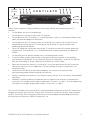
1
ARRIS
DVR Receiver
Installation Manual
VIP2250
For use with your AT&T U-verse TV Service
CAUTION
RISK OF ELECTRIC SHOCK
DO NOT OPEN
TO REDUCE RISK OF ELECTRIC SHOCK, DO NOT
REMOVE COVER (OR BACK). NO USER-SERVICEABLE
PARTS INSIDE. REFER SERVICING TO QUALIFIED
SERVICE PERSONNEL.
CAUTION
RISK OF ELECTRIC SHOCK
DO NOT OPEN
TO REDUCE RISK OF ELECTRIC SHOCK, DO NOT
Graphical
symbols and supplemental warning markings are located on the back and bottom
REMOVE COVER (OR BACK). NO USER-SERVICEABLE
of the
terminal.
PARTS
INSIDE. REFER SERVICING TO QUALIFIED
SERVICE PERSONNEL.
WARNING
TO REDUCE THE RISK OF FIRE OR SHOCK, DO NOT EXPOSE THIS APPLIANCE TO RAIN
OR MOISTURE.
The lightning flash with arrowhead symbol within an equilateral triangle
is intended to alert the user to the presence of uninsulated dangerous
voltage within the product’s enclosure that may be of sufficient
magnitude to constitute a risk of electric shock to persons.
The exclamation point within an equilateral triangle is intended to alert
the user to the presence of important operating and maintenance
(servicing) instructions in the literature accompanying the appliance.
Product identification and supply rating are provided on the label found
on the bottom of the unit.
IMPORTANT SAFETY INSTRUCTIONS
•
Read these instructions.
•
Keep these instructions.
•
Heed all warnings.
•
Follow all instructions.
•
Do not use this apparatus near water.
•
Clean only with a dry cloth.
•
Do not block any ventilation openings. Install according to the manufacturer’s
instructions.
•
Do not install near any heat sources, such as radiators, heat registers, stoves, or other
apparatus (including amplifiers) that produce heat.
•
Protect the power cord from being walked on or pinched, particularly at plugs,
convenience receptacles, and the point where they exit from the apparatus.
•
Only use attachments/accessories specified by the manufacturer.
•
Unplug this apparatus during lightning storms or when unused for long periods of
time.
•
Refer all servicing to qualified service personnel. Servicing is required when the
apparatus has been damaged in any way, such as the power supply cord or plug
is damaged, liquid has been spilled or objects have fallen into the apparatus, the
apparatus has been exposed to rain or moisture, does not operate normally, or has
been dropped.
ii
VIP2250 U-verse DVR Receiver Installation Manual
At least
2 inches
V E N T I L AT E
2 inches
2 inches
Follow these important safety guidelines when positioning and connecting your TV
receiver:
• Do not block the slots and openings
•
Do not place anything on top of the TV receiver
•
Do not position the TV receiver in a confined space, such as an enclosed cabinet, that
does not provide adequate ventilation.
•
Do not position the TV receiver near any external heat source that could raise the
temperature around the unit. Do not place the terminal on top of another heat
producing electronic device.
•
Allow for adequate ventilation around the TV receiver to maintain normal operating
temperature. Do not place it in a sealed enclosure without providing for adequate
airflow.
•
Do not plug the AC power adapter into a switched power outlet.
•
A coaxial cable screen shield needs to be connected to the earth at the building
entrance per ANSI/NFPA 70, the National Electrical Code (NEC), in particular Section
820.93, Grounding of Outer Conductive Shield of a Coaxial Cable.
•
Because the receiver contains a hard drive, it must be positioned so that it remains
horizontal and rests on its rubber feet. Do not attempt to mount or position it in a
vertical position.
•
To allow the disk drive to spin down properly, wait at least 10 seconds after
disconnecting power before moving the receiver.
•
Always transport the receiver in its original factory carton, or in an equally well-padded
container.
•
Whether installed or being transported, do not expose the receiver to temperature
extremes. The temperature range for operation is from 0° to +40°C. The non-operating
(transport or storage) temperature range is from -40° to +60°C.
This manual includes the manufacturer’s recommended safeguards and all the information
needed to connect your receiver to both your in-home IP network and your entertainment
system. The safety and installation information was developed and provided primarily by
the receiver manufacturer, ARRIS Enterprises, Inc.
VIP2250 U-verse DVR Receiver Installation Manual
iii
Contents
Introduction . . . . . . . . . . . . . . . . . . . . . . . . . . . . . . . . . . . . . . . . . . . . . . 1
Overview . . . . . . . . . . . . . . . . . . . . . . . . . . . . . . . . . . . . . . . . . . . . . . . . 2
Front Panel . . . . . . . . . . . . . . . . . . . . . . . . . . . . . . . . . . . . . . . . . . . . . . . 2
Rear Panel . . . . . . . . . . . . . . . . . . . . . . . . . . . . . . . . . . . . . . . . . . . . . . . 3
Connecting Your TV Receiver . . . . . . . . . . . . . . . . . . . . . . . . . . . . . . . . . 4
Connection Options . . . . . . . . . . . . . . . . . . . . . . . . . . . . . . . . . . . . . . . . 4
Connecting Your TV Receiver . . . . . . . . . . . . . . . . . . . . . . . . . . . . . . . . . 5
Common Cabling Examples . . . . . . . . . . . . . . . . . . . . . . . . . . . . . . . . . 5
Connecting to an HDTV – Video Only . . . . . . . . . . . . . . . . . . . . . . . . . . 6
Connecting to an HDTV – Audio Only . . . . . . . . . . . . . . . . . . . . . . . . . . 7
Connecting to a Home Theater Receiver . . . . . . . . . . . . . . . . . . . . . . . . 8
Connecting to a Stereo TV . . . . . . . . . . . . . . . . . . . . . . . . . . . . . . . . . . . 9
Connecting to a Stereo TV and Stereo VCR . . . . . . . . . . . . . . . . . . . . . . 10
Connecting to a Home Theater Receiver, TV, and VCR . . . . . . . . . . . . . . 11
Troubleshooting . . . . . . . . . . . . . . . . . . . . . . . . . . . . . . . . . . . . . . . . . . 12
iv
VIP2250 U-verse DVR Receiver Installation Manual
Introduction
Congratulations on receiving this ARRIS VIP2250 U-verse DVR TV Receiver.
The VIP2250 provides these extraordinary home entertainment features:
•
High Definition TV (HDTV), which provides up to twice the color resolution and up to
six times the sharpness of standard TV when connected to an HD-capable TV
•
A digital video recorder (DVR), which can record Standard Definition and High
Definition programs
•
A direct digital connection to consumer audio and video devices through multiple
interfaces
•
Video on Demand (VoD)
•
Commercial free, CD quality music
This installation manual introduces the basic features, outlines important safeguards, and
provides options for integrating your TV receiver into your entertainment system. Take a
few moments to read through this manual. Its configuration diagrams and troubleshooting
section will help you make the most of your home entertainment experience.
Included in the carton:
•
VIP2250 Digital Video Recorder (DVR) Receiver
•
Power adapter
For more information about your U-verse TV service, refer to the other documentation from
your service provider.
Dimensions: 10.0” W. x 8.0” D., x 2.2” H.
Unit Weight: 4.37 lbs.
Top Assembly Weight (incl. carton and all inserts): VIP2250 U-verse DVR Receiver Installation Manual
6.39 lbs.
1
Overview
Front Panel
The illustration below and the table following it describe the VIP2250 front-panel features.
1
2
Key
Item
1
POWER
3
4 5
6
7
Function
Turns the U-verse TV receiver on or off
If held for ten (10) seconds or longer, restarts the TV receiver
Lights green when the TV receiver is on
2
2
USB
USB 2.0 connector
3
LINK
Lights green when receiving a video stream
4
HD
5
RECORD
6
MENU
7
Up/Down
arrow keys
Changes the channel (channel up/channel down)
Left/Right
arrow keys
Use to navigate through on-screen program guide and menu
OK
center key
Use to select programs or menu options
Lights blue when receiving video resolution of 720p or 1080i
Lights red when a recording is in progress
Displays the menu
VIP2250 U-verse DVR Receiver Installation Manual
Overview
Rear Panel
The illustration below and the table following it describe the VIP2250 front-panel features.
1
2
3
4
5
7
8
9
10
11
12
6
Key
Item
Function
1
TO WALL
(VIDEO IN)
Coaxial input for digital signal from your service provider
2
NETWORK
Ethernet 10/100Base-T RJ-45 port for IP video output
3
eSATA
4
OPTICAL
(Reserved for future use)
AT&T VIP2232 Rear Panel (573205-007-00)
Toslink (S/PDIF) audio output to a digital home theater
receiver
5
S-VIDEO
6
Y Pb Pr
7
VIDEO OUT
RCA video outputs to a TV, VCR, or other device
8
AUDIO OUT
R and L
Left and right RCA stereo audio outputs
9
TO TV
(VIDEO OUT)
Coaxial output to connect the TV receiver to the TV or VCR
10
HDMI
Connects to a High Definition TV or home theater receiver
with an HDMI input (for a DVI input, use an HDMI-to-DVI
adapter)
11
USB
12
POWER
+12 VDC
High-quality video output to a VCR or TV that accepts
S-Video. It carries video only; you must also connect to the
TV or home theater receiver for audio
RCA component video outputs to an HDTV
USB 2.0 connector
Connector for the DC power adapter (36 W.)
VIP2250 U-verse DVR Receiver Installation Manual
3
Connecting Your TV Receiver
This section describes connecting the VIP2250 to your home entertainment system.
Instructions and diagrams are included for connections to:
•
High-Definition TV (HDTV)
•
Home Theater Receiver–Audio
•
Stereo TV
•
Stereo TV and Stereo VCR
•
Home Theater Receiver, TV, and VCR
Before you move or change components on your entertainment system, disconnect power
from the TV receiver.
Connection Options
The VIP2250 offers the following video outputs:
HDTV
HDMI or Component video
Standard
S-Video, Composite video, or RF coaxial
To determine the available inputs on your TV, check the manual supplied with the TV or
on the TV itself. Use the following guidelines to determine the best connections for your
system. Use one of the following.
Connector
HDMI
HDMI
Description
HDMI offers higher video quality than component video. If your
HDTV has an HDMI input, use the HDMI connector.
HDMI provides both digital video and digital audio (including
Dolby® Digital 5.1 Surround Sound). No other connections are
necessary.
High-Definition
If your HDTV has a DVI input, you can use an HDMI-to-DVI
converter cable to connect to the VIP2250 HDMI connector.
Use a cable with an HDMI connector on one end and a DVI
connector on the other end. We do not recommend using an
HDMI-to-DVI or DVI-to-HDMI adapter. Because DVI does not
carry audio, a separate audio connection is required for a DVI
TV. If your TV has an optical S/PDIF audio connection, use the
OPTICAL connection. Otherwise, use the baseband AUDIO L
and R connections.
Component
Video
The Y Pb Pr connectors provide component video, the most
widely supported HDTV connection.
Component video provides a High-Definition analog video signal.
If your equipment supports an optical S/PDIF audio connection,
use the OPTICAL connection. Otherwise, use the baseband
AUDIO L and R connections.
4
VIP2250 U-verse DVR Receiver Installation Manual
Connecting Your TV Receiver
Connector
S-Video
Standard-Definition
S VIDEO
Composite
Video
VIDEO
OUT
RF Coaxial
Description
If your standard TV has an S-Video input, use S VIDEO, which
is the highest quality Standard-Definition video output on the
VIP2250.
S-Video provides a Standard-Definition analog video signal. If
your equipment supports an optical S/PDIF audio connection,
use the OPTICAL connection. Otherwise, use the baseband
AUDIO L and R connections.
If your standard TV does not have an S-Video input, use the
composite VIDEO OUT connector.
Composite video provides a Standard-Definition analog video
signal. If your equipment supports an optical S/PDIF audio
connection, use the OPTICAL connection. Otherwise, use the
baseband AUDIO L and R connections.
If your TV only has a coaxial RF input, use the coaxial TO
TV (VIDEO OUT) connector. RF coaxial provides a StandardDefinition video and audio signal. No other connections are
necessary.
Common Cabling Examples
The following cabling diagrams illustrate common sample audio/video (A/V) connections.
When connecting other components to your TV Receiver, refer to the other component
installation manuals for additional connection information.
VIP2250 U-verse DVR Receiver Installation Manual
5
Connecting to an HDTV – Video Only
HDMI
RF (75 Ohm) Component video
connection
connection
connection
VIP2200
L
Y
R
eSATA
TO WALL
(VIDEO IN)
NETWORK
OPTICAL
Pb
TO TV
(VIDEO OUT)
POWER
HDMI
USB
Pr
VIDEO OUT
+12V
DC
AUDIO OUT
Video in
Either / or
Sample HDTV
Component
Video Input
HDMI
Y
Pb
Pr
CABLE/
ANTENNA IN
•
Connect an RF coaxial cable to the cable wall outlet and the TO WALL (VIDEO IN)
connector on the TV receiver.
•
If your HDTV has an HDMI input, connect an HDMI cable to the HDMI connector.
HDMI connection carries both video and audio signals.
•
If your HDTV has a DVI input, you can use an HDMI to DVI converter to connect to the
VIP2250 HDMI connector.
•
If your HDTV has component video, connect component video cables to the Y, Pb, and
Pr connectors.
DVI and component video carry video signals only. To connect the audio, refer to the
following page. To connect to a home theater receiver, refer to “Connecting to a Home
Theater Receiver – Audio Only.”
6
VIP2250 U-verse DVR Receiver Installation Manual
Connecting to an HDTV – Audio Only
RF (75 Ohm) Optical S/PDIF Baseband audio
connection
connection
connection
VIP2200
L
Y
R
eSATA
TO WALL
(VIDEO IN)
NETWORK
OPTICAL
Pb
TO TV
(VIDEO OUT)
POWER
HDMI
USB
Pr
VIDEO OUT
S VIDEO
+12V
DC
AUDIO OUT
Video in
Either / or
INPUT
S-VIDEO
VIDEO
CABLE/
ANTENNA IN
OPTICAL
SPDIF
AUDIO LEFT
AUDIO RIGHT
Sample HDTV audio inputs
If your equipment supports it, use the OPTICAL S/PDIF output. Otherwise, use the AUDIO
OUT L and R connectors. In most cases, S/PDIF offers better audio quality, including
support for Dolby Digital 5.1 Surround Sound.
HDMI carries video and audio. If you connect your HDTV using HDMI, no additional audio
connections to the TV are necessary.
VIP2250 U-verse DVR Receiver Installation Manual
7
Connecting to a Home Theater Receiver
RF (75 Ohm) Optical S/PDIF Baseband audio
connection
connection
connection
VIP2200
L
Y
R
eSATA
TO WALL
(VIDEO IN)
NETWORK
OPTICAL
Pb
TO TV
(VIDEO OUT)
POWER
HDMI
Pr
VIDEO OUT
S VIDEO
USB
+12V
DC
AUDIO OUT
Video in
Either / or
AUDIO
R
L
VIDEO
VIDEO
S-VIDEO
DIGITAL INPUT
COAX
DVD
CABLE/TV
OPTICAL
VIDEO 2
TV/MONITOR
OUTPUT
SPEAKER
CONNECTORS
IN
VCR
VIDEO S-VIDEO
OUT
Sample home theater receiver
If your home theater receiver supports it, use the OPTICAL S/PDIF output. Otherwise,
use the AUDIO OUT L and R connectors. In most cases, S/PDIF offers better audio quality,
including support for Dolby Digital 5.1 Surround Sound.
Need Help:
Contact AT&T ConnecTech® service to learn about affordable flat-rate home theater
installation services.
Call (800) 344-1734 to speak with an AT&T ConnecTech Representative.
(Not available in all areas; See offers and terms & conditions at www.att.com/ConnecTech)
8
VIP2250 U-verse DVR Receiver Installation Manual
Connecting to a Stereo TV
RF (75 Ohm)
connection
S-Video Baseband video Baseband audio Optical S/PDIF
connection
connection
connection
connection
VIP2200
L
Y
R
eSATA
TO WALL
(VIDEO IN)
NETWORK
OPTICAL
Pb
TO TV
(VIDEO OUT)
Pr
S VIDEO
VIDEO OUT
POWER
HDMI
USB
+12V
DC
AUDIO OUT
Video in
Either / or
Sample stereoTV
INPUT
S-VIDEO
VIDEO
CABLE/
ANTENNA IN
AUDIO LEFT
AUDIO RIGHT
This video connection method does not support HD video. For more information, see
“Connecting an HDTV – Video Only.”
VIP2250 U-verse DVR Receiver Installation Manual
9
Connecting to a Stereo TV and Stereo VCR
RF (75 Ohm) Baseband video Baseband audio
connection
connection
connection
VIP2200
L
Y
R
eSATA
TO WALL
(VIDEO IN)
NETWORK
OPTICAL
Pb
TO TV
(VIDEO OUT)
Pr
VIDEO OUT
S VIDEO
POWER
HDMI
USB
+12V
DC
AUDIO OUT
Video in
Sample stereoTV
Sample stereo VCR
INPUT
INPUT
CABLE/
ANTENNA IN
AUDIO
VIDEO
AUDIO
VIDEO
ToTV
L
R
S-VIDEO
OUTPUT
L
R
VIDEO
CABLE/
ANTENNA IN
AUDIO LEFT
AUDIO RIGHT
This video connection method does not support HD video. For more information, see
“Connecting to an HDTV – Video Only.”
10
VIP2250 U-verse DVR Receiver Installation Manual
Connecting to a Home Theater Receiver, TV, and VCR
RF (75 Ohm) Baseband video Baseband audio Optical S/PDIF
connection
connection
connection
connection
VIP2200
L
Y
R
eSATA
TO WALL
(VIDEO IN)
NETWORK
OPTICAL
TO TV
(VIDEO OUT)
Pb
POWER
HDMI
Pr
VIDEO OUT
S VIDEO
USB
+12V
DC
AUDIO OUT
Video in
Sample stereo VCR
Sample stereoTV
INPUT
INPUT
CABLE/
ANTENNA IN
AUDIO
S-VIDEO
OUTPUT
VIDEO
AUDIO
VIDEO
VIDEO
R
L
R
AUDIO LEFT
CABLE/
ANTENNA IN
ToTV
L
AUDIO RIGHT
Sample home
theater receiver
AUDIO
R
L
VIDEO
VIDEO
S-VIDEO
DVD
OPTICAL
CABLE/TV
VIDEO 2
TV/MONITOR
OUTPUT
SPEAKER
CONNECTORS
IN
VIDEO S-VIDEO
VCR
OUT
This video connection method does not support HD video. For more information, see
“Connecting to an HDTV – Video Only.”
VIP2250 U-verse DVR Receiver Installation Manual
11
Troubleshooting
Before calling your service provider, review this troubleshooting guide. If the suggestions
do not help you quickly solve a problem, contact your service provider.
Problem
Possible Solution
The TV receiver will
not power on.
Verify that the power adapter is connected to the TV receiver
and an AC outlet. Unplug the TV receiver from the outlet, plug
it back in, and press the POWER button.
If the TV receiver is connected to a switched outlet on a wall
or another unit, verify that the switch or unit is powered on.
Unplug the TV receiver from the AC outlet, plug it back in, and
press the POWER button.
Press the POWER button on the TV receiver front panel instead
of the remote control. The batteries in the remote control may
be depleted.
The remote control
does not work.
Verify that the TV is on.
Verify that the remote control is on AT&T mode.
Verify that there are no obstructions between the remote
control and the TV receiver. Aim the remote control directly at
the TV receiver front panel, not the TV or VCR.
The angle between the remote control and the TV receiver may
be too large. Stand in front of the TV receiver and not too far to
either side.
Press and release operation keys one at a time, firmly and
deliberately.
Try changing channels using the buttons on the TV receiver
front panel.
Check the batteries in the remote control. Install new batteries
if needed.
12
VIP2250 U-verse DVR Receiver Installation Manual
Troubleshooting
Problem
Possible Solution
There is no audio
when viewing TV
channels.
Verify that the Mute button on the remote control has not been
pressed. Press Mute on the remote control to restore sound.
If the TV receiver audio output is connected to the TV, verify
that the Mute button on the TV has not been pressed.
If the TV receiver audio output is connected to a home theater
receiver, verify that the home theater receiver is set to the
appropriate input source and its Mute button has not been
pressed.
Verify that you have the correct cables for the audio ports.
Verify that the audio cables are firmly connected between the
TV receiver and the audio playback device (TV, home theater
receiver, etc.).
There is no audio
from the center and/
or surround speakers
of a home theater
receiver connected to
the TV receiver.
Not all Dolby Digital programs feature full 5.1 surround sound.
In some cases, the programs may only contain left and right
stereo audio.
Verify that the Optical S/PDIF cable is firmly connected to the
TV receiver and the home theater receiver.
Verify that the home theater receiver is set to a surround
sound audio mode (Dolby Digital, Dolby Pro Logic® II, Dolby
Pro Logic).
Verify that the home theater receiver is properly configured to
work with all connected speakers.
VIP2250 U-verse DVR Receiver Installation Manual
13
Regulatory Information
Federal Communications Commission Radio and Television
Interference Statement for a Class ‘B’ Device
This equipment has been tested and found to comply with the limits for a Class B digital device,
pursuant to part 15 of the FCC Rules. These limits are designed to provide reasonable protection
against harmful interference in the residential installation. This equipment generates, uses, and can
radiate radio frequency energy and, if not installed and used in accordance with the instructions,
may cause harmful interference to radio communications. However, there is no guarantee that
interference will not occur in a particular installation.
If the equipment does cause harmful interference to radio or television reception, which can
be determined by turning the equipment off and on, the user is encouraged to try to correct the
interference by one of the following measures:
•
•
•
•
Reorient or relocate the device and/or the antenna receiving the interference.
Increase the separation between the equipment and the affected receiver
Connect the equipment on a circuit different from the one the receiver is on
Contact your service provider for help.
Changes or modification not expressly approved by the party responsible for compliance could void
the user’s authority to operate the equipment.
Declaration of Conformity
According to 47 CFR, Parts 2 and 15 for Class B Personal Computers and Peripherals;
and/or CPU Boards and Power Supplies used with Class B Personal Computers, ARRIS
Enterprises, Inc., 6450 Sequence Drive, San Diego, CA 92121, 1 800 225 9446, declares
under sole responsibility that the product identifies with 47 CFR Part 2 and 15 of the FCC
Rules as a Class B digital device. Each product marketed is identical to the representative
unit tested and found to be compliant with the standards. Records maintained continue to
reflect the equipment being produced can be expected to be within the variation accepted,
due to quantity production and testing on a statistical basis as required by 47 CFR 2.909.
Operation is subject to the following condition: This device must accept any interference
received, including interference that may cause undesired operation. The above named
party is responsible for ensuring that the equipment complies with the standards of 47
CFR, Paragraphs 15.101 to 15.109. The Class B digital apparatus meets all requirements of
the Canadian Interface Causing Equipment Regulations.
14
VIP2250 U-verse DVR Receiver Installation Manual
Software License
VIP2250 U-verse DVR Receiver
ARRIS Enterprises, Inc. (“ARRIS”)
3871 Lakefield Drive
Suwanee, Georgia 30024 USA
IMPORTANT: PLEASE READ THIS SOFTWARE LICENSE (“LICENSE”) CAREFULLY BEFORE YOU USE ANY
SOFTWARE, FIRMWARE, AND RELATED DOCUMENTATION (“SOFTWARE”) PROVIDED WITH ANY ARRIS
IP VIDEO RECEIVER OR HOME THEATER SYSTEM (EACH SHALL BE REFERRED TO IN THIS LICENSE AS A
“RECEIVER”). BY USING THE RECEIVER AND/OR USING ANY OF THE SOFTWARE, YOU INDICATE YOUR
ACCEPTANCE OF EACH OF THE TERMS OF THIS LICENSE. UPON ACCEPTANCE, THIS LICENSE WILL BE A
LEGALLY BINDING AGREEMENT BETWEEN YOU AND ARRIS. THE TERMS OF THIS LICENSE APPLY TO YOU
AND TO ANY SUBSEQUENT USER OF THIS SOFTWARE.
IF YOU DO NOT AGREE TO ALL OF THE TERMS OF THIS LICENSE (I) DO NOT USE THE SOFTWARE
AND (II) RETURN THE RECEIVER AND THE SOFTWARE (COLLECTIVELY, “PRODUCT”), INCLUDING ALL
COMPONENTS, DOCUMENTATION, AND ANY OTHER MATERIALS PROVIDED WITH THE PRODUCT,
TO YOUR POINT OF PURCHASE OR SERVICE PROVIDER, AS THE CASE MAY BE, FOR A FULL REFUND.
The Software includes associated media, any printed materials, and any “on line” or electronic
documentation. Software provided by third parties may be subject to separate end user license
agreements from the manufacturers of such Software. The Software is never sold. ARRIS licenses
the Software to the original customer and to any subsequent licensee for personal use only on the
terms of this License. ARRIS and its third party licensors retain the ownership of the Software.
You may:
USE the Software only in connection with the operation of the Product.
TRANSFER the Software (including all component parts and printed materials) permanently to
another person, but only if the person agrees to accept all of the terms of this License. If you transfer
the Software, you must at the same time transfer the Product and all copies of the Software (if
applicable) to the same person or destroy any copies not transferred.
TERMINATE this License by destroying the original and all copies of the Software (if applicable) in
whatever form.
You may not:
(1) Loan, distribute, rent, lease, give, sublicense, or otherwise transfer the Software, in whole or in
part, to any other person, except as permitted under the TRANSFER paragraph above. (2) Copy or
translate the User Guide included with the Software, other than for personal use. (3) Copy, alter,
translate, decompile, disassemble, or reverse engineer the Software, including but not limited to
modifying the Software to make it operate on non compatible hardware. (4) Remove, alter, or cause
not to be displayed any copyright notices or startup message contained in the Software programs or
documentation. (5) Export the Software or the Product components in violation of any United States
export laws.
The Product is not designed or intended for use in on line control of aircraft, air traffic, aircraft
navigation, or aircraft communications; or in design, construction, operation, or maintenance of any
nuclear facility. ARRIS AND ITS THIRD PARTY LICENSORS DISCLAIM ANY EXPRESS OR IMPLIED
WARRANTY OF FITNESS FOR SUCH USES. YOU REPRESENT AND WARRANT THAT YOU SHALL NOT
USE THE PRODUCT FOR SUCH PURPOSES.
Title to this Software, including the ownership of all copyrights, mask work rights, patents,
trademarks, and all other intellectual property rights subsisting in the foregoing, and all adaptations
to and modifications of the foregoing, shall at all times remain with ARRIS and its third party
licensors. ARRIS retains all rights not expressly licensed under this License. The Software, including
any images, graphics, photographs, animation, video, audio, music, and text incorporated therein
is owned by ARRIS or its third party licensors and is protected by United States copyright laws and
international treaty provisions. Except as otherwise expressly provided in this License, the copying,
reproduction, distribution, or preparation of derivative works of the Software, any portion of the
Product, or the documentation is strictly prohibited by such laws and treaty provisions. Nothing in
this License constitutes a waiver of ARRIS’ rights under United States copyright law.
VIP2250 U-verse DVR Receiver Installation Manual
15
This License and your rights regarding any matter it addresses are governed by the laws of the
State of Georgia, without reference to conflict of laws principles. THIS LICENSE SHALL TERMINATE
AUTOMATICALLY if you fail to comply with the terms of this License.
ARRIS is not responsible for any third party software that is provided as a bundled application, or otherwise, with
the Software or that is downloaded to, or otherwise installed on, the Product.
This product is protected by certain intellectual property rights of Ericsson Corporation. Use or
distribution of such technology outside of this product is prohibited without a license from Ericsson
Corporation or an authorized Ericsson Corporation subsidiary.
U.S. Government Restricted Rights
The Product and documentation is provided with RESTRICTED RIGHTS. The use, duplication or disclosure by
the Government is subject to restrictions as set forth in subdivision (c)(1)(ii) of The Rights in Technical Data and
Computer Software clause at 52.227 7013. The contractor/manufacturer is ARRIS Enterprises, Inc., 3871 Lakefield
Drive, Suwanee, Georgia 30024.
Open Source Attributions
ARRIS VIP2250
For instructions on how to obtain a copy of any source code being made publicly available
by ARRIS related to software used in this ARRIS product you may send your request in
writing to:
ARRIS Enterprises, Inc.
Software Pedigree Operations
2450 Walsh Avenue, Santa Clara, CA 95051, USA
The ARRIS website http://opensource.arrisi.com also contains information regarding ARRIS’
use of open source. ARRIS has created this website to serve as a portal for interaction
with the software community at large.
This document contains additional information regarding licenses, acknowledgments and
required copyright notices for open source packages used in this ARRIS product.
Broadcom CFE
Copyright © 2000, 2001 Broadcom Corporation. All rights reserved.
License Text:
This software is furnished under license and may be used and copied only in accordance with the
following terms and conditions. Subject to these conditions, you may download, copy, install, use,
modify and distribute modified or unmodified copies of this software in source and/or binary form. No
title or ownership is transferred hereby.
1) Any source code used, modified or distributed must reproduce and retain this copyright notice and
list of conditions as they appear in the source file.
2) No right is granted to use any trade name, trademark, or logo of Broadcom Corporation. Neither
the “Broadcom Corporation” name nor any trademark or logo of Broadcom Corporation may be used
to endorse or promote products derived from this software without the prior written permission of
Broadcom Corporation.
3) THIS SOFTWARE IS PROVIDED “AS-IS” AND ANY EXPRESS OR IMPLIED WARRANTIES,
INCLUDING BUT NOT LIMITED TO, ANY IMPLIED WARRANTIES OF MERCHANTABILITY, FITNESS
FOR A PARTICULAR PURPOSE, OR NON-INFRINGEMENT ARE DISCLAIMED. IN NO EVENT SHALL
BROADCOM BE LIABLE FOR ANY DAMAGES WHATSOEVER, AND IN PARTICULAR, BROADCOM
SHALL NOT BE LIABLE FOR DIRECT, INDIRECT, INCIDENTAL, SPECIAL, EXEMPLARY, OR
CONSEQUENTIAL DAMAGES (INCLUDING, BUT NOT LIMITED TO, PROCUREMENT OF SUBSTITUTE
GOODS OR SERVICES; LOSS OF USE, DATA, OR PROFITS; OR BUSINESS INTERRUPTION) HOWEVER
CAUSED AND ON ANY THEORY OF LIABILITY, WHETHER IN CONTRACT, STRICT LIABILITY, OR
TORT (INCLUDING NEGLIGENCE OR OTHERWISE), EVEN IF ADVISED OF THE POSSIBILITY OF SUCH
DAMAGE.
16
VIP2250 U-verse DVR Receiver Installation Manual
IETF - Sha1
License Text:
Copyright © The Internet Society (2003). All Rights Reserved.
This document and translations of it may be copied and furnished to others, and derivative works
that comment on or otherwise explain it or assist in its implementation may be prepared, copied,
published and distributed, in whole or in part, without restriction of any kind, provided that the above
copyright notice and this paragraph are included on all such copies and derivative works. However,
this document itself may not be modified in any way, such as by removing the copyright notice or
references to the Internet Society or other Internet organizations, except as needed for the purpose
of developing Internet standards in which case the procedures for copyrights defined in the Internet
Standards process must be followed, or as required to translate it into languages other than English.
The limited permissions granted above are perpetual and will not be revoked by the Internet Society
or its successors or assigns. This document and the information contained herein is provided on
an “AS IS” basis and THE INTERNET SOCIETY AND THE INTERNET ENGINEERING TASK FORCE
DISCLAIMS ALL WARRANTIES, EXPRESS OR IMPLIED, INCLUDING BUT NOT LIMITED TO ANY
WARRANTY THAT THE USE OF THE INFORMATION HEREIN WILL NOT INFRINGE ANY RIGHTS OR
ANY IMPLIED WARRANTIES OF MERCHANTABILITY OR FITNESS FOR A PARTICULAR PURPOSE.
MEMTEST
Description: General-purpose memory testing functions.
Notes: Some of the constants in this file are specific to Arcom’s Target188EB hardware. This software
can be easily ported to systems with different data bus widths by redefining ‘;datum’;.
Copyright © 1998 by Michael Barr. This software is placed into the public domain and may be used
for any purpose. However, this notice must not be changed or removed and no warranty is either
expressed or implied by its publication or distribution.
VIP2250 U-verse DVR Receiver Installation Manual
17
Contact Us
For questions about your TV service, call or contact AT&T at:
http://uverse.att.com/support
Copyright © 2013 ARRIS Enterprises, Inc. All rights reserved.
No part of this publication may be reproduced in any form or by any means or used to make any
derivative work (such as translation, transformation, or adaptation) without written permission from
ARRIS Enterprises, Inc. (“ARRIS”). ARRIS reserves the right to revise this publication and to make
changes in content from time to time without obligation on the part of ARRIS to provide notification of
such revision or change.
ARRIS and the ARRIS logo are trademarks of ARRIS Enterprises, Inc. U-verse is a service mark of AT&T.
AT&T ConnecTech is a registered trademark of AT&T. Dolby Digital manufactured under license from
Dolby Laboratories Licensing Corporation. Dolby, ProLogic, and the double D symbol are registered
trademarks of Dolby Laboratories. This product incorporates copyright protection technology that
is protected by U.S. patents and other intellectual property rights. Use of this copyright protection
technology must be authorized by Rovi Corporation, and is intended for home and other limited viewing
uses only unless otherwise authorized by Rovi Corporation. Reverse engineering or disassembly is
prohibited. Rovi is a protected trademark of Rovi Corporation. HDMI, the HDMI logo and High Definition
Multimedia Interface are trademarks or registered trademarks of HDMI Licensing LLC. All other product
or service names are the property of their respective owners. Other trademarks and trade names
may be used in this document to refer to either the entities claiming the marks and the names of their
products. ARRIS disclaims proprietary interest in the marks and names of others.
ARRIS provides this guide without warranty of any kind, implied or expressed, including, but not limited
to, the implied warranties of merchantability and fitness for a particular purpose. ARRIS may make
improvements or changes in the product(s) described in this manual at any time.
The capabilities, system requirements and/or compatibility with third-party products described herein
are subject to change without notice.
ARRIS reserves the right to revise this publication and to make changes in content from time to time
without obligation on the part of ARRIS to provide notification of such revision or change. ARRIS
provides this guide without warranty of any kind, either implied or expressed, including but not limited
to the implied warranties of merchantability and fitness for a particular purpose. ARRIS may make
improvements or changes in the product(s) described in this manual at any time.
18
VIP2250 U-verse DVR Receiver Installation Manual
Visit our website at:
www.arrisi.com
581386-002-a
11/13