1
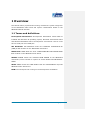
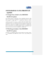
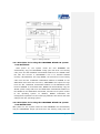
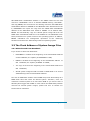
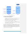
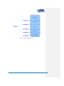
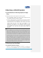
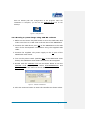
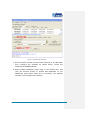
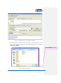
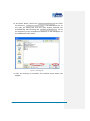
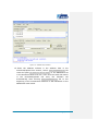
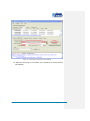
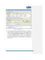
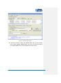
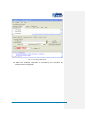
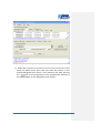
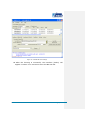
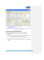
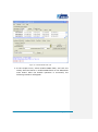
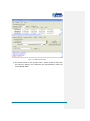
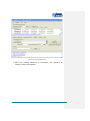
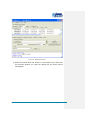
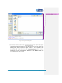
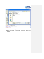
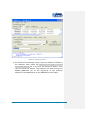
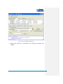
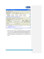
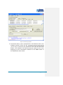
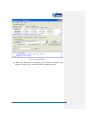
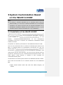
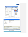
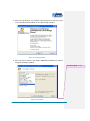
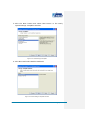
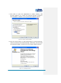
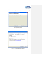
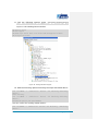
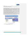
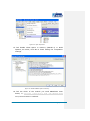
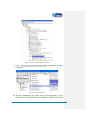
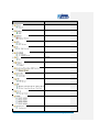
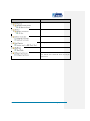
SBC6300x ARM9 Based Single Board Computer WinCE Development Guide Version 1.2 20th Jan 2014 Copyright Statement: SBC6300x and its related intellectual property are owned by Shenzhen Embest Technology Co., Ltd. Shenzhen Embest Technology has the copyright of this document and reserves all rights. Any part of the document should not be modified, distributed or duplicated in any approach and form without prior written permission issued by Embest Technology Co., Ltd Revision History: Version Date Description 1.0 24/10/2009 Original Version 1.1 26/02/2013 First Revision 1.2 20/01/2014 Localisation Table of Contents SBC6300X WinCE 6.0 User Manual. Error! Bookmark not defined. Chapter I. Introduction of the ManualError! Bookmark not defined. 1.1 Terms and definitions ................................................................. 1 1.2 Disclaimer ...................................... Error! Bookmark not defined. Chapter II. Introduction of WinCE 6.0 system ......................... 2 2.1 Image files related to SBC6300X WinCE 6.0 system ......................... 2 2.2 Working principles of SBC6300X WinCE 6.0 system ......................... 2 2.3 The address of SBC6300X WinCE 6.0 system image files in flash ....... 4 Chapter III. Burning of WinCE system .................................... 7 3.1 Introduction to burning of SBC6300X WinCE 6.0 system image files ... 7 3.2 Burn SBC6300X WinCE 6.0 system image through SAM-BA (boot from Dataflash) ..................................................................................... 7 3.3 Burn SBC6300X WinCE 6.0 system image through SAM-BA (boot from NAND flash) ....................................................................................19 Chapter IV. Boot WinCE 6.0 system ...................................... 32 4.1 Boot WinCE system .......................... Error! Bookmark not defined. Chapter V. Customization of WinCE system based on SBC6300X WinCE 6.0 BSP .......................................................................... 33 5.1 Installation of SBC6300X WinCE 6.0 BSP ......................................33 5.2 The compilation of WinCE system based on SBC6300X WinCE 6.0 BSP33 5.3 The compilation of WinCE system based on SBC6300X WinCE 6.0 BSP33 5.4 Modules of SBC6300X WinCE 6.0 BSP driver ..................................43 1 Overview This Manual mainly expounds the burning of WinCE 6.0 system image files of the SBC6300X main board and system customization based on the SBC6300X WinCE 6.0 BSP. 1.1 Terms and definitions Development Workstation: Development Workstation means X86 PC installed with Windows XP operating system, Microsoft Visual Studio 2005 and Windows Embedded CE 6.0 development environment. This PC must have a serial port and a USB port. SPI DataFlash: SPI DataFlash means the DataFlash AT45DB321D-SU (4MB) of SPI interface on the SBC6300X main board. NAND flash: NAND Flash the 8-bit 128MB SAMSUNG K9F1G08UB NAND flash module on the SBC6300X main board. SDRAM: SDRAM means the extended 64MB SDRAM on the SBC6300X main board, which consists of 2 pieces of 16-bit 32MB HY57V581620FTPHKOR. SRAM: SRAM means the 16KB SRAM inside the AT91SAM9263 chip that SBC6300X main board uses. DNW: The serial port tool running on the development workstation. Page | 1 2 Introduction to the WinCE 6.0 system 2.1 Image files related to the SBC6300X WinCE 6.0 system If the WinCE system is customized using the SBC6300X WinCE 6.0 BSP that we provide and the compilation is successfully finished, the system will generate FIRSTBOOT.bin, 6 image EBOOT.bin, files, i.e.: NK.bin , FIRSTBOOT.nb0, EBOOT.nb0, NK.nb0, of which 4 files are usually used in burning processes, i.e.: FIRSTBOOT.nb0, EBOOT.nb0, NK.nb0, NK.bin. The files generated in .nb0 format will finally be burnt to DataFlash or NAND Flash, and they can directly run in SDRAM; while the files in .bin format must first be converted into .nb0 files by EBOOT running on SBC6300X main board nb0, they are then burnt to DataFlash or NAND Flash. 2.2 Working principles of the SBC6300X WinCE 6.0 system At present, our SBC6300X WinCE 6.0 BSP supports two booting modes, i.e.: SPI DataFlash and NAND flash. Below is their rough booting flow chart: Page | 2 Figure 1: Booting Flowchart 2.2.1 Principles for booting the SBC6300X WinCE 6.0 system from DataFlash After power on, the system inside the CPU ROMBOOT will automatically copy the FIRSTBOOT image (the first-level user booting code) from the SPI DataFlash 0x00000000 address to the SRAM inside the CPU and execute it. FIRSTBOOT’s role is to initialize SDRAM memory, SPI DataFlash, and copy EBOOT, the second-level user booting code from the SPI DataFlash 0x00005000 address to SDRAM on the SBC6300X main board and execute it; FIRSTBOOT also copies the Logo from the SPI DataFlash 0x00100000 address of the SBC6300X main board to SDRAM. In its default state, EBOOT will automatically copy the WinCE system image NK from the NAND flash 0x00200000 address to the SDRAM on the SBC6300X main board, and hand over system control to the operating system. In addition, EBOOT undertakes the management operations of the underlying hardware and shares the data settings with the operating system. 2.2.2 Principles for booting the SBC6300X WinCE 6.0 system from NAND Flash After power on, the system inside the CPU ROMBOOT will automatically copy the FIRSTBOOT image (the first-level user booting code) from the Page | 3 SPI NAND flash 0x00000000 address to the SRAM inside the CPU and execute it. FIRSTBOOT’s role is to initialize SDRAM memory, SPI NAND , and copy EBOOT, the second-level user booting code from the NAND Flash 0x00020000 address to SDRAM on the SBC6300X main board and execute it; FIRSTBOOT also copies the Logo from the NAND flash 0x00080000 address of the SBC6300X main board to SDRAM. In its default state, EBOOT will automatically copy the WinCE system image NK from the NAND flash 0x00200000 address to the SDRAM on the SBC6300X main board, and hand over system control to the operating system. In addition, EBOOT undertakes the management operations of the underlying hardware and shares the data settings with the operating system. 2.3 The Flash Address of System Image Files 2.3.1 When booted from DataFlash If you choose to boot from Data flash: FIRSTBOOT is located at the beginning of the 0x00000000 address of SPI DataFlash, the capacity of FIRSTBOOT is 4KB; EBOOT is located at the beginning of the 0x00005000 address of SPI The Logo is saved at the beginning of the 0x00100000 address of SPI DataFlash, the capacity of EBOOT is 200KB; DataFlash; WinCE system image files NK is located in NAND flash in an area of 40MB starting from the 0x00200000 address. The area in NAND flash outside of this 40MB will provide functionality as a NAND flash hard disk under the WinCE system. Therefore, users can customize a WinCE system of no more than 40MB. If you need to store a WinCE system bigger than 40MB or need reduce the NAND flash partition reserved for WinCE system images, please feel free to contact our technicians for assistance. Page | 4 Figure 2: DataFlash Structure 2.3.2 When booted from NAND flash If you choose to boot from NAND flash: FIRSTBOOT is located at the beginning of the 0x00000000 address of the NAND Flash, the capacity of FIRSTBOOT is 4KB; EBOOT is located at the beginning of the 0x00020000 address of the NAND flash, the capacity of EBOOT is 200KB; The Logo is saved at 0x00080000 of the NAND Flash; WinCE system images are located in NAND Flash in an area of 40MB starting from the 0x00200000 address. The area in NAND Flash after the 0x2860000 address will provide functionality for use as a NAND Flash hard disk under the WinCE system. Therefore, users can customize a WinCE system of no more than 40MB. If you need store a WinCE system of bigger than 40MB or need reduce the NAND Flash partition reserved for WinCE system images, please feel free to contact our technicians for assistance. Page | 5 Figure 3: NAND Flash Structure Page | 6 3 Burning a WinCE System 3.1 Introduction to Burning System Image Files The SBC6300X WinCE 6.0 BSP supports two burning modes: 1. Burn FIRSTBOOT, EBOOT and WinCE system image NK using the SAM-BA software provided by ATMEL; 2. Connect VS2005 WinCE 6.0 development environment installed on client development workstation or other TFTP servers (e.g.: CEDownload.exe) to the SBC6300X main board, burn WinCE system image files NK via net cable using EBOOT on the SBC6300X (the EBOOT on the SBC6300X WinCE 6.0 BSP doesn’t support the burning of user booting codes FIRSTBOOT and EBOOT, it can only burn the WinCE system image file NK.bin). Note: If you use EBOOT as the user booting code on the SBC6300X main board to WinCE system image file NK, the actual process will be, EBOOT, the user booting code on SBC6300X main board will first download WinCE system image file NK.bin that VS2005 WinCE 6.0 generates from TFTP server running on the development workstation to the SDRAM on the SBC6300X main board via Ethernet cable, then the file will be converted into NK.nb0 before being burnt to NAND flash. The TFTP server mentioned here can be the server provided in VS2005 WinCE 6.0 development environment or other TFTP servers. Please note that the port parameter of the TFTP server that you use is 980 instead of 69, the standard TFTP port. The software CEDownload.exe, which we will describe in Section 3.4 below is a TFTP server software, which has changed the default TFTP port from 69 into 980. 3.2 Booting from DataFlash 3.2.1 Install the SAM-BA software Install the AT91-ISP v1.12.exe application (located in \03 WinCE 6.0 Kit\04 Tools\) on the SBC6300X CD to your development workstation Page | 7 with the default path and configuration of the program. After the installation is complete, you will see the SAM-BA v2.8 icon on the desktop: Figure 4: SAM_BA Icon 3.2.2 Burning a system image using SAM-BA software 1. Make sure the three-way DIP switch is set to the OFF state and make sure there is no SD card in the SD slot of the SBC6300X. 2. Connect the USB device port (J9) of the SBC6300X to the USB Host of the development workstation using the supplied USB cable. 3. Connect the supplied 12V power supply to the J1 port of the SBC6300X main board. 4. Turn on the power switch (SWITCH B1) of the SBC6300X main board; the SBC6300X main board should now be energized. 5. Double click the SAM-BA v2.8 icon as shown below to run the SAM-BA v2.8 program, and select AT91SAM9263-EK and \usb\ARM0 from the menu as shown below. Figure 5: SAM-BA Initialisation 6. Click the Connect button to enter the interface as shown below. Page | 8 Figure 6: SAM-BA Main Interface 7. Set the boards second and third DIP switches to the ON state then configure the software as shown above (under the DataFlash AT45DB/DCB tab). 8. Select Enable DataFlash (SPI0 CS0) in the Scripts box, and click the Execute button to enable SPI DataFlash on the SBC6300X main board. After this is successful, the SAM-BA interface will resemble the following: Page | 9 Figure 7: SAM-BA Interface After DataFlash is Enabled 9. As shown above, select Send Boot File in the Scripts menu and click the Execute button. An open file dialog box as shown below will display: Comment [ML1]: Chinese Figure 8: Open File Dialog Box Page | 10 10. As shown below, select the FIRSTBOOT_SPIDATAFLASH.nb0 file under the directory \03 WinCE 6.0 Kit\00 Image\ in the SBC6300X CD. In the open file dialog box click the open button, SAM-BA will automatically start burning the FIRSTBOOT_SPIDATAFLASH.nb0 file to the beginning of the 0x00000000 address of SPI DataFlash on the SBC6300X main board. Figure 9: Selecting File 11. After the burning is successful, the window shown below will appear: Page | 11 Figure 10: SAM-BA Main Interface 12. Enter the address 0x5000 in the Address field in the Download/Upload File section, select EBOOT_SPIDATAFLASH.nb0 file under the path \03 WinCE 6.0 Kit\00 Image\ on the SBC6300X CD in the Send File Name text box. Then click the Send File button in the Download/Upload File area, the software will automatically start burning EBOOT_SPIDATAFLASH.nb0 file to the beginning of the 0x00005000 address of SPI DataFlash on the SBC6300X main board. Page | 12 Figure 11: Information to be Entered into SAM-BA 13. After the burning is successful, the interface as shown below will appear: Page | 13 Figure 12: Burning Successful 14. As shown below, enter the address 0x100000 in the Address field in the Download/Upload File area, select the Logo.bin file under the path \03 WinCE 6.0 Kit\00 Image\ on the SBC6300X CD in the Send File Name text box. Then click the Send File button in the Download/Upload File area. The software will automatically start burning the Logo.bin file to the beginning of the 0x00100000 address of SPI DataFlash on the SBC6300X main board. Page | 14 Figure 13: SAM-BA Logo Settings 15. As shown below, select the NAND Flash tab. In the Scripts menu select Enable NAND Flash, and click the Execute button to enable NAND Flash on the SBC6300X main board. Page | 15 Figure 14: Enabling NAND Flash 16. After the enabling operation is successful, the interface as shown below will appear: Page | 16 Figure 15: Operation Successful 17. Select the SBC6300X CD \03 WinCE 6.0 Kit\00 Image \NK.nb0 file in the Send File Name area, then click the Send File button in the Download/Upload File section. The software will start burning the NK.nb0 file to the beginning of the 0x00200000 address of the NAND Flash on the SBC6300X main board. Page | 17 Figure 16: SAM-BA NK.nb0 Settings 18. After the burning is successful, the interface (below) will appear. It takes 3-10 minutes to burn the NK.nb0 file. Page | 18 Figure 17: Burning was Successful 3.3 Booting from NAND Flash 3.3.1 Burn SBC6300X system image through SAM-BA software 1. For installation of the SAM-BA software please refer to Section 3.2.1 , and finish steps 1-6 referring to Section 3.2.2. 2. Set the core board second DIP switch to the ON state. Then as shown below, select the NAND Flash tab in the software window. Page | 19 Figure 18: SAM-BA NAND Flash Tab 3. In the Scripts menu, select Enable NAND Flash, and click the nearby Execute button to enable NAND flash on the SBC6300X main board. After the Enable operation is successful, the following interface will appear: Page | 20 Figure 19: NAND Flash Enabled 4. As shown below in the Scripts menu, select Erase All and click the Execute button; the software will automatically erase the entire NAND flash. Page | 21 Figure 20: Erasing NAND Flash 5. After the erasing operation is successful, the interface as shown in below will appear: Page | 22 Figure 21: NAND Flash Erased 6. Select the Send Boot File button in the Scripts menu and click the Execute button. An open file dialog box as shown below will appear. Page | 23 Comment [ML2]: Chinese Figure 22: Open File Dialog Box 7. As shown below, select the FIRSTBOOT_NAND.nb0 file under the path on the SBC6300X CD in the open file dialog box, then click the Open button. The software will \03 WinCE 6.0 Kit\00 Image\ automatically start burning the FIRSTBOOT_NAND.nb0 file to the beginning of the 0x00000000 address of the NAND Flash on the SBC6300X main board. Page | 24 Figure 23: File Selection 8. After the burning is successful, the interface (below) will appear. Page | 25 Figure 24: Burning Successful 9. As shown in the following image, enter the address 0x20000 in the Address: field. Select the SBC6300X CD \03 WinCE 6.0 Kit\00 file in the text box Send File Name:, then click the Send File button. The software will start burning the Image \EBOOT_NAND.nb0 EBOOT_NAND.nb0 file to the beginning of the 0x20000 address of the NAND Flash on the SBC6300X main board. Page | 26 Figure 25: Burning EBOOT_NAND.nb0 10. After the burning is successful, the following interface will appear. Page | 27 Figure 26: Burning Successful 11. As shown below, enter the address 0x80000 in the Address field. Select the SBC6300X CD \03 WinCE 6.0 Kit\00 Image \Logo.bin file in the Send File Name box, then click the Send File button. The software will start burning the Logo.bin file to the beginning of the 0x80000 address of the NAND flash on the SBC6300X main board. Page | 28 Figure 27: Burning Logo.bin 12. As shown below, enter 0x00200000 in the address field in the software window; select the file \03 WinCE 6.0 Kit\00 Image \NK.nb0 (on the CD) in the Send File Name box, then click the Send File button. The software will start burning the NK.nb0 file to the beginning of the 0x00200000 address of the NAND Flash on the SBC6300X main board. Page | 29 Figure 28: Burning NK.nb0 13. After the burning is successful, the following interface will appear. It takes 3-10 minutes to burn the NK.nb0 file. Page | 30 Figure 29: Burning Successful Page | 31 4 Booting the WinCE 6.0 system 1. Refer to section 3; select the option to boot from DataFlash or NAND flash then burn the WinCE 6.0 system image files. 2. Set the power SWITCH to the ON state, the WinCE system will be booted. Enter the WinCE 6.0 system, the TFTLCD will first display the calibration touch screen as shown below. Page | 32 5 System Customization Based on the WinCE 6.0 BSP Note: To develop a Windows Embedded CE 6.0 operating system using the SBC6300X BSP, you need setup a Windows Embedded CE 6.0 development workstation. This Manual assumes that the Windows Embedded CE 6.0 development workstation software has been installed on Drive F, e.g. the installation path for Windows Embedded CE 6.0 is [F:\WINCE600]. 5.1 Installation of the WinCE 6.0 BSP Unzip the archive located in: SBC6300X CD\03WinCE6.0Kit\01BSP\SBC6300X.rar to the F:\WINCE600\PLATFORM folder of the development workstation. Unzip the archive located location: in: SBC6300X CD\03WinCE6.0Kit\01BSP\ATMEL.rar F:\WINCE600\PLATFORM\COMMON\SRC\SOC on the to the development workstation. Once this is complete, the installation of SBC6300X WinCE 6.0BSP is finished. Compilation of a WinCE system based on the SBC6300X WinCE 6.0 BSP Here we will not describe how to customize a WinCE project based on the BSP in a VS2005 WinCE 6.0 development environment, the user can directly copy the SBC6300X CD\03WinCE6.0Kit\02Project\SBC6300X.rar archive to the directory F:\WINCE600\OSDesigns\ on the development workstation, and unzip this file into the same directory. The user can then directly open the project file SBC6300X.sln (in the F:\WINCE600\OSDesigns\SBC6300X folder), and select (Build-> Build Solution) in VS2005 to start compiling the customized WinCE system. Customisation of a WinCE system based on the SBC6300X WinCE 6.0 BSP This section will describe how to customize WinCE 6.0 in the SBC6300X BSP: 1. Open Visual Studio 2005 and click File->New->Project, as below: Page | 33 Figure 30: Starting a New Project 2. Select Platform Builder for CE 6.0 from Other project types in New Project wizard, enter SBC6300X as the name, (see below) Figure 31: Enter Project Name Page | 34 3. Click the OK button, the system will progress to the next step of the Windows Embedded CE 6.0 OS Design Wizard. Figure 32: OS Design Wizard 4. Click the Next button and select SBC6300X:ARMV4I in Board Support Packages (BSPs): Comment [ML3]: Chinese Figure 33: Select BSP Page | 35 5. Click the Next button and select PDA Device in the newly opened Design Templates window: Figure 34: Select Design Template 6. Click Next and select Mobile Handheld: Figure 35: Select Design Template Variant Page | 36 7. Click Next to open the Applications & Media window, add Internet Explorer 6.0 (under the Internet Browser checkbox) and WordPad in addition to the preselected default options: Figure 36: Add IE 6 and WordPad 8. Click the Next button to open Networking & Communications, remove Personal Area Network(PAN)->Bluetooth and Personal Area Network(PAN)->IraDA from the existing default options. Figure 37: OS Design Wizard Page | 37 9. Click the Next button, then click finish in the OS Design Project Wizard Complete window shown below: Figure 38: Wizard Complete 10. Click Acknowledge to finish the initial customization of the WinCE 6.0 OS. Figure 39: I/O Protocol Driver Security Warning Page | 38 11. Tick the following options under Items Support View->SBC6300X->Core View->other OS->CEBASE->Core OS windows->Catalog Services->USB HOST in the Catalog Items window. USB Function Driver USB Host Support USB Human Input Device (HID) Class Driver->USB HID Keyborad and Mouse USB Storage Class Driver Figure 40: Adding USB Host Support 12. Add the following options following the steps described above: Core OS->CEBASE -> Communication Services and Networking->Networking- -> Communication Services and Networking->Networking- General-> Domain Discovery Core OS->CEBASE General-> Extended DNS Querying and Update(DNSAPI) Here we remove the existing default options: Core OS->CEBASE -> Communication Services and Networking ->Networking- General-> Page | 39 TCP/IPv6 Support Continue to add the following options: Core OS->CEBASE->File Systems and Data Store->Storage Manager->Storage Manager Control Panel Applet Core OS->CEBASE->International->Locale Specific Support-> Chinese (Simplified) ->Fonts->SimSun&NsimSun(Choose 1)->SimSun&NsimSun Core OS->CEBASE->International->Locale Specific Support-> Chinese Specific Support-> Chinese (Simplified) ->GB1803030 Data ConverterCore OS->CEBASE->International->Locale (Simplified) -> Monotype Imaging AC3 Font Compression Device Drivers->SDIO->SDIO Host->SDIO Standard Host Controller Device Drivers->SDIO->SDIO Memory->SD Memory Device Drivers->USB Function->USB Function Clients->Mass Storage Device Drivers->USB Function->USB Function Clients->serial 13. Set compilation type as SBC6300X ARMV4I Release: Figure 41: Setting Compilation Type 14. Click Project->properties in VS2005: Page | 40 Figure 42: Open Properties 15. Tick Enable eboot space in memory (IMAGE=1) in Build Options, as below, click OK to finish editing the compilation settings. Figure 43: Enable EBOOT Space in Memory 16. Tick the driver of the module you need SBC6300X main board, in View->Other Party->SBC6300X:ARMV4I window->Catalog Items View->SBC6300X->Third in VS2005. Page | 41 Figure 44: Select USB Storage Class Driver 17. Click Build->Advanced compiling: Build Commands->Sysgen in VS2005 to start Figure 45: Start Compiling 18. As the compilation may take a long time (depends on the hardware of the development workstation), please wait. After Page | 42 the system compilation is successful, VS2005 will export the following information: Figure 46: System Compilation Successful 19. The moment 6 WinCE 6.0 image files, i.e.: EBOOT.nb0, NK.nb0, FIRSTBOOT.bin, generated EBOOT.bin, FIRSTBOOT.nb0, will NK.bin, under be the F:\WINCE600\OSDesigns\SBC6300X\SBC6300X\RelDir\SBC6300X_ARMV4I_Releas\f older. 5.2 WinCE 6.0 BSP Driver Modules After the SBC6300X WinCE 6.0 BSP is installed and a project based on the BSP is initially customized following the instructions in Section 0, click View->Other window->Catalog >SBC6300X:ARMV4I, Items View->SBC6300X->Third Party- you will see the modules of each driver module of the SBC6300X WinCE 6.0 BSP, you can choose them as required. The table below will describe the functions of each module. Module Function ADC driver. AC97 driver. SC16C554 serial chip driver.. Page | 43 Module Function Buzzer driver. Display driver. Ethernet driver. GPIO driver. I2C driver. I2C EEPROM driver. IO driver. IO key driver. DM9000 driver 6X6 matrix keyboard driver PWM driver. SD card SDIO driver. AT91SAM9263 serial driver TFTLCD driver Touch screen driver. Page | 44 Module Function USB device driver. USB host driver. Bootloader Hive registry. NAND Flash driver. SD card 4 cable SPI driver. Note: SD card SDIO driver and SD card 4 cable SPI driver can only be selected once. Page | 45 Appendix 1: ESD Precautions & Handling Procedures Please note that the board comes without any case/box and all components are exposed. Therefore, extra attention must be paid to ESD (electrostatic discharge) precautions. To effectively prevent electrostatic damage, please follow the steps below: Avoid carpets in cool, dry areas. Leave development kits in their anti-static packaging until ready to be installed. Dissipate static electricity before handling any system components (development kits) by touching a grounded metal object, such as the system unit unpainted metal chassis. If possible, use antistatic devices, such as wrist straps and floor mats. Always hold an evaluation board by its edges. Avoid touching the contacts and components on the board. Take care when connecting or disconnecting cables. A damaged cable can cause a short in the electrical circuit. Prevent damage to the connectors by aligning connector pins before you connect the cable. Misaligned connector pins can cause damage to system components at power-on. When disconnecting a cable, always pull on the cable connector or strain-relief loop, not on the cable itself. Warning: This is a class A product. In a domestic environment this product may cause radio interference in which case the user may be required to take adequate measures. Page | 46 Appendix 2: Technical support & Warranty Embest Technology Co., Ltd. established in March of 2000, is a global provider of embedded hardware and software. Embest aims to help customers reduce time to market with improved quality by providing the most effective total solutions for the embedded industry. In the rapidly growing market of high end embedded systems, Embest provides comprehensive services to specify, develop and produce products and help customers to implement innovative technology and product features. Progressing from prototyping to the final product within a short time frame and thus shortening the time to market, and to achieve the lowest production costs possible. Embest insists on a simple business model: to offer customers high-performance, low-cost products with the best quality and service. 2.1 Technical support service Embest provides one year of free technical support for all products. The technical support service covers: Embest embedded platform products software/hardware materials Assistance to customers with regards to compiling and running the source code we offer. Troubleshooting problems occurring on embedded software/hardware platforms if users have followed the instructions provided. Judge whether a product failure exists. The situations listed below are not covered by our free technical support service, and Embest will handle the situation at our discretion: Customers encounter issues related to software or hardware during their development process Issues occur when users compile/run the embedded OS which has been modified by themselves. Page | 47 Customers encounter issues related to their own applications. Customers experience problems caused by unauthorised alteration of our software source code 2.2 Maintenance service clause 1. Product warranty will commence on the day of sale and last 12 months provided the product is used under normal conditions 2. The following situations are not covered by the warranty, Embest will charge service fees as appropriate: Customers fail to provide valid proof of purchase or the product identification tag is damaged, unreadable, altered or inconsistent with the product. Products are subject to damage caused by operations inconsistent with their specification; Products are subject to damage in either appearance or function due to natural disasters (flood, fire, earthquake, lightning strike or typhoon) or natural aging of components or other force majeure; Products are subject to damage in appearance or function due to power failure, external forces, water, animals or foreign materials; Products malfunction due to disassembly or alteration of components by customers, or repair by persons or organizations unauthorized by Embest Technology, or alteration from factory specifications, or configured or expanded with components that are not provided or recognized by Embest Technology; Product failures due to the software or systems installed by customers, inappropriate software settings or computer viruses; Products purchased from unauthorized merchants; Embest Technology takes no responsibility for fulfilling any warranty (verbal or written) that is not made by Embest Technology and not included in the scope of our warranty. Page | 48 3. Within the period of warranty, the cost for sending products to Embest should be paid by the customer. The cost for returning the product to the customer will be paid by Embest. Any returns in either direction occurring after the warranty period has expired should be paid for by the customer. 4. Please contact technical support with any repair requests. Note: Embest Technology will not take any responsibility for products returned without the prior permission of the company. 2.3 Basic guidelines for protection and maintenance of LCDs 1. Do not use finger nails or other hard sharp objects to touch the surface of the LCD 2. Embest recommends purchasing specialist wipes to clean the LCD after long time use, avoid cleaning the surface with fingers or hands as this may leave fingerprints or smudges. 3. Do not clean the surface of the screen with unsuitable chemicals Note: Embest do not supply a maintenance service for LCDs. We suggest the customer immediately checks the LCD once in receipt of the goods. In the event that the LCD does not run or shows no display, the customer should inform Embest within 7 business days of delivery. 2.4 Value Added Services We will provide following value added services: Page | 49 Driver development based on Embest embedded platforms for devices such as: serial ports, USB interface devices, and LCD screens. Control system transplantation, BSP driver development, API software development. Other value added services including supply of power adapters and LCD parts. Other OEM/ODM services. Technical training. Please contact Embest with any technical support queries: http://www.embest-tech.com/contact-us.html Page | 50