1
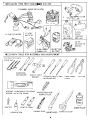
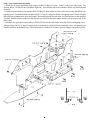
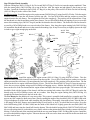
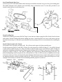
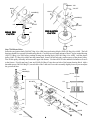
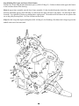
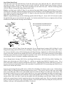
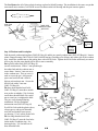
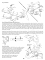
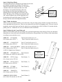
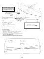
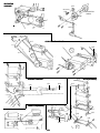
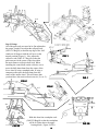
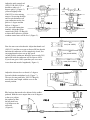
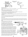
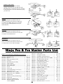
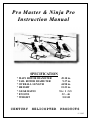
P r o M aster &
Instruction
Ninja Pro
Manual
SPECIFICATION
* MAIN ROTOR DIAMETER
* TAIL ROTOR DIAMETER
* OVERALL LENGTH
* HEIGHT
* GEAR RATIO
* ENGINE
* WEIGHT
CENTURY
HELICOPTER
49.10 in.
9.37 in.
44.90 in.
15.23 in.
9.6 : 1 : 5.5
32 ~ 46
5.8 LB
PRODUCTS
9 / 1995
Building Instructions for Ninja Pro
Helicopter Kit
Congratulations you have just purchased the finest 30-46 size RC helicopter model on the market. The Ninja
Pro and Pro Master series of helicopters feature cutting edge design along with state of the art materials used
throughout. Modern composite G-10 is used for the side frames for strength and to minimize vibration. An all
metal swashplate, metal washout and metal main rotor head are used to give precise control and handling
characteristics. Your Ninja Pro has been carefully researched and developed to give the highest performance
level achievable with present technology. We are constantly reevaluating our line of kits as technology advances in order to give you the highest degree of performance at all times. The instruction manual is divided
into twenty sections.. The parts bags have also been separated into eleven different numbered bags. The bags
should be opened in their numbered sequence with the exception of bag # eight as this is the hardware bag
and will be used in all steps.
Explanation:
* This instruction is written for 4 types of Ninja series, Ninja Pro 30,
Ninja Pro 46, Ninja Pro 30 Master and Ninja Pro 46 Master.
* Use locktite at the point where
* Use oil at the point where
this mark is shown.
this mark is shown.
* Special attention at the point where
this mark is shown caution !
OPERATE YOUR NINJA PRO HELICOPTER SAFELY
Your new Ninja Pro helicopter is state of the are using proven design techniques and the best materials
available. This is done for two reasons, first to give you the highest quality helicopter available and second,
to insure it’s SAFE operation. It is imperative that the instructions be followed carefully during construction.
This will insure that your Ninja Pro is properly assembled and safe to operate. We are not responsible for
any damages or injuries caused by improper building, careless flying practices or the use of nonfactory parts. We can not stress the importance of using ONLY factory replacement parts for your Ninja Pro.
Every part in your Ninja Pro Kit has been thoroughly tested and made from the best materials. After market
parts may substandard and will compromise the safety of yourself and others at flying field. While flying,
always do so away from any obstacles. This includes trees, power lines, animals, people...... in the other
words, ANYTHING that can be hit if your model should go out of control. It is strongly recommended that
you NEVER go flying alone, a second person can warn you if anything comes into your flying area.
2
ED
3
Step 1 Lower side Frame Assembly
1. Attach the 90 degree aluminum angle support (2002-079 Bag #1) to the “inside” of the lower side frame. See
drawing below. Do this for the left and the right side. Each bracket is held on with three M3x8 cap head bolts and
Locknuts.
2. Attach two plastic battery tray mounts (2002-055 Bag #4) between the two lower side frames using four M3x8 selftapping screws. Install the battery tray plate (2002-113 Bag #1) using four M3x8 self-tapping screws. Please note that
there has been a change in the servo tray length. The mounts must be located at the very front and rear of the available
locations. Double check to make sure that the hole provided for the front cannot mount is on the proper side of the
battery tray.
3. Attach the two gyro plate cross members (2002-055) between the side frames using four M3x8 self-tapping screws.
Add gyro plate (2002-119 Bag #1) on top of the cross members with four M3x6 countersink screws. An optional gyro
location would be on the battery tray. This should only be considered if a center of gravity change is deemed necessary.
4
Step 2 Engine/Clutch Assembly
Slide the cooling fan (2002-115 Bag #1 for 30-size and 2002-097 Bag #2 for 46-size) onto the engine crankshaft. Then
slide the starter pulley (2002-149 Bag #4) on top of the fan. Add the engine nut and tighten it, but do not use any
Locktite. Install the centrifugal clutch (2002-147 Bag #4) to the pulley with two M3x10 bolts. Put the ball bearing
(2002-103 Bag #4) in the center of the clutch.
For 30-size engine: Install the engine to the engine mount (2002-099 bag #2) using four M3x12 bolts. Take the engine
assembly and slide it into the side frames from the top side. Use four M3x10 bolts and four washers to secure the
engine mount to the side frames. Do not tighten the four bolts completely. The position will be adjusted later. Drop
the fan shroud over the fan and between the lower frames. Use two M3x8 Philip head self-tapping screws to secure the
starter belt retaining clips (2002-057 bag #8) and the fan shroud to the side frames. The front end of the fan shroud is
secured by a M3x8 Philip head screw on each side of the frames. Now, hang the engine starting belt (2002-109 Bag
#4) around the fan shroud and secure in the starter belt retaining clips. It may be necessary to slightly squeeze the clips
in order to get a tight enough grip on the belt.
M3X10
103
147
46 CUT THIS
AWAY
M3X10
M3X10
103
115
MASTER
302
147
057
149
097
151
M3X8 Self
Tapping
096
101
099
M3X8 Self
Tapping
057
098
M3X6
bent here to fit
101
M3X12
M3X12
For 46-size engine: Install the engine to the engine mount (2002-101 Bag #2) using four M3x12 bolts. Take the
engine assembly and slide it into the side frames from the top side. Use six M3x12 bolts and six washers to secure the
engine mount to the side frames. Do not tighten the four bolts completely. The position will be adjusted later. The fan
shroud for the 46-size engine is different from the 30-size. The 46-size shroud (2002-107 bag #2) comes in two pieces.
Screw the two pieces together using two M3x8 Philip self-tapping screws. Add the fan bracket (2002-098 Bag #2 )
between the rear of the fan shroud and the engine mount and adjust the fan to proper height. The bottom of the fan
should be flush with the bottom of the shroud. Add the two starting belt retainer clips (2002-057 Bag #8) on the fan
shroud using two M3x8 Phillips screws and two washers. Now hang the engine starting belt (2002-109 Bag #4)
around the fan shroud and secure the belt in the clips.
The Pro Master has the addition of a top start system. This system is assembled and installed as a complete unit.! Do
not use any ABC engine for shaft start system. Start by sanding the inside of the clutch bell (2002-303 BAG #4M) with
220 grit sandpaper to aid the bond when installing the clutch lining. Thoroughly clean with solvent. Trim the liner so
it fits snugly in the bell. Remove and reinstall using JB weld epoxy or slow CA to hold the liner in place. Press the
4x9x4 ball bearing (2002-103 BAG #4M) into the inside of the clutch bell. Lightly grease the start shaft (2002-306
BAG #4M) and insert into the clutch bell from the bottom. Take the double bearing block (2002-307 BAG #4M) and
slip over the pinion shaft. It is advisable to use a little Locktite on the pinion shaft where it makes contact with the ball
bearing. Clean off the end of the start shaft and slide the one way start adapter (2002-304 Bag #4M) in place. Install the
set-screws that hold the adapter in place. Take note that one of the set-screws must seat on the flat on the start shaft and
Locktite must be used.
5
Step 3 Installing the Rate Gyro
Use two layers of 1/8 inch thick double-sided foam tape to install the electronic rate gyro to the gyro mounting plate.
The double sided tape can be found at your local hobby shop or at hardware stores. Use the same procedure if you
intend to mount the gyro on the battery tray.
M3X16
M3X8 S/T
109
3X6 SET
SCREW
M3NUT
105
3X6 SET
SCREW
066
068
067
M3X8 S/T
M3X10(30)
M3X12(46)
M3X8 S/T
Step 4 Landing Gear
Attach the two landing gear struts (2002-067 Bag #1) onto the lower frames using four M3x16 bolts 3mm Lock-nuts
and washers. Slide the landing skids into the landing gear struts. Install four M3x6 set screws to the struts to prevent
the skids from moving. It is advisable to pre-thread the struts by running a M3x8 screw into them before installing the
skids.
Step 5 Collective and Cyclic Control
Now put the lower side frame assembly aside. We will start on the upper side frame assembly now.
Fit the elevator axle (2002-153 and 2002-155 Bag #3) to the elevator lever (2002-069 Bag #3). Use a M3x5 bolt and
a small washer to hold each axle; use a drop of Locktite on the M3x5 bolt. Use two steel ball end (2002-229 Bag #3)
and locktite to hold the steel balls in place. Install a plastic bushing (2002-072 Bag #3) onto each of the two collective
pitch levers (2002-071 Bag #3). The 2002-072 bushings can be replaced by optional ball bearings 2002-070. The
plastic bushing flange must rest against the face of the pitch lever. If not, it will be necessary to slightly bevel the edge
of the hole in the lever. Please note that all the plastic bushings should rotate freely on their mating shafts. If not than
the bushings should be reamed out slightly until they do. This can easily be done by rolling some 400 grit wet or dry
sandpaper and working it in and then out of the bushing until the proper fit is achieved.
WASHER(S)
M3X5
WASHER(S)
153
229
229
155
229
069
155
072
153
(070 BALL
BEARING
OPTION)
069
071
6
071
229
071
Step 6 Upper Main Frames Assembly
Fit the elevator control lever set and collective control axle (2002-157 Bag #3)between the top left and top right side
frames (2002-117 Bag #1). Press a plastic flanged bearing (2002-059 Bag #3) for the collective control lever axle into
inside of each side frame.The shorter elevator axle should be on the left side of the helicopter. Install two main bearing
blocks (2002-083 Bag #4 or Bag #4M) onto the top side frames using four M3x35 bolts and four 3 mm nuts. The top
bearing block should have the ball bearing facing up. The bottom bearing block should have the ball bearing facing
downward. After insert the collective control lever axle into the flanged bearing. Add the collective lever (2002-071
Bag #3) to the collective axle. The lever needs to slide onto the elevator axle (2002-153 and 2002-155 Bag #3) with
the flange bearing facing toward the elevator lever. Please see the drawing.
The 2002-059 bushings can be replaced by optional ball bearings (2002-061). Please note once again that these
bushings or ball bearings must move freely and with minimal freeplay in order for your helicopter to operate properly.
It is imperative that the retaining screws be set at the proper tension. Too tight will bind the bearing and too loose will
create unwanted freeplay. Fit the plastic tail boom holders (2002-085 Bag #4 or Bag #4M) in-between the upper side
frames. Also add the tail rotor servo mount plate (2002-073) outside the left side frame. The tail boom holders and
servo mount are held by four M3x35 bolts and four nuts. Do not tighten the four nuts and bolts completely. They will
tightened later, after the tail boom is installed.
083
125
M3X35
071
M3X8
155
WASHER(S)
153
059
157
083
071
M3X8
WASHER(S)
117
125
061
(OPTION
BALL BEARING)
WASHER(S)
117
059
071
M3X8
071
059
117
WASHER(S)
M2 NUT
M3X6
M3X8
075
239
M2 NUT
239
2X10
Take the Y- shaped push-pull collective lever and install the 5mm control balls (2002-239 Bag #8) using M2x10
screws and 2mm nuts. Now add the lever (2002-075 Bag #1) on top of the right side aluminum arm (2002-071 Bag
#3). Use a M3x8 bolt and washer to secure the Y-shaped lever at the collective axle, and a M3x6 bolt to secure the Yshaped lever to the 2002-071 arm. Install two M3x6 flanged plastic bushings (2002-160 Bag #3) The 2002-160 bushings can be replace by optional ball bearing 2002-022 on each 90 degree bell crank (2002-159 Bag #3). Install two
steel balls onto each bell crank using two M2x8 bolts, take care not to have any excess bolt protruding the opposite
side of the bell cranks. There are two 90 degree bell cranks, do this for both left and right side bell cranks. Slide a 90
degree bell crank onto the left side elevator axle (2002-155 Bag #3) Use a M3x10 bolt and Locktite to retain the bell
crank onto the elevator control axle. Do not overtighten this M3x10 bolt; the bell crank should be able to pivot freely,
but there should not be any free play.
7
Now, install a similar 90 degree bell crank to the right side. Install the steel elevator bell crank (2002-161 Bag #3) on
the right side elevator axle (2002-153 Bag #3). We suggest that you file a flat on the elevator axle where the set screw
makes contact. Put a 3x3mm set screw in the steel bell crank. Do not tighten the set screw very tightly yet, because the
exact angle will be adjusted later. When permanently tightened be sure to use a drop of locktite on the elevator bell
crank. Fit the swashplate anti rotation bracket (2002-077 Bag #3) between the upper side frames. Fit two M3x35 bolts
through the frames and the bracket. Secure them with two M3 nuts. Do not overtighten as this will only distort the
frames.
077
085
129
ROUGHEN INNER
SURFACE
161
M3 NUT
M3
NUT
160
M3X6
127
SET SCREW
159
239
2X8
M3X35
JB WELD EPOXY
OR SLOW CA GLUE
JB
073
160
2X8
239
022
BALL
BEARING
OPTION
M3X35
159
M3X10
WASHER(S)
Clutch Bell Assembly
Roughen the inner surface of the clutch bell (2002-127 Bag #4 or #4M) with #220
grit sand paper. Then, clean off the debris. Trial fit the clutch lining (2002-129
Bag #4 or #4M) to the clutch bell, make sure it fits snugly. Once you are
satisfied, then remove the lining and permanently glue it back in using JB weld
Epoxy, or slow CA glue. Fit the clutch bearing (2002-131 Bag #4 or 4M) and
block (2002-081 Bag #4 or #4M) in-between the upper side frames. The ball
bearing should face downward. Use two M3x35 bolts to secure the bearing block
in place. Insert the clutch bell in the clutch bearing. It is recommended to apply
a little locktite to the pinion shaft where it inserts into the bearing.
The Pro Master has the addition of a top start system. This system is assembled
and installed as a complete unit. Start by sanding the inside of the clutch bell
(2002-303 Bag #4M) with 220 grit sandpaper to aid the bond when installing the
clutch lining. Thoroughly clean with solvent. Trim the liner so it fits snugly in the
bell. Remove and reinstall using JB weld epoxy or slow CA to hold the liner in
place. Press the 4x9x4 ball bearing (2002-103 Bag #4M) into the inside of the
clutch bell. Lightly grease the start shaft (2002-306 Bag #4M) and insert into the
clutch bell from the bottom. Take the double bearing block with ball bearing
(2002-307 bag #4M) and slip over the pinion shaft. It is advisable to use a little
Locktite on the pinion shaft where it makes contact with the ball bearing. Clean
off the end of the start shaft and slide the adapter (2002-304 Bag #4M) in place.
Install the set screws that hold the adapter in place. Take note that one of the set
screws must seat on the flat on the start shaft and Locktite must be used. Slide the
assembly into place and secure the bearing block to the frames with two M3x35
screws and nuts. Take note that the heads of these bolts must be on the same side
as the Y shaped collective bell crank.
8
308
3X6 SET
305
OPTION
309
103
301
307
131
303
103
306
304
OPTION
302
308
M3x35
3X6 SET
M3x35
WASHER(S)
WASHER(S)
081
M3 NUT
M3 NUT
131
307
NINJA PRO
C LU T C H
PRO MASTER
CL UTCH
127
303
306
Step 7 Tail Rotor Drive
Insert the steel pinion shaft (2002-087 Bag #4 or #4M) into two bearing blocks (2002-081 Bag #4 or #4M). The ball
bearings should face upward for both bearing blocks. Carefully smear a small amount of slow CA glue around bearing
(2002-131 Bag #4 or 4M) before pushing bearing into bearing block (2002-081 Bag #4 or #4M). Add the plastic
pulley (2002-133 Bag #4 or #4M) onto the pinion shaft. Insert a M3x8 bolt and a washer on top of the plastic pulley.
Now fit this pulley assembly in-between the upper side frames. Use three M3x35 bolts and three locknuts to secure it
to the frames. Fit a 40 mm long 3 mm stud (2002-094 Bag #3) into the rear hole of the bottom bearing block. Add a
threaded spacer (2002-091 Bag #3) on each side of the 3 mm stud. Leave this assembly slightly loose so you can adjust
the gear mesh later.
M3X8
WASHER(S)
133
131
133
M3 NUTS
091
081
087
M3X35
131
094
081
091
M3X35
094
9
M3X35
Step 8 Mating The Upper and Lower Main Frames
Find the four 26 mm long threaded aluminum spacers (2002-093 Bag #3). Fit them in-between the upper side frames
in the locations shown in the drawing.
Mate the upper frame assembly onto the lower frame assembly. Fit the clutch bell onto the clutch first. Add eight 14
mm long aluminum spacers (2002-089 Bag #3) in-between the upper and lower side frames. See drawing for their
locations. Use eight M3x25 bolts to go through these eight spacers. Then add two M3x8 bolts to the two spacers that
are on the pulley bearing block. Use blue Locktite on these bolts.
Ninja Pro don’t forget the engine starting belt (2002-109 Bag #4) Or if building a Pro Master don’t forget to grease the
uniball at the base of the start shaft.
093
091
089
093
093
089
089
M3X25
089
M3X8
109
089
093
093
M3X25
M3X25
089
089
M3X25
M3X8
M3X25
M3X25
M3X25
M3X25
10
Step 9 Main Rotor Head
Insert the metal center hub (2002-003 Bag #5) into the metal center yoke (2002-001 Bag #5). Add a M3x8 bolt on
each side of the yoke. Use blue Locktite on the two bolts. (2002-001, 2002-003) Smear some Vaseline on the two
rubber dampers (2002-011 Bag #5). Then insert one damper on each side of the yoke. Slide the feathering spindle
(2002-005 Bag #5) through the rubber damper and the yoke.
Find the two blade grips (2002-007 Bag #5) note that the four main blade bearings (2002-008 Bag #5) are preinstalled in the blade grip. Add the metal pitch control arm (2002-009 Bag #5) onto the blade grip using a single M3x6
bolt. Add the steel pitch control ball stud (2002-231 Bag#1) to the pitch control arm (2002-009 Bag #5). Use Locktite
on the pitch are and pivot control ball.
Slide the completed blade grip onto the feathering spindle (2002-005 Bag #5). Insert a M3.5x12 bolt and a washer
through the blade grip to secure the hub to the spindle. Use Locktite on this bolt ! Do not over tighten as this will only
mushroom the shaft and make bearing removal difficult.
M3x8
CN2135 HEAD BUTTON (PURPLE)OPTION
CN2136 HEAD BUTTON (GOLD)OPTION
001
M3x8
011
005
M3X25
003
CN2122 CARBON
STIFFENER FOR
FLY BARS
(OPTION)
231
005
008
M3 NUT
M3X6
007A
007
009
008
WASHER(S)
043
M3 NUT
3.5X12
Slide the seesaw (2002-017 Bag #5) onto the center hub. Fit two flanged plastic bearings (2002-160 Bag #3) or the
flanged ball bearings (2002-022 OP) if you are building a Ninja pro master , into the center hole of the seesaw. Secure
the seesaw to the hub by using a M3x6 bolt through each flanged bearing. Tighten the two M3x8 bolts sufficiently to
remove all free play, but the seesaw should still be able to move smoothly ! Use Locktite on the bolts. On this and the
following steps it cannot be stressed enough the importance of the seesaw and mixing arms pivoting freely without
excessive play. The use of Locktite is mandatory during these steps.
Fit two flanged plastic bearings (2002-160) or non-flanged ball bearings (2002-022A Bag #4M) if building a Pro
Master onto each mixing arm (2002-019 Bag #5). Add the two mixing arms (2002-019) onto the seesaw. Use a
M3x10 bolt with Locktite to secure the mixing arm to the seesaw. Tighten the M3x10 bolts sufficiently to remove all
free play, but the arms should still be able to move smoothly. Fit steel ball (2002-239) onto mixing arm (2002-019) use
M2x8 screw with nut and Locktite.
Insert two plastic flanged bearing (2002-160) or (2002-022A) if building a Pro Master on the seesaw. Slide the flybar
(2002-015 Bag #10) through the flanged bearings and the seesaw ! Use a ruler to check to make sure equal length
sticks out on either side of the seesaw. Add a flybar control arm (2002-013 Bag #5) on either side of the seesaw. Coat
the threads of each M3x6 set screw with Locktite, then fit a set screw inside each control arm. Make sure both arms are
level ! Insert a 3mm locknut into the underside of each control paddle (2002-253 Bag #5) Then screw the paddles
onto the flybar. Wick some thin CA glue into the paddle hole after threading it onto the flybar ! Make sure the two
paddles are at same distance from the control arm and are level with the control arms. This is an extremely important
step you can follow the picture to cut a flybar jig template. Check the flybar balance by letting the seesaw pivot on its
bushings. Add tape to the light paddle until balance is achieved.
11
The Pro Master has all of these plastic bearings replaced with ball bearings. The installation is the same except that
some small micro washers 3x4.5x0.5T are used in-between the ball bearing and the part it mates against.
CUT A FLY BAR JIG TEMPLATE
MASTER
USE 022
HERE
SOME THIN
CA GLUE
013
M3X3
230
MAKE SURE
PADDLES & ARM
ARE LEVEL
017
160
230
015
160
019
160
M3x6
013
M2
NUT
253
230
160
CN2029A
FLY BAR
WEIGHTS
(OPTION)
M3X10
239
M2X8
MASTER
USE 022A
HERE
Step 10 Washout and Swashplate
Find the metal washout mixing base (2002-021 Bag #6) and the two metal washout arms (2002-023 Bag #6). Insert a
plastic flanged bearing (2002-160) Or 2002-160 ball bearing if building a Pro Master onto either side of the washout
arm. Attach the washout arm to the mixing base with a M3x10 bolt. Tighten the M3x10 bolts sufficiently to remove
all free play, but the arms should still be able to move smoothly.
Put a plastic radius link (2002-025 Bag #5)
on each washout arm. Slide a 2 mm pin through
the radius link and the washout arm to
secure them. Insert a 3 mm set screw
PRO MASTER
in the washout arm. This set screw is
230
023
121
used to secure the pin. Add a metal
spacer and steel ball and a M2x10
022A
230
bolt on each washout arm. Secure the
M2x10 bolt with a 2 mm nut
(2002-239 Bag #8).
022A
021
Fit three short threaded steel balls
(2002-229 Bag #3) onto three outside
4X4 SET
SCREW
025
arms on the swashplate ! Use Locktite
on all these threaded balls. Be careful
M3X3
SET
not to scratch or overtighten the balls.
023 160
M3X16
They are easily damaged during
installation. For the swashplate
160
antirotation arm (2002-032 Bag #6)
M3X10
M2X12
fit a M3x16 bolt with the plastic sleeve,
239
229
M2 NUT
a brass spacer, and special threaded
032
steel ball and another brass spacer;
226
see drawing ! Use Locktite on the bolt.
226
Fit four long threaded steel balls
(2002-226 Bag #5) onto the four holes
229
229
on the inside swashplate ring. See
031
drawing below. Use Locktite on all
these threaded balls.
12
Step 11 Main Gear and Main Shaft
Slide the aluminum main shaft stopper (2002-123 Bag #6)
onto the main shaft from the bottom. Hold the plastic
main gear (2002-135 Bag #6) underneath the main rotor
shaft bearing block. Slide the main rotor shaft (2002-121
Bag #6) from the top through the bearing blocks and into
the main gear. Install a M3x20 bolt through the main
gear auto rotation hub and through the main shaft and
secure with a 3mm Lock-nut. Note that the end of the
shaft with the most distance between the hole and the
end is the top end of the shaft. Insert two 3x3 mm set
screws into the mast stopper (2002-123) and tighten
them. Make sure the main shaft has nofreeplay up or
down.
Slide the swashplate and the washout assembly onto
the main rotor shaft. Snap the two radius links
(2002-025 Bag #6) onto the inner swashplate
long steel balls (2002-226) 180 degrees from one
another. Add the washout retaining block (gold part
with two steel pins) with the pins pointing downward.
Temporarily use a 4x4mm set screw to secure this part
to the main shaft. Then, add the main rotor head on the
shaft. Insert a M3x20 bolt and locknut through the
M3 NUT
main rotor hub and shaft, and tighten it.
Step 12 Tail Rotor System
Tail Rotor Gearbox
Install the right side plate (2002-185 Bag #7)
onto the gearbox housing (2002-187 Bag #7)
with two M3x6 bolts.
M3X6
Fit the tail rotor drive
shaft (2002-193 Bag #7)
M3X25
and a thin (2002-187 Bag #7)
spacer to the right tail plate. M3X6
Now fit the tail rotor drive
belt through the hole in
187
the tail rotor gearbox
185
housing (2002-187),
197
then loop the tail rotor
drive belt (timing belt)
(2002-183 Bag #4 or 4M)
183
around the tail pulley (2002-193).
187
Add the left side tail plate to the tail
gearbox housing using two M3x6 bolts.
Fit guide pulley (2002-189 Bag #7) and two
thick (2002-187 Bag #7) spacers between the
side plates. Use a M3x25 bolt through the side
plates and through the guide pulley to hold it in
place ! It is extremely important to use Locktite
to all screws that thread into a tapped hole in this step.
135
123
3X3
SET
136
M3X20
M4X10
187
M4X6
187
189
M3X6
187
185
185
M3
NUT
M3X6
M3X6
M2x10
230
M2 NUT
191
M3X10
13
Tail Rotor Blade Grip
M3
Sliding Tail Rotor Pitch Control Mechanism
207
NUT
Slide a ball bearing (2002-209 Bag #7) onto the
tail hub (2002-199 Bag #7) followed by a
M2 NUT
M3X16
spacer (2002-211 Bag #7) then
another bearing. Secure the
bearings and spacer to the
193
hub with a small washer
M3
and a 3mm lock-nut. Repeat
NUT
for the next side. Fit the tail blade
203
202
grips (2002-207 Bag #7) to the bearings
209
M2X10
with four M2x10 screws and nuts ! Note
204
211
201
that one of the grip halves has a nub for the
205
235
pivot ball to be mounted to the grip. Repeat for the
209
204
next side. Attach a pivot ball on each assembly with
a M2x10 screw and nut.
202
Install a ball bearing (2002-204 Bag #7) on either
199
205
203
side of the tail pitch plate housing
(2002-205 Bag #7). Insert the tail
235
pitch plate inner sleeve (2002-203
Bag #7) into the tail pitch plate
M3X3
housing. Note that the pivot pin is
SET
203
offset and the brass slider must be
JB WELD
inserted into the side with less distance
HERE
201
between the pin and housing edge. .
204
204
Attach the tail pitch plate (2002-201 Bag #7)
228
to the brass tail pitch slider. Press the locking
ring onto the brass pitch slider to hold the pitch
control plate in place. It is advisable to add some
JB Weld epoxy to the locking ring for some added security. Add two small plastic ball links (2002-235 Bag #8) on the
tail pitch control plate. Secure them with (2002-202Bag#7) special screw and pin, slide the entire assembly onto the
tail rotor shaft. Attach the tail pitch lever (2002-191 Bag #7) to the tail rotor gear box with a M3x10 bolt two micro
shims (2002-230 Bag #5) and a lock nut. The steel pin on the tail rotor control housing (2002-205 Bag #7) fits into the
steel ball pressed into the end of the bell crank.
Fit the tail rotor hub (2002-199 Bag #7)) with the tail grip onto the tail rotor shaft (2002-193 Bag #7). Put two 3x3mm
set screws in the tail rotor hub, and use them to secure the hub to the shaft. Use Locktite on these set screws.
Fit the tail rotor blades to the blade holders with a 3mm washer on each side of the blade. Secure each blade with a
M3x16 bold and a 3mm nut.
NOTE: make sure the tail blades are facing the proper direction
Step 13 Tail Fins
Put the two half pieces of plastic fin mount (2002-085 Bag #4 or 4M)) on the tail boom (2002-173 Bag #10). Put the
horizontal fin (2002-175 Bag #1)) on top of them Insert two M3x35 bolts through the fin and the plastic mounts. Add
the two tail boom support rods (2002-179 Bag #10) under the plastic mount (2002-085 Bag #4 or 4M). Use two M3
lock nuts to secure all of them, but do not tighten them completely, yet. We will tighten them later.
Slide three tail pushrod guides (2002-171 Bag #4 or 4M) onto the tail boom: two are in front of the horizontal fin, and
one is behind the horizontal fin.
Fit the two plastic mounts (2002-085 Bag #4 or 4M) for the vertical fin (2002-177 Bag #1) on the tail boom. Add the
vertical fin. Insert two M3x35 bolts through the fin and the plastic mounts. Secure them with two 3 mm locknuts.
14
Step 13 Tail Fins
M3x35
175
171
M3 NUT
177
085
171
173
171
223
179
RIGHT !
085
WRONG !
(TOO TIGHT)
085
M3 NUT
085
M3X35
Step 14 Mating Tail Boom to the Main Frames
Feed the tail drive belt (2002-183 Bag #4) through the tail boom starting with the end with two holes. A piece of wire
with a hook bent into it works well for pulling the belt through. Fit the tail boom (2002-173 BAG #10) into the upper
side frames. Loop the drive belt onto the front pulley. The belt should have a 90 degree turn inside the tail boom !
Check to make sure when the main rotor is turning in the clockwise direction (viewed from the top), the tail rotor
should turn counter-clockwise when viewed from the right hand side. Adjust the belt tension by pulling on the tail
boom. Do not over tighten the belt, it should not be too loose so the belt slips. Slowly, tighten the four M3x35 bolts
that hold the tail boom.
Attach the front of the tail boom support rods to the lower main frames. Use two M3x8 bolts and a 57mm threaded
cross member (2002-095 Bag #3) to secure the front of the tail boom support rods to the frames. Mount the aft end of
the boom-struts to the horizontal fin mounts, making sure the horizontal fin is level tighten the two M3x35 bolts
holding the horizontal fin and fin clamp together.
179
215
171
095
M3X10
173
Step 15 Fuel Tank
Assemble the fuel tank (2002-063 Bag #9) carefully according
to the drawing shown below. Use caution while bending the
brass tubing. Do not use any pliers as this will kink the
tubing use your hand and make a smooth flowing bend
to avoid kinking. Add one strip of double sided foam
tape to the top surface of the tank so it will make
contact with the gyro plate mount. Slide the tank
into the side frames from the right hand side.
The fuel line should come out of the right
hand side of the helicopter.
15
Double sided
foam tape
063
From muffler
pressure fitting
To engine carburetor
Step 16 Main Rotor Blades
The rotor blades that are included in your Ninja Pro kit come
pre-finished and require no building. They however
should be checked for balance before use. If you have
a balancer follow the instructions that came with
the balancer. Next attach the blades to the rotor
head. Balance the Rotor head and blades on two
drinking glasses suspending the whole unit by the
flybar. The heavy side will hang lower than the light
side. Add self-adhesive tape on the light blade on a
location that will result in the proper CG shift. Add
the tape until the rotor head hangs horizontally.
CUT THIS
WHITE SHRINK
COVER OFF
THEN USE THIN
CA GLUE HERE
Step 17 Radio Installation
All five servos are mounted with the screws that came with your radio system with the exception of the aft two
screws that hold the elevator servo. These two are replaced by two M3x8 self tapping screws. They are screwed
trough the cutouts in the frame and into the plastic servo mounting plates (2002-169 BAG #3) located with the
plastic parts tree. Mount the five servos as illustrated in the instructions.
Step 18 Making Up the Control Push rods
Make up all the control push rods according to the specified length shown in the drawing. Please note that these
dimensions are from end to end of the plastic rod-end and are only guidelines. You will have to fine adjust them
according to your particular servos.
#2002-213
ELEVATOR:
(Use 68mm rod,see FIG #7 )
Total 91 mm for JR servos ( 2 )
Total 92 mm for Futaba servos (2)
#2002-217
COLLECTIVE:
(Use 80mm rod,see FIG #2)
Total 117 mm for JR servos (2)
Total 118 mm for Futaba servos (2)
#2002-215
ROLL(AILERON): Total131 mm for JR servos (2)
(Use 100mm rod,see FIG #1
Total 132 mm for Futaba servos (2)
& FIG #3 Slightly bent 10 degree)
#2002-221
SWASHPLATE:
Total 69mm (4)
(Use 40mm rod, seeFIG #3A & FIG#3B)
#2002-221
PITCH ( long ):
(Use 40 mm rod, see FIG #4 )
Total 66mm ( 2 )
#2002-225
PITCH ( short ):
(Use10mm rod, see FIG #4 )
Total 36mm ( 2 )
#2002-219
FLYBAR:
(Use 25mm rod See FIG #5)
Total 47mm (2 )
#2002-221
THROTTLE:
(Use 40 mm rod, see FIG #6)
Total 80 mm (1 )
EXSAMPLE:
2002-217
TOTAL 117mm(JR)
USE 80mm ROD
SEE FIG.# 2
117MM
80MM
# 2002-215 / 223 RUDDER:
Total 618mm (1 )
(Use 100 & 476 mm rod, see FIG #8)
16
Add tape on the
lighter blade
Accuratech main blade balancer
with C.G checker (Option) # CN2052
can help you to find out the position
of C.G and balance a pair of the main
rotor blade.
Use this flybar jig template
1. Cut two 1:1 template.
2. Referring step 9 main rotor head to
setup.
CUT A FLY BAR JIG TEMPLATE
Use this pitch gauge
1. Cut a 1:1 pitch gauge
2. Put the gauge into the blade holder of the rotor head.
3. Makesure the flybar parallel to the tail boom.
4. Referring to the table bellow, set the flybar to each pitch
gauge line, and read the pitch.
5. Adjust your transmitter referring to the data of next page.
17
ELEVATOR
LINKAGE
165
229
213
ELEVATOR
SERVO
233
166
213
163
217
COLLECTIVE LINKAGE
169
217
215
RUDDER LINKAGE
215
170
223
ROLL(AILERON)
215
169
THROTTLE(ENGINE)
111
169
053
221
051
215
18
213
215
213
217
217
Step 19 Setup
All of the push rods now need to be fine adjusted to
the proper length. First adjust the roll push rods
(2002-215 Bag #8) so that the top edge of the bell
cranks are 80 degrees with the roll servo in the
neutral position( Figure1 ). Now adjust the
collective rods (2002-217 Bag #8) so that the
pitch arms are in the center of the slot within
the main frame at collective half stick. When
installing the control balls on the collective servo
space the balls 6mm-8mm from the center of the
servo wheel if using a standard radio. If using a
computer radio space the balls 8mm from the
center of the output wheel. This will insure that
you don't have too much collective travel.( FIGURE 2 ).
FIG.1
80
215
100
FIG.1
FIG.2
217
FIG.2
217
221
221
221
16-18mm
221
FIG.3A
With this done four swashplate rods
( 2002-221Bag#8) so that the swashplate
will be16-18mm above the upper
bearing block ( Figure 3A/3B ).
19
FIG.3B
Adjust the pitch control rod
(2002-221 & 2002-225) as
4-5
needed to achieve 4-5
degrees pitch ! ( Figure 4 )
you need slightly bend
#2002-221 to clear mixing
arm too. Now using the high
and low pitch trimmers on
your transmitter set the low
221
pitch to -1 degree and the
high to +8 degrees !
(see your radio instruction
manual). Adjust the flybar
control rods (2002-219 Bag #8)
so that at half collective stick the
washout control arms will be level ( Figure 5 ).
043
225
253
219
FIG.4
FIG.5
221
0% (LOW SPEED)
Now lets move on to the throttle. Adjust the throttle rod
(2002-221 ) and the servo arm so that at full low throttle
and trim the carburetor will be completely closed, You
can using throttle trim to set up idle speed.
At half stick the carburetor should be open exactly 50%
and at full stick the carburetor will be open to 100%.
If you do not get to 100% open than your servo arm
is too short and must be lengthened ( Figure 6 ).
221
50% (HOVER SPEED)
221
100% (FULL POWER)
FIG.6
Adjust the elevator lever so that it is 3 degrees
forward with the swashplate level ( Figure 7 ).
The two elevator push rods ( 2002-213 Bag #8)
must be the same length with the servo in the
neutral position.
213
213
FIG.7
The last item that needs to be adjusted is the rudder
pushrod. With the servo output arm set at 90 degrees
to the servo, adjust
the pushrod so that
FIG.8
the tail pitch lever
90
is 90 degrees to the
tail boom
( Figure 8 ).
90
215
223
170
20
Remember that this setting is at hover and must be fine tuned in conjunction with the revolution mixing on your
transmitter. Set your control throws so that your swashplate tilts without any binding. Note that the swashplate must
tilt to the left when left stick is applied and right when right is applied as well as forward and backward. Set the tail
throw so you will get slightly more travel to the right than to the left. This will help to balance the tail control feel
STEP 20 Canopy and Decal
Ninja Pro canopy.
Start it trimming the outside flange to 1/4 of an inch.
Then trim out the back of the canopy that wont be
used. This is done by scribing a line about half
64mm
the thickness of the plastic with a sharp hobby
3
9
m
m
knife. After the plastic has been scribed the
plastic can be pulled apart rather easily.
It is advisable to practice on some scap
material from the back first. After
trimming is done the canopy is
painted on the inside. We have
found the Pactra R/C paints
to work best. The blue protec
7.5mm
tive film should be left on the
canopy to protect it from over spray during the painting. After the paint is dry glue the two halves together with Zap a
Dap a Goo. Use clothespins to hold the two halves together while the glue dries. After the glue dries remove the
protective film and admire your canopy.
29
m
m
23
mm
Pro Master Canopy.
The Pro master canopy is molded out of white styrene plastic. The right side
of the canopy has a molded- in lip that will allow the canopy halves to overlap
when finished. Trim this lip to 3/16 inch, remove the back and cockpit area.
The left side of the canopy is simply trimmed to a strait line again remove the
back and cockpit area Trial fit the two halves together by taping them together
from the inside. This will tell you if you need to do more trimming on the left
side or not. When you are satisfied with the fit, tape the two halve together
from the inside once again. Carefully wick some liquid plastic model
cement into the joint between the two halves. When the glue has dried
remove the tape from the inside. It is advisable to go over the inside
of the seam with a bead of Zap a Dap a Goo. Next trim the windshield
with a pair of curved scissors following the provided line.
Tape the windshield to the canopy and again carefully wick
some liquid model cement into the seam. After this is
dry apply the decals and you are finished.
21
INSTALL CANOPY
MOUNT
M3X8
M3X8
049
049
049
STARTING ENGINE
1. First step turn on the radio receiver and gyro after confirming that every servo controlled by the correct movements.
2 Make a range test according to the description of the manual of your radio.
3. Remove the fuel tube and fill up the fuel tank.
4. Close engine main needle valve, than open it by 1 1/4 to 1 1/2 turns if
you use OS 32 or ENYA 35. All final adjustment depends on your engine, fuel, & glow plug etc.
5. Place throttle stick at minimum position and trim at high or clear.
6. Connect glow plug to 1.5v battery for plug heat.
7. Connect the starter to 12v starter battery and check the rotation, the engine rotates counter clockwise when look
from the above.
8. Holding the rotor head, rotate the starter with starting belt when the engine starts. Removed the starter and fix the
belt between main frame and retaining clips (2002-057 Bag #8). if you have Pro Master use starter extension (2002305 Bag #4M) into shaft adapter (2002-304 Bag #4M)
TEST FLYING
The first step to test flying is to run in the engine. Start the engine according to the engine manufacturers instructions.
If you have a Ninja Pro Master use care not to apply any side-load on the starter while starting. This side load may
bend the start shaft. Cycle the throttle from idle to operating speed and back to idle with approx. 1 minute at each
setting.
Do this for two tanks of fuel. Now that the engine
is run in double check for any loose nuts or bolts
and re tighten them. Start the engine again and
slowly bring the engine up to hover speed and look
at the blade tips. If you see two separate rotor disks
than you will need to do a blade tracking adjustment ( Figure 9 ).
FIG.9
Make an adjustment on the pitch rod on the low blade
to increase its pitch. Do this as necessary to get only
one rotor disk. Now, slowly bring the throttle up until the helicopter
barley lifts off. Take note where the throttle stick was at lift off. If it
was less than half stick you have too much pitch, if it was more than
half stick than you have too little pitch ( figure 10 ). Lift off should
happen at half stick. Lift off once more and took note if the nose of
the helicopter wants to rotate one way or another. If the helicopter
LIFTS OFF
50%
wants to rotate clockwise you have too much tail compensation, if
the helicopter rotates counter clockwise, you have too little tail
LIFTS LESS
compensation. Most modern radios have an UP and a DOWN side
THAN 50%
to the revolution mixing. A good starting point is 25% on the down TOO MUCH
PITCH
side and 20% on the up side. Remember that after adjusting the
revolution mixing it may be necessary to re-adjust the rudder pushrod
to get the proper center point again. After all the proper adjustments have
FIG.10
been made your Ninja Pro should be ready to fly.
22
Collective and Throttle:
Slowly raise the throttle stick to HIGH,
Helicopter should be lifts off at haft stick open,
When helicopter is just about to take off, it inclines
to some directions. Correct the inclination by using
your radio trim.
UP
DOWN
UP
MOD 1
MOD 2
DOWN
Rudder:
When the helicopter is just about to take off,
make a correction trim first then use rudder stick
to control Left & Right, Note! Now is good time
to give your gyro a final adjustment. (see your
GYRO manual.)
RIGHT
LEFT
MOD 1
Elevator:
When the helicopter is just about to take off,
make a correction trim first then use elevator stick
to control Forward & Backward.
MOD 2
(F)
(F)
(B)
MOD 1
(B)
Roll(Aileron):
When the helicopter is just about to take off,
make a correction trim first then use Aileron stick
to control slide to Left or slide to the Right..
(F)
MOD 2
(B)
LEFT
RIGHT
RIGHT
LEFT
MOD 1
MOD 2
Ninja Pro & Pro Master Parts List
Ninja Pro 30-46 Helicopter Kit Replacement Parts List
2002-000 Ninja Metric Hardware Pack .................... 1 19.95
2002-007 Main Blade Grip ....................................... 1 28.95
2002-007A Spacer ....................................................... 2
3.00
2002-008 Blade Grip Bearing 5x13x4 ...................... 2 11.95
2002-009 Pitch Arm .................................................. 2 14.95
2002-010 Main Blade Grip Assembly ...................... 1 88.95
2002-011 Damper Rubber ......................................... 4
5.95
2002-013 Flybar Control Arm................................... 1
8.95
2002-015 Spring Steel Flybar ................................... 1
4.95
2002-017 Seesaw ...................................................... 1 16.50
2002-019 Seesaw Arm .............................................. 2 16.50
2002-020 Seesaw Ball Bearing 3x7x3F (OP) ........... 1 14.50
2002-021 Washout Base Unit.................................... 1 26.50
2002-022 Ball Bearing 3x6x2.5F (OP) ..................... 4 29.95
2002-022A Ball Bearing 3x6x2.5 (Master) ................ 4 17.95
2002-023 Washout Arm ............................................ 2 18.50
2002-024 Washout Assembly (W/Pl Bearing) .......... 1 49.95
2002-025 Radius Link ............................................... 2
4.95
2002-027 Linkage Set W/Ball End(1) ...................... 1 16.50
2002-026 Washout & Mixing Arm B.B. ................... 4 17.95
-3x6x2.5 (Master)
D
D
D
D
D
D
D
D
D
D
D
D
D
D
D
D
D
D
D
D
2002-029
2002-031
2002-032
2002-039
2002-043
2002-049
2002-051
2002-055
2002-057
2002-059
2002-061
2002-063
2002-065
2002-066
2002-067
2002-068
2002-069
2002-070
2002-071
2002-072
2002-073
2002-075
23
Flybar Paddle ............................................ 2
Swashplate assembly ................................ 1
Swashplate Antirotation-Screw ................ 1
Mixing Arm B.B. Pack 3x6x2.5F(OP) ..... 14
Main Rotor Blade (prebuilt) ..................... 2
Canopy Mount (A & B) ............................ 3
Servo Adapter Rear (A & B) .................... 2
Rx & Gyro Tray Mount ............................ 4
Starter Belt Retaining Clip ........................ 2
Collective Plastic Busing .......................... 2
Collective B.B. 6x10x3F (OP) ................. 2
Fuel Tank- 10 OZ ...................................... 1
Canopy (Without Mount) .......................... 1
Landing Skid Only .................................... 2
Tuf Landing Gear Set ............................... 1
Landing Strut Only ................................... 2
Elevator Lever .......................................... 1
Elevator B.B. 4x8x3F (OP) ...................... 2
Collective Pitch Lever Set ........................ 1
Elevator Plastic Bushing ........................... 2
Rudder Mount Plate .................................. 1
Push Pull Collective “Y” Lever ................ 1
14.95
64.95
3.95
79.95
42.95
7.95
4.95
6.50
2.50
1.50
12.95
4.50
22.95
15.95
29.95
15.95
19.50
12.95
12.95
1.50
12.95
5.50
D
D
D
D
D
D
D
D
D
D
D
D
D
D
D
D
D
D
D
D
D
D
2002-077
2002-079
2002-081
2002-083
2002-085
2002-087
2002-089
2002-091
2002-093
2002-094
2002-095
2002-096
2002-096A
2002-097
2002-097A
2002-098
2002-099
2002-101
2002-103
2002-105
2002-107
2002-109
2002-111
2002-113
2002-115
2002-117
2002-119
2002-120
2002-121
2002-123
2002-125
2002-127
2002-129
2002-131
2002-133
2002-135
2002-136
2002-147
2002-149
2002-151
2002-153
2002-155
2002-157
2002-159
2002-160
2002-161
2002-163
2002-165
2002-166
2002-167
2002-169
2002-170
2002-171
2002-173
2002-175
2002-179
2002-183
2002-184
2002-185
2002-186
2002-187
2002-188
2002-189
Swashplate Antirotation Bracket .............. 1
Landing Gear Support ............................... 2
Pinion Bearing Block ................................ 3
Main Shaft Block ...................................... 2
Tail Boom Support Holder ........................ 6
Tail Drive Pinion Gear .............................. 1
Side Frame Spacer 14mm ......................... 8
Threaded Spacer14mm ............................. 2
Threaded Spacer 26mm ............................ 4
Threaded Stub ........................................... 2
Threaded Spacer 57mm ............................ 2
Colling Fan Spacer (.46) ........................... 1
Cooling Fan W/Pully ................................ 1
Cooling Fan (.46) ...................................... 1
Cooling Fan Pully (.46) ............................ 1
Fan Cover Bracket (.46) ........................... 1
Engine Mount (.30-.36) ............................ 1
Engine Mount (.40-.46) ............................ 1
Clutch Ball Bearing 4x9x4 ....................... 1
Cooling Fan Cover (.30) ........................... 1
Cooling Fan Cover (.46) ........................... 1
Starter Belt 500mm ................................... 1
Servo Tray ................................................. 1
Battery Tray .............................................. 1
Lower Side Frame ..................................... 2
Upper Side Frame ..................................... 2
Gyro Plate ................................................. 1
Servo, Battery & Gyro Tray...................... 3
Main Shaft ................................................ 2
Main Shaft Stopper ................................... 1
Main Shaft Ball Bearing 8x19x6 .............. 2
Clutch Bell W/Gear & Lining ................... 1
Clutch Lining ............................................ 2
Clutch & Pinion B. B. 6x17x6 .................. 3
Timing Pully ............................................. 1
Main Gear ................................................. 1
Autorotation Set ........................................ 1
Clutch Shoes ............................................. 1
Starter Pulley ............................................ 1
Cooling Fan (.30) ...................................... 1
Elevator Lever Axle (Long) ...................... 2
Elevator Lever Axle (Short) ...................... 5
Collective Pitch Lever Axle ...................... 1
Aileron Bell Crank Lever Set ................... 2
3x6x2.5 Plastic Bushings .......................... 4
Elevator Ball Crank Lever ........................ 1
Elevator Servo Rocker Pin ........................ 1
Elevator Servo Rocker Coupler ................ 2
Elevator Servo Rocker Mount .................. 1
Servo Wire Lock ....................................... 2
Servo Mounting End ................................. 10
Rudder Control Rod Connector ................ 1
Tail Push Rod Guide ................................. 3
Tail Boom ................................................. 1
Horizontal & Vertical Fin ......................... 2
Tail Boom Support Rod ............................ 2
Timing Belt ............................................... 1
Metal Tail Gear Box Assembly ................. 1
Tail Gear Box Sideplate W/B.B. ............... 2
Tail Gear Box Housing Only .................... 1
Tail Gear Box Housing ............................. 1
Tail Gear Box Spacer Pack ....................... 1
Tail Guide Pulley W/B.B. ......................... 1
12.95
11.50
7.50
5.25
7.50
9.95
11.95
5.00
9.25
4.25
6.50
2.95
22.50
9.95
12.50
4.50
14.50
18.50
8.95
8.95
18.95
6.95
6.95
5.95
29.95
29.95
4.95
14.95
12.50
3.95
12.95
39.95
2.95
18.95
2.95
22.95
44.95
22.95
19.95
19.95
6.95
6.95
9.50
4.95
1.50
9.95
0.95
8.95
0.95
0.95
4.50
0.95
5.95
12.95
22.95
9.95
22.95
89.95
48.95
12.95
14.50
6.50
12.50
D
D
D
D
D
D
D
D
D
D
D
D
D
D
D
D
D
D
D
D
D
D
D
D
D
D
D
D
D
D
D
D
D
D
D
D
D
D
D
D
D
D
D
D
D
D
D
D
D
D
D
D
D
D
D
D
D
D
D
D
D
D
D
24
2002-191
2002-193
2002-197
2002-199
2002-200
2002-201
2002-202
2002-203
2002-204
2002-205
2002-206
2002-207
2002-209
2002-211
2002-212
2002-213
2002-215
2002-217
2002-219
2002-221
2002-223
2002-225
2002-226
2002-227
2002-228
2002-229
2002-230
2002-231
2002-232
2002-233
2002-234
2002-235
2002-237
2002-238
2002-239
2002-240
2002-241
2002-242
2002-243
2002-244
2002-245
2002-248
2002-249
2002-250
2002-251
2002-252
2002-253
2002-254
2002-255
2002-300
2002-300
2002-301
2002-302
2002-303
2002-304
2002-305
2002-306
2002-307
2002-308
2002-309
Tail Pitch Lever W/B.B. ........................... 1 15.95 D
Tail Output Shaft With Pulley ................... 1 12.95 D
Tail Output Shaft Ball Bearing ................. 2 12.50 D
Tail Shaft Hub ........................................... 1 11.95 D
Tail Pitch Assembly .................................. 1 39.95 D
Tail Pitch Control Plate ............................. 1
6.50 D
Tail Pitch Plate Special Screw .................. 1
4.95 D
Tail Pitch Inner Sleeve W/Washer ............ 1
5.50 D
Tail Pitch Plate Ball Bearing ..................... 2 10.75 D
Tail Pitch Housing .................................... 1 10.75 D
Tail Blade Grip Assembly ......................... 1 15.75 D
Tail Blade Gripe ........................................ 4
4.25 D
Tail Blade Grip B.B. ................................. 2 11.50 D
Tail Blade Grip Spacer .............................. 2
0.95 D
Push Rod Complete Set ............................ 1 11.50 D
Push Rod-Elevator 68mm ......................... 2
2.00 D
Push Rod-Aileron 100mm ........................ 3
3.00 D
Push Rod-Collective 80mm ...................... 2
2.00 D
Push Rod-Pitch Arm 25mm ...................... 2
2.00 D
Push Rod-Swashplate Control, ................. 7
4.50 D
Throttle, Hiller Control 40mm
Push Rod-Rudder Control 476mm ........... 1
2.50 D
Push Rod-Pitch 12mm .............................. 1
2.00 D
Steel Ball End Swashplate Inner 3x7 2 ..... 1
4.50 D
Fiberglass Tail Rotor Blade (OP) ............. 2 14.95 D
Fiberfilled Tail Rotor Blade ...................... 2
6.95 D
Steel Ball End-Elevator 3x4.5 .................. 2
4.50 D
Micro Washer 3x4.5x0.5t .......................... 10 2.75 D
Steel Ball End-Pitch 3x14 ......................... 2
4.75 D
3mm Lock Nuts ........................................ 10 3.95 D
Ball Link-Long ......................................... 10 5.95 D
Cooling Cover Extension-.30 (OP) .......... 1
7.95 D
Ball Link-Short W/Special Tail Link ........ 6
4.50 D
Clip & Screw-Seesaw ............................... 4
4.95 D
Complete Plastic Bearing Set ................... 1
5.95 D
Steel Ball-5mm ......................................... 10 5.95 D
Epoxy Fiberglass Canopy (OP) ................ 1 64.95 D
First Aid Spare Parts Kit (OP) .................. 5 85.95 D
Main Shaft, Main Blade, Tail Boom, Tail Blade, Flybar
Ninja Pro Canopy Decal ........................... 1 10.95 D
Ball Bearing Upgrade Kit-20 Pcs (OP) .... 1 109.95 D
Instruction Manual .................................... 1 10.95 D
Assembly & Adjustment Video Tape ........ 1 24.95 D
.30 Engine Conversion Kit (OP) .............. 1 143.95 D
.46 Engine Conversion Kit (OP) .............. 1
51.90 D
Ninja Pro Master Canopy Set (OP) .......... 1
28.95 D
Pro Master White Coated Epoxy .............. 1
64.95 D
Fiberglass Canopy Set (OP)
Kevlar Timing Belt (OP) ......................... 1 22.95 D
Pro Master Flybar Paddle (OP)1 ............. 2 14.95 D
Gold Side Frame Spacer Set (OP) ............ 1 29.95 D
Pro Master Ball Bearing Kit (OP) ............ 1 54.95 D
Shaft Start Assembly (Hex system)1 ........ 1 96.95 D
Shaft Start Assembly (One way system) .. 1 96.95 D
Shaft Start Bearing Block ......................... 1 15.95 D
Shaft Start Clutch ...................................... 1 22.95 D
Shaft Start Clutch Bell .............................. 1 39.95 D
Shaft Start (One Way) Adapter ................. 1 18.95 D
Shaft Start Extension (One Way) .............. 1 12.95 D
Shaft W/Uniball ........................................ 1 15.95 D
Shaft Start Bearing Block W/B.B. ............ 1 28.95 D
Shaft Start (Hex) Adapter ......................... 1 14.95 D
Shaft Start Extension (Hex) .........................1 18.95 D
Ninja Pro / Pro master Bag Parts List
BAG 1 PART LIST
2002-067
2002-079
2002-113
2002-117
2002-175
TUF LANDING GEAR SET (1)
LANDING GEAR SUPPORT (2)
BATTERY TRAY (1)
UPPER SIDE FRAME (2)
HORIZONTAL & VERTICAL FIN (1 EACH)
2002-075
2002-111
2002-115
2002-119
PUSH PULL COLLECTIVE “Y” LEVER (1)
SERVO TRAY (1)
LOWER SIDE FRAME (2)
GYRO PLATE (1)
2002-105
COOLING FAN COVER (1)
BAG 2/30 PART LIST (FOR .30 SIZE)
2002-099
2002-151
ENGINE MOUNT (1)
COOLING FAN (1)
BAG 2/40 PART LIST (FOR .46 SIZE)
2002-097
2002-101
COOLING FAN WITH SPACERS (1)
ENGINE MOUNT (1) W/SCREWS (2)
2002-098 FAN COVER BRACKET (1)
2002-107 COOLING FAN COVER (1)
BAG 3 PART LIST
2002-049
2002-071
2002-077
2002-091
2002-094
2002-153
2002-157
2002-161
2002-165
2002-167
2002-170
2002-238
CANOPY MOUNT (A & B) (3)
COLLECTIVE PITCH LEVER SET (2)
SWASHPLATE ANTIROTATION BRACKET (1)
THREADED SPACER 14mm (2)
THREADED STUB (1)
ELEVATOR LEVER AXLE (SHORT) (1)
COLLECTIVE PITCH LEVER AXLE (1)
ELEVATOR BELL CRANK LEVER (1)
ELEVATOR SERVO ROCKER COUPLER (2)
SERVO WIRE LOCK (2)
RUDDER CONTROL ROD CONNECTOR (1)
COMPLETE PLASTIC BEARING SET (1)
2002-069
2002-073
2002-089
2002-093
2002-095
2002-155
2002-159
2002-163
2002-166
2002-169
2002-229
ELEVATOR LEVER (1)
RUDDER MOUNT PLATE (1)
SIDE FRAME SPACER 14mm (8)
THREADED SPACER 26mm (4)
THREADED SPACER 57mm (1)
ELEVATOR LEVER AXLE (LONG) (1)
AILERON BELL CRANK LEVER SET (2)
ELEVATOR SERVO ROCKER PIN (1)
ELEVATOR SERVO ROCKER MOUNT (1)
SERVO MOUNTING END (10)
STEEL BALL END ELEVATOR (3x4.5) (2)
2002-055
2002-083
2002-087
2002-109
2002-127
2002-133
2002-149
2002-183
RX & GYRO TRAY MOUNT (4)
MAIN SHAFT BLOCK (2)
TAIL DRIVE PINION GEAR (1)
STARTER BELT 500mm (1)
CLUTCH BELL W/GEAR & LINING (1)
TIMING PULLEY (1)
STARTER PULLEY (1)
TIMING BELT (1)
2002-026
2002-055
2002-083
2002-087
2002-125
2002-133
2002-171
2002-230
2002-302
2002-304
2002-307
BALL BEARING 3X6X2.5(10) MASTER
RX & GYRO TRAY MOUNT (4)
MAIN SHAFT BLOCK (2)
TAIL DRIVE PINION GEAR (1)
MAIN SHAFT BALL BEARING 8x19x6 (2)
TIMING PULLEY (1)
TAIL PUSH ROD GUIDE (3)
MICRO WASHER 3X4.5X0.5T(8) MASTER
CLUTCH SHOES(1) MASTER
ONE WAY START CONE W/SET SCREW (1) MASTER
CLUTCH SHAFT BALL TYPE(1) MASTER
BAG 4 PART LIST
2002-051
2002-081
2002-086
2002-103
2002-125
2002-131
2002-147
2002-171
SERVO ADAPTER REAR (A & B) (2)
PINION BEARING BLOCK (3)
TAIL BOOM SUPPORT HOLDER (8)
CLUTCH BALL BEARING 4x9x4 (1)
MAIN SHAFT BALL BEARING 8x19x6 (2)
CLUTCH & PINION BEARING 6x17x6 (3)
CLUTCH SHOES (1)
TAIL PUSH ROD GUIDE (3)
BAG 4M PART LIST (PRO MASTER)
2002-022
2002-051
2002-081
2002-086
2002-103
2002-131
2002-149
2002-183
2002-301
2002-303
2002-305
3X6X2.5F(2) MASTER
SERVO ADAPTER REAR (A & B) (2)
PINION BEARING BLOCK (2)
TAIL BOOM SUPPORT HOLDER (8)
CLUTCH BALL BEARING 4x9x4 (2)MASTER
CLUTCH & PINION BEARING 6x17x6 (3)
STARTER PULLEY (1)
TIMING BELT (1)
CLUTCH DOUBLE B.B BLOCK(1) MASTER
CLUTCH BELL W/GEAR & LINING(1)MASTER
STARTER EXTENSION (1) MASTER
BAG 5 PART LIST
2002-001
2002-005
2002-009
2002-013
2002-019
2002-231
CENTER YOKE (1) PRE-ASSEMBLED W/CENTER HUB
FEATHERING SPINDLE W/SCREW (1)
2002-007
PITCH ARM (2)
2002-011
FLY BAR CONTROL ARM (2)
2002-017
SEE SAW ARM (2)
2002-029
STEEL BALL END - PITCH (3X14 ) (2)
25
MAIN BLADE GRIP W/B.B (2)
DAMPER RUBBER (2)
SEE SAW (1)
FLYBAR PADDLE W/M3 LOCK NUT (2)
BAG 6 PART LIST
2002-023
2002-025
2002-121
2002-135
2002-021
WASHOUT ARM (2)
RADIUS LINK (2)
2002-031
MAIN SHAFT (1)
2002-123
MAIN GEAR (1) W/AUTOROTATION SET (1)
WASHOUT UNIT W/ BASE A&B, WASHOUT ARMS (2)
RADIUS LINK AND PINS(2) 5MM STEEL BALLS (2)
2X10MM SCREWS (2) 2MM NUTS (2) 2MM
CONICALS (2) SPECIAL PIVOT SCREWS (2)
3X3 SET SCREWS (2) 4X4 SET SCREW (1)
SWASHPLATE ASSEMBLY (1)
MAIN SHAFT STOPPER (1)
BAG 7 PART LIST
2002-185
2002-188
2002-193
2002-201
2002-204
2002-206
BAG 8
TAIL GEAR BOX SIDE PLATE W/B.B. (2)
TAIL GUIDE PULLEY W/B.B. (1)
TAIL OUTPUT SHAFT WITH PULLEY (1)
TAIL PITCH CONTROL PLATE (1)
TAIL PITCH PLATE BALL BEARING (2)
TAIL BLADE GRIP ASSEMBLY (2)
W/ TAIL GRIP BB (2) SPACERS (2)
2X10MM SCREWS (9) 2MM NUTS (9)
5MM PIVOT BALL (2)
2002-187
2002-191
2002-199
2002-203
2002-205
2002-227
2002-202
TAIL GEAR BOX HOUSING (1)
TAIL PITCH LEVER W/B.B. (1)
TAIL SHAFT HUB (1)
T/P INNER SLEEVE & LOCK WASHER(1)
TAIL PITCH HOUSING (1)
TAIL ROTOR BLADE (2)
TAIL PITCH PLATE SCREW W/PIN (2)
PART LIST
2002-000
NINJA METRIC HARDWARE PACK (1)
2002-032
2002-057
2002-233
2002-239
STARTER BELT RETAINING CLIP (2)
BALL LINK - LONG (32)
STEEL BALL 5mm (21)
2002-212
2002-235
SWASHPLATE ANTIROTATION SCREW(1)
W/ TEFLON SLEEVE (1) 3MM CONICALS(2)
5MM THREADED BALL (1)
PUSH ROD COMPLETE SET (1)
BALL LINK, SHORT (8)EX SMALL (2)
2002-173
2002-223
TAIL BOOM (1)
RUSH ROD - RUDDER 476mm (1)
BAG 9
PART LIST
2002-063 FUEL TANK 10oz(1) W/BRASS TUBES(2)
FUEL TUBE (1) FUEL CLUNK (1)
BAG 10 PART LIST
2002-015
2002-179
SPRING STEEL FLYBAR (1)
TAIL BOOM SUPPORT ROD (2)
BAG 11 PART LIST
2002-043
MAIN ROTOR BLADE (PREBUILT)(2)
BAG 12 PART LIST (Ninja Pro)
2002-065
CANOPY WITHOUT MOUNT(1)
BAG 12M PART LIST (Pro Master)
2002-250
CANOPY WITHOUT MOUNT(1)
PRO MASTER ONLY W/ CLEAR WINDSHIELD (1)
26
CENTURY HELICOPTER PRODUCTS
PRODUCT REGISTRATION CARD
Dear Customer:
Thank you for the purchasing of this very finest quality helicopter kit,
the Ninja Pro. Please fill out this registration card and return it
to us so we can keep you informed on future enhancements.
If you would like to received a 90 minutes of our Ninja Pro
assembly and setup tape please also include $5.00 to cover shipping. (for U.S.A only)
Serial #
kit pack by:
kit inspect by:
Owner’s Name:
Address:
City:
State:
Zip:
Telephone:
Purchased From:
Purchased Date:
Dealer’s Address:
City:
State:
CENTURY HELICOPTER PRODUCTS
521 SINCLAIR FRONTAGE RD.
MILPITAS CA 95035
Zip:
STAMP
HERE
27
CENTURY HELICOPTER PRODUCTS
521 SINCLAIR FRONTAGE RD.
MILPITAS CA 95035 U.S.A
TEL: (408) 942-9525
FAX: (408) 942-9524