1
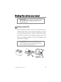
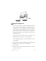
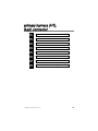
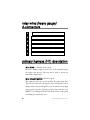
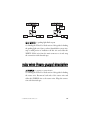
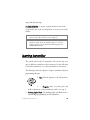
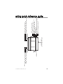
560T
➤Installation
Guide
NOTE:
This product is intended for installation by a professional installer only!
Any attempt to install this product by any person other than a trained professional
may result in severe damage to a vehicle’s electrical system and components.
© 2004 Directed Electronics, Inc. Vista, CA
N560T 08-04
www.directechs.com
DirectFax 800-999-1329 Technical Support 800-753-0800
These resources are for authorized Directed Dealer use only.
Code Hopping®, Doubleguard®, ESP®, FailSafe®, Ghost Switch®, Learn Routine™, NiteLite®, Nuisance Prevention® Circuitry, NPC™, Silent Mode™, Soft Chirp®,Valet®, and
Warn Away® are all Trademarks or Registered Trademarks of Directed Electronics, Inc.
table of contents
what is included . . . . . . . . . . . . . . . . . . . . . . . . . . . . . . . . . . . . . . . . . . . . . . . . . . . . . . 1
warning! safety first . . . . . . . . . . . . . . . . . . . . . . . . . . . . . . . . . . . . . . . . . . . . . . . . . . . 1
installation points to remember . . . . . . . . . . . . . . . . . . . . . . . . . . . . . . . . . . . . . . . . . . 4
before the installation . . . . . . . . . . . . . . . . . . . . . . . . . . . . . . . . . . . . . . . . . . . . . 4
after the installation . . . . . . . . . . . . . . . . . . . . . . . . . . . . . . . . . . . . . . . . . . . . . . 4
finding the wires you need . . . . . . . . . . . . . . . . . . . . . . . . . . . . . . . . . . . . . . . . . . . . . . 5
obtaining constant 12V. . . . . . . . . . . . . . . . . . . . . . . . . . . . . . . . . . . . . . . . . . . . 5
finding the starter wire . . . . . . . . . . . . . . . . . . . . . . . . . . . . . . . . . . . . . . . . . . . . 6
finding the 12V switched wire . . . . . . . . . . . . . . . . . . . . . . . . . . . . . . . . . . . . . . 7
finding the accessory wire . . . . . . . . . . . . . . . . . . . . . . . . . . . . . . . . . . . . . . . . . . 8
finding the parking light wire . . . . . . . . . . . . . . . . . . . . . . . . . . . . . . . . . . . . . . . 8
finding the tachometer wire . . . . . . . . . . . . . . . . . . . . . . . . . . . . . . . . . . . . . . . . 9
factory anti-theft systems (immobilizers) . . . . . . . . . . . . . . . . . . . . . . . . . . . . . . . . . . 10
primary harness (H1),8-pin connector . . . . . . . . . . . . . . . . . . . . . . . . . . . . . . . . . . . . 11
relay wires (heavy gauge) 6-connectors . . . . . . . . . . . . . . . . . . . . . . . . . . . . . . . . . . . . 12
primary harness (H1) description . . . . . . . . . . . . . . . . . . . . . . . . . . . . . . . . . . . . . . . . 12
relay wires (heavy guage) description . . . . . . . . . . . . . . . . . . . . . . . . . . . . . . . . . . . . . 17
learning transmitter . . . . . . . . . . . . . . . . . . . . . . . . . . . . . . . . . . . . . . . . . . . . . . . . . . 19
testing the system . . . . . . . . . . . . . . . . . . . . . . . . . . . . . . . . . . . . . . . . . . . . . . . . . . . . 20
control module programming . . . . . . . . . . . . . . . . . . . . . . . . . . . . . . . . . . . . . . . . . . 21
troubleshooting . . . . . . . . . . . . . . . . . . . . . . . . . . . . . . . . . . . . . . . . . . . . . . . . . . . . . 22
glossary of terms . . . . . . . . . . . . . . . . . . . . . . . . . . . . . . . . . . . . . . . . . . . . . . . . . . . . 24
wiring quick reference guide . . . . . . . . . . . . . . . . . . . . . . . . . . . . . . . . . . . . . . . . . . . 25
notes . . . . . . . . . . . . . . . . . . . . . . . . . . . . . . . . . . . . . . . . . . . . . . . . . . . . . . . . . . . . . 27 z
© 2004 Directed Electronics, Inc.
i
ii
© 2004 Directed Electronics, Inc.
what is included
➤
➤
➤
➤
➤
➤
Control module
One 2-button transmitter
Hood pinswitch
Toggle override switch
8-pin main H1 harness
Heavy guage relay wires (6)
warning! safety first
warning! This system is intended for automatic, fuel-injected vehicles only. Installation
in any other vehicle is contrary to its intended use.
warning! On vehicles with air bags or supplemental restraint systems (SRS) you may
notice a bright yellow tube with small wires
in it marked SRS underneath the steering
column near the key cylinder. DO NOT
tamper or unplug these for any reason to
prevent costly damages to the vehicle or
personal injury. Tampering may cause
unintended deployment of airbags.
warning! Verify that the vehicle is set to
park and that the parking brake is set
before beginning installation.
© 2004 Directed Electronics, Inc.
1
The following safety warnings must be observed at all times:
➤
➤
➤
2
Due to the complexity of this system, installation of this
product must only be performed by an authorized Directed
Electronics dealer.
When properly installed, this system can start the vehicle via
a command signal from the remote control transmitter.
Therefore, never operate the system in an area that does not
have adequate ventilation. The following precautions are the
sole responsibility of the user; however, authorized Directed
Electronics dealers should make the following recommendations to all users of this system:
1. Never operate the system in an enclosed or partially
enclosed area without ventilation (such as a garage).
2. When parking in an enclosed or partially enclosed area
or when having the vehicle serviced, the remote start
system must be disabled using the installed toggle
switch.
3. It is the user's sole responsibility to properly handle and
keep out of reach from children all remote control transmitters to assure that the system does not unintentionally remote start the vehicle.
4. THE USER MUST INSTALL A CARBON
MONOXIDE DETECTOR IN OR ABOUT THE
LIVING AREA ADJACENT TO THE VEHICLE.
ALL DOORS LEADING FROM ADJACENT
LIVING AREAS TO THE ENCLOSED OR
PARTIALLY ENCLOSED VEHICLE STORAGE
AREA MUST AT ALL TIMES REMAIN CLOSED.
Use of this product in a manner contrary to its intended
mode of operation may result in property damage, personal
injury, or death. Except when performing the Safety Check
© 2004 Directed Electronics, Inc.
➤
outlined in this installation guide, (1) Never remotely start
the vehicle with the vehicle in gear, and (2) Never remotely
start the vehicle with the keys in the ignition. The user will
be responsible for having the neutral safety feature of the
vehicle periodically checked, wherein the vehicle must not
remotely start while the car is in gear. This testing should be
performed by an authorized Directed Electronics dealer in
accordance with the Safety Check outlined in this product
installation guide. If the vehicle starts in gear, cease remote
start operation immediately and consult with the user to fix
the problem immediately.
After the remote start module has been installed, test the
remote start module in accordance with the Safety Check
outlined in this installation guide. If the vehicle starts when
performing the Neutral Safety Shutdown Circuit test, the
remote start unit has not been properly installed. The remote
start module must be removed or properly reinstalled so that
the vehicle does not start in gear. All installations must be
performed by an authorized Directed Electronics dealer.
OPERATION OF THE REMOTE START MODULE IF
THE VEHICLE STARTS IN GEAR IS CONTRARY TO
ITS INTENDED MODE OF OPERATION. OPER ATING THE REMOTE START SYSTEM UNDER
THESE CONDITIONS MAY RESULT IN PROPERTY
DAMAGE OR PERSONAL INJURY. IMMEDIATELY
CEASE THE USE OF THE UNIT AND REPAIR OR
DISCONNECT THE INSTALLED REMOTE START
MODULE. DIRECTED ELECTRONICS, INC. WILL
NOT BE HELD RESPONSIBLE OR PAY FOR INSTALLATION OR REINSTALLATION COSTS.
© 2004 Directed Electronics, Inc.
3
installation points to remember
➜ before the installation
➤
Please read this entire installation guide before beginning the
installation. The installation of this remote start system
requires interfacing with many of the vehicle’s systems. Many
new vehicles use low-voltage or multiplexed systems that can
be damaged by low-resistance testing devices, such as test
lights and logic probes (computer safe test lights). Test all
circuits with a high-quality digital multi-meter before
making connections.
➤
Do not disconnect the battery if the vehicle has an anti-theftcoded radio. If equipped with an air bag, avoid disconnecting
the battery if possible. Many airbag systems will display a
diagnostic code through their warning lights after they lose
power. Disconnecting the battery requires this code to be
erased, which can require a trip to the dealer.
➤
Remove the domelight fuse. This prevents accidentally
draining the battery.
➤
Roll down a window to avoid being locked out of the car.
➜ after the installation
➤
Test all functions. The "Using Your System" section of the
Owner's Guide is very helpful when testing.
➤
Complete the vehicle Safety Check outlined in this manual
prior to the vehicle reassembly.
4
© 2004 Directed Electronics, Inc.
finding the wires you need
IMPORTANT! Do not use a 12V test light or logic
probe (computer safe test light) to locate these wires!
All testing described in this manual assumes the use of
a digital multimeter.
➜ obtaining constant 12V
We recommend two possible sources for 12V constant: The (+)
terminal of the battery, or the constant 12V supply to the ignition switch. Always install a fuse within 12 inches of this connection. If the fuse will also be powering other circuits, such as door
locks, a power window module, or a Nite-Lite® headlight control
system, fuse accordingly.
IMPORTANT! Do not remove the fuse holder on the
red wire. It ensures that the control module has its own
fuse, of the proper value, regardless of how many accessories are added to the main power feed.
© 2004 Directed Electronics, Inc.
5
➜ finding the starter wire
The starter wire provides 12V directly to the starter or to a relay
controlling starter. In some vehicles, it is necessary to power a
cold start circuit. A cold start circuit will test exactly like a starter
circuit, but it does not control the starter. Instead, the cold start
circuit is used to prime the fuel injection system for starting when
the vehicle is cold.
Use the following procedure to find the starter wire with your
multimeter:
1. Set to DCV or DC voltage (12V or 20V is fine).
2. Attach the (-) probe of the meter to chassis ground.
3. Probe the wire you suspect of being the starter wire. The
steering column is an excellent place to find this wire.
Remember you do not need to
interrupt the starter at the same
point you test it. Hiding the
control module and connections is
always recommended.
4. Turn the ignition key switch to the start position. Make sure
the car is not in gear! If your meter reads (+)12V, go to the
next step. If it doesn’t, probe another wire.
5. Cut the wire you suspect of being the starter wire.
6. Attempt to start the car. If the starter engages, reconnect it
and go back to Step 3. If the starter does not turn over, you
have the right wire.
6
© 2004 Directed Electronics, Inc.
➜ finding the 12V switched wire
The ignition wire is powered when the key is in the run or start
position. This is because the ignition wire powers the ignition
system (spark plugs, coil) as well as the fuel delivery system (fuel
pump, fuel injection computer). Accessory wires lose power
when the key is in the start position to make more current available to the starter motor.
Use the following procedure to find the (+)12V ignition wire
with your multimeter:
1. Set to DCV or DC voltage (12V or 20V is fine).
2. Attach the (-) probe of the meter to chassis ground.
3.
Probe the wire you suspect of being
the ignition wire. The steering
column harness or ignition switch
harness is an excellent place to find
this wire.
4. Turn the ignition key switch to the run position. If your
meter reads (+)12V, go to the next step. If it does not read
(+)12V, probe another wire.
5. Now turn the key to the start position. The meter display
should stay steady, not dropping by more than a few tenths
of a volt. If it drops close to or all the way to zero, go back to
Step 3. If it stays steady at (+)12V, you have found an ignition wire.
© 2004 Directed Electronics, Inc.
7
➜ finding the accessory wire
An accessory wire will show (+)12V when the key is in the accessory and run positions. It will not show (+)12V during the
cranking cycle. There will often be more than one accessory wire
in the ignition harness. The correct accessory wire will power the
vehicle's climate control system. Some vehicles may have separate wires for the blower motor and the air conditioning
compressor. In such cases, it will be necessary to add a relay to
power the second accessory wire.
➜ finding the parking light wire
There are several different types of parking light circuits. The
following description is for a standard negative-triggered parking
light circuit, usually located at the light switch. If the web vehicle
information suggests a different type of parking light circuit,
please contact Directed Technical Support.
Using the web information on the vehicle, locate the suspected
wire and place the red lead of the meter to a constant (+)12 volt
source and secure it. Place the multi-meter in the DC position.
Probe the suspected wire. With the switch in the off position the
meter will read off. While watching the meter, turn the switch to
the parking light position. The meter should read 12V. While
testing the suspected wire, run the dash dimmer light control up
and down — the voltage should NOT vary. If the voltage does
vary, continue probing to find the correct wire.
8
© 2004 Directed Electronics, Inc.
➜ finding the tachometer wire
To test for a tachometer wire, a multimeter capable of testing AC
voltage must be used. The tachometer wire will show between
1V and 6V AC. In multi-coil ignition systems, the system can
learn individual coil wires. Individual coil wires in a multi-coil
ignition system will register lower amounts of AC voltage. Also,
if necessary, the system can use a fuel injector control wire for
engine speed sensing.
Common locations for a tachometer wire are the ignition coil,
instrument cluster, fuel injectors, or engine computers.
Use the following procedure to locate the tachometer wire with
your multimeter.
1. Set the multimeter to ACV or AC voltage and a range of 12V or 20V.
2. Attach the (-) probe of the meter to chassis ground.
3. Start the engine.
4. Probe the wire you suspect of being the tachometer wire with the
red probe of the meter.
© 2004 Directed Electronics, Inc.
9
5. If this is the correct wire the meter will read between 1 and 6
VAC and the voltage will vary as the engine rpm is changed.
factory anti-theft systems
(immobilizers)
Vehicle anti-theft systems (immobilizers) require installation of a
bypass module. The bypass module allows for easy interfacing,
while still maintaining the OEM security system’s integrity. For
vehicle listings and required bypass, see DirectFax Document
1059, available only to authorized dealers though the technical
resources listed at the front of this guide.
10
© 2004 Directed Electronics, Inc.
primary harness (H1),
8-pin connector
H1/1
— BLUE
H1/2
— VIOLET/WHITE
H1/3
— BROWN
H1/4
— GRAY
H1/5
— BLACK
H1/6
— WHITE/BLUE
H1/7
— LT. GREEN/BLACK
H1/8
— WHITE
© 2004 Directed Electronics, Inc.
(-) 200mA Status Output
Tachometer Input
(+) Brake Switch Shutdown Input
(-) Hood Pin Shutdown Input
Ground
(-) Remote Start Activation Input
Factory Alarm Disarm
(-) Parking Light Flash Output
11
relay wires (heavy gauge)
6-connectors
A
— PURPLE
B
— RED
C
— ORANGE
D
— PINK
E
— RED
F
— PINK/WHITE
(+) Output to Starter Circuit
(+) 12V Input 30A Fused
(+) Output to Accessory Circuit
(+) Output to Ignition Circuit
(+) 12V Input 30A Fused
(+) Output to Ign2/Acc2 Circuit
primary harness (H1) description
H1/1 BLUE (-) 200 mA status output
Provides a 200mA output as soon as the control module begins
the remote start process. This wire can be used to activate an
immobilizer bypass unit.
H1/2 VIOLET/WHITE tachometer input
This input provides the control module the engine rpm data.
This wire is connected to the negative side of the ignition coil in
vehicles with conventional ignition coils. In multi-coil and high
energy ignition systems, locating a proper signal may be more
difficult. (See Finding the Wires You Need section of this guide
for finding the tachometer wire.)
12
© 2004 Directed Electronics, Inc.
H1/3 BROWN (+) brake switch shutdown input
This wire must be connected to the vehicle’s brake light wire.
This is the wire that shows (+) 12V when the brake pedal is
depressed. The remote start will be disabled or shut down any
time the brake pedal is pressed.
Locate the factory brake wire using your meter. Find the switch
at the top of the metal arm coming off the brake pedal. There are
usually two wires connected to that switch. Locate the wire color
according to the web information. With your black meter lead
still in the kick panel, probe the suspected wire with the meter.
With the brake pedal at rest the meter should read zero. While
watching the tester, depress the brake pedal. The meter should
read 12V. Once you have located the correct brake wire, strip a
small portion of insulation off this wire and solder the small
BROWN (H1/3) wire on the main harness to it and wrap the
connection with electrical tape.
important! Do not use the vehicle until you confirm the
operation of the brake shutdown.
H1/4 GRAY (-) hood pin shutdown input
This wire must be connected to the hood pinswitch. This input
will disable or shut down the remote start when the hood is
opened.
© 2004 Directed Electronics, Inc.
13
Installing the hood pin switch requires drilling a ¼-inch hole in the
metal lip under the hood. Choose a location that will allow the pin
switch to be depressed when the hood is closed. The pin switch has
a spade connector on the bottom for the wire connection.
Place the wire with the spade connector onto the pin switch and
run the wire into the vehicle’s passenger compartment through a
factory rubber grommet. Using a sharp, pointed object poke a
hole into the grommet and attach the wire to the object with
electrical tape. Pull the wire through the grommet taking extra
care to keep the wire away from any moving parts or anything
that will generate extreme heat. Once the wire is run into the
vehicle and secured from any moving parts, solder the wire to
the GRAY (H1/4) wire on the main wire connector and wrap
the connection with electrical tape.
important! Do not use the vehicle until you confirm the
operation of the hood pin shutdown.
The bypass toggle switch is designed to bypass the remote start
in an emergency or to disable the remote start functions
14
© 2004 Directed Electronics, Inc.
temporarily (i.e., for service on the vehicle or when parking in an
enclosed area). This switch is to be mounted in an easily accessible location in the passenger compartment.
Connect the toggle switch as shown below.
HOOD PIN SWITCH OPEN WHEN HOOD IS CLOSED
TO GRAY (H1/5) WIRE
ON
CONTROL MODULE
HOOD PIN SWITCH CONNECTOR
BYPASS
TOGGLE
SWITCH
BYPASSED WHEN CLOSED
H1/5 BLACK ground
Remove any paint and connect this wire to bare metal, preferably with a factory bolt rather than your own screw. (Screws tend
to either strip or loosen with time.) We recommend grounding
all your components to the same point in the vehicle.
note: More problems are attributed to poor ground connections than any other cause. Take extra care to ensure
the ground is a clean metal-to-metal contact and secure.
© 2004 Directed Electronics, Inc.
15
SELF-TAPPING
BOLT OR SCREW
GROUND
WIRE
DIA-591
NOTE: REMOVE ANY PAINT
BELOW RING CONNECTOR
RING
TERMINAL
H1/6 WHITE/BLUE (-) remote start activation input
Two pulses on this wire within 3-seconds will initiate the start,
or two pulses within 3-seconds will cancel the start. This input
can be wired to a push button switch located in the passenger
compartment or it can be used for diagnostic troubleshooting.
H1/7 LT. GREEN/BLACK factory alarm disarm
This wire sends a negative pulse every time the remote start is
activated. This can be used to pulse the disarm wire of the
vehicle’s factory anti-theft device. Use a relay to send a (-) or (+)
pulse to the disarm factory wire as shown in the following
diagrams.
note: In most instances the negative pulse output can be
connected directly to the factory disarm wire. The circuit
shown on the left below is provided for those instances
where direct connection will not correctly function.
16
© 2004 Directed Electronics, Inc.
H1/8 WHITE (-) parking light flash output
See Finding the Wires You Need section of this guide for finding
the parking light wire. Once you have identified the correct wire,
strip a small portion of insulation off this wire and solder the
WHITE (H1/8) wire from the main connector to it and wrap
the connection with electrical tape.
relay wires (heavy guage) description
A–PURPLE (+) output to starter circuit
See Finding the Wires You Need section of this guide for finding
the starter wire. Reconnect both ends of the starter wire and
solder this PURPLE wire to the starter wires. Wrap the connection with electrical tape.
© 2004 Directed Electronics, Inc.
17
B, E–RED (+) 12V inputs 30A fused
warning! Before making any connection
to constant battery power make sure that
the two green 30 amp fuses are removed
from the fuse holders on the two thick red
wires. Failure to do so may cause fire or
shorting of sensitive electrical components.
See Finding the Wires You Need section of this guide for finding
the 12V constant power wire. Solder the two RED wires from
the control module to the 12V constant power wire and cover
the connection with electrical tape.
note: If the vehicle has two separate (+)12V feeds to the
ignition switch, connect one RED wire from the control
module to each of the vehicle’s (+)12V feeds.
C–ORANGE (+) output to accessory circuit
See Finding the Wires You Need section of this guide for finding
the accessory wire. Solder the ORANGE wire to the accessory
wire and wrap with electrical tape.
D–PINK (+) output to ignition circuit
See Finding the Wires You Need section of this guide for finding
the ignition wire. Solder the PINK wire to the ignition wire and
18
© 2004 Directed Electronics, Inc.
wrap with electrical tape.
F–PINK/WHITE (+) output to ignition2/accessory2 circuit
Connect this wire to the second ignition or accessory wire in the
vehicle.
note: For vehicles that do not have a second ignition or
accessory wire, this connection is not required.
note! The WHITE/BLUE (H1/6) wire, (-) remote start
activation input, from the primary harness is used for
testing purposes. Contact Directed Technical Support for
additional information.
learning transmitter
The system comes with one transmitter. The receiver can store
up to 4 different transmitter codes in memory. Use the following
to learn the transmitter or to add a transmitter to the system.
The following is the basic sequence of steps to remember whenever
programming this unit:
1. Key. Turn the ignition to the ON position.
2.
Program. After 5-seconds, press and
hold both buttons on the transmitter, until—(see step 3).
3. Parking Lights Flash. The parking lights will flash twice to
acknowledge programming of this transmitter.
© 2004 Directed Electronics, Inc.
19
To add a second transmitter (within 5-seconds of the first transmitter parking light flash learn acknowledgment):
1. Program. Hold the both buttons on the additional transmitter for an additional 5-seconds, until—(see step 2).
2. Parking Lights Flash. The parking lights will flash twice to
acknowledge programming of this transmitter.
testing the system
Once installation and transmitter learn have been completed,
the operation of the system can be tested.
Place the two 30-amp fuses back into the relay harness red wire
fuse holders. Make sure that the vehicle is in park with the emergency brake on and the hood closed. Press
once on the
remote control to initiate the remote start function. The parking
lights should flash to confirm the remote start command has
been received, The accessories and ignition should turn on
followed by the starter cranking and the vehicle engine running.
Pressing
on the remote will shut the engine off.
20
© 2004 Directed Electronics, Inc.
control module programming
Dependent on the vehicle, use the following data with the
instructions to program
PROGyour system. These wire loops are found
at the side of the control
ARM module.
DISARM
Diesel Mode (BLUE) - Cut this loop if you have a diesel vehicle.
When cut the remote start will start the engine about 30 seconds
after pressing the START button twice.
STOP
Uncut – Gas Mode
Cut – Diesel Mode
Voltage Mode/Tachometer Mode - Default is voltage mode. The
control module will automatically look at the tachometer input
during normal driving. If it finds a valid tachometer signal the
module will use tachometer mode, otherwise the module will use
voltage mode (battery voltage will rise after the engine starts).
To program tachometer mode, start the engine and let it run for
at least 30 seconds. If the tachometer is seen by the control
module, it will enter tachometer mode, and will monitor the
tachometer input for the next startup.
The system is programmed to attempt two starts using
tachometer mode. If after the second start attempt the control
module did not see a tachometer input the system will attempt
to start a third time using voltage mode.
© 2004 Directed Electronics, Inc.
21
troubleshooting
➤
The ignition comes on, but the starter will not crank.
Does it start with the key in the ignition? If so, does the
vehicle have an engine immobilizer?
Will it start with the brake pedal depressed? (Make sure to
disconnect the brake shutdown when performing this test.)
If so, it may have a brake/starter interlock.
Is the correct starter wire being energized? Check by energizing it yourself with a fused test lead.
➤
The starter cranks for 1 or 2-seconds but does not start.
Either the wrong ignition wire is being energized, the
system’s ignition and accessory wires have been connected
backwards, or the vehicle has two ignition circuits. Try activating the unit with the ignition key in the “run” position. If
the vehicle then runs normally, retest your ignition system.
➤
The starter continues to crank even though the engine has
started.
Has the tach wire been learned? See the Tach Learning
section of this guide.
Is the tach wire receiving the correct information? Either the
wrong tach wire has been used, or a bad connection exists.
➤
The climate control system does not work while the unit is
operating the vehicle.
Either the wrong accessory wire is being energized or more
22
© 2004 Directed Electronics, Inc.
than one ignition or accessory wire must be energized in
order to operate the climate control system.
➤
The remote start will not activate.
Check harnesses and connections. Make sure the harnesses
are fully plugged into the remote start module. Make sure
there are good connections to the vehicle wiring.
Check voltage and fuses. Use a meter and check for voltage
between the RED wire and the BLACK ground wire. If you
have less than battery voltage, check the and both 30A fuses
on the relay satellite. Also make sure that the ground wire is
going to a good paint-free chassis ground.
➤
The remote start will activate but the starter never engages.
1. Check for voltage on the purple starter wire two seconds
after the remote start becomes active. If there is voltage
present, skip to Step 4. If there is no voltage present, advance
to Step 2.
2. Check the 30A fuses.
3. Make sure the purple starter wire is connected on the
starter side of the optional starter kill relay.
4. Does the vehicle have an immobilizer? Some immobilizer
systems will not allow the vehicle to crank if active.
5. Check connections. The two red heavy gauge input wires
should have solid connections. "T-taps", or "scotch locks"
are not recommended for any high current heavy gauge
wiring. Also, if the vehicle has more than one 12-volt input
wire, then connect one red wire to each.
© 2004 Directed Electronics, Inc.
23
➤
The vehicle starts, but immediately dies.
Does the vehicle have an immobilizer? The vehicle’s immobilizer will cut the fuel and/or spark during unauthorized
starting attempts.
➤
The vehicle will start and run only for about 10 seconds.
Is the remote start programmed for voltage sense? Try
programming the unit using a tach wire.
glossary of terms
Control Module: The “brain” of your system. Usually hidden
under the dash area of the vehicle. It houses the microprocessor
that monitors your vehicle and controls all system functions.
Transmitter: A hand-held, remote control which operates the
various functions of your system.
24
© 2004 Directed Electronics, Inc.
© 2004 Directed Electronics, Inc.
ANTENNA
ORANGE (+) 30A output to accessory circuit
RED (+) 30A high current 12V input
VIOLET (+) output to starter circuit
BLUE WIRE LOOP CUT FOR DIESEL VEHICLES
BLUE (-) 200 mA status output
VIOLET/WHITE tachometer input
BROWN (+) brake switch shutdown input
GRAY (-) hood pin shutdown input
BLACK ground
WHITE/BLUE (-) remote start activation input
LIGHT GREEN/BLACK factory alarm disarm
WHITE (-) parking light flash output
PINK (+) output to ignition circuit
RED (+) 30A high current 12V input
PINK/WHITE (+) output to ignition/ACC2 circuit
wiring quick reference guide
25
26
© 2004 Directed Electronics, Inc.
notes
_________________________________________________
_________________________________________________
_________________________________________________
_________________________________________________
_________________________________________________
_________________________________________________
_________________________________________________
_________________________________________________
_________________________________________________
_________________________________________________
_________________________________________________
_________________________________________________
_________________________________________________
_________________________________________________
_________________________________________________
_________________________________________________
_________________________________________________
_________________________________________________
_________________________________________________
_________________________________________________
_________________________________________________
© 2004 Directed Electronics, Inc.
27