1
LS 6000 Series
About This Manual
Table of Contents
Index
Copyright
Feedback
Product Reference Guide
70-33186-01
Revision B
January 1999
LS 6000 Series
Product Reference Guide
70-33186-01
Revision B
January 1999
1998 - 1999 by Symbol Technologies, Inc. All rights reserved.
No part of this publication may be reproduced or used in any form, or by
any electrical or mechanical means, without permission in writing from
Symbol. This includes electronic or mechanical means, such as
photocopying, recording, or information storage and retrieval systems.
The material in this manual is subject to change without notice.
The software is provided strictly on an “as is” basis. All software,
including firmware, furnished to the user is on a licensed basis. Symbol
grants to the user a non-transferable and non-exclusive license to use each
software or firmware program delivered hereunder (licensed program).
Except as noted below, such license may not be assigned, sublicensed, or
otherwise transferred by the user without prior written consent of
Symbol. No right to copy a licensed program in whole or in part is
granted, except as permitted under copyright law. The user shall not
modify, merge, or incorporate any form or portion of a licensed program
with other program material, create a derivative work from a licensed
program, or use a licensed program in a network without written
permission from Symbol. The user agrees to maintain Symbol’s copyright
notice on the licensed programs delivered hereunder, and to include the
same on any authorized copies it makes, in whole or in part. The user
agrees not to decompile, disassemble, decode, or reverse engineer any
licensed program delivered to the user or any portion thereof.
Symbol reserves the right to make changes to any software or product to
improve reliability, function, or design.
Symbol does not assume any product liability arising out of, or in
connection with, the application or use of any product, circuit, or
application described herein.
No license is granted, either expressly or by implication, estoppel, or
otherwise under any Symbol Technologies, Inc., intellectual property
rights. An implied license only exists for equipment, circuits, and
subsystems contained in Symbol products.
Symbol, Spectrum One, and Spectrum24 are registered trademarks of
Symbol Technologies, Inc. Other product names mentioned in this manual
may be trademarks or registered trademarks of their respective companies
and are hereby acknowledged.
Symbol Technologies, Inc.
One Symbol Plaza
Holtsville, New York 11742-1300
http://www.symbol.com
Contents
About This Manual
Chapter Descriptions . . . . . . . . . . . . . . . . . . . . . . . . . . . . . . ix
Notational Conventions . . . . . . . . . . . . . . . . . . . . . . . . . . . . .x
Related Publications . . . . . . . . . . . . . . . . . . . . . . . . . . . . . . .x
Service Information . . . . . . . . . . . . . . . . . . . . . . . . . . . . . . . xi
Symbol Support Center . . . . . . . . . . . . . . . . . . . . . . . . .xii
Warranty . . . . . . . . . . . . . . . . . . . . . . . . . . . . . . . . . . . . . . .xii
Chapter 1. Introduction
Overview . . . . . . . . . . . . . . . . . . . . . . . . . . . . . . . . . . . . . . 1-1
Using Your Scanner . . . . . . . . . . . . . . . . . . . . . . . . . . . . . . 1-2
Chapter 2. Setup
Unpacking . . . . . . . . . . . . . . . . . . . . . . . . . . . . . . . . . . . . . 2-1
Installing the Scanner Cable . . . . . . . . . . . . . . . . . . . . . . . . 2-1
Switching Cables . . . . . . . . . . . . . . . . . . . . . . . . . . . . 2-2
Electronic Article Surveillance (EAS) (Optional) . . . . . . . . 2-3
Connecting to a Host . . . . . . . . . . . . . . . . . . . . . . . . . . . . . 2-3
iii
LS 6000 Series Product Reference Guide
Chapter 3. Scanning With the LS 6000
Scanning In Hand-Held Mode . . . . . . . . . . . . . . . . . . . . . . 3-1
Scanning in Hands-Free Mode . . . . . . . . . . . . . . . . . . . . . . 3-3
Selecting Beeper Volume . . . . . . . . . . . . . . . . . . . . . . . . . . 3-4
Beeper Indications . . . . . . . . . . . . . . . . . . . . . . . . . . . . . . . 3-5
LED Indications . . . . . . . . . . . . . . . . . . . . . . . . . . . . . . . . . 3-6
Chapter 4. Maintenance and Specifications
Maintaining Your Scanner . . . . . . . . . . . . . . . . . . . . . . . . . 4-1
Scan Zone . . . . . . . . . . . . . . . . . . . . . . . . . . . . . . . . . . . . . 4-2
Technical Specifications . . . . . . . . . . . . . . . . . . . . . . . . . . . 4-3
What If... . . . . . . . . . . . . . . . . . . . . . . . . . . . . . . . . . . . . . . 4-5
Chapter 5. Programming the LS 6000
Operational Parameters . . . . . . . . . . . . . . . . . . . . . . . . . . . 5-1
Defaults . . . . . . . . . . . . . . . . . . . . . . . . . . . . . . . . . . . 5-2
Set Default Parameter . . . . . . . . . . . . . . . . . . . . . . . . . . . . 5-7
Host Type . . . . . . . . . . . . . . . . . . . . . . . . . . . . . . . . . . . . . 5-8
IBM 46XX Host Types . . . . . . . . . . . . . . . . . . . . . . . . 5-8
RS-232C Host Types . . . . . . . . . . . . . . . . . . . . . . . . 5-10
Trigger Mode . . . . . . . . . . . . . . . . . . . . . . . . . . . . . . . . . . 5-16
Time to Return to Continuous Omnidirectional . . . . . . . 5-18
Beeper Volume . . . . . . . . . . . . . . . . . . . . . . . . . . . . . . . . . 5-19
Beeper Frequency . . . . . . . . . . . . . . . . . . . . . . . . . . . . . . . 5-21
Time-out Between Decodes, Same Symbol . . . . . . . . . . . . 5-23
Time-out Between Decodes, Different Symbols . . . . . . . . 5-24
Laser On Time . . . . . . . . . . . . . . . . . . . . . . . . . . . . . . . . . 5-25
Rest Mode Time-out 5-26
Beep After Good Decode . . . . . . . . . . . . . . . . . . . . . . . . . 5-28
Linear Code Type Security Level . . . . . . . . . . . . . . . . . . . 5-29
iv
Contents
UPC/EAN Options . . . . . . . . . . . . . . . . . . . . . . . . . . . . . . 5-32
Enable/Disable UPC-E . . . . . . . . . . . . . . . . . . . . . . . 5-32
Enable/Disable UPC-A . . . . . . . . . . . . . . . . . . . . . . . 5-33
Enable/Disable EAN-8 . . . . . . . . . . . . . . . . . . . . . . . 5-34
Enable/Disable EAN-13 . . . . . . . . . . . . . . . . . . . . . . 5-35
Enable/Disable Bookland EAN . . . . . . . . . . . . . . . . . 5-36
Decode UPC/EAN Supplementals . . . . . . . . . . . . . . . 5-37
Decode UPC/EAN Supplemental Redundancy . . . . . 5-39
Transmit UPC-A Check Digit . . . . . . . . . . . . . . . . . . 5-40
Transmit UPC-E Check Digit . . . . . . . . . . . . . . . . . . 5-41
Random Weight Check Digit . . . . . . . . . . . . . . . . . . 5-42
UPC-A Preamble . . . . . . . . . . . . . . . . . . . . . . . . . . . . 5-43
UPC-E Preamble . . . . . . . . . . . . . . . . . . . . . . . . . . . . 5-45
Convert UPC-E to UPC-A . . . . . . . . . . . . . . . . . . . . . 5-47
EAN Zero Extend . . . . . . . . . . . . . . . . . . . . . . . . . . . 5-48
UPC/EAN Predecode Block . . . . . . . . . . . . . . . . . . . 5-49
UPC/EAN Security Level . . . . . . . . . . . . . . . . . . . . . 5-51
Linear UPC/EAN Decode . . . . . . . . . . . . . . . . . . . . . 5-54
Linear Supplemental Decode . . . . . . . . . . . . . . . . . . 5-55
UPC/EAN Decode Performance . . . . . . . . . . . . . . . . 5-56
UPC/EAN Coupon Code . . . . . . . . . . . . . . . . . . . . . 5-58
Code 128 Options . . . . . . . . . . . . . . . . . . . . . . . . . . . . . . 5-59
Enable/Disable Code 128 . . . . . . . . . . . . . . . . . . . . . 5-59
Code 128 Decode Performance . . . . . . . . . . . . . . . . . 5-60
Enable/Disable UCC/EAN-128 . . . . . . . . . . . . . . . . . 5-62
Code 39 Options . . . . . . . . . . . . . . . . . . . . . . . . . . . . . . . 5-63
Enable/Disable Code 39 . . . . . . . . . . . . . . . . . . . . . . 5-63
Set Lengths for Code 39 . . . . . . . . . . . . . . . . . . . . . . 5-64
Code 39 Check Digit Verification . . . . . . . . . . . . . . . 5-67
Transmit Code 39 Check Digit . . . . . . . . . . . . . . . . . 5-68
Code 39 Decode Performance . . . . . . . . . . . . . . . . . . 5-69
Enable/Disable Code 39 Full ASCII . . . . . . . . . . . . . 5-71
v
LS 6000 Series Product Reference Guide
Interleaved 2 of 5 Options . . . . . . . . . . . . . . . . . . . . . . . . 5-73
Enable/Disable Interleaved 2 of 5 . . . . . . . . . . . . . . . 5-73
Set Lengths for Interleaved 2 of 5 . . . . . . . . . . . . . . . 5-74
I 2 of 5 Check Digit Verification . . . . . . . . . . . . . . . . 5-77
Transmit I 2 of 5 Check Digit . . . . . . . . . . . . . . . . . . 5-79
Convert I 2 of 5 to EAN-13 . . . . . . . . . . . . . . . . . . . 5-80
Codabar Options . . . . . . . . . . . . . . . . . . . . . . . . . . . . . . . 5-81
Enable/Disable Codabar . . . . . . . . . . . . . . . . . . . . . . 5-81
Set Lengths for Codabar . . . . . . . . . . . . . . . . . . . . . . 5-82
CLSI Editing . . . . . . . . . . . . . . . . . . . . . . . . . . . . . . . 5-85
NOTIS Editing . . . . . . . . . . . . . . . . . . . . . . . . . . . . . 5-86
Transmit Code ID Character . . . . . . . . . . . . . . . . . . . . . . 5-87
Pause Duration . . . . . . . . . . . . . . . . . . . . . . . . . . . . . . . . 5-89
Prefix/Suffix Values . . . . . . . . . . . . . . . . . . . . . . . . . . . . . 5-90
Scan Data Transmission Format . . . . . . . . . . . . . . . . . . . 5-91
RS-232C Parameters . . . . . . . . . . . . . . . . . . . . . . . . . . . . 5-95
Baud Rate . . . . . . . . . . . . . . . . . . . . . . . . . . . . . . . . . 5-95
Parity . . . . . . . . . . . . . . . . . . . . . . . . . . . . . . . . . . . . 5-99
Check Receive Errors . . . . . . . . . . . . . . . . . . . . . . . 5-102
Hardware Handshaking . . . . . . . . . . . . . . . . . . . . . 5-103
Software Handshaking . . . . . . . . . . . . . . . . . . . . . . 5-107
Host Serial Response Timeout . . . . . . . . . . . . . . . . 5-111
RTS Line State . . . . . . . . . . . . . . . . . . . . . . . . . . . . 5-112
Stop Bit Select . . . . . . . . . . . . . . . . . . . . . . . . . . . . . 5-113
ASCII Format . . . . . . . . . . . . . . . . . . . . . . . . . . . . . 5-114
Beep on <BEL> . . . . . . . . . . . . . . . . . . . . . . . . . . . . 5-115
Intercharacter Delay . . . . . . . . . . . . . . . . . . . . . . . . 5-116
Numeric Bar Codes . . . . . . . . . . . . . . . . . . . . . . . . . . . . 5-117
Cancel . . . . . . . . . . . . . . . . . . . . . . . . . . . . . . . . . . . 5-122
vi
Contents
Appendix A. Programming Reference
UCC/EAN-128 . . . . . . . . . . . . . . . . . . . . . . . . . . . . . . . . . A-1
AIM Code Identifiers . . . . . . . . . . . . . . . . . . . . . . . . . . . . . A-4
Modifier Characters . . . . . . . . . . . . . . . . . . . . . . . . . . A-5
ASCII Character Set . . . . . . . . . . . . . . . . . . . . . . . . . . . . . . A-8
vii
LS 6000 Series Product Reference Guide
viii
About This Guide
The LS 6000 Series Product Reference Guide provides general
information about connection and operation of the LS 6000
scanner series.
Chapter Descriptions
Following are brief descriptions of each chapter in this guide.
!
!
!
!
!
!
Chapter 1, Introduction provides a product overview
and a brief description on using the scanner.
Chapter 2, Setup provides information on connecting
the scanner to the host.
Chapter 3, Scanning With the LS 6000 describes how
to use the scanner and defines operator feedback.
Chapter 4, Maintenance and Specifications includes
tips on properly maintaining your scanner, and
technical specifications of the scanner.
Chapter 5, Programming the LS 6000 provides all the
bar codes necessary to program your scanner.
Appendix A, Programming Reference contains useful
reference material such as ASCII tables and AIM code
identifiers.
ix
LS 6000 Series Product Reference Guide
Notational Conventions
The following conventions are used in this document:
!
!
!
The term “LS 6000” applies to the LS 6000, LS 6004,
and LS 6005, except where specifically noted.
Bullets (•) indicate:
" action items
" lists of alternatives
" lists of required steps that are not necessarily
sequential
Sequential lists (e.g., those that describe step-by-step
procedures) appear as numbered lists.
Related Publications
The following is a list of documents that you may find useful if
you want to know more about the LS 6000 Scanner.
!
!
x
LS 6000 Series Quick Reference Guide
p/n 70-33187-XX
Symbol Omnidirectional Scanner Advanced
Programmer’s Guide
p/n 70-15600-XX
About This Guide
Service Information
If you have a problem with your equipment, contact the Symbol
Support Center. Before calling, have the model number and
serial number at hand.
Call the Support Center from a phone near the equipment so
that the service person can try to talk you through your
problem. If the equipment is found to be working properly and
the problem is symbol readability, the Support Center will
request samples of your bar codes for analysis at our plant.
If your problem cannot be solved over the phone, you may need
to return your equipment for servicing. If that is necessary, you
will be given specific directions.
Note: Symbol Technologies is not
responsible for any damages incurred
during shipment if the approved
shipping container is not used.
Shipping the units improperly can
possibly void the warranty. If the
original shipping container was not
kept, contact Symbol to have another
sent to you.
xi
LS 6000 Series Product Reference Guide
Symbol Support Center
For service information, warranty information or technical
assistance contact or call the Symbol Support Center in:
United States
Canada
Symbol Technologies, Inc.
One Symbol Plaza
Holtsville, New York 11742-1300
1-800-653-5350
Symbol Technologies Canada, Inc.
2540 Matheson Boulevard East
Mississauga, Ontario, Canada
L4W 422
(905) 629-7226
Europe, Latin America, Africa
Asia/Pacific
Symbol Technologies International
Symbol Place
Winnersh Triangle, Berkshire
RG41 5TP
United Kingdom
0800 3282424(Inside UK)
+44 118 945 7529 (Outside UK)
Symbol Technologies Asia, Inc.
230 Victoria Street #04-05
Bugis Junction Office Tower
Singapore 188024
337-6588 (Inside Singapore)
+65-337-6588 (Outside Singapore)
If you purchased your Symbol product from a Symbol Business
Partner, contact that Business Partner for service.
Warranty
Symbol Technologies, Inc (“Symbol”) manufactures its hardware products in
accordance with industry-standard practices. Symbol warrants that for a period of
twelve (12) months from date of shipment, products will be free from defects in
materials and workmanship.
This warranty is provided to the original owner only and is not transferable to any
third party. It shall not apply to any product (i) which has been repaired or altered
unless done or approved by Symbol, (ii) which has not been maintained in
accordance with any operating or handling instructions supplied by Symbol, (iii)
which has been subjected to unusual physical or electrical stress, misuse, abuse,
power shortage, negligence or accident or (iv) which has been used other than in
accordance with the product operating and handling instructions. Preventive
maintenance is the responsibility of customer and is not covered under this
warranty.
xii
About This Guide
Wear items and accessories having s Symbol serial number, will carry a 90-day
limited warranty. Non-serialized items will carry a 30-day limited warranty.
Warranty Coverage and Procedure
During the warranty period, Symbol will repair or replace defective products
returned to Symbol’s manufacturing plan in the US. For warranty service in North
America, call the Symbol Support Center at 1-800-653-5350. International
customers should contact the local Symbol office or support center. If warranty
service is required, Symbol will issue a Return Material Authorization Number.
Products must be shipped in the original or comparable packaging, shipping and
insurance charges prepaid. Symbol will ship the repaired or replacement product
freight and insurance prepaid in North America. Shipments from the US or other
locations will be made F.O.B. Symbol’s manufacturing plant.
Symbol will use new or refurbished parts at its discretion and will own all parts
removed from repaired products. Customer will pay for the replacement product
in case it does not return the replaced product to Symbol within 3 days of receipt
of the replacement product. The process for return and customer’s charges will be
in accordance with Symbol’s Exchange Policy in effect at the time of the exchange.
Customer accepts full responsibility for its software and data including the
appropriate backup thereof.
Repair or replacement of a product during warranty will not extend the original
warranty term.
Symbol’s Customer Service organization offers an array of service plans, such as
on-site, depot, or phone support, that can be implemented to meet customer’s
special operational requirements and are available at a substantial discount during
warranty period.
General
Except for the warranties stated above, Symbol disclaims all warranties, express
or implied, on products furnished hereunder, including without limitation implied
warranties of merchantability and fitness for a particular purpose. The stated
express warranties are in lieu of all obligations or liabilities on part of Symbol for
damages, including without limitation, special, indirect, or consequential damages
arising out of or in connection with the use or performance of the product.
Seller’s liability for damages to buyer or others resulting from the use of any
product, shall in no way exceed the purchase price of said product, except in
instances of injury to persons or property.
Some states (or jurisdictions) do not allow the exclusion or limitation of incidental
or consequential damages, so the proceeding exclusion or limitation may not apply
to you.
xiii
LS 6000 Series Product Reference Guide
xiv
Chapter 1
Introduction
Overview
Symbol Technologies’ LS 6000 scanner combines the benefits of
omni-directional scanning with a light-weight, hand-held
design. The scanner converts easily to hands-free use with an
optional presentation stand.
The LS 6000 successfully reads most code symbologies,
densities, and colors, produced by a wide range of printing
techniques.
The LS 6000 scanner supports the following interfaces:
!
!
LS 6004-I000 (RS-232C) - This scanner contains onboard discrete RS-232C communications for connecting
to RS-232C asynchronous terminals and host systems. It
also accommodates any of the Synapse™ “Smart
Cables” which allows you to connect to a wide variety
of host systems.
LS 6004-I090 (RS-232C with EAS) - This variation of
the LS 6004 also supports Checkpoint Electronic Article
Surveillance (EAS) modes V and VII.
1-1
LS 6000 Series Product Reference Guide
!
!
LS 6005-I000 (IBM 468X/469X) - The LS 6005 is fully
compatible with the entire line of IBM 468X/469X
terminals. It also accommodates the full line of Synapse
Smart Cables.
LS 6005-I090 (IBM 468X/469X with EAS) - The LS
6005-I090 also provides additional signal lines for EAS
deactivation (Checkpoint modes V and VII).
Using Your Scanner
If the scanner is powered by the host, ensure the host is
connected to a power outlet. When power is applied to the host,
the scanner powers up.
If the scanner is powered by an external power supply, ensure
the power supply is connected to a power outlet. When the
power supply is connected to the scanner, the scanner powers
up.
The green LED on top of the scanner illuminates and 3 powerup beeps sound, indicating the scanner is operational.
The LS 6000’s LED and beeper indicate scanning activity. These
indications are described in LED Indications and Beeper
Indications on page 3-5.
If the scanner is inactive for more than a pre-programmed
length of time, it enters a low power “rest” mode to conserve
energy. When you need to scan again, just bring a bar code to
the scanner window to “wake up” the scanner.
1-2
Chapter 2
Setup
Unpacking
Remove the scanner from its packing and inspect it for damage.
If the scanner was damaged in transit, call the Symbol Support
Center at one of the telephone numbers listed on page xii. KEEP
THE PACKING. It is the approved shipping container and
should be used if you ever need to return your equipment for
servicing.
Installing the Scanner Cable
To connect the cable to the LS 6000 scanner:
1.
Switch off all devices connected to the LS 6000 cable.
2-1
LS 6000 Series Product Reference Guide
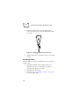
2.
Plug the modular connector on the cable into the
receptacle in the bottom of the LS 6000 handle. Listen
for a click.
Figure 2-1. Plugging Connector into Scanner
3.
Gently tug the cable to ensure the connector is properly
secured.
Switching Cables
Different cables are required for different hosts. To change the
scanner cable:
1.
2.
3.
2-2
Unplug the installed cable’s modular connector by
depressing the connector clip with a screwdriver or
paper clip (through the access hole).
Carefully slide out the cable.
Follow the steps for Installing the Scanner Cable above
to connect a new cable.
Setup
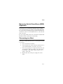
Electronic Article Surveillance (EAS)
(Optional)
Because there are several Checkpoint EAS systems available,
your local Checkpoint representative must install the EAS cable.
To contact your local Checkpoint representative inside the U.S.
call 800-257-5540, ext. 4300. Outside the U.S., call (609) 8481800, ext. 4300.
If you are using an EAS cable, refer to the Universal Cable EAS
Installation Sheet (Symbol p/n 70-32824-XX).
Connecting to a Host
Following are detailed instructions for connecting the LS 6000
to your host.
1.
2.
3.
4.
Power down the host terminal.
Connect the interface cable to the host terminal (refer to
your terminal manual to locate the correct port).
If necessary, plug the power supply into the power jack
on the interface cable. Depending on the cable, this is
located either on the cable’s connector itself, or on a
“lump” on the cable.
Plug the other end of the power supply into an AC
outlet.
2-3
LS 6000 Series Product Reference Guide
5.
Connect the other end of the interface cable to the
scanner.
Figure 2-2. Plugging Connector into Scanner
6.
Set the LS 6000 to communicate with your particular
POS terminal by scanning the appropriate bar code(s).
Depending on your terminal, these are located either in
Chapter 5, Programming the LS 6000, or the Synapse
Interface Guide.
7. Power up the host terminal. Ensure that the scanner
driver port is enabled by following the terminal
instructions.
8. Verify that the scanner is successfully reading bar codes
and transmitting their content to the host terminal.
See What If... on page 4-5 if you are having problems after
completing these steps.
2-4
Chapter 3
Scanning With the LS 6000
Scanning In Hand-Held Mode
The LS 6000 may be placed on the counter-top or in the Desk
Mount Stand (optional). The scanner operates in one of the
following three trigger modes, programmable by the bar codes
in Trigger Mode on page 5-16:
!
!
!
Triggered Omnidirectional Mode (Default)
An omnidirectional scan pattern activates upon trigger
pull.
Triggered Single Scan Line Mode
A single scan line appears upon trigger pull.
Combination Mode
The omnidirectional scan pattern is always on and ready
to decode. When the trigger is pulled, the scanner emits
a single scan line to decode, then reverts back to
omnidirectional constant-on. This mode is only for
hand-held use.
3-1
LS 6000 Series Product Reference Guide
To scan in hand-held mode, pick up the scanner and hold it
within the scanning range for the bar code. If the scanner is in
the constant-on mode, it decodes the bar code automatically. If
the scanner is in a triggered mode, pull the trigger to activate the
scan pattern and decode the bar code.
Figure 3-1. Holding the Scanner
3-2
Scanning With the LS 6000
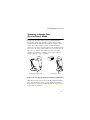
Scanning in Hands-Free
(Presentation) Mode
To place the LS 6000 scanner in the optional Hands-Free
Presentation Stand, slide the rubber “chin” support on the
scanner into the notch in the stand until the scanner is firmly
seated. The scanner emits a constant-on omnidirectional
pattern. To scan a bar code, bring the bar code anywhere within
10 in. (25.4 cm) of the scanner window for a successful decode.
Bar codes can either be directed in toward the nose of the
scanner (“presentation” scanning) or from side to side in a
sweeping motion (“swipe” scanning).
Inserting LS 6000 into Stand
Scanning in the Stand
Figure 3-2. Inserting the Scanner into Stand and Scanning
When the LS 6000 is removed from the Presentation Stand, the
laser shuts off and the scanner operates in the programmed
trigger mode (see Scanning In Hand-Held Mode on page 3-1 for
trigger mode descriptions).
3-3
LS 6000 Series Product Reference Guide
Selecting Beeper Volume
The LS 6000 emits a short beep when it successfully reads a bar
code. There are three volume settings for this decode beep. To
change the setting, hold down the trigger for five seconds. The
scanner cycles through three settings, emitting a 2-beep tone at
each setting. To select a particular setting, release the trigger
after the desired 2-beep tone.
Note: Beeper volume can also be set by
scanning the programming bar codes
for Beeper Volume on page 5-19.
To adjust the frequency (tone) of the scanner’s beeper, see Beeper
Frequency on page 5-21.
3-4
Scanning With the LS 6000
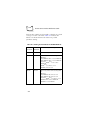
Beeper Indications
The beeper indicates the scanner’s status as follows:
Table 3-1. Beeper Indications
Beeper
Indication
3 Beeps
Power up (or reset) has occurred.
1 Beep
A bar code has been successfully decoded.
4 Beeps
A transmission error has occurred. Bar
code data was not received by the host.
Fast warble
A programming parameter was entered
successfully.
3-5
LS 6000 Series Product Reference Guide
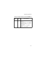
LED Indications
The green LED located on top of the scanner indicates the
operational status of the scanner. These LED indications are
defined below:
Table 3-2. LED Indications
LED
Indication
Off
No power is applied to the scanner.
On steady
The scanner is on and “ready to scan,”
or a flash download cable is attached.
Momentary flash off
A bar code has been successfully decoded.
Fast double-blinking
The scanner is in a programming sequence.
Fast sequential flashing
A scanner malfunction has occurred.
Slow steady blinking
The scanner is in flash program mode.
3-6
Chapter 4
Maintenance and Specifications
Maintaining Your Scanner
The only maintenance your LS 6000 scanner requires is an
occasional cleaning of the scan window to remove fingerprints
or other debris. Since the LS 6000 scan window is a high
performance optical element, care should be given during
cleaning.
Use only a mild soap and water solution applied to a soft, clean
cloth (NOT directly to the scan window). Buff the scan window
gently with the cloth to remove any streaking.
4-1
LS 6000 Series Product Reference Guide
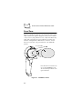
Scan Zone
When an omnidirectional mode is selected, the LS 6000 scanner
emits a 20-line scan pattern designed to allow you to read bar
codes, even very long and narrow ones, easily from almost any
angle. The scan pattern is projected directly out of the scan
window creating the three dimensional “scan zone” shown
below. To read a bar code, present the bar code within this
pattern.
10” (100% UPC)
Note: This scan zone is based on the
use of a 100% UPC/EAN bar code.
The zone will vary for different code
types and densities.
Figure 4-1. LS 6000 Scan Zone
4-2
Maintenance and Specifications
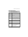
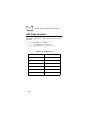
Technical Specifications
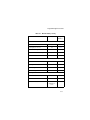
Table 4-1. Technical Specifications
ITEM
DESCRIPTION
Power
Requirements
5.2 VDC +/- 5% @400mA
Omnidirectional
Scan Pattern
20-line, 5-direction dynamic cross pattern; 1200
scans per second
Single-Line Scan
Pattern
60 scans per second
Decode Depth of
Field
Maximum working distance is
10 in. (25.4 cm) on 100% UPC/EAN symbol
Decode Capability
UPC/EAN/JAN (with and without
supplementals), Code 128, Code 39, Interleaved
2 of 5, Codabar, UCC/EAN 128, Bookland EAN
Durability
4 ft. (1.2 meter) drops to concrete
Operating
Temperature
32° to 104°F (0° to 40°C)
Storage
Temperature
-40° to 140°F (-40° to 60°C)
Humidity
5% to 95% non-condensing
Ambient Light
Immune to normal artificial indoor and natural
outdoor (direct sunlight) lighting conditions
Flourescent, incandescent, mercury vapor,
sodium vapor: 450 ft.-candles
Sunlight: 9000 ft.-candles
Weight
7.4 oz. (210 gm)
4-3
LS 6000 Series Product Reference Guide
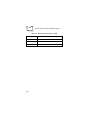
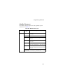
Table 4-1. Technical Specifications (cont’d)
ITEM
DESCRIPTION
Height
7.64 in. (194 mm)
Width
2.72 in. (69 mm)
Depth
3.19 in. (81 mm)
4-4
Maintenance and Specifications
What If...
Table 4-2. Troubleshooting
What if...
Then...
The scanner is not
decoding and the
green LED is not lit?
Refer to Chapter 2, Setup to verify that your
scanner is properly connected.
The scanner is not
decoding and the
green LED is lit?
Check the bar code to make sure it is not
defaced.
Verify that the code type you are scanning is
enabled.
Verify that the symbol length for that code type
is correct.
Try scanning similar bar codes of the same
code type.
Make sure the Beep After Good Decode
parameter is enabled.
Make sure a flash download cable is not being
used.
The scanner is not
transmitting to the
host terminal?
Make sure the scanner is connected to the
terminal.
Make sure the host terminal is properly
configured.
Be sure that you've scanned the proper host
type.
If you’re using RS-232, be sure all RS-232
parameters (e.g., baud rate, data bits,
handshaking) are set properly to communicate
with the host.
4-5
LS 6000 Series Product Reference Guide
4-6
Chapter 5
Programming the LS 6000
Operational Parameters
The LS 6000 is shipped with the settings shown in the Table 51 beginning on page 5-2. These default values are stored in nonvolatile memory and are preserved even when the scanner is
powered down. You can change these default values by
scanning the appropriate bar codes included in this manual.
These new values replace the standard default values in
memory. The default parameter values can be recalled by
scanning the SET ALL DEFAULTS bar code on page 5-7.
If you are using a Synapse cable, your host is autodetected, so
no host bar codes need to be scanned. If not, you must select a
terminal type even if the default parameters suit your needs. The
scanner automatically identifies the host type on power-up. It
makes this determination provided the host is powered-up
before the scanner is attached to it. You must then select the
appropriate terminal type for that host. For example, if the
scanner is connected to an IBM 4683, after you hear the powerup beeps, select the proper port from the choices in IBM 46XX
Host Types on page 5-8.
5-1
LS 6000 Series Product Reference Guide
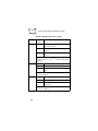
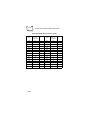
Defaults
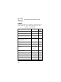
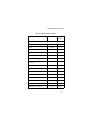
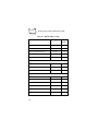
The following table lists the defaults for all parameters. If you
wish to change any option, scan the appropriate bar code(s).
Table 5-1. Default Table
Parameter
Default
Page
Number
Set Default Parameter
All Defaults
5-7
Host Type
See page 5-8
5-8
Triggered
Omnidirectional
5-16
0.5 seconds
5-18
High
5-19
Beeper Frequency
High Frequency
5-21
Time-out Between Decodes, Same
Symbol
Triggered: 200
msec; ConstantOn: 2 sec
5-23
600 msec
5-24
Laser On Time
2.0 seconds
5-25
Rest Mode Timeout
30 minutes
5-26
Enable
5-28
2
5-29
Trigger Mode
Time to Return to Continuous
Omnidirectional
Beeper Volume
Time-out Between Decodes,
Different Symbols
Beep After Good Decode
Linear Code Type Security Levels
5-2
Programming the LS 6000
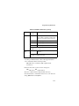
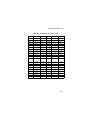
Table 5-1. Default Table (cont’d)
Parameter
Default
Page
Number
UPC-A
Enable
5-32
UPC-E
Enable
5-32
EAN-8
Enable
5-34
EAN-13
Enable
5-34
Bookland EAN
Disable
5-36
Decode UPC/EAN Supplementals
Ignore
5-37
Decode UPC/EAN Supplemental
Redundancy
20
5-39
Transmit UPC-A Check Digit
Enable
5-40
Transmit UPC-E Check Digit
Enable
5-41
Random Weight Check Digit
Disable
5-42
UPC-A Preamble
System Character
5-43
UPC-E Preamble
System Character
5-45
Convert UPC-E to A
Disable
5-47
EAN-8 Zero Extend
Disable
5-48
UPC/EAN Predecode Block
Reject
5-49
UPC/EAN
5-3
LS 6000 Series Product Reference Guide
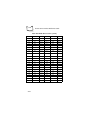
Table 5-1. Default Table (cont’d)
Parameter
Default
Page
Number
UPC/EAN Security Levels
0
5-51
Linear UPC/EAN Decode
Disable
5-54
Linear Supplemental Decode
Disable
5-55
Enable, Level 3
5-56
Disable
5-58
Enable
5-59
Enable, Level 3
5-60
Enable
5-62
Code 39
Enable
5-63
Set Length(s) for Code 39
1 to 55
5-64
Code 39 Check Digit Verification
Disable
5-67
Transmit Code 39 Check Digit
Disable
5-68
Code 39 Decode Performance
Enable, Level 3
5-69
Disable
5-71
UPC/EAN Decode Performance
UPC/EAN Coupon Code
Code 128
Code 128
Code 128 Decode Performance
UCC/EAN-128
Code 39
Code 39 Full ASCII Conversion
5-4
Programming the LS 6000
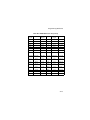
Table 5-1. Default Table (cont’d)
Parameter
Default
Page
Number
Disable
5-73
14
5-74
I 2 of 5 Check Digit Verification
Disable
5-77
Transmit I 2 of 5 Check Digit
Disable
5-79
Convert I 2 of 5 to EAN 13
Disable
5-80
Disable
5-81
5-55
5-82
CLSI Editing
Disable
5-85
NOTIS Editing
Disable
5-86
None
5-87
0
5-89
7013
(<CR/LF> for
serial)
5-90
Interleaved 2 of 5
Interleaved 2 of 5
Set Length(s) for I 2 of 5
Codabar
Codabar
Set Lengths for Codabar
Data Options
Transmit Code ID Character
Pause Duration
Prefix/Suffix Values
5-5
LS 6000 Series Product Reference Guide
Table 5-1. Default Table (cont’d)
Parameter
Default
Page
Number
Data as is
5-91
Standard
5-10
Baud Rate
9600
5-95
Parity
Even
5-99
Check Receive Errors
Check
5-102
Hardware Handshaking
None
5-103
Software Handshaking
None
5-107
Host Serial Response Time-out
2 Sec.
5-111
RTS Line State
Low
5-112
Stop Bit Select
1
5-113
ASCII Format
8-Bit
5-114
Disable
5-115
0
5-116
Scan Data Transmission Format
RS-232C
RS-232 Host Type
Beep on <BEL>
Intercharacter Delay
Numeric Bar Codes
5-6
5-117
Programming the LS 6000
Set Default Parameter
Scanning this bar code returns all parameters to the default
values listed in Table 5-1 beginning on page 5-2.
SET ALL DEFAULTS
5-7
LS 6000 Series Product Reference Guide
Host Type
If you’re using a Synapse cable, your host is autodetected, so no
host bar codes need to be scanned. If not, select an IBM 46XX
or RS-232 host from the following bar code menus.
IBM 46XX Host Types
To select one of the following as a POS Interface, scan the
appropriate bar code below.
Note: To properly communicate with 468X/
9X terminals, the driver
corresponding to the port being used
must be loaded and enabled when you
are configuring your terminal system.
See your terminal’s operating manual
for details.
Port 5B
5-8
Programming the LS 6000
Host Type (Cont’d)
Port 9B
Port 17/9E
5-9
LS 6000 Series Product Reference Guide
Host Type (Cont’d)
RS-232C Host Types
Three RS-232C hosts are set up with their own parameter
default settings (Table 5-2). Selecting the ICL, Fujitsu, or
Nixdorf RS-232C terminal sets the defaults listed below. These
defaults take precedence over standard defaults. So if you select
Fujitsu RS-232C, then select the standard defaults, the Fujitsu
defaults still take precedence.
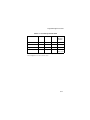
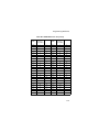
Table 5-2. Terminal Specific RS-232C
Parameter
Standard
ICL
FUJITSU
NIXDORF
Mode A/
Mode B
Transmit Code ID
No
Yes
Yes
Yes
Data Transmission
Format
Data as is
Data/
Suffix
Data/
Suffix
Data/Suffix
Suffix
CR/LF
(7013)
CR (1013) CR (1013)
CR (1013)
Baud Rate
9600
9600
9600
9600
Parity
Even
Even
None
Odd
Hardware
Handshaking
None
RTS/CTS
Option 3
None
RTS/CTS
Option 3
Software
Handshaking
None
None
None
None
Serial Response
Time-out
2 Sec.
9.9 Sec.
2 Sec.
9.9 Sec.
5-10
Programming the LS 6000
Table 5-2. Terminal Specific RS-232C
Parameter
Standard
ICL
FUJITSU
NIXDORF
Mode A/
Mode B
Stop Bit Select
One
One
One
One
ASCII Format
8-Bit
8-Bit
8-Bit
8-Bit
Disabled
Disabled
Disabled
Disabled
Low
High
Low
*Low = No
data to send
Beep On <BEL>
RTS Line State
*In the Nixdorf Mode B, if CTS is Low, scanning is disabled. When
CTS is High, the user can scan bar codes.
5-11
LS 6000 Series Product Reference Guide
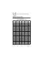
RS-232C Host Types (Cont’d)
Selecting the ICL, Fujitsu, or Nixdorf RS-232C terminal enables
the transmission of Code ID Characters as listed in Table 5-3,
below. These Code ID Characters are not programmable and
are separate from the Transmit Code ID feature. The Transmit
Code ID feature should not be enabled for these terminals.
Table 5-3. Terminal Specific Code ID Characters
ICL
FUJITSU
NIXDORF
UPC-A
“A”
“A”
“A”
UPC-E
“E”
“E”
“C0”
EAN-8
“FF”
“FF”
“B”
EAN-13
“F”
“F”
“A”
Code 39
“C” <len>
None
“M”
Codabar
“N” <len>
None
“N”
Code 128
“L” <len>
None
“K”
I 2 of 5
“I” <len>
None
“I”
UCC/EAN 128
“L” <len>
None
“P”
Bookland EAN
“F”
“F”
“A”
5-12
Programming the LS 6000
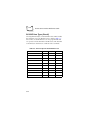
RS-232C Host Types (Cont’d)
To select an RS-232C Host Interface, scan one of the following
bar codes.
STANDARD RS-232C
ICL RS-232C
5-13
LS 6000 Series Product Reference Guide
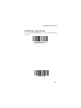
RS-232C Host Types (Cont’d)
NIXDORF RS-232C Mode A
NIXDORF RS-232C Mode B
5-14
Programming the LS 6000
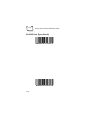
RS-232C Host Types (Cont’d)
FUJITSU RS-232C
5-15
LS 6000 Series Product Reference Guide
Trigger Mode
Scan a bar code below to select one of the following trigger
modes:
!
!
!
In Triggered Omnidirectional Mode, an omnidirectional
scan pattern activates upon trigger pull.
In Triggered Single Scan Line Mode, a single scan line
appears upon trigger pull.
If Combination Mode is selected, the omnidirectional
scan pattern is always on and ready to decode. When the
trigger is pulled, the scanner emits a single scan line to
decode, then reverts back to omnidirectional constanton. This mode is only for hand-held use.
TRIGGERED OMNIDIRECTIONAL MODE
5-16
Programming the LS 6000
Trigger Mode (Cont’d)
TRIGGERED SINGLE SCAN LINE MODE
COMBINATION MODE
(CONSTANT-ON OMNIDIRECTIONAL/
TRIGGERED SINGLE SCAN LINE)
5-17
LS 6000 Series Product Reference Guide
Time to Return to Continuous
Omnidirectional
This parameter sets the time the scanner issues a single scan line
on trigger pull before returning to the constant-on
omnidirectional pattern. It is programmable in 0.1 second
increments from 0.0 to 9.9 seconds. If this value is set to 0, the
trigger mode will not return to constant-on omnidirectional
automatically. In this case, pull the trigger twice quickly to
return to the constant-on omnidirectional pattern.
To set this time, scan the bar code. Next scan two numeric bar
codes beginning on page 5-117, the first representing seconds,
the second tenths of seconds. If you make an error, or wish to
change your selection, scan CANCEL on page 5-122.
TIME TO RETURN TO CONTINUOUS OMNI
5-18
Programming the LS 6000
Beeper Volume
To select a decode beep volume, scan the LOW VOLUME,
MEDIUM VOLUME, or HIGH VOLUME bar code.
Note: Beeper volume can also be set
manually using the instructions for
Selecting Beeper Volume on page 3-4.
LOW VOLUME
5-19
LS 6000 Series Product Reference Guide
Beeper Volume (Cont’d)
MEDIUM VOLUME
HIGH VOLUME
5-20
Programming the LS 6000
Beeper Frequency
To select a decode beep frequency (tone), scan the LOW
FREQUENCY, MEDIUM FREQUENCY, or HIGH
FREQUENCY bar code.
LOW FREQUENCY
5-21
LS 6000 Series Product Reference Guide
Beeper Frequency (Cont’d)
MEDIUM FREQUENCY
HIGH FREQUENCY
5-22
Programming the LS 6000
Time-out Between Decodes, Same
Symbol
This parameter sets the minimum time between decodes of the
same symbol. It is programmable in 0.1 second increments from
0.0 to 9.9 seconds. (Setting this above 0.4 seconds is
recommended.)
Scan the bar code below to select a new time-out. Next scan two
numeric bar codes beginning on page 5-117, the first
representing seconds, the second tenths of seconds. If you make
an error, or wish to change your selection, scan CANCEL on
page 5-122.
TIME-OUT BETWEEN SAME SYMBOL
5-23
LS 6000 Series Product Reference Guide
Time-out Between Decodes,
Different Symbols
This parameter sets the minimum time between decodes of
different symbols. It is programmable in 0.1 second increments
from 0.0 to 9.9 seconds.
Scan the bar code below, then scan two numeric bar codes
beginning on page 5-117, the first representing seconds, the
second tenths of seconds. If you make an error, or wish to
change your selection, scan CANCEL on page 5-122.
TIME-OUT BETWEEN DIFFERENT SYMBOLS
5-24
Programming the LS 6000
Laser On Time
This parameter sets the maximum time decode processing
continues during a scan attempt. It is programmable in 0.1
second increments from 0.5 to 9.9 seconds.
To set a Laser On Time, scan the bar code below. Next scan two
numeric bar codes beginning on page 5-117 that correspond to
the desired time on. Single digit numbers must have a leading
zero. For example, to set a Time On of .5 seconds, scan the bar
code below, then scan the “0” and “5” bar codes. If you make
an error, or wish to change your selection, scan CANCEL on
page 5-122.
LASER ON TIME
5-25
LS 6000 Series Product Reference Guide
Rest Mode Time-out
This parameter sets the time the scanner remains active after any
scanning activity. Scan one of the four options. Depending on
the selection, the scanner enters a low power “rest” mode 15,
30, 60, or 90 minutes after the last attempted decode. The laser
blinks during this rest mode to conserve power. To awaken the
scanner, present the bar code you wish to scan to the scan
window.
15 MINUTES
30 MINUTES
5-26
Programming the LS 6000
Rest Mode Timeout (Cont’d)
60 MINUTES
90 MINUTES
5-27
LS 6000 Series Product Reference Guide
Beep After Good Decode
Scan a bar code below to select whether or not the unit beeps
after a good decode. If disabled, the beeper still operates during
parameter menu scanning and indicates error conditions.
BEEP AFTER GOOD DECODE
DO NOT BEEP AFTER GOOD DECODE
5-28
Programming the LS 6000
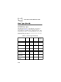
Linear Code Type Security Level
Note: Does not apply to Code 128.
The LS 6000 offers four levels of decode security for linear code
types (e.g., Code 39, Interleaved 2 of 5). Higher security levels
are selected for decreasing levels of bar code quality. As security
levels increase, the scanner’s aggressiveness decreases.
Select the security level appropriate for your bar code quality.
Linear Security Level 1
The following code types must be successfully read twice before
being decoded:
Code Type
Length
Codabar
All
I 2 of 5
8 or less
LINEAR SECURITY LEVEL 1
5-29
LS 6000 Series Product Reference Guide
Linear Security Level 2
The following code types must be successfully read twice before
being decoded:
Code Type
All
Length
All
LINEAR SECURITY LEVEL 2
Linear Security Level 3
Code types other than the following must be successfully read
twice before being decoded. The following codes must be read
three times:
Code Type
Length
I 2 of 5
8 or less
Codabar
8 or less
LINEAR SECURITY LEVEL 3
5-30
Programming the LS 6000
Linear Security Level 4
The following code types must be successfully read three times
before being decoded:
Code Type
All
Length
All
LINEAR SECURITY LEVEL 4
5-31
LS 6000 Series Product Reference Guide
UPC/EAN Options
Enable/Disable UPC-E
To enable or disable UPC-E, scan the appropriate bar code.
ENABLE UPC-E
DISABLE UPC-E
5-32
Programming the LS 6000
Enable/Disable UPC-A
To enable or disable UPC-A, scan the appropriate bar code.
ENABLE UPC-A
DISABLE UPC-A
5-33
LS 6000 Series Product Reference Guide
Enable/Disable EAN-8
To enable or disable EAN-8, scan the appropriate bar code
below.
ENABLE EAN-8
DISABLE EAN-8
5-34
Programming the LS 6000
Enable/Disable EAN-13
To enable or disable EAN-13, scan the appropriate bar code
below.
ENABLE EAN-13
DISABLE EAN-13
5-35
LS 6000 Series Product Reference Guide
Enable/Disable Bookland EAN
To enable or disable EAN Bookland, scan the appropriate bar
code below.
ENABLE BOOKLAND EAN
DISABLE BOOKLAND EAN
5-36
Programming the LS 6000
Decode UPC/EAN Supplementals
Supplementals are additionally appended characters (2 or 5)
according to specific code format conventions (e.g., UPC A+2,
UPC E+2, EAN 8+2). Three options are available.
!
!
!
If UPC/EAN with supplemental characters is selected,
UPC/EAN symbols without supplemental characters are
not decoded.
If UPC/EAN without supplemental characters is
selected, and the LS 6000 is presented with a UPC/
EAN plus supplemental symbol, the UPC/EAN is
decoded and the supplemental characters ignored.
An autodiscriminate option is also available. If this
option is selected, choose an appropriate Decode UPC/
EAN Supplemental Redundancy value from page 5-39.
A value of 5 or more is recommended.
Note: In order to minimize the risk of
invalid data transmission, it is
recommended that you select whether
to read or ignore supplemental
characters.
5-37
LS 6000 Series Product Reference Guide
Decode UPC/EAN Supplementals (Cont’d)
DECODE UPC/EAN WITH
SUPPLEMENTALS
IGNORE UPC/EAN WITH
SUPPLEMENTALS
AUTODISCRIMINATE UPC/
EAN SUPPLEMENTALS
5-38
Programming the LS 6000
Decode UPC/EAN Supplemental Redundancy
With Autodiscriminate UPC/EAN Supplementals selected, this
option adjusts the number of times a symbol without
supplementals is decoded before transmission. The range is
from two to twenty times. Five or above is recommended when
decoding a mix of UPC/EAN symbols with and without
supplementals, and the autodiscriminate option is selected.
Scan the bar code below to select a decode redundancy value.
Next scan two numeric bar codes beginning on page 5-117.
Single digit numbers must have a leading zero. If you make an
error, or wish to change your selection, scan CANCEL on page
5-122.
DECODE UPC/EAN
SUPPLEMENTAL REDUNDANCY
5-39
LS 6000 Series Product Reference Guide
Transmit UPC-A Check Digit
Scan the appropriate bar code below to transmit the symbol
with or without the UPC-A check digit.
TRANSMIT UPC-A
CHECK DIGIT
DO NOT TRANSMIT UPC-A
CHECK DIGIT
5-40
Programming the LS 6000
Transmit UPC-E Check Digit
Scan the appropriate bar code below to transmit the symbol
with or without the UPC-E check digit.
TRANSMIT UPC-E
CHECK DIGIT
DO NOT TRANSMIT UPC-E
CHECK DIGIT
5-41
LS 6000 Series Product Reference Guide
Random Weight Check Digit
A 4-digit or 5-digit random weight check digit may be
embedded in a UPC-A or EAN-13 bar code for additional price
verification. To enable either of these options, or disable the
option completely, scan the appropriate bar code below.
DISABLE RANDOM
WEIGHT CHECK DIGIT
ENABLE 4-DIGIT RANDOM
WEIGHT CHECK DIGIT
ENABLE 5-DIGIT RANDOM
WEIGHT CHECK DIGIT
5-42
Programming the LS 6000
UPC-A Preamble
Three options are given for lead-in characters for UPC-A
symbols transmitted to the host device: transmit system
character only, transmit system character and country code (“0”
for USA), and no preamble transmitted. The lead-in characters
are considered part of the symbol.
NO PREAMBLE
(<DATA>)
5-43
LS 6000 Series Product Reference Guide
UPC-A Preamble (Cont’d)
SYSTEM CHARACTER
(<SYSTEM CHARACTER> <DATA>)
SYSTEM CHARACTER & COUNTRY CODE
(< COUNTRY CODE> <SYSTEM CHARACTER>
<DATA>)
5-44
Programming the LS 6000
UPC-E Preamble
Three options are given for lead-in characters for UPC-E
symbols transmitted to the host device: transmit system
character only, transmit system character and country code (“0”
for USA), and no preamble transmitted. The lead-in characters
are considered part of the symbol.
NO PREAMBLE
(<DATA>)
5-45
LS 6000 Series Product Reference Guide
UPC-E Preamble (Cont’d)
SYSTEM CHARACTER
(<SYSTEM CHARACTER> <DATA>)
SYSTEM CHARACTER & COUNTRY CODE
(< COUNTRY CODE> <SYSTEM CHARACTER>
<DATA>)
5-46
Programming the LS 6000
Convert UPC-E to UPC-A
This parameter converts UPC-E (zero suppressed) decoded data
to UPC-A format before transmission. After conversion, data
follows UPC-A format and be affected by UPC-A programming
selections (e.g., Preamble, Check Digit).
Scanning DO NOT CONVERT UPC-E TO UPC-A allows you
to transmit UPC-E (zero suppressed) decoded data.
CONVERT UPC-E TO UPC-A
(ENABLE)
DO NOT CONVERT UPC-E TO UPC-A
(DISABLE)
5-47
LS 6000 Series Product Reference Guide
EAN Zero Extend
If this parameter is enabled, five leading zeros are added to
decoded EAN-8 symbols to make them compatible in format to
EAN-13 symbols.
Disabling this parameter returns EAN-8 symbols to their
normal format.
ENABLE EAN ZERO EXTEND
DISABLE EAN ZERO EXTEND
5-48
Programming the LS 6000
UPC/EAN Predecode Block
UPC/EAN bar codes are made up of two blocks representing
“left” and “right” halves. For example, bar code 1234567890
is divided into left block “12345”, and right block “67890”. To
maximize its aggressiveness, the LS 6000 can decode a UPC/
EAN symbol by “splicing” together a left block read by one
scan line, and a right block read by another.
Reject Predecode Block
This option provides additional protection (beyond the
embedded check digit) against mis-splicing a UPC/EAN block
from a symbol that has just been decoded (but has not
completely exited the scanner’s field of view), with a block from
a new symbol that has just been presented to the scanner. This
option requires the scanner to compare the new symbol against
the symbol just decoded to see if there are common blocks. If
either the left or right blocks match between symbols, the
scanner rejects the common block for the programmed Decode
Time-Off interval.
REJECT PREDECODE BLOCK
5-49
LS 6000 Series Product Reference Guide
Accept Predecode Block
This option allows immediate decode of a new UPC/EAN bar
code regardless of the previously decoded UPC/EAN bar code’s
block content.
ACCEPT PREDECODE BLOCK
5-50
Programming the LS 6000
UPC/EAN Security Level
The LS 6000 offers four levels of decode security for UPC/EAN
bar codes. Increasing levels of security are provided for
decreasing levels of bar code quality. There is an inverse
relationship between security and scanner aggressiveness, so be
sure to choose only that level of security necessary for any given
application.
UPC/EAN Security Level 0
This is the default setting which allows the scanner to operate in
its most aggressive state, while providing sufficient security in
decoding “in-spec” UPC/EAN bar codes.
UPC/EAN SECURITY LEVEL 0
5-51
LS 6000 Series Product Reference Guide
UPC/EAN Security Level 1
As bar code quality levels diminish, certain characters become
prone to misdecodes before others (i.e., 1, 2, 7, 8). If you are
experiencing mis-decodes of poorly printed bar codes, and the
mis-decodes are limited to these characters, select this security
level.
UPC/EAN SECURITY LEVEL 1
UPC/EAN Security Level 2
If you are experiencing misdecodes of poorly printed bar codes,
and the misdecodes are not limited to characters 1, 2, 7, and 8,
select this security level.
UPC/EAN SECURITY LEVEL 2
5-52
Programming the LS 6000
UPC/EAN Security Level 3
If you have tried Security Level 2, and are still experiencing
misdecodes, select this security level. Be advised, selecting this
option is an extreme measure against misdecoding severely out
of spec bar codes. Selection of this level of security significantly
impairs the decoding ability of the scanner. If this level of
security is necessary, you should try to improve the quality of
your bar codes.
UPC/EAN SECURITY LEVEL 3
5-53
LS 6000 Series Product Reference Guide
Linear UPC/EAN Decode
This option applies to code types containing two adjacent
blocks (e.g., UPC-A, EAN-8, EAN-13). When enabled, a bar
code is transmitted only when both the left and right blocks are
successfully decoded within one laser scan. This option should
be enabled when bar codes are in proximity to each other.
ENABLE LINEAR UPC/EAN DECODE
DISABLE LINEAR UPC/EAN DECODE
5-54
Programming the LS 6000
Linear Supplemental Decode
This option applies to code types containing two or five
character supplementals. When enabled, a bar code is
transmitted only when both the supplemental block and its
adjacent block are successfully decoded within one laser scan.
This option should be enabled when bar codes are in proximity
to each other.
ENABLE LINEAR SUPPLEMENTAL DECODE
DISABLE LINEAR SUPPLEMENTAL DECODE
5-55
LS 6000 Series Product Reference Guide
UPC/EAN Decode Performance
This option offers three levels of decode performance
(aggressiveness) for UPC/EAN symbols without supplementals.
Increasing the performance level reduces the amount of required
bar code orientation, which is useful if you are scanning very
long and/or truncated bar codes. Increased levels reduce decode
security.
If you enable this option, select a performance level from the
next page.
ENABLE UPC/EAN DECODE PERFORMANCE
DISABLE UPC/EAN DECODE PERFORMANCE
5-56
Programming the LS 6000
UPC/EAN Decode Performance (Cont’d)
If Decode Performance is enabled, select a level below.
UPC/EAN DECODE
PERFORMANCE LEVEL 1
UPC/EAN DECODE
PERFORMANCE LEVEL 2
UPC/EAN DECODE
PERFORMANCE LEVEL 3
5-57
LS 6000 Series Product Reference Guide
UPC/EAN Coupon Code
When enabled, this parameter decodes UPC-A, UPC-A with 2
supplemental characters, UPC-A with 5 supplemental
characters, and UPC-A/EAN 128 bar codes. Autodiscriminate
UPC/EAN With Supplemental Characters must be enabled.
ENABLE UPC/EAN COUPON CODE
DISABLE UPC/EAN COUPON CODE
5-58
Programming the LS 6000
Code 128 Options
Enable/Disable Code 128
To enable or disable Code 128, scan the appropriate bar code
below.
ENABLE CODE 128
DISABLE CODE 128
5-59
LS 6000 Series Product Reference Guide
Code 128 Decode Performance
This option offers three levels of decode performance
(aggressiveness) for Code 128 symbols. Increasing the
performance level reduces the amount of required bar code
orientation, which is useful if you are scanning very long and/or
truncated bar codes. Increased levels reduce decode security.
If you enable this option, you may select a decode performance
level from the next page.
ENABLE CODE 128 DECODE PERFORMANCE
DISABLE CODE 128 DECODE PERFORMANCE
5-60
Programming the LS 6000
Code 128 Decode Performance (Cont’d)
If Decode Performance is enabled, select a level below.
CODE 128 DECODE
PERFORMANCE LEVEL 1
CODE 128 DECODE
PERFORMANCE LEVEL 2
CODE 128 DECODE
PERFORMANCE LEVEL 3
5-61
LS 6000 Series Product Reference Guide
Enable/Disable UCC/EAN-128
To enable or disable UCC/EAN-128, scan the appropriate bar
code below. (See Appendix A for details on UCC/EAN-128.)
ENABLE UCC/EAN-128
DISABLE UCC/EAN-128
5-62
Programming the LS 6000
Code 39 Options
Enable/Disable Code 39
To enable or disable Code 39, scan the appropriate bar code
below.
ENABLE CODE 39
DISABLE CODE 39
5-63
LS 6000 Series Product Reference Guide
Set Lengths for Code 39
Lengths for Code 39 may be set for any length, one or two
discrete lengths, or lengths within a specific range. The length of
a code refers to the number of characters (i.e., human readable
characters), including check digit(s) the code contains. If Code
39 Full ASCII is enabled, Length Within a Range or Any Length
are the preferred options.
One Discrete Length
This option allows you to decode only those codes containing a
selected length. For example, if you select Code 39 One Discrete
Length, then scan 1, 4, only Code 39 symbols containing 14
characters are decoded. Numeric bar codes begin on page 5117. If you make an error or wish to change your selection,
scan CANCEL on page 5-122.
CODE 39 - ONE DISCRETE LENGTH
5-64
Programming the LS 6000
Two Discrete Lengths
This option allows you to decode only those codes containing
two selected lengths. For example, if you select Code 39 Two
Discrete Lengths, then scan 0, 2, 1, 4, only Code 39 symbols
containing 2 or 14 characters are decoded. Numeric bar
codes begin on page 5-117. If you make an error or wish to
change your selection, scan CANCEL on page 5-122.
CODE 39 - TWO DISCRETE LENGTHS
Length Within Range
This option allows you to decode a code type within a
specified range. For example, to decode Code 39 symbols
containing between 4 and 12 characters, first scan Code 39
Length Within Range. Then scan 0, 4, 1, and 2 (single digit
numbers must always be preceded by a leading zero). Numeric
bar codes begin on page 5-117. If you make an error or wish to
change your selection, scan CANCEL on page 5-122.
CODE 39 - LENGTH WITHIN RANGE
5-65
LS 6000 Series Product Reference Guide
Any Length
Scanning this option allows you to decode Code 39 symbols
containing any number of characters.
CODE 39 - ANY LENGTH
5-66
Programming the LS 6000
Code 39 Check Digit Verification
When enabled, this parameter checks the integrity of a Code 39
symbol to ensure it complies with specified algorithms.
Only those code 39 symbols which include a modulo 43 check
digit are decoded when this parameter is enabled.
ENABLE CODE 39 CHECK DIGIT
DISABLE CODE 39 CHECK DIGIT
5-67
LS 6000 Series Product Reference Guide
Transmit Code 39 Check Digit
Scan a bar code below to transmit the data with or without the
check digit.
TRANSMIT CODE 39 CHECK DIGIT
(ENABLE)
DO NOT TRANSMIT CODE 39 CHECK DIGIT
(DISABLE)
5-68
Programming the LS 6000
Code 39 Decode Performance
This option offers three levels of decode performance
(aggressiveness) for Code 39 symbols. Increasing the
performance level reduces the amount of required bar code
orientation, which is useful if you are scanning very long and/or
truncated bar codes. Increased levels reduce decode security.
If you enable this option, you may select a decode performance
level from the next page.
Note: This option only works with Code 39
One Discrete Length.
ENABLE CODE 39 DECODE PERFORMANCE
DISABLE CODE 39 DECODE PERFORMANCE
5-69
LS 6000 Series Product Reference Guide
Code 39 Decode Performance (Cont’d)
If Decode Performance is enabled, select a level below.
CODE 39 DECODE
PERFORMANCE LEVEL 1
CODE 39 DECODE
PERFORMANCE LEVEL 2
CODE 39 DECODE
PERFORMANCE LEVEL 3
5-70
Programming the LS 6000
Enable/Disable Code 39 Full ASCII
To enable or disable Code 39 Full ASCII, scan the appropriate
bar code below.
When enabled, the ASCII character set assigns a code to letters,
punctuation marks, numerals, and most control keystrokes on
the keyboard.
The first 32 codes are non-printable and are assigned to
keyboard control characters such as BACKSPACE and
RETURN. The other 96 are called printable codes because all
but SPACE and DELETE produce visible characters.
Code 39 Full ASCII interprets the bar code special character ($
+ % /) preceding a Code 39 character and assigns an ASCII
character value to the pair. For example, when Code 39 Full
ASCII is enabled and a +B is scanned, it is interpreted as b, %J
as ?, and $H emulates the keystroke BACKSPACE. Scanning
ABC$M outputs the keystroke equivalent of ABC ENTER.
Refer to Table A-4 in Appendix A.
The scanner does not autodiscriminate between Code 39 and
Code 39 Full ASCII.
5-71
LS 6000 Series Product Reference Guide
Enable/Disable Code 39 Full ASCII (Cont’d)
ENABLE CODE 39 FULL ASCII
DISABLE CODE 39 FULL ASCII
5-72
Programming the LS 6000
Interleaved 2 of 5 Options
Enable/Disable Interleaved 2 of 5
To enable or disable Interleaved 2 of 5, scan the appropriate bar
code below.
ENABLE INTERLEAVED 2 OF 5
DISABLE INTERLEAVED 2 OF 5
5-73
LS 6000 Series Product Reference Guide
Set Lengths for Interleaved 2 of 5
Lengths for I 2 of 5 may be set for any length, one or two
discrete lengths, or lengths within a specific range. The length of
a code refers to the number of characters (i.e., human readable
characters) the code contains, and includes check digits. Scan
the appropriate bar code to select one of the following options.
One Discrete Length
This option allows you to decode only those codes containing a
selected length. For example, if you select I 2 of 5 One Discrete
Length, then scan 1, 4, the only I 2 of 5 symbols decoded are
those containing 14 characters. Numeric bar codes begin on
page 5-117. If you make an error or wish to change your
selection, scan CANCEL on page 5-122.
I 2 of 5 - ONE DISCRETE LENGTH
5-74
Programming the LS 6000
Two Discrete Lengths
This option allows you to decode only those codes containing
two selected lengths. For example, if you select I 2 of 5 Two
Discrete Lengths, then scan 0, 2, 1, 4, the only I 2 of 5 symbols
decoded are those containing 2 or 14 characters. Numeric bar
codes begin on page 5-117. If you make an error or wish to
change your selection, scan CANCEL on page 5-122.
I 2 of 5 - TWO DISCRETE LENGTHS
Length Within Range
This option allows you to decode a code type within a specified
range. For example, to decode I 2 of 5 symbols containing
between 4 and 12 characters, first scan I 2 of 5 Length Within
Range. Then scan 0, 4, 1, and 2 (single digit numbers must
always be preceded by a leading zero). Numeric bar codes begin
on page 5-117. If you make an error or wish to change your
selection, scan CANCEL on page 5-122.
I 2 of 5 - LENGTH WITHIN RANGE
5-75
LS 6000 Series Product Reference Guide
Any Length
Scanning this option allows you to decode I 2 of 5 symbols
containing any number of characters.
Note: Selecting the Any Length option may
lead to misdecodes for I 2 of 5 codes.
I 2 of 5 - ANY LENGTH
5-76
Programming the LS 6000
I 2 of 5 Check Digit Verification
When enabled, this parameter checks the integrity of an I 2 of 5
symbol to ensure it complies a specified algorithm, either
Uniform Symbology Specification (USS), or Optical Product
Code Council (OPCC).
DISABLE
5-77
LS 6000 Series Product Reference Guide
I 2 of 5 Check Digit Verification (Cont’d)
USS CHECK DIGIT
OPCC CHECK DIGIT
5-78
Programming the LS 6000
Transmit I 2 of 5 Check Digit
Scan a bar code below to transmit the data with or without the
check digit.
TRANSMIT I 2 of 5 CHECK DIGIT
(ENABLE)
DO NOT TRANSMIT I 2 of 5 CHECK DIGIT
(DISABLE)
5-79
LS 6000 Series Product Reference Guide
Convert I 2 of 5 to EAN-13
This parameter converts a 14 character I 2 of 5 code into EAN13, and transmits to the host as EAN-13. In order to accomplish
this, the I 2 of 5 code must be enabled, one length must be set to
14, and the code must have a leading zero and a valid EAN-13
check digit.
CONVERT I 2 of 5 to EAN-13
(ENABLE)
DO NOT CONVERT I 2 of 5 to EAN-13
(DISABLE)
5-80
Programming the LS 6000
Codabar Options
Enable/Disable Codabar
To enable or disable Codabar, scan the appropriate bar code
below.
ENABLE CODABAR
DISABLE CODABAR
5-81
LS 6000 Series Product Reference Guide
Set Lengths for Codabar
Lengths for Codabar may be set for any length, one or two
discrete lengths, or lengths within a specific range. The length of
a code refers to the number of characters (i.e., human readable
characters) the code contains. It also includes any start or stop
characters. Scan the appropriate bar code to select one of the
following options.
One Discrete Length
This option allows you to decode only those codes containing a
selected length. For example, if you select Codabar One
Discrete Length, then scan 1, 4, the only Codabar symbols
decoded are those containing 14 characters. Numeric bar codes
begin on page 5-117. If you make an error or wish to change
your selection, scan CANCEL on page 5-122.
CODABAR - ONE DISCRETE LENGTH
5-82
Programming the LS 6000
Two Discrete Lengths
This option allows you to decode only those codes containing
two selected lengths. For example, if you select Codabar Two
Discrete Lengths, then scan 0, 2, 1, 4, the only Codabar symbols
decoded are those containing 2 or 14 characters. Numeric bar
codes begin on page 5-117. If you make an error or wish to
change your selection, scan CANCEL on page 5-122.
CODABAR - TWO DISCRETE LENGTHS
Length Within Range
This option allows you to decode a code type within a
specified range. For example, to decode Codabar symbols
containing between 4 and 12 characters, first scan Codabar
Length Within Range. Then scan 0, 4, 1, and 2 (single digit
numbers must always be preceded by a leading zero). Numeric
bar codes begin on page 5-117. If you make an error or wish to
change your selection, scan CANCEL on page 5-122.
CODABAR - LENGTH WITHIN RANGE
5-83
LS 6000 Series Product Reference Guide
Any Length
Scanning this option allows you to decode Codabar symbols
containing any number of characters.
CODABAR - ANY LENGTH
5-84
Programming the LS 6000
CLSI Editing
When enabled, this parameter strips the start and stop
characters and inserts a space after the first, fifth, and tenth
characters of a 14-character Codabar symbol.
Note: Symbol length does not include start
and stop characters.
ENABLE CLSI EDITING
DISABLE CLSI EDITING
5-85
LS 6000 Series Product Reference Guide
NOTIS Editing
When enabled, this parameter strips the start and stop
characters from decoded Codabar symbol.
ENABLE NOTIS EDITING
DISABLE NOTIS EDITING
5-86
Programming the LS 6000
Transmit Code ID Character
A code ID character identifies the code type of a scanned bar
code. This may be useful when the scanner is decoding more
than one code type. In addition to any single character prefix
already selected, the code ID character is inserted between the
prefix and the decoded symbol.
The user may select no code ID character, a Symbol Code ID
character, or an AIM Code ID character. The Symbol Code ID
characters are listed below; see AIM Code Identifiers in
Appendix A.
A = UPC-A, UPC-E, EAN-8, EAN-13
B = Code 39
C = Codabar
D = Code 128
F = Interleaved 2 of 5
K = UCC/EAN-128
L = Bookland EAN
SYMBOL CODE ID CHARACTER
5-87
LS 6000 Series Product Reference Guide
Transmit Code ID Character (Cont’d)
AIM CODE ID CHARACTER
NONE
5-88
Programming the LS 6000
Pause Duration
This parameter allows a pause to be inserted at any point in the
data transmission. Pauses are set by scanning a two-digit
number (i.e., two bar codes), and are measured in 1/10 second
intervals. For example, scanning bar codes “0” and “1” inserts
a 1/10 second pause; “0” and “5” gives you a 1/2 second delay.
Numeric bar codes begin on page 5-117. If you make an error
or wish to change your selection, scan DATA FORMAT
CANCEL on page 5-94.
PAUSE DURATION
5-89
LS 6000 Series Product Reference Guide
Prefix/Suffix Values
A prefix/suffix may be appended to scan data for use in data
editing. These values are set by scanning a four-digit number
(i.e., four bar codes) that corresponds to key codes for various
terminals. See Table A-4 in Appendix A for conversion
information. Numeric bar codes begin on page 5-117. If you
make an error or wish to change your selection, scan
CANCEL on page 5-122.
SCAN PREFIX
SCAN SUFFIX
5-90
Programming the LS 6000
Scan Data Transmission Format
To change the Scan Data Transmission Format, scan the SCAN
OPTIONS bar code below. Then select one of four options.
When you have made your selection, scan the ENTER bar code
on page 5-94. If you make a mistake, scan the DATA FORMAT
CANCEL bar code on page 5-94.
SCAN OPTIONS
5-91
LS 6000 Series Product Reference Guide
Scan Data Transmission Format
(Cont’d)
DATA AS IS
<DATA> <SUFFIX>
5-92
Programming the LS 6000
Scan Data Transmission Format
(Cont’d)
<PREFIX> <DATA>
<PREFIX> <DATA> <SUFFIX>
5-93
LS 6000 Series Product Reference Guide
Scan Data Transmission Format
(Cont’d)
ENTER
DATA FORMAT CANCEL
5-94
Programming the LS 6000
RS-232C Parameters
Baud Rate
Baud rate is the number of bits of data transmitted per second.
The scanner's baud rate setting should match the data rate
setting of the host device. If not, data may not reach the host
device or may reach it in distorted form.
BAUD RATE 300
5-95
LS 6000 Series Product Reference Guide
Baud Rate (Cont’d)
BAUD RATE 600
BAUD RATE 1200
5-96
Programming the LS 6000
Baud Rate (Cont’d)
BAUD RATE 2400
BAUD RATE 4800
5-97
LS 6000 Series Product Reference Guide
Baud Rate (Cont’d)
BAUD RATE 9600
BAUD RATE 19,200
5-98
Programming the LS 6000
Parity
A parity check bit is the most significant bit of each ASCII coded
character. Select the parity type according to host device
requirements.
Odd
If you select ODD parity, the parity bit has a value 0 or 1, based
on data, to ensure than an odd number of 1 bits are contained
in the coded character.
ODD
5-99
LS 6000 Series Product Reference Guide
Parity (Cont’d)
Even
If you select EVEN parity, the parity bit has a value 0 or 1, based
on data, to ensure than an even number of 1 bits are contained
in the coded character.
EVEN
Mark
Select MARK parity and the parity bit is always 1.
MARK
5-100
Programming the LS 6000
Parity (Cont’d)
Space
Select SPACE parity and the parity bit is always 0.
SPACE
None
Select None if no parity is desired.
NONE
5-101
LS 6000 Series Product Reference Guide
Check Receive Errors
Select whether or not the parity, framing, and overrun of
received characters are checked. The type of parity used is
selectable through the PARITY parameter.
CHECK FOR RECEIVED ERRORS
DO NOT CHECK FOR RECEIVED ERRORS
5-102
Programming the LS 6000
Hardware Handshaking
The data interface consists of an RS-232C port. The port has
been designed to operate either with or without the hardware
handshaking lines, Request to Send (RTS), and Clear to Send
(CTS).
If Standard RTS/CTS handshaking is selected, scan data is
transmitted according to the following sequence:
!
The controller reads the CTS line for activity. If CTS is
asserted, the controller waits up to 2 seconds for the host
to negate the CTS line. If, after 2 seconds (default), the
CTS line is still asserted, the scanner sounds a transmit
error and any scanned data is lost.
When the CTS line is negated, the controller asserts the
!
RTS line and waits up to 2 seconds for the host to assert
CTS. When the host asserts CTS, data is transmitted. If,
after 2 seconds (default), the CTS line is not asserted, the
scanner sounds a transmit error and discards the data.
When data transmission is complete, the controller
!
negates RTS 10 msec after sending the last character.
The host should respond by negating CTS. The
!
controller checks for a negated CTS upon the next
transmission of data.
During the transmission of data, the CTS line should be
asserted. If CTS is deasserted for more than 50 ms between
characters, the transmission is aborted, the scanner sounds a
transmission error, and the data is discarded.
If the above communications sequence fails, the scanner issues
an error indication. In this case, the data is lost and must be
rescanned.
5-103
LS 6000 Series Product Reference Guide
Hardware Handshaking (Cont’d)
If Hardware Handshaking and Software Handshaking are both
enabled, Hardware Handshaking takes precedence.
Note: The DTR signal is jumpered active.
Scan one of the following bar codes to select an option below.
No Hardware Handshaking
NONE
Standard RTS/CTS Hardware Handshaking
STANDARD RTS/CTS
5-104
Programming the LS 6000
Hardware Handshaking (Cont’d)
RTS/CTS Option 1
When RTS/CTS Option 1 is selected, the scanner asserts RTS
before transmitting and ignores the state of CTS. The scanner
deasserts RTS when the transmission is complete.
RTS/CTS OPTION 1
RTS/CTS Option 2
When Option 2 is selected, RTS is always high or low (userprogrammed logic level). However, the scanner waits for CTS to
be asserted before transmitting data. If CTS is not asserted
within 2 seconds (default), the scanner issues an error indication
and discards the data.
RTS/CTS OPTION 2
5-105
LS 6000 Series Product Reference Guide
Hardware Handshaking (Cont’d)
RTS/CTS Option 3
When Option 3 is selected, the scanner asserts RTS prior to any
data transmission, regardless of the state of CTS. The scanner
waits up to 2 seconds (default) for CTS to be asserted. If CTS is
not asserted during this time, the scanner issues an error
indication and discards the data. The scanner deasserts RTS
when transmission is complete.
RTS/CTS OPTION 3
5-106
Programming the LS 6000
Software Handshaking
This parameter offers control of the data transmission process
in addition to, or instead of, that offered by hardware
handshaking. There are five options.
If Software Handshaking and Hardware Handshaking are both
enabled, Hardware Handshaking takes precedence.
Scan the appropriate bar code to select one of the following
options.
None
When this option is selected, data is transmitted immediately.
NONE
5-107
LS 6000 Series Product Reference Guide
Software Handshaking (Cont’d)
ACK/NAK
When this option is selected, after transmitting data, the scanner
expects either an ACK or NAK response from the host.
Whenever a NAK is received, the scanner transmits the same
data again and waits for either an ACK or NAK. After three
unsuccessful attempts to send data when NAKs are received, the
scanner issues an error indication and discards the data.
The scanner waits up to the programmable Host Serial
Response Time-out to receive an ACK or NAK. If the scanner
does not get a response in this time, it issues an error indication
and discards the data. There are no retries when a time-out
occurs.
ACK/NAK
5-108
Programming the LS 6000
Software Handshaking (Cont’d)
ENQ
When this option is selected, the scanner waits for an ENQ
character from the host before transmitting data. If an ENQ is
not received within 2 seconds, the scanner issues an error
indication and discards the data. The host must transmit an
ENQ character at least every 2 seconds to prevent transmission
errors.
ENQ
ACK/NAK with ENQ
This combines the two previous options.
ACK/NAK with ENQ
5-109
LS 6000 Series Product Reference Guide
Software Handshaking (Cont’d)
XON/XOFF
An XOFF character turns the scanner transmission off until the
scanner receives an XON character. There are two situations for
XON/XOFF:
!
!
XOFF is received before the scanner has data to send.
When the scanner has data to send, it then waits for an
XON character before transmission. The scanner waits
up to 2 seconds to receive the XON. If the XON is not
received within this time, the scanner issues an error
indication and discards the data.
XOFF is received during a transmission. Data
transmission then stops after sending the current byte.
When the scanner receives an XON character, it sends
the rest of the data message. The scanner waits
indefinitely for the XON.
XON/XOFF
5-110
Programming the LS 6000
Host Serial Response Timeout
This parameter specifies how long the scanner waits for an
ACK, NAK, or CTS before determining that a transmission
error has occurred. This only applies when in one of the ACK/
NAK Software Handshaking modes, or RTS/CTS Hardware
Handshaking option.
The delay period can range from 0.0 to 9.9 seconds in .1-second
increments. After scanning the bar code below, scan two
numeric bar codes beginning on page 5-117. If you make an
error or wish to change your selection, scan CANCEL on
page 5-122.
HOST SERIAL RESPONSE TIME-OUT
5-111
LS 6000 Series Product Reference Guide
RTS Line State
This parameter is used to set the idle state of the Serial Host RTS
line. Scan a bar code below to select LOW RTS line state or
HIGH RTS line state.
HOST: LOW RTS
HOST: HIGH RTS
5-112
Programming the LS 6000
Stop Bit Select
The stop bit(s) at the end of each transmitted character marks
the end of transmission of one character and prepares the
receiving device for the next character in the serial data stream.
The number of stop bits selected (one or two) depends on the
number the receiving terminal is programmed to accommodate.
Set the number of stop bits to match host device requirements.
1 STOP BIT
2 STOP BITS
5-113
LS 6000 Series Product Reference Guide
ASCII Format
This parameter allows the scanner to interface with devices
requiring a 7-bit or 8-bit ASCII protocol.
7-BIT
8-BIT
5-114
Programming the LS 6000
Beep on <BEL>
When this parameter is enabled, the scanner issues a beep when
a <BEL> character is detected on the RS-232C serial line. <BEL>
is issued to gain a user's attention to indicate an illegal entry or
other important event.
BEEP ON <BEL> CHARACTER
(ENABLE)
DO NOT BEEP ON <BEL> CHARACTER
(DISABLE)
5-115
LS 6000 Series Product Reference Guide
Intercharacter Delay
Select the intercharacter delay option matching host
requirements. The intercharacter delay gives the host system
time to service its receiver and perform other tasks between
characters. The delay period can range from no delay to 99 msec
in 1-msec increments. After scanning the bar code below, scan
two bar codes beginning on page 5-117 to set the desired timeout. If you make an error or wish to change your selection,
scan CANCEL on page 5-122.
INTERCHARACTER DELAY
5-116
Programming the LS 6000
Numeric Bar Codes
For parameters requiring specific numeric values, scan the
appropriately numbered bar code(s).
0
1
5-117
LS 6000 Series Product Reference Guide
Numeric Bar Codes (Cont’d)
2
3
5-118
Programming the LS 6000
Numeric Bar Codes (Cont’d)
4
5
5-119
LS 6000 Series Product Reference Guide
Numeric Bar Codes (Cont’d)
6
7
5-120
Programming the LS 6000
Numeric Bar Codes (Cont’d)
8
9
5-121
LS 6000 Series Product Reference Guide
Cancel
If you make an error or wish to change your selection, scan the
bar code below.
CANCEL
5-122
Appendix A
Programming Reference
UCC/EAN-128
UCC/EAN-128 is a convention for printing data fields with
standard Code 128 bar code symbols. UCC/EAN-128 symbols
are distinguished by a leading FNC 1 character as the first or
second character in the symbol. Other FNC 1 characters are
used to delineate fields.
When EAN-128 symbols are read, they are transmitted after
special formatting strips off the leading FNC 1 character and
replaces other FNC 1 characters with the ASCII 29 GS control
character.
When AIM symbology identifiers are transmitted, the modifier
character indicates the position of the leading FNC 1 character
according to AIM guidelines. For example, ]c1 indicates a UCC/
EAN-128 symbol with a leading FNC1 character.
Standard Code 128 bar codes which do not have a leading FNC
1 may still be used but are not encoded according to the EAN128 convention. Standard Code 128 and UCC/EAN-128 may
be mixed in an application. The LS 6000 autodiscriminates
A-1
LS 6000 Series Product Reference Guide
between these symbols, and can enable or disable one or both
code types via bar code menus. Table A-1 indicates the
behavior of the LS 6000 in each of the four possible
parameter settings.
Table A-1. Reading Standard Code128 & UCC/EAN 128
Standard
Code 128
UCC/
EAN-128
Disable
Disable
No Code 128 symbols can be read.
Disable
Enable
Read only symbols with leading FNC 1.
Examples:
FNC1ABCDFNC1E are read as ABCD29E
AFNC1BCDFNC1E are read as ABCD29E
FNC1FNC1
ABCDFNC1E are read as
ABCD29E
ABCDFNC1E cannot be read
ABCDE cannot be read
Enable
Disable
Read only symbols without leading FNC
1.
Examples:
FNC1
ABCDFNC1E cannot be read
FNC1
BCDFNC1E cannot be read
A
FNC1FNC1
ABCDFNC1E cannot be read
ABCDFNC1E is read as ABCD29E
ABCDE is read as ABCDE
A-2
Effect and Example
Programming Reference
Table A-1. Reading Standard Code128 & UCC/EAN 128
Standard
Code 128
UCC/
EAN-128
Enable
Enable
Effect and Example
Read both types of symbols.
Examples:
FNC1
ABCDFNC1E are read as ABCD29E
AFNC1BCDFNC1E are read as ABCD29E
FNC1FNC1
ABCDFNC1E are read as
ABCD29E
ABCDFNC1E is read as ABCD29E
ABCDE is read as ABCDE
A-3
LS 6000 Series Product Reference Guide
AIM Code Identifiers
Each AIM Code Identifier contains the three-character string
]cm where:
] =
c =
m =
Flag Character (ASCII 93)
Code Character (see Table A-2)
Modifier Character (see Table A-3)
Table A-2. Code Characters
A-4
Code Character
Code Type
A
Code 39
C
Code 128
E
UPC/EAN
F
Codabar
I
Interleaved 2 of 5
X
Bookland EAN
Programming Reference
Modifier Characters
The modifier character is the sum of the applicable option
values based on Table A-3.
Table A-3. Modifier Characters
Code Type
Code 39
Option
Value
Option
0
No check character or Full ASCII
processing.
1
Reader has checked one check character.
3
Reader has checked and stripped check
character.
4
Reader has performed Full ASCII character
conversion.
5
Reader has performed Full ASCII character
conversion and checked one check character.
7
Reader has performed Full ASCII character
conversion and checked and stripped check
character.
Example:A Full ASCII bar code with check character W,
A+I+MI+DW, is transmitted as ]A7AimId where 7 = (3+4).
A-5
LS 6000 Series Product Reference Guide
Table A-3. Modifier Characters (cont’d)
Code Type
Code 128
Option
Value
Option
0
Standard data packet, no Function code 1 in
first symbol position.
1
Function code 1 in first symbol character
position.
2
Function code 1 in second symbol character
position.
Example:A Code (EAN) 128 bar code with Function 1
character in the first position, FNC1 Aim Id is transmitted as
]C1AimId
I 2 of 5
0
No check digit processing.
1
Reader has validated check digit.
3
Reader has validated and stripped check
digit.
Example:An I 2 of 5 bar code without check digit, 4123, is
transmitted as ]I04123
Codabar
0
No check digit processing.
1
Reader has checked check digit.
3
Reader has stripped check digit before
transmission.
Example:A Codabar bar code without check digit, 4123, is
transmitted as ]F04123
A-6
Programming Reference
Table A-3. Modifier Characters (cont’d)
Code Type
UPC/EAN
Option
Value
Option
0
Standard packet in full EAN country code
format, which is 13 digits for UPC-A and
UPC-E (not including supplemental data).
1
Two-digit supplement data only.
2
Five-digit supplement data only.
4
EAN-8 data packet.
Example:A UPC-A bar code 012345678905 is transmitted
as ]E00012345678905
Bookland
EAN
0
No options specified at this time. Always
transmit 0.
Example:A Bookland EAN bar code 123456789X is
transmitted as ]X0123456789X
According to AIM standards, a UPC with supplemental bar
code is transmitted in the following format:
]E0 (UPC chars) (terminator) ]E2 (supplemental)
(terminator)
In the LS 6000, however, the format is changed to:
]E0 (UPC chars) ]E2 (supplemental)
Therefore, a UPC with two supplemental characters,
01234567890510, is transmitted to the host as a 21-character
string, ]E00012345678905]E110.
A-7
LS 6000 Series Product Reference Guide
ASCII Character Set
Refer to the table below for ASCII values.
Table A-4. ASCII Character Set
ASCII
Value
Full ASCII
Code 39
Encode Char
Keystroke
ASCII
Value
Full ASCII
Code 39
Encode Char
Keystroke
1000
1001
%U
CTRL 2
1024
$X
CTRL X
$A
CTRL A
1025
$Y
1002
CTRL Y
$B
CTRL B
1026
$Z
CTRL Z
CTRL [
1003
$C
CTRL C
1027
%A
1004
$D
CTRL D
1028
%B
CTRL \
1005
$E
CTRL E
1029
%C
CTRL ]
1006
$F
CTRL F
1030
%D
CTRL 6
1007
$G
CTRL G
1031
%E
CTRL -
1008
$H
CTRL H
1032
Space
Space
1009
$I
CTRL I
1033
/A
!
1010
$J
CTRL J
1034
/B
‘
1011
$K
CTRL K
1035
/C
#
1012
$L
CTRL L
1036
/D
$
1013
$M
CTRL M
1037
/E
%
1014
$N
CTRL N
1038
/F
&
1015
$O
CTRL O
1039
/G
‘
1016
$P
CTRL P
1040
/H
(
1017
$Q
CTRL Q
1041
/I
)
1018
$R
CTRL R
1042
/J
*
+
1019
$S
CTRL S
1043
/K
1020
$T
CTRL T
1044
/L
,
1021
$U
CTRL U
1045
-
-
1022
$V
CTRL V
1046
.
.
1023
$W
CTRL W
1047
/
/
A-8
Programming Reference
Table A-4. ASCII Character Set (cont’d)
ASCII
Value
Full ASCII
Code 39
Encode Char
Keystroke
ASCII
Value
Full ASCII
Code 39
Encode Char
Keystroke
1048
0
0
1073
I
I
1049
1
1
1074
J
J
1050
2
2
1075
K
K
1051
3
3
1076
L
L
1052
4
4
1077
M
M
1053
5
5
1078
N
N
1054
6
6
1079
O
O
1055
7
7
1080
P
P
1056
8
8
1081
Q
Q
1057
9
9
1082
R
R
1058
/Z
:
1083
S
S
1059
%F
;
1084
T
T
1060
%G
<
1085
U
U
1061
%H
=
1086
V
V
1062
%I
>
1087
W
W
1063
%J
?
1088
X
X
1064
%V
@
1089
Y
Y
1065
A
A
1090
Z
Z
[
1066
B
B
1091
%K
1067
C
C
1092
%L
\
1068
D
D
1093
%M
]
1069
E
E
1094
%N
^
1070
F
F
1095
%O
_
1071
G
G
1096
%W
‘
1072
H
H
1097
+A
a
A-9
LS 6000 Series Product Reference Guide
Table A-4. ASCII Character Set (cont’d)
ASCII
Value
Full ASCII
Code 39
Encode Char
Keystroke
ASCII
Value
Full ASCII
Code 39
Encode Char
Keystroke
1098
+B
b
1113
+Q
q
1099
+C
c
1114
+R
r
1100
+D
d
1115
+S
s
1101
+E
e
1116
+T
t
1102
+F
f
1117
+U
u
1103
+G
g
1118
+V
v
1104
+H
h
1119
+W
w
1105
+I
i
1120
+X
x
1106
+J
j
1121
+Y
y
1107
+K
k
1122
+Z
z
1108
+L
l
1123
%P
{
1109
+M
m
1124
%Q
|
1110
+N
n
1125
%R
}
1111
+O
o
1126
%S
1112
+P
p
1127
A-10
~
Undefined
Programming Reference
Table A-4. ASCII Character Set (cont’d)
ALT Keys
Keystroke
ALT Keys
Keystroke
ALT Keys
2064
ALT 2
2075
ALT K
2086
Keystroke
ALT V
2065
ALT A
2076
ALT L
2087
ALT W
2066
ALT B
2077
ALT M
2088
ALT X
2067
ALT C
2078
ALT N
2089
ALT Y
2068
ALT D
2079
ALT O
2090
ALT Z
2069
ALT E
2080
ALT P
2091
ALT [
2070
ALT F
2081
ALT Q
2092
ALT \
2071
ALT G
2082
ALT R
2093
ALT ]
2072
ALT H
2083
ALT S
2094
ALT 6
2073
ALT I
2084
ALT T
2095
ALT -
2074
ALT J
2085
ALT U
Misc. Key
Keystroke
Misc. Key
Keystroke
Misc. Key
Keystroke
3001
PA 1
3009
CMD 7
3017
°
3002
PA 2
3010
CMD 8
3018
1/2
3003
CMD 1
3011
CMD 9
3019
¶
3004
CMD 2
3012
CMD 10
3020
§
3005
CMD 3
3013
¥
3021
|
3006
CMD 4
3014
£
3022
0/00
3007
CMD 5
3015
¤
3008
CMD 6
3016
¬
A-11
LS 6000 Series Product Reference Guide
Table A-4. ASCII Character Set (cont’d)
PF Keys
Keystroke
PF Keys
Keystroke
PF Keys
4001
PF 1
4009
PF 9
4017
PF 17
4002
PF 2
4010
PF 10
4018
PF 18
4003
PF 3
4011
PF 11
4019
PF 19
4004
PF 4
4012
PF 12
4020
PF 20
4005
PF 5
4013
PF 13
4021
PF 21
4006
PF 6
4014
PF 14
4022
PF 22
4007
PF 7
4015
PF 15
4023
PF 23
4008
PF 8
4016
PF 16
4024
PF 24
F Keys
Keystroke
F Keys
Keystroke
F Keys
Keystroke
5001
F1
5014
F 14
5027
F 27
5002
F2
5015
F 15
5028
F 28
5003
F3
5016
F 16
5029
F 29
5004
F4
5017
F 17
5030
F 30
5005
F5
5018
F 18
5031
F 31
5006
F6
5019
F 19
5032
F 32
5007
F7
5020
F 20
5033
F 33
5008
F8
5021
F 21
5034
F 34
5009
F9
5022
F 22
5035
F 35
5010
F 10
5023
F 23
5036
F 36
5011
F 11
5024
F 24
5037
F 37
5012
F 12
5025
F 25
5038
F 38
5013
F 13
5026
F 26
5039
F 39
A-12
Keystroke
Programming Reference
Table A-4. ASCII Character Set (cont’d)
Numeric
Keypad
Keystroke
Numeric
Keypad
Keystroke
Numeric
Keypad
Keystroke
6042
*
6049
1
6056
8
6043
+
6050
2
6057
9
6044
Undefined
6051
3
6058
Enter
6045
-
6062
4
6059
Num Lock
6046
.
6063
5
6060
00
6047
/
6064
6
6048
0
6065
7
Extended
Keypad
Keystroke
Extended
Keypad
Keystroke
Extended
Keypad
Keystroke
7001
Break
7008
Backspac
e
7015
Up Arrow
7002
Delete
7009
Tab
7016
Dn Arrow
7003
Pg Up
7010
Print
Screen
7017
Left Arrow
7004
End
7011
Insert
7018
Right
Arrow
7005
Pg Dn
7012
Home
7019
Back Tab
7006
Pause
7013
Enter
7007
Scroll Lock
7014
Escape
A-13
LS 6000 Series Product Reference Guide
A-14
Index
A
D
AIM code identifiers . . . . . . A-4
ASCII character set . . . . . . . A-8
default table . . . . . . . . . . . . . . 5-2
defaults . . . . . . . . . . . . . . . . . 5-2
setting . . . . . . . . . . . . . . 5-7
B
beeper . . . . . . . . . . . . . .1-2, 3-3
beep after decode . . . . 5-28
frequency . . . . . . . . . . 5-21
indications . . . . . . . . . . 3-3
successful read . . . . . . . 3-3
volume . . . . . . . . .3-3, 5-19
H
hand-held mode . . . . . . . . . . 3-1
hardware handshaking . . . 5-103
host
IBM 46XX . . . . . . . . . . 5-8
RS-232C . . . . . . . . . . . 5-10
selecting . . . . . . . . . . . . 5-1
C
cables
interface . . . . . . . . . . . . 2-3
modular connector . . . 2-2
scanner cable . . . . . . . . 2-1
switching . . . . . . . . . . . 2-2
cancel bar code . . . . . . . . 5-122
cleaning . . . . . . . . . . . . . . . . 4-1
CLSI editing . . . . . . . . . . . . 5-85
code ID characters
AIM . . . . . . . . . . . . . . . A-4
Symbol . . . . . . . . . . . 5-87
connecting to host . . . . . . . . 2-3
I
IBM 468X/9X
overview . . . . . . . . . . . . 1-2
L
LED . . . . . . . . . . . . . . . . . . . . . 1-2
indications . . . . . . . . . . . 3-4
M
maintenance . . . . . . . . . . . . . . 4-1
Index-i
LS 6000 Series Product Reference Guide
N
notational conventions . . . . . . x
NOTIS editing. . . . . . . . . . . 5-86
numeric bar codes . . . . . . . 5-117
P
parameters, operational . . . . 5-1
power options . . . . . . . . . . . . 2-3
power supply
connecting . . . . . . . . . . 2-3
powering scanner . . . . . . . . . 1-2
prefix/suffix . . . . . . . . . . . . 5-90
presentation stand . . . . . . . . . 3-2
product overview . . . . . . . . . 1-1
programming parameters . . . 5-1
ASCII format . . . . . .5-114
baud rate . . . . . . . . . . 5-95
beep after good decode 5-28
beep on bel . . . . . . . . 5-115
beeper frequency . . . .5-21
beeper volume . . . . . .5-19
bookland EAN . . . . . . 5-36
cancel . . . . . . . . . . . . 5-122
check receive errors . 5-102
CLSI editing . . . . . . . . 5-85
codabar . . . . . . . . . . . 5-81
codabar lengths . . . . .5-82
code 128 . . . . . . . . . . . 5-59
code 128 decode
performance . . . . 5-60
code 39 . . . . . . . . . . . . 5-63
code 39 check digit
verification . . . . . 5-67
code 39 decode
performance . . . . 5-69
Index-ii
code 39 full ASCII . . . 5-71
code 39 lengths . . . . . 5-64
convert I 2 of 5 to
EAN-13 . . . . . . . 5-80
convert UPC-E to
UPC-A . . . . . . . . 5-47
defaults . . . . . . . . . . . . 5-2
EAN zero extend . . . . 5-48
EAN-13 . . . . . . . . . . . 5-35
EAN-8 . . . . . . . . . . . . 5-34
hardware handshaking 5-103
host serial response
timeout . . . . . . 5-111
host types . . . . . . . . . . 5-8
I 2 of 5 check digit
verification . . . . 5-77
I 2 of 5 lengths . . . . . 5-74
intercharacter delay . 5-116
interleaved 2 of 5 . . . . 5-73
laser on time . . . . . . . 5-25
linear code type security
level . . . . . . . . . . 5-29
linear supplemental
decode . . . . . . . . 5-55
linear UPC/EAN decode 5-54
NOTIS editing . . . . . . 5-86
numeric bar codes . . 5-117
parity . . . . . . . . 5-99, 5-100
pause duration . . . . . . 5-89
prefix/suffix values . . 5-90
random weight check
digit . . . . . . . . . . 5-42
RS-232C parameters . 5-95
RTS line state . . . . . 5-112
scan data transmission
format . . . . 5-91, 5-92
Index
set defaults . . . . . . . . . . 5-7
sleep mode time-out . . 5-26
software handshaking 5-107
stop bits . . . . . . . . . . 5-113
time to return to continuous
omni . . . . . . . . . 5-18
time-out between decodes,
different symbols 5-24
time-out between decodes,
same symbol . . . 5-23
transmit code 39 check
digit . . . . . . . . . . 5-68
transmit code ID
character . . . . . . 5-87
transmit I 2 of 5 check
digit . . . . . . . . . . 5-79
trigger modes . . . . . . . 5-16
UCC/EAN-128 . . . . . 5-62
UPC/EAN coupon code 5-58
UPC/EAN decode
performance . . . 5-56
UPC/EAN predecode
block . . . . . . . . . 5-49
UPC/EAN security
level . . . . . . . . . . 5-51
UPC/EAN supplemental
redundancy . . . . 5-39
UPC/EAN
supplementals . . 5-37
UPC-A . . . . . . . . . . . . 5-33
UPC-A check digit . . . 5-40
UPC-A preamble . . . . 5-43
UPC-E . . . . . . . . . . . . 5-32
UPC-E check digit . . . 5-41
UPC-E preamble . . . . 5-45
UPC-E/UPC-A supp
redundancy . . . . .5-39
programming scanner . . . . . .2-4
R
related publications . . . . . . . . x
RS-232
ASCII format . . . . . .5-114
baud rate . . . . . . . . . .5-95
beep on bel . . . . . . . .5-115
check receive errors .5-102
EAS support . . . . . . . . .1-1
hardware
handshaking . . .5-103
host serial response
timeout . . . . . . .5-111
hosts . . . . . . . . . . . . . .5-10
intercharacter delay .5-116
overview . . . . . . . . . . . .1-1
parity . . . . . . . 5-99, 5-100
programming
parameters . . . . .5-95
RTS line state . . . . . .5-112
software handshaking 5-107
stop bits . . . . . . . . . .5-113
S
scan pattern
omnidirectional . . 3-1, 4-2
scan zone . . . . . . . . . . . . . . .4-2
scanner dimensions . . . . . . . .4-4
scanning
hand-held mode . . . . . .3-1
hands-free mode . . . . . .3-2
scan zone . . . . . . . . . . .4-2
scanning modes . . . . . .3-1
Index-iii
LS 6000 Series Product Reference Guide
scanning modes
combination . . . . . . . . . 3-1
triggered
omnidirectional . . 3-1
triggered single scan line 3-1
service information . . . . . . . . . xi
Symbol Support Center xii
setup . . . . . . . . . . . . . . . . . . .2-1
connecting interface
cable . . . . . . . . . . . 2-3
connecting power
supply . . . . . . . . . . 2-3
connecting to host . . . . 2-3
installing scanner cable . 2-1
programming the
scanner . . . . . . . . . 2-4
switching cables . . . . . .2-2
unpacking . . . . . . . . . . . 2-1
sleep mode . . . . . . . . . . . . . . 1-2
software handshaking . . . . 5-107
specifications . . . . . . . . . . . . 4-3
scan zone . . . . . . . . . . . 4-2
Symbol Support Center . . . . . xii
Synapse "Smart Cables" . . . . 1-1
T
technical specifications . . . . . 4-3
trigger modes . . . . . . . . . . . 5-16
triggering . . . . . . . . . . . . . . . 3-1
troubleshooting . . . . . . . . . . 4-5
U
UCC/EAN-128 . . . . . . . . . . A-1
unpacking . . . . . . . . . . . . . . . 2-1
Index-iv
Tell Us What You Think...
We’d like to know what you think about this Manual. Please
take a moment to fill out this questionaire and fax this form to:
(516) 738-3318, or mail to:
Symbol Technologies, Inc.
One Symbol Plaza M/S B-4
Holtsville, NY 11742-1300
Attn: Technical Publications Manager
IMPORTANT: If you need product support, please call the
appropriate customer support number provided. Unfortunately,
we cannot provide customer support at the fax number above.
User’s Manual Title:
________________________________________________________
(please include revision level)
How familiar were you with this product before using this
manual?
Very familiar
Slightly familiar
Not at all familiar
Did this manual meet your needs? If not, please explain.
________________________________________________________
What topics need to be added to the index?, if applicable
________________________________________________________
What topics do you feel need to be better discussed? Please be
specific. ________________________________________________
________________________________________________________
What can we do to further improve our manuals? ___________
________________________________________________________
________________________________________________________
Thank you for your input—We value your comments.
70-33186-01
Revision B — January 1999
Symbol Technologies, Inc. One Symbol Plaza, Holtsville N.Y. 11742