1
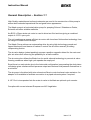
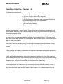
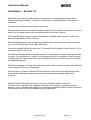
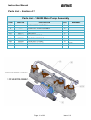
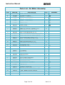
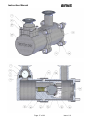
Instruction Manual
For
Maple 15 - Pump
Model 104009
Instruction Manual
Page 2 of 28
Issue: 2.2
Instruction Manual
Index
Section
1.1
1.2
1.3
1.4
General Description
Operating Principle
Specifications
Dimensions and Mounting Details
2.1
Important Safety Information
3.1
Installation - General
4.1
4.2
4.3
4.4
Parts Lists Main Pump
Parts Lists Air Motor
Parts Lists Fluid Section
Parts Lists Reference
5.1
5.2
5.3
Maintenance – Air Motor Assembly Procedure
Maintenance – Fluid Section Assembly
Maintenance – Final Pump Assembly
6.1
6.2
Maintenance - General
Maintenance - Fault Finding
7.1
7.2
Spare Parts Lists
Accessories
Page 3 of 28
Issue: 2.2
Instruction Manual
General Description – Section 1.1
High Quality materials and surface treatments are used in the construction of this pump to
ensure both extended operational life and good future appearance.
The Maple pump is a horizontal piston pump for pumping Solvent / Waterborne Paints,
Solvents and other suitable materials.
An Ø125 x 50mm stroke air motor is used to drive two fluid sections giving a combined
output of 0.375 L per cycle.
The unit combines an energy efficient air motor with low shear fluid section technology from
the range of Smart Electric Pumps.
The Maple Pump achieves a reciprocating drive by using high technology ground and
lapped steel spool and sleeve air valves to control the air motor reversal, providing
reciprocating motion.
The air valve design (patent pending) ensures a positive magnetic detent for the main and
pilot air valves thus removing the possibility for a stall condition.
The air motor also utilises the Binks Low Ice quick exhaust technology to prevent air valve
freezing conditions when high cycle speeds are employed.
Equal thrust on each stroke due to the horizontal configuration incorporating the dual piston
rod design gives a balanced fluid pressure output and reduces fluid pressure fluctuations to
a minimum.
The air pump is furnished with twin exhaust mufflers to control exhaust noise emission. An
adapter kit is available to facilitate connection to a piped exhaust system if required.
A 1/8” Port is incorporated into the main air valve to facilitate an optional cycle counter.
Complies with current relevant European and US Legislation
Page 4 of 28
Issue: 2.2
Instruction Manual
Operating Principle – Section 1.2
The Assembly comprises of:•
•
•
•
•
•
•
Central Air Piston and ‘change over’ Valves
2 off Quick Exhaust and muffler assembly
2 off Dynamic Chambers and Fluid Pistons
2 off Fluid Pressure Chambers each complete with Suction
and Pressure Ball Check Valve Assemblies
1 off Fluid Inlet Manifold
1 off Fluid Outlet Manifold
Support Bracket
The Pumps have horizontally opposed positive displacement pistons connected to a
common reciprocating air motor piston. The pneumatically driven piston actuates pilot air
control valves at the end of its travel producing an air logic signal to shuttle the spool valve
initiating the opposite stroke.
The air pilot valves contain no springs. They are operated by magnetic force and reset by
the main piston air supply and retained in position by a magnetic detent. The main spool
valve is air piloted and contains two exhaust ports. Both the pilot valves and the main spool
valve are easily removable.
There are no external air pilot hoses. The air logic and exhaust ports are internal. Simply
mounting the spool valve and the pilot valves assures that the logic circuits are connected
properly.
The air cylinder exhaust air is channelled through two independent quick exhaust valves to
minimises piston reversal time.
The “4-Ball” fluid section design refers to the two sets of ball checks. Each fluid chamber
has an inlet and outlet ball check, the inlet check is uniquely positioned in the piston saving
space and reducing the overall weight of the pump. The inlet and outlet ball checks are
connected by a common inlet manifold and outlet manifold respectively.
A bellows provides the fluid seal on the connecting rod within the inlet chamber, whilst a
main piston seal maintains the pump fluid pressure within the pressure chamber.
When the main piston seal starts to pass fluid due to wear, any leakage passes into the
inlet chamber.
Page 5 of 28
Issue: 2.2
Instruction Manual
Specification – Section 1.3
Specification
50 mm
1.97 ins
Pump Nominal Stroke
Pump Ratio
3:1
0..375 Litres
0.10 US Gall
Nominal Flow Volume / Cycle
Fluid Output @ 60 cycles/min
22.5 Litres / min
6.0 US Gall / min
Maximum Recommended Continuous Cycle Rate
20 Cycles /min
Maximum Recommended Intermittent Cycle Rate
40 Cycles /min
Fluid Inlet / Outlet Connections
1” Sanitary
0.17 SCFM (4.8 L/m) @ 45PSI (3.1 Bar)
0.33 SCFM (9.3 L/m) @ 90 PSI (6.2 Bar)
Air Volume / cycle
Air Flow @ 15 cycles/min 6 bar
Air Flow @ 30 cycles/min 6 bar
Air Quality ISO 8573.1 Class 3.3.2 # See Note
5 CFM (142 L/min)
10 CFM (283 L/min)
Dirt
5 microns
Water -20ºC@7bar (940ppm)
Oil
0.1mg/m³
21 Kg
46 Lb
Total Weight of Pump
# Note: Class 3.4.2 Air Quality (Refrigerant dried - water +3ºC@7bar) may be used,
however, above 15 cycles/min optional heavy duty mufflers 192821 or piped exhaust
system should be used.
Page 6 of 28
Issue: 2.2
Instruction Manual
Dimensions and Mounting Details – Section 1.4
For Piped Exhaust Air, remove mufflers and add
192803 Plug and Adapter 192779 for 1” NB Hose
Page 7 of 28
Issue: 2.2
Instruction Manual
Important Safety Information - Section 2.1
Directions for Working Safety
This Product has been constructed according to advanced technological standards and is operationally reliable. Damage may, however,
result if it is used incorrectly by untrained persons or used for purposes other than those for which it was constructed.
The locally current regulations for safety and prevention of accidents are valid for the operation of this product under all circumstances.
International, national and company safety regulations are to be observed for the installation and operation of this product, as well as the
procedures involved in maintenance, repairs and cleaning.
These instructions are intended to be read, understood and observed in all points by those responsible for this product. These operating
and maintenance instructions are intended to ensure trouble free operation. Therefore, it is recommended to read these instructions
carefully before start-up. Binks cannot be held responsible for damage or malfunctions resulting from the non-observance of the
operating instructions. These instructions including regulations and technical drawings may not be copied, distributed, used for
commercial purposes or given to others either in full or in part without the consent of Binks.
We reserve the right to alter drawings and specifications necessary for the technical improvement of this product without notice.
High Pressure/Electrostatic Warning
High pressure equipment can be dangerous if used incorrectly, serious bodily injury may occur if the following instructions are ignored.
Installation and maintenance should only be carried out by suitably qualified personnel.
1.
Before attempting any work on a high-pressure system ensure material pump, hydraulics, compressed air motor are isolated where
relevant.
2. Relieve all pressure from the system. Note: It is possible for pressure to get locked into a system, therefore, ensure all sections of
the system are checked thoroughly for remaining pressure.
3. Take care when releasing fittings
4. Always replace worn hoses immediately
5. Never plug a leak with your finger, adhesive tape or other stop gap devices
Always ensure equipment is suitably earthed before running, to avoid any chance of electrostatic build up.
Equipment Misuse Hazard
Equipment misuse can cause the equipment to rupture or malfunction and result in serious injury.
•
•
•
•
•
•
•
•
•
•
•
This equipment is for professional use only.
Read all instruction manuals, tags, and labels before operating the equipment.
Use the equipment only for its intended purpose.
Do not alter or modify this equipment. Use only genuine Binks parts and accessories.
Check equipment daily. Repair or replace worn or damaged parts immediately.
Do not exceed the maximum working pressure stated on the equipment or in the Technical Data for your equipment. Do not
exceed the maximum working pressure of the lowest rated component in your system.
Use fluids and solvents which are compatible with the equipment wetted parts. Refer to the Technical Data section of all
equipment manuals. Read the fluid and solvent manufacturer’s warnings.
Route hoses away from traffic areas, sharp edges, moving parts, and hot surfaces. Do not expose hoses to temperatures
above 82°C (180°F) or below —40°C (—40°F).
Wear hearing protection when operating this equipment.
Do not lift pressurized equipment.
Comply with all applicable local, state, and national fire, electrical, and safety regulations.
Page 8 of 28
Issue: 2.2
Instruction Manual
Important Safety Information - Section 2.1
Fire, Explosion and Electric Shock Hazard
Improper grounding, poor ventilation, open flames or sparks can cause a hazardous condition and result in a fire, explosion, or electric
shock.
When installed and operated in accordance with its instructions, the pump is approved for operation in Zone 1 (Europe) & Division 1
(North America), hazardous locations. (ATEX Cat 2)
•
•
•
•
•
•
•
•
•
•
•
Electrical equipment must be installed, operated, and serviced only by trained, qualified personnel who fully understand the
requirements stated in this instruction manual.
Ground the equipment and all other electrically conductive objects in the spray area. After grounding test with ohmmeter to
ensure earth continuity is 1 ohm or less.
Keep all covers tight while the motor is energized.
If there is any static sparking or you feel an electric shock while using this equipment, stop spraying/dispensing immediately. Do
not use the equipment until you identify and correct the problem.
Provide fresh air ventilation to avoid the build up of flammable fumes from solvents or the fluid being pumped.
Keep the pumping area free of debris, including solvent, rags, and gasoline.
Electrically disconnect all equipment in the pumping area.
Extinguish all open flames or pilot lights in the spray/dispense area.
Do not smoke in the spray/dispense area.
Do not turn on or off any light switch in the spray/dispense area while operating or if fumes are present.
Do not operate a gasoline engine in the spray/dispense area.
Hot Surface Hazard
•
•
The electric motor becomes hot during operation, and the heat may be transferred to other connected equipment. To reduce
the risk of burning yourself, do not touch the motor surfaces while it is operating.
Before servicing, allow the motor to cool.
Keep flammable materials and debris away from the equipment.
Pressurized Equipment Hazard
Spray from the gun/valve, hose leaks, or ruptured components can splash fluid in the eyes or on the skin and cause serious injury.
•
Do not point the gun/valve at anyone or at any part of the body.
•
Do not stop or deflect leaks with your hand, body, glove or rag.
•
Spraying/dispensing; clean, check, or service the equipment.
•
Tighten all fluid connections before operating the equipment.
•
Check the hoses, tubes, and couplings daily. Replace worn, damaged, or loose parts immediately. Permanently coupled hoses
cannot be repaired; replace the entire hose.
Toxic Fluid Hazard
Hazardous fluid or toxic fumes can cause serious injury or death if splashed in the eyes or on the skin, inhaled, or swallowed.
•
Know the specific hazards of the fluid you are using.
•
Store hazardous fluid in an approved container. Dispose of hazardous fluid according to all local, state and national guidelines.
•
Always wear protective eyewear, gloves, clothing and respirator as recommended by the fluid and solvent manufacturer.
Moving Parts Hazard
•
Keep clear of all moving parts when starting or operating the pump.
.
Page 9 of 28
Issue: 2.2
Instruction Manual
Installation – Section 3.1
Mount the pump securely and position the pump at a convenient height (below the lid
height of the paint container), to allow for maintenance, visual observation, and periodic
inspection.
The wall mount bracket is included with all pumps.
Exhaust silencer kits are available for these pumps if the air exhaust is required to be piped
away from the pump rather than exhausting locally through the mufflers.
The Pump Mounting Frame must be connected to a suitable earth ground to ensure that
there is no possibility of static build up.
Attach suitable flexible hoses (20 bar working pressure) to the inlet and outlet connections.
e.g. 25 mm NB Inlet and 25 mm NB Outlet hose.
Connect a suitable 3/8 NB air hose and ½” Pressure Filter Regulator to the air motor. (Filter
rated at minimum 1000 L/min)
No additional air lubrication is required as piston o-ring lubricant is applied during assembly
or repair. If an air lubricator is used to prolong piston seal life (for example continuous duty
at high pump cycle rates) then this must be maintained as the lubricant removes the piston
seal assembly grease.
Set the pump speed to a slow cycle rate and start the pump to remove any air from the fluid
circuit. Inspect for any air or fluid leaks.
Set the pump cycle rate to achieve the required paint volume and then adjust the system
back pressure regulator and pump air pressure to achieve the desired system fluid
pressure.
A Back Pressure Regulator should be mounted in the paint system return line.
The return line ‘back pressure’ regulator responds to the changes in system fluid flow
demand, (due to variable paint usage) by dynamically adjusting the paint flow rate returning
to the system paint tank, thus maintaining the set pressure.
Page 10 of 28
Issue: 2.2
Instruction Manual
Parts List – Section 4.1
Parts List - 104009 Main Pump Assembly
ITEM
PART No
DESCRIPTION
1
------
AIR MOTOR ASSEMBLY
1
2
------
FLUID SECTION ASSEMBLY
2
81
82
192777
192834
MUFFLER
INLET MANIFOLD
2
1
83
84
85
192835
192009
192206
OUTLET MANIFOLD
SANITARY CLAMP
SANITARY GASKET
1
4
4
Page 11 of 28
QTY
REMARKS
Issue: 2.2
Instruction Manual
Parts List - Air Motor Assembly
ITEM
PART No
3
0115-010102
161998
161993
161994
DESCRIPTION
QTY
REMARKS
MAIN AIR VALVE ASSEMBLY
Ø125 x 2 O-RING
Ø20.35 x 1.78 O-RING
Ø4.47 x 1.78 O-RING
1
2
2
4
161995
162707
162703
162704
Ø19.5 x 3.00 O-RING
PISTON SEAL
SHAFT SEAL
SHAFT BEARING
2
1
2
2
163920
165123
165135
165528
165960
M6 x 30 CAP HD SCREW (ST ST)
M10 SPRING WASHER (ST ST)
M10 PLAIN WASHER (ST ST)
M4 x 16 CAPHEAD SET SCREW (ST ST)
M12 X 40 CAP HD SCREW (ST ST)
4
4
4
4
8
165973
165965
165970
165971
M12 x 45 GRUBSCREW (ST ST)
M10 x 16 HEX HEAD SET SCREW (ST ST)
M4 PLAIN WASHER (ST ST)
Ø4 SPRING WASHER (ST ST)
1
4
4
4
192374
192579
RETAINING NUT
KNIFED BELLOWS
2
2
23
192831
CYLINDER
1
24
192830
192759
192832
165044
192763
END PLATE
PISTON SHAFT
PISTON
M12 SPRING WASHER
BELLOWS SPACER
2
2
1
8
2
PUMP BRACKET
PILOT SPOOL ASSEMBLY
VENT PLUG
2
2
2
EXHAUST ADAPTER
BELLOWS LEAK DETECTION HOSE
1/8R - 6MM PUSH IN ELBOW
1
1
2
4
5
6
7
8
9
10
11
12
13
14
15
16
17
18
19
20
21
22
25
26
27
28
29
30
31
32
33
34
192764
0115-010037
192799
192812
192814
192815
Page 12 of 28
Issue: 2.2
Instruction Manual
Parts List – Section 4.2
Air Motor Assembly
Page 13 of 28
Issue: 2.2
Instruction Manual
Parts List – Section 4.2
Parts List - 0115-010102 Main Air Valve Assembly
ITEM
PART No
DESCRIPTION
40
41
42
43
0115-010097
0115-010015
0115-010016
0115-010017
VALVE BLOCK ASSEMBLY
SPOOL & SLEEVE ASSEMBLY
BUMPER
MAGNET
1
1
2
2
44
45
46
0115-010018
192813
0115-010020
END CAP
QE VALVE CAGE
QEV DIAPHRAGM
2
2
2
47
48
49
50
0115-010021
0115-010049
0115-010073
171612
Ø36 x 1.5 O-RING
Ø20 x 2 O-RING
M4 x 12 BUTTON HD CAP SCREW
1/8” PLUG
2
2
8
1
51
52
171621
180584
1/4 “ PLUG
AIR INLET FITTING (3/8”)
1
1
Page 14 of 28
QTY
REMARKS
Issue: 2.2
Instruction Manual
Parts List – Section 4.2
0115-010102 Main Air Valve Assembly
Page 15 of 28
Issue: 2.2
Instruction Manual
Parts List – Section 4.3
Parts List – Fluid Section
ITEM
PART No
DESCRIPTION
55
160513
SPRING
1
56
57
58
59
165972
163972
165123
165087
M5 x 25 CAP HD SCREW
M6 x 20 CAP HD SCREW
M10 SPRING WASHER
M6 SPRING WASHER
5
4
8
4
60
61
165947
171788
M10 x 35 CAP HD SCREW
INLET BALL
8
1
62
63
192382
192827
OUTLET BALL
OUTLET CHECK
1
1
64
65
66
67
192826
192825
192822
192823
OUTLET CYLINDER
INLET CYLINDER
PISTON
PISTON KEEP PLATE
1
1
1
1
68
69
70
71
192629
192833
192632
192828
SPRING KEEP
SEAT
INLET SEAT
PISTON SEAL
1
1
1
1
72
73
192648
192712
Ø41.0 O-RING
Ø37.82 O-RING
1
2
Page 16 of 28
QTY
REMARKS
Issue: 2.2
Instruction Manual
Page 17 of 28
Issue: 2.2
Instruction Manual
Maintenance – Section 5.1 - Assembly Procedure
Pump Assembly – Air Motor
Ensure all parts are clean and degreased.
1. Push bearings (10) into end plates (24) and insert ‘O’ rings (4) into the large grooves,
applying a light coating of grease type #.
2. Apply light coating of grease type # to the seal groove of the piston and insert the ‘O’
ring portion of the piston seal (8), apply a little more grease to the top of the ‘O’ ring.
Carefully fit the seal strip into the piston groove (fit one half of the seal into the groove
and then apply pressure to the o-ring seal already in the groove, and pull the remaining
seal into the groove, being careful to avoid unduly stretching the seal strip).
3. Insert grub screw (16) into one of the piston shafts (25) use Loctite studlock 2701 and
tighten to 45Nm. Mount this through the piston (26) and screw on the other shaft (25)
again using loctite studlock 2701 and tighten to 100Nm. Clean off any residue of loctite.
4. Lightly apply grease type # to the inside of the air motor cylinder (23), insert the piston
and shaft sub-assembly into the cylinder at a 45° angle and turn the piston until it is
inline with the cylinder.
5. Insert the cylinder end plate sub-assemblies over lightly greased # shafts and into the
cylinder. Press parts lightly together, making sure that the Main Valve (3) mounting
surfaces are inline.
6. Insert 4 off M12 Cap Head Screws (15) and spring washers
(27) into each cylinder end plate sub-assembly to secure the
cylinder, tighten in ‘cross over’ sequence together to 40Nm.
7. Apply grease type # onto the shafts and gently push over the
shaft seal (9), lips pointing inwards (Use Tool 502608), push
the seal fully home into the end plate. Then fit the bellows
retainer (28) over the shafts, smaller hole facing inwards.
8. Screw 502382 assembly spigot onto the piston shaft
(25).Using tool 502377 push the bellows (21) over the
assembly spigot until the bellows internal spigot locates into
the shaft groove. (Using the tool prevents damage to the
convolutions)
9. Smear a film of loctite 572 over the nose of the bellows then
thread the nut (20) onto the bellows using tool 502377 to push
against the nut ensuring the thread starts squarely. Grip the
bellows and turn the nut with a 1” A/F spanner until positive
resistance is felt. The distance between the nut and the first
convolution should be 0 to 1mm.
10. Remove 502382 assembly spigot.
11. Fit mounting brackets (29) to the end plates using 4off M10 Hex Hd screws (17) and
washers (12) & (13) tighten to 35Nm. Use loctite 243 on threads.
12. Install vent plugs (31) and elbows (34) to the end plates
Page 18 of 28
Issue: 2.2
Instruction Manual
Maintenance – Section 5.1 - Assembly Procedure
Pump Assembly – Air Motor – Control Valves
Pilot Valves (30) - Lightly grease threads and o-rings (grease type #) fit the two pilot valve
assemblies into the end plates. Tighten to 0.4Nm (do not over tighten this will damage the
valve assembly)
Main Valve (3):1. Ensure all parts are free from contamination
especially the magnets (43)
2. Lightly grease valve bore of housing (40) and oring of spool assembly (41) Use grease type #
3. Carefully insert the spool assembly into the
housing until centrally positioned.
4. Insert bumpers (42) into each end of the spool
housing.
5. Insert magnets (43) into end cap (44) then fit oring (48) lubricate with grease type # and
assemble into housing
6. Fit seals (47) into housing
7. Position diaphragm (46) into cage (45) and fit into
housing (locate cages with relevant pin positions,
ensure diaphragm is centrally located)
8. Secure with screws (49)
9. Ensure threaded plugs (50) and (51) are in
position
Assembly Main Valve to Air Motor
1. Fit 2 off o-rings (5) and 4off o-rings (6) into air motor end plates (24)
2. Secure main valve assembly (3) onto the end plates with 4 off cap head screws (11)
3. Fit sealing o-rings (7) onto the exhaust cage (45) lightly grease #
4. Fit exhaust adapter (32) using screws (14) and washers (18) & (19) onto the main valve.
Page 19 of 28
Issue: 2.2
Instruction Manual
Maintenance – Section 5.2 - Assembly Procedure
Pump Assembly – Fluid Section - Ball Checks
Assemble the Piston
1. Insert spring (55) and spring keep (68) into
the piston
2. Place the ball (61) against spring keep.
3. Fit the ‘O’ ring (72) and inlet seat (70) into
the piston (66).
4. Fit piston keep plate (67) and assemble with
5 off M5x25 caphead screws (56) use
Loctite 222 on the threads. Tighten evenly to
8Nm.
Assemble the outlet ball check
1. Place ball (62) into outlet check (63)
2. Fit o-ring seal (73) and outlet seat (69) into
outlet check.
3. Fit o-ring seal (73) onto outlet cylinder (64)
4. Position the outlet check onto the outlet
cylinder.
5. Secure with of 4 off M6 x 20 caphead
screws (57) (Grease threads) and washers
(59). Tighten evenly to 10Nm.
Page 20 of 28
Issue: 2.2
Instruction Manual
Maintenance – Section 5.3 - Assembly Procedure
Pump Assembly – Fluid Section / Air Motor
1. Mount inlet cylinders (65) onto air motor end plates and over each shaft and bellows.
Secure loosely with lightly greased 4off M10x35 cap head screws (60) and 4off Ø10
washers (58). Do not tighten at this stage as this may lead to bellows damage when
assembling the piston to the shaft.
2. Apply loctite 243 to the piston shaft threads
and screw the piston assemblies onto shafts,
tighten up to 50 Nm. Note: If both fluid
sections are being assembled tighten by
holding one piston with its 14mm hexagon
socket and torque the other piston using its
socket.
4. Lightly grease with type # the pistons and fit
the piston seals (71), wear lip pointing away
from the shaft thread.
5. Fit outlet cylinder sub-assembly over the seal,
secure with lightly greased 4off M10x35
caphead screws (60) and assemble with 4off
Ø10 washers (58) to hold the cylinders
together. Tighten evenly all the cap head screws to 40Nm.
6. Tighten the caphead screws holding the inlet cylinder to the air motor to 40Nm
7. Mount inlet (82) and outlet (83) manifold to the fluid sections using clamps (84) and
seals (85) to orientation required.
8. Install mufflers (81) into exhaust adapter. Alternatively hose fitting (192802) and 1” plug
(192803) can be fitted where piped exhaust is required.
Grease Type #
AGMD-010 - Kluber Isoflex Topas 52
Page 21 of 28
Issue: 2.2
Instruction Manual
Maintenance – Section 5.4 - Disassembly Procedure
Removal of a Single Fluid Piston
Slide Inlet Cylinder
out to expose shaft
Hold Shaft with
16mm Spanner
Turn Piston with
14mm Allen Key
Page 22 of 28
Issue: 2.2
Instruction Manual
Maintenance – Section 6.1 – General
The working life and thus the expected life prior to replacement of parts within a Paint Pump
are greatly affected by three main factors: •
•
•
Abrasiveness of Fluid Pumped
Pump Duty Cycle
Fluid Pressure Output requirement
Maintenance Schedule
Inspection
Daily
Operation
Check for any general fluid or air leakage.
Inspect Pump for Correct operation
Weekly
Check for any excessive mechanical noise
Check for excessive fluid pressure pulsation
6 Monthly Test
12 to 36 Months
(Typically 10 million
Pump Cycles
dependant on air
quality and
abrasiveness of the
paint used)
Perform a pump stall test to ensure correct operation.
• If pump does not stall check fluid piston seals and ball
checks, replace as required.
• If air is escaping through exhaust check air motor piston seal
and quick exhaust diaphragm, replace as required.
Replace Air Piston seal
Replace shaft seals & bearings
Air Motor Seal Kit
Inspect and replace if required:Pilot Air Valves
Main Air Valve Parts
Control Valve Overhaul Kit
Replace Fluid Piston Seal
Replace Balls and Seats
Replace Bellows
Page 23 of 28
Fluid Piston Seal Kit
or
Fluid Section Overhaul Kit
Issue: 2.2
Instruction Manual
Maintenance – Section 6.2 – Fault Finding
Symptom
Possible Cause
Remedy
Pump will not
‘Prime’
a. Air getting into the suction
hose/manifold
b. Worn piston seals
c. Ball checks not seating correctly
a. Check seals and hose connections
b. Replace piston seals
c. Inspect, clean/replace balls/seats
Pump will not run
a. No Air or Fluid supply
a. Check air and fluid supply ball valves
and supply hoses.
b. Replace Piston seal
c. Switch/interchange pilot valves to
isolate faulty pilot valve and
clean/replace.
d. Check clean/replace Air valve.
e. Check for constant exhaust air when
pump is not running. Check/replace
QE diaphragms
f. Inspect, clean and/or replace balls
and seats.
b. Air piston seal worn.
c. Pilot valve assemblies inoperable.
d. Main air valve inoperable
e. QE diaphragm defective
f.
Ball checks not seating
Pump runs but has a. Air getting into fluid line, air supply
excessive pulsation
restricted.
b. Obstructed fluid ball checks.
c. Worn piston seals. Worn/failed air
motor shaft seals. Worn/loose air
motor shaft seal components. Worn
fluid piston and/or seal.
d. Air exhaust restricted.
e. Surge eliminator malfunction
a. Check seals and hose connections.
Check air supply
b. Remove, clean, and inspect seat,
ball, and ball cage. Replace if
suspect or worn.
c. Replace piston seal. Disassemble
pump as required to replace all seal
components on both sides.
d. Check QE diaphragms and exhaust
outlet.
e. Check surge eliminator for correct
operation.
Paint leaking into
detection hose (33)
Air bleeding from
vent plug (31)
a. Replace bellows seal (21)
b. Check air motor shaft seal (9),
replace as necessary
a. Bellows seal failure
b. Air motor shaft seal leaking
Page 24 of 28
Issue: 2.2
Instruction Manual
Spare Parts List - Section 7.1
Recommended Replacement Spares Kits for Maple 15 Pump
Kit No.
Part No.
250625
250626
Description
Remarks
Fluid Piston Seal Kit
Fluid Piston seals
Fluid O-rings
Ball Check Springs
Manifold seals
Fluid Section Overhaul Kit
Fluid Piston seals
Fluid O-rings
Ball Check Springs
Manifold seals
Balls and Seats
Bellows
250627
Air Motor Seal Kit
Air Piston Seals
Shaft seals and bearings
All O-rings
QEV diaphragms
250628
Control Valve Kit
Pilot Valves inc O-rings
Main Valve inc O-rings
Check Main Parts List for details of individual Kit Contents
Page 25 of 28
Issue: 2.2
Instruction Manual
Accessories - Section 7.2
Accessories / Maintenance
Part No.
Description
192206
1” Sanitary Gasket
192009
1” Sanitary Clamp
192532
1” Sanitary - 1” BSPT F Adapter
502608
Seal Insertion Tool
502377
Bellows Assembly Tool
502382
Bellows Assembly Spigot
AGMD-010
Remarks
For Shaft seal (9)
Kluber Isoflex Topas NB 52 (Grease type #)
50 ml Tube
192779
Exhaust Tube Adapter (1” NB hose)
For piped exhaust
192803
1” Manifold Plug
For piped exhaust
192821
1” BSP Heavy Duty Mufflers
Recommended for high pump
pressures and cycle rates
Page 26 of 28
Issue: 2.2
Instruction Manual
Page 27 of 28
Issue: 2.2
Instruction Manual
Justus-von-Liebig-Straße 31, 63128 Dietzenbach. DE
Tel. +49 (0) 6074 403 1 Fax. +49 (0) 607 403 300
General e-mail: [email protected]
Ringwood Road, Bournemouth, Dorset BH11 9LH. UK
Tel. +44 (0)1202 571 111 Fax. +44 (0)1202 573 488
General e-mail: [email protected]
163-171, Av. des Auréats, 26014 Valence cedex. FR
Téléphone : +33 (0) 4 75 75 27 53 Télécopie: +33 (0) 4 75 75 27 79
General e-mail: [email protected]
USA Canada Customer Service
195 Internationale Blvd.
Glendale Height,IL 60139
630-237-5000
Toll Free Customer Service and
Technical Support 800-992-4657
Toll Free Facsimile 800-246-5732
Binks registered office Finishing Brands Germany GmbH Justus-von-Liebig-Straße 31, 63128 Dietzenbach. Amtsgericht Offenbach HRB 43560
Page 28 of 28
Issue: 2.2