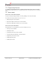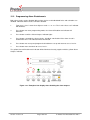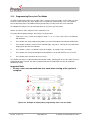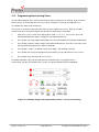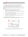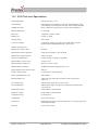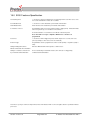
1
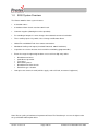
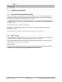
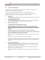
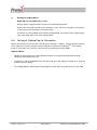
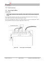
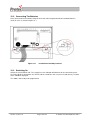
3200 NON-ADDRESSABLE
FIRE ALARM CONTROL PANEL
INSTALLATION, COMMISSIONING AND
MAINTENANCE MANUAL
Protec Fire Detection PLC, Protec House, Churchill Way, Nelson, Lancashire, BB9 6RT.
Telephone:
Fax:
Web:
Email:
+44 (0) 1282 717171
+44 (0) 1282 717273
www.protec.co.uk
[email protected]
Document Revision Details
Issue
Author
Date
0
Modification Detail
Document Creation
NH
23/06/05
1
Remove reference to fire link interface
RB
18/04/07
2
Refer to ECN3367
NH
23/05/13
93-331-73 Issue 2
Page 2 of 32
© Protec Fire Detection PLC 2013
Table of Contents
1.0
3200 SYSTEM OVERVIEW..................................................................................................................................... 4
2.0
IMPORTANT NOTES – PLEASE READ ................................................................................................................. 5
3.0
ITEMS SUPPLIED WITH THE 3200 PANEL .......................................................................................................... 6
4.0
CABLING REQUIREMENTS .................................................................................................................................. 7
4.1
4.2
DETECTOR, ALARM AND AUXILIARY WIRING...................................................................................................... 7
MAINS WIRING .................................................................................................................................................... 7
5.0
INSTALLATION PROCEDURE .............................................................................................................................. 8
6.0
TESTING OF CABLING PRIOR TO CONNECTION............................................................................................... 9
7.0
DETECTOR CIRCUIT CONNECTIONS ................................................................................................................ 10
8.0
ALARM CIRCUIT CONNECTIONS ....................................................................................................................... 11
9.0
AUXILIARY INPUT AND OUTPUT WIRING ......................................................................................................... 12
9.1
9.2
9.3
9.4
9.5
10.0
10.1
10.2
10.3
11.0
11.1
11.2
12.0
12.1
12.2
12.3
12.4
12.5
12.6
KEYSWITCH INPUT ............................................................................................................................................. 12
REMOTE ALARM INPUT ...................................................................................................................................... 12
CLASS CHANGE INPUT ....................................................................................................................................... 12
GLOBAL FAULT OUTPUT .................................................................................................................................... 12
GLOBAL FIRE OUTPUT ....................................................................................................................................... 12
COMMISSIONING ................................................................................................................................................. 13
CONNECTING THE MAINS ................................................................................................................................... 13
CONNECTING THE BATTERIES ........................................................................................................................... 14
SWITCHING ON .................................................................................................................................................. 14
PROGRAMMING OVERVIEW .............................................................................................................................. 15
ACCESS LEVELS ................................................................................................................................................. 15
ZONE PROGRAMMING CHOICES ......................................................................................................................... 16
PROGRAMMING DETAILS .................................................................................................................................. 17
PROGRAMMING ZONE DISABLEMENTS............................................................................................................... 18
PROGRAMMING ALARM DISABLEMENTS............................................................................................................ 19
PROGRAMMING ZONES INTO TEST MODE .......................................................................................................... 20
PROGRAMMING COINCIDENCE ZONES................................................................................................................ 21
PROGRAMMING NON-LATCHING ZONES ............................................................................................................ 22
PROGRAMMING THE DETECTION ZONE END OF LINE MONITORING TYPE .......................................................... 23
13.0
FAULT RECTIFICATION GUIDELINES ............................................................................................................... 24
14.0
3200 TECHNICAL SPECIFICATION .................................................................................................................... 25
15.0
3200 FEATURES SPECIFICATION ...................................................................................................................... 26
APPENDIX 1 - ACCESSORIES AVAILABLE FOR THE 3200. ....................................................................................... 27
APPENDIX 2 - 3200 SPARES LIST.................................................................................................................................. 28
APPENDIX 3 - 3200 MAIN PCB. DETAILS ...................................................................................................................... 29
APPENDIX 4 - 3200 PROGRAMMING QUICK REFERENCE GUIDE ............................................................................. 30
93-331-73 Issue 2
Page 3 of 32
© Protec Fire Detection PLC 2013
1.0
3200 System Overview
The Protec 3200 fire alarm system features:
•
2 detection zones.
•
2 monitored alarm circuits rated at 150mA each.
•
Common negative (allowing three wire operation).
•
Re-sounding of outputs if a zone changes from automatic to manual activation
•
Three auxiliary inputs: Keyswitch, Class Change and Remote Alarm.
•
Global Fire and Global Fault clean contact connections.
•
Monitored Auxiliary 24V output (Overload Protected, 100mA maximum).
•
Capacitive or resistive detector circuit end of line monitoring (programmable).
•
Extensive range of engineering functions accessed via 5 digit entry codes:
•
•
•
•
•
•
•
Disablement of zones.
Coincidence operation.
Test zones.
Non-latching zones.
Disablement of alarm circuits.
End of line type selection.
Low quiescent current of 15mA (24V dc supply, mains fail fault, no external equipment).
Note: Due to a policy of continuous improvement Protec Fire Detection plc. reserve the right to alter
the specification without prior notice.
93-331-73 Issue 2
Page 4 of 32
© Protec Fire Detection PLC 2013
2.0
Important Notes – PLEASE READ
•
THE FIRE ALARM PANEL AND ITS ASSOCIATED CONNECTIONS MUST BE INSTALLED,
COMMISSIONED AND MAINTAINED BY A SUITABLY SKILLED AND COMPETENT PERSON.
•
THIS EQUIPMENT MUST BE EARTHED.
•
THIS EQUIPMENT IS NOT GUARANTEED UNLESS INSTALLED AND COMMISSIONED IN
ACCORDANCE WITH CURRENT NATIONAL STANDARDS.
•
THIS EQUIPMENT HAS BEEN DESIGNED AND MANUFACTURED TO CONFORM WITH
THE REQUIREMENTS OF ALL APPLICABLE EU COUNCIL DIRECTIVES.
•
THIS MANUAL MUST BE THOROUGHLY READ AND UNDERSTOOD BEFORE
INSTALLATION AND COMMISSIONING OF THIS EQUIPMENT IS UNDERTAKEN.
93-331-73 Issue 2
Page 5 of 32
© Protec Fire Detection PLC 2013
3.0
Items Supplied with the 3200 panel
•
Installation, Commissioning and Maintenance manual.
•
User manual.
•
Mounting template.
•
Accessory pack, comprising:
•
•
•
•
•
•
•
2 x 100µF/22Ω detector circuit end of line units
2 x 10k alarm circuit end of line units
1 x red battery lead
1 x black battery lead
1 x inter-battery connection lead
1 x 1 Amp HRC power supply fuse
1 x 1 Amp anti-surge battery fuse
93-331-73 Issue 2
Page 6 of 32
© Protec Fire Detection PLC 2013
4.0
Cabling Requirements
4.1
Detector, Alarm and Auxiliary Wiring
All external wiring associated with the system must conform to the current I.E.E Regulations and
cabling must conform to the relevant BS specifications. ECA recommended Cable Separation for
Electromagnetic Compatibility in Buildings must be followed.
To comply with EMC regulations Protec recommends the use of screened cabling throughout the
installation. The screens must be securely connected to the screwed earthing studs provided inside
the 3200 enclosure.
Screened cables that are suitable for wiring are:
TM
TM
TM
MICC (Pyro ), Pirelli FP200 , FireTuff , or any other cable which complies with BS 6387
(categories C, W, Z).
Proper glanding of the cable is vital for the correct performance of the system.
4.2
Mains Wiring
The 3200 requires a mains supply exclusive to the panel that uses fixed three core wiring (between
2
2
0.75mm and 2.5mm ) which is fed from an isolating fused spur, fused at 3A.
Unauthorised operation of the mains supply should not be allowed and the fused spur should be
labelled “FIRE ALARM: DO NOT SWITCH OFF”
Important Note:
Do not connect the mains wiring to the control panel until all other connections (detector
circuits, alarm circuits, auxiliary inputs/outputs) have been checked.
93-331-73 Issue 2
Page 7 of 32
© Protec Fire Detection PLC 2013
5.0
Installation Procedure
The 3200 fire alarm panel circuit boards are housed in a metal enclosure. This enclosure has a
lockable metal front door (holding the display board).
The panel can be surface or flush mounted (a bezel is required for flush mounting).
The panel must be located internally in an area that is not subject to dampness, extremes of
temperature or physical abuse. The environmental limits are given in Section 21
1)
Unpacking
After opening the box, remove the installation template from the packaging, leaving the 3200
in the cardboard box for protection.
2)
Preparing the Mounting Position
Use the installation template in conjunction with a spirit level to mark out the fixing locations
for the panel. Drill and plug the three mounting holes previously marked.
3)
Removal of the Main Board.
NOTES ON ANTI-STATIC HANDLING OF THE PCBs
Before handling any of the circuit boards in the 3200 it is vital that any operatives
discharge themselves of any static charge that may have built up on them. This can be
done by momentarily touching a solid earth point (a non-painted part of a radiator, for
example).
Handle the PCB. by its sides and DO NOT touch the electronic components.
The PCB. should be stored in a clean, dry place away from the place of work. Retain the
PCB. in a cardboard box for safety until it is required.
Disconnect the 16 way display board ribbon cable from the main PCB. Take care not to strain
the PCB.
Remove the supplementary earth cable from the mains terminal block.
Unscrew the five posidrive screws on the main PCB. Then remove the PCB, the screws (and
any washers) and the power supply insulation sheet and place them in the cardboard box for
protection.
4)
Preparing and Fixing the Unit
Using the installation template, mark out suitable positions for cable entry on the top of the
enclosure (not behind the main board or battery locations). The mains cable entry position
should be kept away from other system cabling.
Drill out the cable entry positions and mount the enclosure at the position prepared in (2)
whilst feeding the cables into the enclosure.
Ensure any metal swarf is completely removed from the enclosure before the main PCB. is refitted.
93-331-73 Issue 2
Page 8 of 32
© Protec Fire Detection PLC 2013
5)
Refitting of the Main Board
NOTE: Do not over-tighten any screws.
Refit the power supply insulation sheet over the PCB mounting pillars.
Replace the main PCB and refit the five posidrive screws. Ensure the top right screw includes
a metal star washer to maintain earth connectivity.
Reconnect the 16-way ribbon cable from the display board, and reconnect the supplementary
earth connection to the mains input terminal block.
6.0
Testing of Cabling Prior to Connection
Before connecting any external cables to field device (detectors, sounders, auxiliary inputs or outputs),
TM
or the 3200, tests must be carried out using a 500V dc insulation tester (Megger ). The readings
between each cable core, and each core and earth should be greater than 10MΩ.
Important Notes:
•
Equipment connected to the cabling during insulation tests could be damaged with the high
voltages produced during the test.
•
Field devices and the 3200 MUST NOT be connected when high voltage insulation tests are being
performed on the cabling.
•
The cabling must be completely discharged prior to connection to any field devices or the 3200.
93-331-73 Issue 2
Page 9 of 32
© Protec Fire Detection PLC 2013
7.0
Detector Circuit Connections
Figure 7 shows a typical connection regime for a detector zone on the 3200.
Figure 7.0
Typical 3200 Detector Connection
•
Ensure the length of the zone wiring is no more than 500 metres.
•
Ensure the resistance of each conductor is no more than 15Ω.
•
Ensure the capacitance of the zone wiring is no more than 0.27µF (micro-Farads)
when no end of line capacitor is present.
•
The end of line unit (8.2kΩ resistor or 100µF/22Ω network) must be placed at the very end of the
detector zone wiring, to ensure the whole zone is monitored.
•
Spurs should not be connected from the zone wiring, as a spur cannot be monitored for open
circuit faults.
•
To ensure compliance with EN54 Part 2 each detector base must include a series low voltage
drop diode, so that manual call points following a removed detector still function correctly. Protec
S3000 bases incorporate the diode as standard.
•
Manual call points must incorporate a series resistor to ensure the zone does not enter a short
circuit fault condition when the manual call point is activated. If the panel is to be able to
distinguish between automatic and manual zone activation. The resistor value in the manual call
point must be 180Ω. In retrofit situations, values up to 560Ω can be used but the ‘MCP Fire’
indication may not be given in all cases.
Protec 3100 manual call points incorporate the series resistor as standard.
93-331-73 Issue 2
Page 10 of 32
© Protec Fire Detection PLC 2013
8.0
Alarm Circuit Connections
The 3200 has two alarm circuit outputs, rated for continuous use at 150mA and protected from overload by an auto resetting thermal ‘fuse’. The ‘fuse’ will reset when the cause of overload has been
removed and the alarm output has been de-activated.
Figure 8 shows typical connections for a alarm circuit.
Figure 8.0
Typical Alarm Circuit Connection.
•
Ensure the length of the alarm circuit wiring is no more than 500 metres.
•
Ensure the capacitance of the alarm circuit wiring is no more than 0.27µF (micro-Farads).
•
The 10kΩ end of line resistor must be connected at the very end of the alarm circuit wiring, to
ensure the whole line is monitored for open circuit faults.
•
Spurs should not be connected from the alarm wiring, as the spur cannot be monitored for open
circuit faults.
•
Only polarised and suppressed sounders should be used on the 3200 alarm circuits. Failure to
use polarised sounders will result in an alarm circuit fault. All Protec S3000 sounders are polarised
and suppressed as standard.
•
Efforts should be made to evenly spread the sounder load across the two alarm circuits, to avoid
overloading either of the alarm outputs.
•
It is acceptable to connect alarm circuits 1 and 2 in parallel (to obtain a drive rating of 300mA
continuous), however the end of line resistor value must be changed to 4k7Ω 1/2W 5%. This is
detailed in figure 8.1
1
2
Figure 8.1
93-331-73 Issue 2
Enhanced Alarm Circuit Drive Details
Page 11 of 32
© Protec Fire Detection PLC 2013
9.0
Auxiliary Input and Output Wiring
The auxiliary input connections (Keyswitch, Remote Alarm and Class Change) and auxiliary output
connections (Global Fault and Global Fire) should be wired in screened cable. The screen should be
securely connected to the screwed earthing posts provided in the 3200.
9.1
Keyswitch Input
The keyswitch input is active when a short circuit (less than 50Ω) is connected across the keyswitch
terminals.
In the standard 3200 this is an alternate method of accessing level 2 functions if the code entry feature
is not required.
The keyswitch wiring should be kept local to the 3200.
9.2
Remote Alarm Input
The remote alarm input is active when a short circuit (less than 50Ω) is placed across the remote
alarm terminals. When active the 3200 will activate alarm outputs, fast pulse the internal buzzer and
illuminate the ‘General Fire’ indicator. The Global Fire output is NOT activated.
9.3
Class Change Input
The class change input is active when a short circuit (less than 50Ω) is connected across the Class
Change terminals. When active the 3200 will activate alarm outputs continuously. The Global Fire
output is NOT activated.
9.4
Global Fault Output
The Global Fault output is a set of Volt free relay changeover contacts (rated at 1A 24V dc max.) to
allow interfacing to other equipment. The contacts are normally activated (the N/C and COM contacts
are high resistance) and will release when the 3200 detects a fault.
9.5
Global Fire Output
The Global Fire output is a set of Volt free relay changeover contacts (rated at 1A 24V dc max.) to
allow interfacing to other equipment. The contacts are normally released (the N/C and C contacts are
low resistance) and operate as follows:
The Global Fire output WILL activate if:
•
•
A standard zone has activated (MCP or automatic)
A coincidence zone has expired, or the second zone has activated
The Global Fire output WILL NOT activate if:
•
•
•
•
A remote alarm activation occurs
A zone in test mode is activated
A non-latching zone is activated
The Sound Alarms button is pressed in access level 2 or 3
93-331-73 Issue 2
Page 12 of 32
© Protec Fire Detection PLC 2013
10.0 Commissioning
10.1
Connecting the Mains
Important Note:
•
Pay particular attention that the earth cable is firmly connected to the earth terminal of the
power supply, and that the earth strap from the main PCB. to the main panel metalwork is
sound.
After making and checking the connections to the control panel detailed in previous sections, the
power supply may be connected to the incoming mains supply.
Ensure the fused double pole isolator is in the ‘OFF’ position then connect the incoming mains cable
to the appropriate terminals on the power supply PCB (see figure 12.0).
Figure 12.0
93-331-73 Issue 2
Power Supply Terminal Details
Page 13 of 32
© Protec Fire Detection PLC 2013
10.2
Connecting The Batteries
Next, connect two new and fully charged 12V 2.2Ah Valve Regulated Sealed Lead Acid Batteries
(SLA) in series as shown in figure 12.1
Figure 12.1
10.3
Installation of Standby batteries
Switching On
Switch the fused isolator ‘ON’. The ‘Supply Present’ indicator will illuminate on the front of the panel.
Assuming all other connections are correct and the end of line units are present (and correct), no other
faults should be displayed.
The 3200 is now ready to be programmed.
93-331-73 Issue 2
Page 14 of 32
© Protec Fire Detection PLC 2013
11.0 Programming Overview
The 3200 has many programming features, making it extremely flexible. These can be accessed by
users at different authorisation levels. The programming features and authorisation levels are detailed
below.
11.1
Access Levels
Access Level 1 (User code not entered)
The panel’s front panel display indicators are visible, providing a clear status of the 3200.
The functions that may be performed at access level 1 are:
•
Muting of the panel’s internal buzzer.
•
Entry of the 5 digit user code to access level 2 functions.
•
Entry of the 5 digit engineer code to access level 3 functions.
Access Level 2 (User code entered)
Only authorised users are permitted access to level 2 functions, these are:
•
Silencing an alarm condition.
•
Sounding the alarms.
•
Resetting the panel after an alarm activation.
•
Testing the front panel indications, and internal buzzer.
•
Programming a zone into test mode.
•
Disabling detector circuits.
•
Disabling alarm circuits.
93-331-73 Issue 2
Page 15 of 32
© Protec Fire Detection PLC 2013
Access Level 3 (Engineer Controls)
Only engineers are permitted access to level 3 functions, these are:
•
All level 2 functions, plus
•
The programming of coincidence zones.
•
The programming of non-latching zones.
•
The programming of the detector circuit end of line type (capacitive or resistive).
11.2
Zone Programming Choices
Each zone of the 3200 may be programmed in the following manner.
•
Non-latching mode.
•
Coincidence mode.
•
Test mode.
Please not that a zone can only be programmed with one of the choices (ie. a zone cannot be set-up
as non-latching and coincidence) non-latching mode overrides coincidence mode.
Test mode overrides all other programming.
93-331-73 Issue 2
Page 16 of 32
© Protec Fire Detection PLC 2013
12.0 Programming Details
In general the front panel buttons and some indications have the following alternate functions when
the 3200 is in programming mode.
When Access Level 3 programming functions are being performed the 'Level 3 Accessed' indicator will
be illuminated and the ‘Supply Present’ indicator will flash.
Button 1
Button 2
Button 3
Button 4
Toggle zone 1 state.
Toggle zone 2 state.
Scroll.
Back / Exit / Program.
General Test Indicator
General Disablement
Alarm Outputs Disabled
Programming of zones into test mode
Programming of zone disablements
Programming of alarm disablements
Alarm Fault
PSU Fault
Aux 24V. Fault
Programming of EOL. type
Programming of non-latching zones
Programming of zones into coincidence
93-331-73 Issue 2
Page 17 of 32
© Protec Fire Detection PLC 2013
12.1
Programming Zone Disablements
One or both of its detector zones can be disabled. When a zone is disabled both faults and activations
are inhibited.
1.
From access level 1 enter the 5 digit user code 1 3 4 4 2. The ‘Level 2 Accessed’ indicator
will illuminate.
2.
Press button 2 once – The ‘General Disablement’ indicator will illuminate to show the zone
disablement option is selected (the normal front panel display is temporarily replaced with the
programming display). Any current disablements will be displayed on the zone fire indicators.
3.
Press button 1 (zone 1) or button 2 (zone 2) to toggle - disabled / not disabled.
4.
Press button 4 to accept and program the disablement set-up and return to access level 2.
5.
Press button 4 to return back to access level 1.
The yellow ‘General Disablement’ indicator will be illuminated steady, together with the yellow
disablement indicator for the relevant zone(s).
Figure 14.0. Example of the display when disabling zone 1.
93-331-73 Issue 2
Page 18 of 32
© Protec Fire Detection PLC 2013
12.2
Programming Alarm Disablements
Both alarm circuits can be disabled. When alarm circuits are disabled both faults and activations are
inhibited. Individual Alarm circuits cannot be disabled.
1.
From access level 1 enter the 5 digit user code 1 3 4 4 2. The ‘Level 2 Accessed’ indicator
will illuminate.
3.
Press button 2 to enter programming mode, the 'General Disablement' indicator will
illuminate.
4.
Press button 3 until the 'Alarm Outputs' indicator lights.
5.
Press button 1 to toggle the alarm circuits - disabled / not disabled. If the alarm circuit is
disabled the zone 1 fire indicator will be illuminated.
6.
Press button 4 to accept and program the disablement set-up and return to access level 2.
7.
Press button 4 to return back to access level 1.
The yellow ‘General Disablement’ indicator will be illuminated steady, together with the yellow ‘Alarm
Outputs’ indicator.
Figure 14.1. Example of the display when disabling the alarm outputs.
93-331-73 Issue 2
Page 19 of 32
© Protec Fire Detection PLC 2013
12.3
Programming Zones Into Test Mode
To aid the required fire alarm test schedule, zones can be put into ‘test mode’. In this mode, an alarm
on the test zone activates the alarm outputs for 4 seconds then automatically resets. This allows a
zone of detectors to be tested without having to manually reset the panel after each activation.
The Global Fire Contacts are not activated when the test zone goes into alarm.
Alarms on non-test zones will prevent the automatic reset.
The procedure for programming a zone into test is given below.
1.
From access level 1 enter the 5 digit user code 1 3 4 4 2. The ‘Level 2 Accessed’ indicator
will illuminate.
2.
Press button 2 to enter programming mode, the 'General Disablement' indicator will illuminate.
3.
Press button 3 until the 'General Test' indicator lights. Any zones currently in test mode will be
displayed on the zone fire indicator.
4.
Press button 1 (zone 1) or button 2 (zone 2) to toggle - test mode / not in test mode.
5.
Press button 4 to accept and program the disablement set-up and return to access level 2.
6.
Press button 4 to return back to access level 1.
The yellow ‘General Test’ indicator will be illuminated steady, showing that at least one zone has been
programmed into test mode. Any zones programmed into test mode will have their test indicator
illuminated steady.
Important Note:
• Ensure zones are removed from test mode when testing of the system is
complete.
Figure 14.2. Example of display when programming zone 2 into test mode.
93-331-73 Issue 2
Page 20 of 32
© Protec Fire Detection PLC 2013
12.4
Programming Coincidence Zones
Note. The 3200 will no longer be EN54 compliant if zones are programmed as coincidence
zones.
It is possible to program the zones as coincidence zones. This mode is used where the consequence
of a false alarm is onerous (for example if the panel is connected to an extinguishing system). In this
case, both zones must activate before the alarms sound or the Global Fire Contacts activate.
When only one coincidence zone activates the panel will flash the relevant zone indicator, fast pulse
the internal sounder and wait for one of the following to occur:
•
•
•
The second zone to activate.
A 2 minute time out from the first activation, to expire.
A manual call point activation on any, non-disabled, zone to occur.
The 3200 then activates its alarm outputs and global fire contacts.
If the cause of the first activation is found genuine, the ‘Sound Alarms’ button can be pressed at
access level 2 or 3 to activate the alarm outputs. If the cause is found to be a false alarm the ‘Silence
Alarms’ and ‘Reset Panel’ buttons can be pressed.
The procedure for programming the zones as coincidence is given below.
1.
From access level 1 enter the 5 digit engineer code 1 3 4 2 4. The ‘Level 3 Accessed’
indicator will illuminate and the 'Supply Present' indicator will flash.
2.
Press button 2 to enter programming mode, the 'General Disablement' indicator will illuminate.
3.
Press button 3 until the 'Aux. 24V Fault’ indicator lights.
4.
Press button 1 to toggle the coincidence set up. Zone 1 fire indicator will be illuminated when
the zones are programmed as coincidence.
5.
Press button 4 to accept and program the coincidence set-up and return to access level 3.
6.
Press button 4 to return back to access level 1.
No visible indication is available on the front panel to show that zones are set up as coincidence. Tick
the relevant box on the system set-up label (fitted inside the 3200 door).
Figure 14.3. Example of display when programming the zones as coincidence.
93-331-73 Issue 2
Page 21 of 32
© Protec Fire Detection PLC 2013
12.5
Programming Non-Latching Zones
It is possible to program one, or more of the detector zones to operate non-latching. In this mode the
zone activates as normal, but when the cause of the activation is removed the 3200 will reset.
The Global Fire contacts do not operate.
This feature is used when connecting fire alarm systems together to ensure a ‘latch-up’ situation
cannot occur when each panel triggers the other due to latched zone activations.
1.
From access level 1 enter the 5 digit engineer code 1 3 4 2 4 . The ‘Level 3 Accessed’
indicator will illuminate and the 'Supply Present' indicator will flash.
2.
Press button 2 to enter programming mode, the 'General Disablement' indicator will illuminate.
3.
Press button 3 until the 'Power Supply Fault' indicator illuminates. Any zones currently as nonlatching will be displayed on the zone fire indicator.
4.
Press button 1 (zone 1) or button 2 (zone 2) to toggle - non-latching / latching.
5.
Press button 4 to accept and program the non-latching set-up and return to access level 3.
6.
Press button 4 to return back to access level 1.
No visible indication is given on the front panel to show that zones are programmed as
non-latching. Tick the relevant box on the system set-up label (fitted inside the 3200 door).
Figure 14.4. Example display when programming zones 1 and 2 as non-latching
93-331-73 Issue 2
Page 22 of 32
© Protec Fire Detection PLC 2013
12.6
Programming the Detection Zone End of Line Monitoring Type
The standard detection zone end of line monitoring for the 3200 is capacitive. In certain retrofit
situations it may be advantageous to switch the end of line monitoring to resistive.
Note: When the 3200 is programmed for resistive end of line monitoring it is no longer EN54
compliant.
The procedure for programming the detection zone end of line type is as follows.
1.
From access level 1 enter the 5 digit engineer code 1 3 4 2 4. The ‘Level 3 Accessed’
indicator will illuminate and the 'Supply Present' indicator will flash.
2.
Press button 2 to enter programming mode, the 'General Disablement' indicator will illuminate.
3.
Press button 3 until the 'Alarm Fault' indicator lights.
4.
Press button 1 to toggle - resistive / capacitive end of line monitoring. Resistive monitoring is
selected when zone 1 fire indicator will be illuminated.
5.
Press button 4 to accept and program the end of line set-up and return to access level 3.
6.
Press button 4 to return back to access level 1.
No visible indication is given on the front panel to show how the zone end of line monitoring is set-up.
Tick the relevant box on the system set-up label (fitted inside the 3200 door).
Figure 14.5. Example of display when programming the EOL. Type as resistive
93-331-73 Issue 2
Page 23 of 32
© Protec Fire Detection PLC 2013
13.0 Fault Rectification Guidelines
Fault
Detector Circuit Fault
Suggested Action
Disconnect the faulty zone and connect a correct end of line unit (resistive or capacitive) directly
at the 3200 zone terminals. If the zone fault clears the zone wiring, end of line unit and detector
base connections should be thoroughly investigated, and any faults rectified. In particular check
that all detectors are connected properly into their bases.
If the fault remains check the end of line programming (see section 14.6) and ensure it is set-up
for the type of end of line monitoring being used. If the fault still remains either the end of line, or
the main board is faulty.
Alarm Open Circuit Fault
Disconnect the faulty alarm circuit and connect an end of line unit directly at the 3200 alarm
terminals. If the alarm fault clears the alarm wiring, end of line unit and sounder connections
should be thoroughly investigated, and any faults rectified. In particular ensure all sounders are
polarity protected and suppressed.
If the fault remains the main board is suspect and should be replaced.
System fault
An internal software fault has been detected. Enter the user code, press Silence then Reset . If
the fault re-appears within 2 minutes the main board is suspect and must be replaced.
Power supply fault
A fault has been detected in the power supply, charger or batteries.
Verify the integrity of the mains input. If it is acceptable, check the mains fuse (FS1) has not
ruptured, replace with a 1A HRC 20mm if necessary.
Check the battery fuse (FS2). If it has ruptured replace with a 1Amp F 20mm if necessary.
If no problems are found with the mains input, mains fuse or battery fuse, remove the battery and
measure the dc Voltage across the battery terminals on the main board. If the Voltage is above
28V the main board is suspect and should be replaced.
Replace the battery with a new one of the same type, if the power supply fault remains the main
board is suspect and should be replaced.
93-331-73 Issue 2
Page 24 of 32
© Protec Fire Detection PLC 2013
14.0 3200 Technical Specification
Power Supply Mains
230V AC. Nominal (+/-10%).
Integral Charger
500mA switch mode, temperature compensated, 150mA battery charge
current. Batteries monitored for disconnection, failure and deep discharge.
Auxiliary 24V output
24V dc, 100mA max, monitored for fuse failure. (Self-resetting Fuse)
Maximum Battery Size
2 x 12V 2.2Ah.
Mains Fuse
1 Amp HRC. ceramic 5 x 20mm.
Battery Fuse
1 Amp F 5 x 20mm.
Working Voltage
20V to 30V dc.
Current Consumption
11mA (24V dc. Supply, not in alarm, mains failed, buzzer slow pulse,
General and PSU fault light illuminated) + detector load.
Number of Detector Zones
2
Maximum Zone Cable Length
500 Metres
Maximum Zone Cable Capacitance
0.27µF (measured with no end of line fitted)
Maximum Zone Cable Resistance
15Ω per conductor.
Detector Circuit EOL Values
Resistive (8.2kΩ) or capacitive (100µF/22Ω).
Maximum Quiescent Zone Load
1.5mA per zone.
Maximum Number of Detectors
20 per zone (smoke or heat)
Maximum Number of Devices
32 (Manual Call Points and Detectors) per zone
Manual Call Point Series Resistor Value
180Ω 5%
Number of Alarm Circuits
2 (open and short circuit monitored).
Alarm Circuit End Of Line Value
10kΩ 1/4W 5%.
Maximum Alarm Load
150mA from each alarm output. Sounders must be polarised and
suppressed.
Class Change Input
Activates alarm outputs when connected to 0V.
Remote Alarm Input
Activates alarm outputs, internal buzzer and general fire indicator when
connected to 0V.
Global Fault Contacts
Rated at 24V dc 1 Amp maximum
Global Fire Contacts
Rated at 24V dc 1 Amp maximum
Temperature Range
0 to 40 degrees C.
Humidity Limit
85% Non-Condensing.
Environment
Meets IP30 if mounted in a dry position that does not exceed the temperature
and humidity limits given.
Mounting
3 points surface mount.
93-331-73 Issue 2
Page 25 of 32
© Protec Fire Detection PLC 2013
15.0 3200 Features Specification
Non-latching Zones
1 or both zones may be programmed as non-latching. Panel resets when cause of the
fire is cleared. Global fire contacts do not activate.
Zone Disablements
1 or both zones can be disabled to prevent faults and activation.
Alarm Disablements
Alarm Circuits can be disabled to prevent faults and activation.
Coincidence on Zones
Programmable (both zones must activate together to trigger panel). A default 2-minute
time-out is given if any one coincidence zone activates.
A manual activation on a coincidence zone will also activate the panel.
Note: The 3200 is no longer compliant to EN54 if zone coincidence is
programmed.
Zonal Test
1 or both zones. When triggered operates alarm outputs for 4 seconds, then resets
panel (assuming no other non-test zone are activated).
End of line type
Programmable. Can be programmed as either resistive (8.2kΩ) or capacitive (100µF +
22Ω).
Ability to Distinguish between
Manual or Automatic Zone Activation
When the Manual Call Point Incorporates a 180Ω resistor.
Ability to re-activate a silenced zone
by a manual Call Point Activation
A zone activated by an automatic detector, then silenced, is re-triggered by
a Manual Call Point Activation.
Note: Due to a policy of continuous improvement, Protec Fire Detection PLC reserves the right to alter the specification without
prior notice.
93-331-73 Issue 2
Page 26 of 32
© Protec Fire Detection PLC 2013
Appendix 1 - Accessories Available for the 3200.
The following accessories are available for the 3200 control panel.
1.
S3000 Optical Smoke Detector (3000/OP)
High performances optical smoke detectors.
2.
S3000 Optical Heat Detector (3000/OPHT)
High performance thermally enhanced optical smoke detectors, designed to give higher
immunity against false alarms.
3.
S3000 Heat Detectors (3000/TEMP56, TEMP64 and TEMP84)
Three high performance heat detectors.
The TEMP56 provides anticipatory (rate of rise) action with a final set-point of
56 degrees C.
The TEMP64 is a fixed set-point unit, with a trip level of 64 degrees C.
The TEMP84 is a high temperature device with a fixed trip level of 84 degrees C.
4.
S3000 Base (3000/BASE)
A base with in-built low Voltage drop diode for use with all the detector products
above.
5.
3100 Manual call point (3100/BGK)
A Manual Call Point Unit with built in 180Ω resistor.
6.
S3000 Sounder Base (3000/SB)
A high output, low power sounder base (> 85dB), designed to accept S3000 detectors.
7.
S3000 Sounder Beacon Base (3000/SBEA)
A high output (>85dB), low power sounder base incorporating a high intensity LED. Array,
designed to accept S3000 detectors.
8.
S3000 System Sounder (3000/SSR2)
A high output (>100dB), low power system sounder designed to be wall mounted.
93-331-73 Issue 2
Page 27 of 32
© Protec Fire Detection PLC 2013
Appendix 2 - 3200 Spares List
Spare Description
Protec Stock Code
Capacitive end of line unit
41-804-52
10kΩ alarm end of line resistor
41-800-48
1 Amp F battery fuse
15-055-40
1 Amp HRC mains fuse
15-050-35
3200 accessory pack (all of above)
62-604-57
M4 Allen key
26-981-78
Red battery lead
41-791-64
Black battery lead
41-790-63
Battery inter-connection lead
41-796-44
Replacement 3200 main board
41-664-58 (latest Issue)
Replacement 3200 display board
41-665-59 (latest Issue)
3200 User Manual
93-330-72
3200 Installation, Commissioning and
Maintenance Manual
93-331-73
93-331-73 Issue 2
Page 28 of 32
© Protec Fire Detection PLC 2013
Appendix 3 - 3200 Main PCB. Details
The diagram below shows the 3200 main PCB. highlighting the main connections.
Mains Fuse (1Amp. HRC.)
Clean contact
connections
Auxiliary input
connections
Sounder
connections
Detector
connections
Mains power input
Standby Battery Input
(24V dc.)
Display board connector
Battery fuse (1 Amp. F)
93-331-73 Issue 2
Page 29 of 32
© Protec Fire Detection PLC 2013
Appendix 4 - 3200 Programming Quick Reference Guide
FUNCTION
Level
Program
Indicator
Zone Indication
Test Mode
Disable Zones
Disable Alarms
Set Coincidence
Set Non-Latching
Set end of line type
2/3
2/3
2/3
3
3
3
General Test
General Disablement
Alarm Outputs
Aux. 24V Fault
Power Supply Fault
Alarm Fault
Relevant Zones
Relevant Zones
Zone 1 lit – Circuits 1 and 2 are disabled
Zone 1 lit - Zone 1&2 coincidence
Relevant Zones
Zone 1 lit , EOL is resistive
Please note that any changes to the system program are not permanently stored until button 4 has
been pressed at access level 2 for level 2 programming functions or access level 3 for level 3
programming functions.
93-331-73 Issue 2
Page 30 of 32
© Protec Fire Detection PLC 2013
93-331-73 Issue 2
Page 31 of 32
© Protec Fire Detection PLC 2013
Protec Fire Detection PLC, Protec House, Churchill Way, Nelson, Lancashire, BB9 6RT.
Telephone:
Fax:
Web:
Email:
+44 (0) 1282 717171
+44 (0) 1282 717273
www.protec.co.uk
[email protected]
93-331-73 Issue 2
Page 32 of 32
© Protec Fire Detection PLC 2013