1
Met One Rain Gage
Models 380 and 385
Revision: 2/08
C o p y r i g h t © 1 9 9 3 - 2 0 0 8
C a m p b e l l S c i e n t i f i c , I n c .
Warranty and Assistance
The MET ONE RAIN GAGE MODELS 380 AND 385 are warranted by
CAMPBELL SCIENTIFIC, INC. to be free from defects in materials and
workmanship under normal use and service for twelve (12) months from date
of shipment unless specified otherwise. Batteries have no warranty.
CAMPBELL SCIENTIFIC, INC.'s obligation under this warranty is limited to
repairing or replacing (at CAMPBELL SCIENTIFIC, INC.'s option) defective
products. The customer shall assume all costs of removing, reinstalling, and
shipping defective products to CAMPBELL SCIENTIFIC, INC. CAMPBELL
SCIENTIFIC, INC. will return such products by surface carrier prepaid. This
warranty shall not apply to any CAMPBELL SCIENTIFIC, INC. products
which have been subjected to modification, misuse, neglect, accidents of
nature, or shipping damage. This warranty is in lieu of all other warranties,
expressed or implied, including warranties of merchantability or fitness for a
particular purpose. CAMPBELL SCIENTIFIC, INC. is not liable for special,
indirect, incidental, or consequential damages.
Products may not be returned without prior authorization. The following
contact information is for US and International customers residing in countries
served by Campbell Scientific, Inc. directly. Affiliate companies handle
repairs for customers within their territories. Please visit
www.campbellsci.com to determine which Campbell Scientific company
serves your country. To obtain a Returned Materials Authorization (RMA),
contact CAMPBELL SCIENTIFIC, INC., phone (435) 753-2342. After an
applications engineer determines the nature of the problem, an RMA number
will be issued. Please write this number clearly on the outside of the shipping
container. CAMPBELL SCIENTIFIC's shipping address is:
CAMPBELL SCIENTIFIC, INC.
RMA#_____
815 West 1800 North
Logan, Utah 84321-1784
CAMPBELL SCIENTIFIC, INC. does not accept collect calls.
Met One Rain Gage Table of Contents
PDF viewers note: These page numbers refer to the printed version of this document. Use
the Adobe Acrobat® bookmarks tab for links to specific sections.
1. Introduction..................................................................1
2. Specifications ..............................................................2
3. Installation....................................................................2
3.1 Siting.........................................................................................................2
3.2 Mounting ..................................................................................................3
3.3 Screen Removal ........................................................................................3
4. Wiring............................................................................8
4.1 Heater Wiring ...........................................................................................9
4.2 Wiring for Pulse Channel Input................................................................9
4.3 Wiring for Control Port Input...................................................................9
5. Datalogger Programming..........................................10
5.1 CR10X Programming .............................................................................10
5.1.1 CR200 Series Programming..........................................................11
5.1.2 CR1000 Programming ..................................................................11
5.2 Control Port Programming .....................................................................12
5.2.1 CR1000 Programming ..................................................................12
5.2.2 CR200 Series Programming..........................................................12
5.2.3 CR10X Programming ...................................................................13
6. Troubleshooting ........................................................14
6.1 Precipitation............................................................................................14
7. Maintenance and Calibration ....................................14
7.1 Customer Calibration..............................................................................14
7.2 Factory Recalibration..............................................................................15
Figures
1-1.
3-1.
3-2.
3-3.
3-4.
3-5.
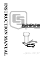
385 Met One Rain and Snow Gage .........................................................1
Typical Snow Gage Installation ..............................................................4
Pedestal Base Options .............................................................................5
Connecting Signal Cable Leads ..............................................................6
Remove Screen if Snow is Anticipated ...................................................7
Connecting Heater Wires ........................................................................8
i
Met One Rain Gage Table of Contents
Tables
4-1. Wiring for Pulse Channel Input.............................................................. 9
4-2. Wiring for Control Port Input................................................................. 9
7-1. Volume of Water for Recalibration ...................................................... 15
ii
Met One Rain Gage Models 380 and 385
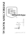
1. Introduction
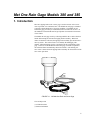
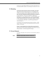
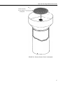
Met One's tipping bucket rain or snow gage is used to measure rain or snow
water equivalent on a continuous basis. The Model 380 rain gage is intended
to measure rainfall during above freezing conditions. The Model 385 AC
heated rain gage provides year round measurement of either rain or snow. In
the standard versions Model 380/385, precipitation is measured in increments
of 0.01 inches.
The Model 380 rain gage works by collecting rainfall in the 12 inch collection
funnel and metering the rain into the tipping bucket assembly. When 0.01
inches of rainfall are collected, the tipping bucket assembly tips and activates a
mercury switch. The switch closure is recorded by the datalogger pulse
channel. When the bucket tips, the water drains out the screened base of the
gage. In the case of the Model 385 heated rain gage, snowfall is captured in
the collection funnel and melted by the heater element. After melting, the
snow water is metered into the tipping bucket assembly for measurement of the
snow water equivalent.
FIGURE 1-1. 385 Met One Rain and Snow Gage
The 385 ships with:
(1) Calibration Sheet
(1) Instruction Manual
1
Met One Rain Gage Models 380 and 385
2. Specifications
MODEL 380/385 RAIN GAGE
Funnel:
12 inch (30.5 cm)
Accuracy:
±0.5% < 0.5"(1.27 cm)/hr rate
±2.0% < 3.0"(7.62 cm)/hr rate
Resolution:
380/385
0.01 inch
Environmental Conditions:
Temperature:
0°C to +50°C
Humidity:
0 to 100%
Dimensions:
Weight:
Height:
Diameter:
7 pounds (3.2 kg) w/ 50 ft. signal cable
14" (35.5 cm)
12" (30.5 cm)
MODEL 385
Specifications same as Model 380 unless listed below.
Environmental Conditions:
Temperature:
-20°C to +50°C
Humidity:
0 to 100%
Weight:
12.2 pounds (5.57 kg) w/ 50' power/signal cable
Heater Power Specification:
Voltage:
115 VAC (50/60 Hz)
Current:
5 amps maximum
Heater:
300 W Cartridge Element
NOTE
The black outer jacket of the cable is Santoprene® rubber. This
compound was chosen for its resistance to temperature extremes,
moisture, and UV degradation. However, this jacket will
support combustion in air. It is rated as slow burning when
tested according to U.L. 94 H.B. and will pass FMVSS302.
Local fire codes may preclude its use inside buildings.
3. Installation
3.1 Siting
The rain or snow gage should be mounted in a relatively level spot which is
representative of the surrounding area. The lip of the funnel should be
horizontal and at least 30 inches above the ground. Install the snow gage high
enough to prevent burial by snow during the winter months. The ground
surface around the rain gage should be natural vegetation or gravel. The gage
should not be installed over a paved or concrete surface. Refer to Figure 3-1
for an illustration of gage installation.
2
Met One Rain Gage Models 380 and 385
The rain or snow gage should be placed away from objects that obstruct wind.
The minimum distance should be 2 times the height of the obstruction or more.
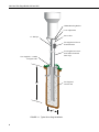
3.2 Mounting
The rain or snow gage is designed to mount on a flat surface. Three equally
spaced adjustable mounting legs are provided. The mounting legs are predrilled for 1/4" bolts on a 9.66" diameter bolt circle. A mounting bracket is
available from Campbell Scientific (CM240) to install either the rain or snow
gage. The mounting bracket provides additional adjustment for leveling the
rain or snow gage. The CM240 base helps level the rain gage, ensuring a more
accurate measurement. The base may be attached to a CM300-Series
Mounting Pole or to a user-supplied 1.5 IPS (1.9” OD, unthreaded) pipe. The
pipe should be long enough to place the gage's orifice at a one-meter height.
The pole or pipe can be placed directly into a concrete foundation, attached to
a concrete foundation using J-bolts, or self-supporting with legs (see Figure 32). A concrete pad is recommended. A typical snow gage installation is
illustrated in Figure 3-1.
Loosen the three screws and lift the housing assembly from the base. Adjust
the three slotted feet on the base of the rain gage and/or the three nuts on the
CM240 to level the gage.
Remove the rubber shipping band securing the stainless steel tipping bucket
assembly. Verify the bucket tips freely and that all the adjusting screws are
tight. Replace the housing assembly and tighten the three screws to secure the
housing to the base. Level the rain gage after mounting it.
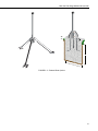
3.3 Screen Removal
If snowfall is anticipated, remove the primary screen from funnel, as shown in
Figure 3-3.
NOTE
Remember to replace primary screen after a snowfall event.
3
Met One Rain Gage Models 380 and 385
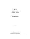
CM240 Mounting Bracket
Level Adjustments
Power Cable
1.5” IPS Pipe
User-Supplied AC Power
Termination Box
User-Supplied AC Power
and Conduit for Heated
Snow Gage
User-Supplied 1” Conduit
for Signal Cable
User-Supplied
Concrete Pad
24”
8”
FIGURE 3-1. Typical Snow Gage Installation
4
Met One Rain Gage Models 380 and 385
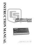
3.5”
1.5”
24”
14”
FIGURE 3-2. Pedestal Base Options
5
Met One Rain Gage Models 380 and 385
P/N 2196 (2) Plcs.
6”
WHITE
3/8”
8”
Cut Shield Off Flush to Jacket
3/8”
WHITE
SHIELD
BLACK
Clear Heat Shrink
BLACK
Heat Shrink (2) Plcs.
P/N 9661
2”
8”
3/8”
3/8”
BLACK
WHITE
GREEN
Heat Shrink (2) Plcs.
P/N 7805 Beldon #1934B
ATTACH WHITE OF (SIGNAL CABLE) TO PIN 3
FIGURE 3-3. Connecting Signal Cable Leads
6
Met One Rain Gage Models 380 and 385
Remove Primary
Screen if Snow is
Anticipated
FIGURE 3-4. Remove Screen if Snow is Anticipated
7
Met One Rain Gage Models 380 and 385
$
$
#
"
!
%% &' () *
+
%'$ , "
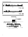
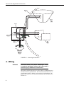
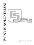
FIGURE 3-5. Connecting Heater Wires
4. Wiring
WARNING
Disconnect heater power before attempting to service
or repair this equipment. Failure to do so may result in
personal injury or death due to electrocution.
The BLACK (Signal) lead connects to a pulse channel. The WHITE (Power
Ground) connects to ground channel. The CLEAR (shield) lead connects to
ground channel. Refer to Table 4-1 for the wiring of your datalogger. The
purpose of the shield wire is to drain any charges built up in the cable due to
transients etc.
8
Met One Rain Gage Models 380 and 385
4.1 Heater Wiring
Attach the power plug supplied with the Model 385 by following the
instructions supplied with the plug. The electric heated snow gage requires
115VAC (50/60hz), 5 amps maximum, to operate the heater. (If supplying
your own signal or power cable, refer to Figure 3-4 for an illustration of cable
installation.) The heater should be unplugged during warmer months to
prevent evaporation during low rainfall and to minimize wear and tear on the
heater element.
NOTE
The heater thermostat is factory set and requires no field
adjustment.
4.2 Wiring for Pulse Channel Input
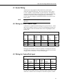
Connections to Campbell Scientific dataloggers are given in Table 4-1. When
Short Cut for Windows software is used to create the datalogger program, the
sensor should be wired to the channels shown on the wiring diagram created
by Short Cut.
TABLE 4-1. Wiring for Pulse Channel Input
Color
Description
CR800
CR1000
CR3000
CR5000
Black
Signal
Pulse Channel Pulse Channel Pulse Channel P_SW
White
Signal Return
G
Clear
Shield
G
CR500
CR510,
CR10(X),
21X,
CR7,
CR23X
CR200
Series
Dataloggers listed in Table 4-2 have the capability of counting switch closures
on some of their control ports. When a control port is used, the return from the
rain gage must be connected to +5 volts on the datalogger.
4.3 Wiring for Control Port Input
TABLE 4-2. Wiring for Control Port Input
Color
Description
CR800
CR1000
CR3000
Black
Signal
Control Port C2/P3
White
Signal Return 5 V
Clear
Shield
CR500,
CR510
5V
CR10(X)
CR23X
Control Port Control Port
5V
5V
G
The CR10 does not support the use of control port inputs with the Pulse Count
instruction; use Short Cut or see Example 8.5 in the CR10 operator’s manual.
9
Met One Rain Gage Models 380 and 385
5. Datalogger Programming
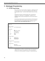
5.1 CR10X Programming
This section is for users who write their own programs. A datalogger program
to measure this sensor can be created using Campbell Scientific’s Short Cut
Program Builder software. You do not need to read this section to use Short
Cut.
The Model 385 rain gage is measured using the Pulse Count instruction
configured for a switch closure. In all dataloggers, a multiplier of 0.01
converts the output to inches and a multiplier of 0.254 converts the output to
millimeters.
The following example program uses a pulse channel to read the output from
the rain gage and will work with CR500, CR510, CR10(X), 21X or CR23X.
The CR7 is similar but has an additional parameter in the Pulse Count
instruction to specify the slot that the Pulse Card is in.
Input Location Labels:
1. Rain (in)
*Table 1 Program
01: 10
Sec. Execution Interval
1: Pulse (P3)
1: 1
2: 1
3: 2
4: 1
5: 0.01
6: 0
Rep
Pulse Input Channel
Switch Closure
Loc [:Rain (in)]
Mult
Offset
2: If time is (P92)
1: 0
minutes into a
2: 60
minute interval
3: 10
Set high Flag 0
3: Real Time (P77)
1: 110
Day,Hour-Minute
4: Totalize (P72)
1: 1
2: 1
Repetitions
Starting Input Location
5: End Table 1
Output Instruction 72, Totalize, is used in the output section of the program to
output the total rainfall over the output interval. This section should be
executed every scan and not placed in a subroutine or conditional statement.
10
Met One Rain Gage Models 380 and 385
5.1.1 CR200 Series Programming
'CR200 Series
'Example program showing measurement of a 380/385 sensor every 10 seconds.
'Declare Public Variables and Units
Public Rain_in
Units Rain_in=inch
'Define Data Tables
DataTable(Table1,True,-1)
DataInterval(0,60,Min)
Totalize(1,Rain_in,False)
EndTable
'As an example store the data every 60 minutes.
'Main Program
BeginProg
Scan(10,Sec)
'MetOne 380/385 Rain Gauge measurement Rain_in:
PulseCount(Rain_in,P_SW,2,0,0.01,0)
'Call Data Tables and Store Data
CallTable(Table1)
NextScan
EndProg
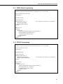
5.1.2 CR1000 Programming
‘CR1000
‘Example program showing measurement of a 380/385 sensor every 10 seconds.
‘Declare Variables and Units
Public Rain_in
Units Rain_in=inch
‘Define Data Tables
DataTable (Table1,True,-1)
DataInterval (0,60,Min,10)
Totalize (1,Rain_in,FP2,False)
EndTable
‘As an example store the data every 60 minutes.
‘Main Program
Begin Prog
Scan (10,Sec,1,0)
‘MetOne 380/385 Rain Gauge measurement Rain_in:
PulseCount (Rain_in,1,1,2,0,0.01,0)
‘Call Data Tables and Store Data
CallTable (Table1)
NextScan
End Prog
11
Met One Rain Gage Models 380 and 385
‘Main Program
BeginProg
Scan(10,Sec,1,0)
‘Default Datalogger Battery Voltage measurement Batt_Volt:
Battery(Batt_Volt)
‘MetOne 380/385 Rain Gauge measurement Rain_in:
PulseCount(Rain_in,1,1,2,0,0.01,0)
‘Call Data Tables and Store Data
CallTable(Table1)
CallTable(Table2)
NextScan
EndProg
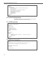
5.2 Control Port Programming
The following examples measure a 380 and 385 rain gage using a control port
on a datalogger. Wire the sensor as shown in Table 4-2.
5.2.1 CR1000 Programming
'CR1000
'Declare Public Variables and Units
Public Rain_in
Units Rain_in=inch
DataTable (Rain,True,-1)
DataInterval (0,60,Min,0)
Totalize (1,Rain_in,FP2,0)
EndTable
'Main Program
BeginProg
Scan (1,Sec,1,0)
PulseCount (Rain_in,1,18,2,0,.01,0)
CallTable (Rain)
NextScan
EndProg
; Black wire connect to C8
5.2.2 CR200 Series Programming
'CR200
'A 20 kOhm pull up resistor is required to read a switch closure on C1 or C2
'as a Pulse Counter. The 20 kOhm resistor uses the battery voltage.
'Declare Public Variables and Units
Public Rain_in
Units Rain_in=inch
12
Met One Rain Gage Models 380 and 385
'Define Data Tables
DataTable(Table1,True,-1)
DataInterval(0,60,Min)
Totalize(1,Rain_in,False)
EndTable
'As an example store the data every 60 minutes.
'Main Program
BeginProg
Scan(10,Sec)
'MetOne 380/385 Rain Gauge measurement Rain_in:
PulseCount(Rain_in,C2,2,0,0.01,0)
; Black wire connect to C2
'Call Data Tables and Store Data
CallTable(Table1)
NextScan
EndProg
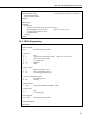
5.2.3 CR10X Programming
;{CR10X}
;
*Table 1 Program
01: 1
Execution Interval (seconds)
1: Pulse (P3)
1: 1
2: 8
3: 2
4: 1
5: .01
6: 0
Reps
Control Port 8 (switch closure only) ; Black wire connect to C8
Switch Closure, All Counts
Loc [ Rain_inch ]
Multiplier
Offset
2: If time is (P92)
1: 0
Minutes (Seconds --) into a
2: 60
Interval (same units as above)
3: 10
Set Output Flag High (Flag 0)
3: Set Active Storage Area (P80)
1: 1
Final Storage Area 1
2: 101
Array ID
4: Real Time (P77)
1: 1220
Year,Day,Hour/Minute (midnight = 2400)
5: Totalize (P72)
1: 1
2: 1
Reps
Loc [ Rain_inch ]
*Table 2 Program
02: 0.0000
Execution Interval (seconds)
*Table 3 Subroutines
End Program
13
Met One Rain Gage Models 380 and 385
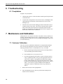
6. Troubleshooting
6.1 Precipitation
Symptom: No precipitation
1.
Check that the sensor is wired to the Pulse Channel specified by the Pulse
Count instruction.
2.
Verify that the Configuration Code (Switch Closure), and Multiplier and
Offset parameters for the Pulse Count instruction are correct for the
datalogger type.
3.
Disconnect the sensor from the datalogger and use an ohm meter to do a
continuity check of the switch. The resistance measured at the terminal
block on the inside of the bucket between the black and white leads
should vary from infinite (switch open) when the bucket is tipped, to less
than an ohm when the bucket is balanced.
7. Maintenance and Calibration
During each site visit, check for and remove any debris, insects, sediment, etc.
from the collection funnel, debris screens, or tipping bucket assembly. Verify
the tipping bucket assembly moves freely, and that the datalogger records 0.01
in for each bucket tip.
7.1 Customer Calibration
The sensor is factory calibrated; recalibration is not required unless damage
has occurred or the adjustment screws have loosened. Nevertheless, the
following calibration check is recommended once every 12 months:
14
a.
Remove the housing assembly from the base by loosening the three
screws and lifting upward on the housing.
b.
Check bubble level to verify sensor is level.
c.
Pour water through the inner funnel to wet the two bucket surfaces.
Using a graduated cylinder, slowly pour the appropriate amount of
water (refer to Table 7-1) through the inner funnel to the tipping
bucket, which should tip once. Repeat for the other bucket. If both
buckets tip when filled with the appropriate amount of water (refer to
Table 7-1), the sensor is properly calibrated and no additional
adjustment is needed. If either bucket fails to tip, recalibrate as
follows:
1.
Release the lock nuts on the cup adjustments.
2.
Move the adjustment screws down to a position that would place the
bucket far out of calibration.
Met One Rain Gage Models 380 and 385
3.
Pour the appropriate amount of water (see Table 7-1) into the inner funnel
(i.e. 18.52 ml for 0.01 inches of rain / tip):
Conversion Factors:
113.04 in2 (catch orifice area) x increment in inches.
Tip to in3:
3
multiply by 16.3881.
in to ml:
ml to ounces:
multiply by 0.03382.
4.
Turn the cup adjustment screw, opposite the full bucket, up until the
bucket assembly tips. Tighten the lock nut.
5.
Repeat steps 3 and 4 for the opposite bucket.
6.
Repeat steps 1-5 to ensure proper calibration.
7.
Reinstall the housing assembly and tighten the three screws.
TABLE 7-1. Volume of Water
for Recalibration
Tip Increment
in3
ml
ounces
0.01 in
1.130
18.52
0.63
7.2 Factory Recalibration
Factory recalibration is available from either Campbell Scientific Incorporated
or Met One Instruments. Please call and request an RMA number prior to
returning any equipment to Campbell Scientific Incorporated
15
Met One Rain Gage Models 380 and 385
16
This is a blank page.
Campbell Scientific Companies
Campbell Scientific, Inc. (CSI)
815 West 1800 North
Logan, Utah 84321
UNITED STATES
www.campbellsci.com
[email protected]
Campbell Scientific Africa Pty. Ltd. (CSAf)
PO Box 2450
Somerset West 7129
SOUTH AFRICA
www.csafrica.co.za
[email protected]
Campbell Scientific Australia Pty. Ltd. (CSA)
PO Box 444
Thuringowa Central
QLD 4812 AUSTRALIA
www.campbellsci.com.au
[email protected]
Campbell Scientific do Brazil Ltda. (CSB)
Rua Luisa Crapsi Orsi, 15 Butantã
CEP: 005543-000 São Paulo SP BRAZIL
www.campbellsci.com.br
[email protected]
Campbell Scientific Canada Corp. (CSC)
11564 - 149th Street NW
Edmonton, Alberta T5M 1W7
CANADA
www.campbellsci.ca
[email protected]
Campbell Scientific Ltd. (CSL)
Campbell Park
80 Hathern Road
Shepshed, Loughborough LE12 9GX
UNITED KINGDOM
www.campbellsci.co.uk
[email protected]
Campbell Scientific Ltd. (France)
Miniparc du Verger - Bat. H
1, rue de Terre Neuve - Les Ulis
91967 COURTABOEUF CEDEX
FRANCE
www.campbellsci.fr
[email protected]
Campbell Scientific Spain, S. L.
Psg. Font 14, local 8
08013 Barcelona
SPAIN
www.campbellsci.es
[email protected]
Please visit www.campbellsci.com to obtain contact information for your local US or International representative.