1
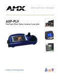
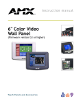
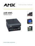
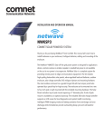
Quick Start Guide
ViewPoint Wireless Touch Panels (Firmware version G3)
For more detailed installation, configuration, programming, and operating
instructions, refer to the ViewPoint Wireless Touch Panels Instruction
Manual available on-line at www.amx.com.
Specifications
Overview
Power:
The ViewPoint Wireless Touch Panels and ViewPoint NetWave Touch Panels are
hand-held touch panels that allow you to control devices remotely via either IR or
RF. The TPDesign3 software application is used to design the panel pages. Onscreen buttons provide control over external devices. TPDesign3 is available for
download via www.amx.com.
Models:
VPT-CP One-way RF (FG5964-418)
VPN-CP Two-way NetWave (FG5964-02)
VPN-CP/EU Two-way NetWave - EU compliant (FG5964-12)
Power Consumption
1.3 A @ 13.5 VDC
VPA-BP (battery)
• 7.2 VDC, 6-cell NiMH (nickel metal hydride) rechargeable battery,
3.7 Ah minimum. Provides five continuous hours of use, with full
back lighting.
Power supply
Dimensions (HWD)
• 2.8 A @ 12 VDC
5.99" x 8.75" x 2.78" (15.21 cm x 11.30 cm x 5.08 cm)
Weight:
The ViewPoint Touch Panels are available with either one-way RF (VPT-CP) or
two-way digital spread-spectrum wireless control (VPN-CP).
The VPN-CP/EU offers EU-compliant two-way digital spread-spectrum wireless
control.
Note: Two-way ViewPoints do not support AMX IR codes (38 KHz and 455 KHz)
but do support other manufacturers IR codes. One-way ViewPoints support all IR
codes.
Viewpoints utilize a 6”, color-passive, 256 color LCD (liquid crystal display). They
have programmable firmware that can be upgraded via the Programming port.
Viewpoints also feature four programmable external pushbuttons that can be
used to provide level control (for use with channels, volume, and lighting).
VPT-CP
• 2.46 lbs. (1.11 kg) with battery, 1.97 lbs. (0.89 kg) without battery
VPN-CP , VPN-CP/EU
• 2.48 lbs. (1.12 kg) with battery, 2.01 lbs. (0.91 kg) without battery
Operating Frequency:
RF (VPT-CP)
• 418 MHz standard (other frequencies available upon request),
one-way RF transmission
IR (VPT-CP)
• 38 KHz or 455 KHz, one-way IR transmission
RF (VPN-CP, VPN-CP/EU)
• 2.4 GHz two-way digital spread spectrum, two-way digital spread
spectrum RF or one-way OM (other manufacturer’s) IR signals
Buttons:
Four external programmable push buttons
Screen Resolution (HV):
6" (153.9 mm) color-passive LCD, 256 colors - 320 x 240 (HV) pixels
Assignable Devices:
VPT-CP
FIG. 1 shows the orientation of the external jacks and programmable external
buttons.
ViewPoint RF
• Device 1
AMX IR
• Device 1
IR other than AMX’s
• Device 2, 3, and/or 4
VPN-CP, VPN-CP/EU
Programmable
buttons
Programming
port
Programmable
buttons
Power jack
Device ID
• 0 - 255
Group ID
• 0 - 15
ViewPoint
• Device 1, 2, 3, and/or 4
IR
• Device 2, 3, and/or 4
Cables:
External power cable
• 6 mm coax male power cable - connects from an external 13.5
VDC power supply (included)
Programming cable
• 3-wire, 2.5 mm stereo conductor cable
Connector Ports:
External power
Programming
FIG. 1 ViewPoint Wireless Touch Panel
Memory:
IR files
Note: Panel programming, pages, and buttons are sent and received to/from the
panel via the TPDesign3 Touch Panel Design software application. TPDesign3
can also convert G2 panel pages into G3 firmware compatible pages. Refer to
the TPDesign3 Touch Panel Design Program Instruction Manual (also available
online).
Multiple ViewPoints in an Installation
ViewPoints transmit data via either RF or IR. The VPT-CP (one-way) ViewPoints
ship configured to operate on a standard frequency of 418 MHz RF, and
user-selectable (38 KHz or 455 KHz) IR frequencies. One-way ViewPoints can
be ordered for different RF operating frequencies that must be set when the unit
is manufactured.
If you plan to use multiple one-way ViewPoints within the same area, it is strongly
recommended that each unit be ordered for operation on different RF
frequencies. This will prevent erroneous data being received by the respective
Controller.
The VPN-CP and VPN-CP/EU (two-way) ViewPoints operate on 2.4 GHz for
two-way RF communications with the AXR-NWS (or AXR-NWS/EU) NetWave
Server. It also provides one-way IR using other manufacturers IR codes. Refer to
the AXR-NWS NetWave Server instruction manual for more information.
Caution: To satisfy FCC RF Exposure requirements for mobile and base station
transmitting devices, a separation distance of 32 cm or more should be
maintained between the antenna of this device and persons during operation. To
ensure compliance, operation at closer than this distance is not recommended.
Note: The 2-way Viewpoint communication uses frequencies from 2.402 GHz to
2.478 GHz in 1 MHz steps. This results in 76 possible frequencies. All 16 Group
IDs utilize all 76 frequencies. Changing Group IDs basically changes the
hopping pattern sequence.
• 6 mm coax female power jack - connects to external 13.5 VDC
power supply
• 2.5 mm stereo female conductor jack
• 512 KB of SRAM and 2 MB of flash for a total of 2.5 MB
• 16 KB
Buttons
• 225 KB
Bitmaps
• 1245 KB
Icons
• 262 KB
Fonts
• 262 KB
Operating Temperature:
Indoor operation at temperatures between 0º C (32º F) to 40º C
(104º F)
Operating Humidity:
5% to 90% RH (non-condensing)
Enclosure:
High impact molded plastic, matte black finish
Included Accessories:
VPA-BP
• ViewPoint Rechargeable Battery
Power supply
• 13.5 VDC, PS 2.8 A power supply
Programming Cable
• 2.5 mm stereo to male DB-9 (FG10-817)
Optional Accessories:
VPA-BP
• Additional ViewPoint Rechargeable Battery (FG0962)
AXR-RF
• RF Receiver (VPT-CP only) (FG782-418)
AXR-NWS
• NetWave Server (VPN-CP only) (FG5930-02)
AXR-NWS/EU
• NetWave Server (VPN-CP/EU only)(FG5930-12)
VPA-DS
• ViewPort Docking Station (FG5961-02)
Extension cable
• DB-9 extension cable (female DB-9 to female DB-9) (FG10-727)
Using Connector Ports
All ViewPoints have two connectors (FIG. 2). The power jack is for connecting an
external 12 VDC power supply for ViewPoint operation and charging. The
programming jack is used for communication between the ViewPoint touch panel
and TPDesign3. The programming jack uses a three-wire, 2.5 mm stereo jack.
The required cable and power supply comes furnished with the ViewPoint.
To connect and configure the ViewPoint for file transfers:
1.
Connect the 2.5 mm stereo plug (male) end of the programming cable
(FG10-817) into the programming jack on the side of the ViewPoint.
the ViewPoint. AMX strongly recommends that you use only AMX (VPA-BP)
rechargable Packs.
Activating Edit Mode
Power
jack
Programming
jack
Stereo
plug
male
DB-9 connector
ViewPoint
to PC
programming
cable
Connect FG10-817 to cable FG10-727
FIG. 2 ViewPoint connectors
2.
When powering up the touch panel, the first page is the Main page. Before
designing touch panel pages and buttons, you must activate Edit mode. Once
activated, use the EDIT button to access Edit bar. This mode has options to
add and configure touch panels and buttons.
1.
Press SETUP in the Main page to open the Setup page (FIG. 3).
2.
Press PROTECTED SETUP to open the keypad.
3.
Enter 1988 (default password) in the keypad and press ENTER to open
Protected Setup page. If you press ENTER after typing an incorrect password, you are immediately returned to the previous page.
4.
Press EDITOR to enable Edit mode. The EDITOR button is highlighted in
the Protected Setup page when enabled, as shown in FIG. 4.
Connect the DB-9 end of the programming cable to the female DB-9
connector on the DB-9 extension cable (FG10-727).
Connect the female DB-9 terminal end of the extension cable to the port
on the back of your computer (FIG. 2) and configure the communication
parameters in TPDesign3.
3.
Refer to the TPDesign3 Instruction Manual for details on performing file transfer
operations.
VPA-DS ViewPort Docking Station (Optional Accessory)
The ViewPort Docking Station includes a built-in battery charger and an angled
desktop docking station to cradle your ViewPoint touch panel.
VPA-DS Specifications
Dimensions (HWD)
5.
6.
4.83" x 8.26" x 7.62" (122.7 mm x 209.8 mm x 193.4 mm)
Environmental operating range:
Temperature
• 50 °F to 104 °F (10 °C to 40 °C)
Humidity
• 0% to 90% non-condensing
Power
FIG. 3 Setup page
7.
FIG. 4 Protected Setup page
Press EXIT to close the Protected Setup page and return to the Setup
page (now in Edit mode).
Press EXIT again to return to the Main page. The EDIT button appears at
the top of the page indicating Edit mode is active.
Press EDIT to open the Edit bar. The BUTTON and PAGE options in the
Edit bar are used to design and modify button and page settings.
2.8 A @ 12 VDC
Setting the Device Base
Yellow LED
• Indicates ViewPoint connected to ViewPort Docking Station
Green LED
• Indicates spare battery is fully charged
Press the DEVICE BASE option in the Protected Setup page to assign a base
(starting) device address to the touch panel.
Red LED
• Indicates spare battery is charging
Indicators:
1.
Options:
Power supply
• 2.8 A @ 12 VDC power supply
Battery
• VPA-BP ViewPoint Rechargeable Battery
(NiMH, 3.7 Amp @ 7.2 VDC)
2.
Utilizing the on-screen keypad, enter the base address for the touch
panel. The base address range is from 1 - 255. Standard device
addresses begin at 128.
Press ENTER to save the value.
Setting the Device Used
Recharging the Battery
Units are shipped with batteries needing to be charged. The battery
(VPA-BP) can be recharged by connecting the 12 VDC power supply to the
power jack on the side of the ViewPoint (FIG. 1). The battery can also be
charged on the optional ViewPort docking station (VPA-DS).
Power to charge the battery is supplied to the optional VPA-DS when the power
supply is plugged into the rear power connector on the docking station. A
ViewPoint battery can be charged in three different ways:
Use the DEVICE USED option in the Protected Setup page to assign a value
for the number of devices being controlled by the touch panel.
1.
2.
Press DEVICE USED to open the keypad and enter the panel’s device
number from 1 - 4. Each device number supports up to 255
programmable channel codes. The multiple device settings allow you to
create up to four unique touch panel buttons and/or pages. This value is
used to determine the current device being used by the panel.
Enter the number of devices being used by the touch panel.
3.
Press ENTER to save the value.
•
An external power supply can be plugged into the side of the ViewPoint to
supply power to the panel and the on-board battery charger.
•
The ViewPoint can be placed onto an optional ViewPort Docking Station
VPA-DS that will supply external power to run the panel and the on-board
battery charger.
Serial Commands
Without the VPN on the station the ViewPoint battery can be removed
from the ViewPoint and placed into the battery compartment of the
optional ViewPort Docking Station.
panel calibration.
•
After installing the battery pack you must apply power and allow to charge for 5
hours in order to reach optimal charge. You may also charge the battery using
a Viewport Docking Station (an optional. The ViewPort has a self-contained
smart-chip that reads the power level of the battery and then performs a
"smart-charge" based on the amount of power and duration needed for the best
possible charge per session.
Note: The ViewPort allows simultaneous charging of both the installed battery
and a mounted ViewPoint panel (assuming the use of a PSN2.8 power supply).
The red LED does not turn Off when the ViewPoint is attached because the
ViewPort is still charging the installed battery and is still supplying voltage to
CALIBRATE Syntax:
"CALIBRATE"
Starts touch
Example:
CALIBRATE
Starts the calibration sequence mode on the touch panel.
SETUP
Syntax:
Puts the touch
panel on the
Setup Page.
Example:
"SETUP"
SETUP
Flips the touch panel to the Setup page.
ZAP!
Syntax:
Clears all
memory.
Example:
"ZAP!"
ZAP!
Clears all memory and erases all buttons, pages, drawings, and symbols.
AMX Corporation reserves the right to alter specifications without notice at any time.
For full warranty information, refer to the AMX Instruction Manual(s) associated with your Product(s).
036-004-2666 10/04 ©2004
AMX Corporation. All rights reserved. The AMX logo is a trademark of AMX Corporation. AMX reserves the right to alter specifications without notice at any time.
3000 RESEARCH DRIVE, RICHARDSON, TX 75082 • 800.222.0193 • fax 469.624.7153 • technical support 800.932.6993 • www.amx.com
93-5963
REV: C