1
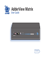
AdderView Matrix
User Guide
Mounting ....................................................................................5
Connections .................................................................................5
User port connections.............................................................6
Computer port connections to standard computers ............6
Computer port connections to alternative computers .........7
Connections to a Sun® computer .....................................7
Connections to a USB port.................................................8
Power supply connection .......................................................9
AdderLink IP connections.....................................................10
Power switching connections...............................................11
Cascade connections.............................................................12
How cascade connections operate..................................13
Addressing computers in a cascade ................................14
Using cascaded computers...............................................15
Testing specific links to cascaded computers..................15
Multiple video head connections ........................................16
Installation
Overall initial configuration ....................................................17
Configuration menus ................................................................18
Configuration menus layout ................................................19
Registering users...................................................................20
Registering computers..........................................................20
Autoscanning ........................................................................21
Saving and restoring configuration settings.......................22
Preparations for configuration save/load ......................22
What to do if the ADMIN password has been forgotten...23
Ensuring that the serial port is available for other functions23
Hot plugging and mouse restoration ..................................24
Which restore setting do I use?.......................................24
Resetting user port keyboards and mice .............................25
Disabling mouse acceleration ..............................................25
Power switching configuration............................................26
Editing power strings.......................................................27
Creating power port groups............................................27
Logging access activity .........................................................28
Display Data Channel (DDC).................................................28
Adder Port Direct..................................................................29
Introduction .................................................................................3
What’s in the box ........................................................................4
What you may additionally need ...............................................4
Configuration
Welcome
Contents
Contents - page 2
1
Index
Troubleshooting ........................................................................36
Getting assistance......................................................................36
Appendices ................................................................................37
Appendix 1 – Configuration menu items ............................37
Setup Options...................................................................37
Global Preferences ...........................................................38
User Preferences...............................................................40
Advanced Options............................................................42
Appendix 2 – Firmware upgrade .........................................43
Appendix 3 – Cable and connector specifications ..............45
RS232 serial mouse to PS/2 converter cable ...................45
RS232 serial flash upgrade cable.....................................45
RS232 serial synchronisation cable..................................45
AdderView Matrix to power switch cable .....................46
Power switch to power switch daisy chain cable ...........46
AdderView Matrix setup cable .......................................46
Other products in the Adder range..........................................47
Safety information ....................................................................47
Warranty ....................................................................................47
Radio Frequency Energy ...........................................................48
Powering on ..............................................................................30
The front panel controls ...........................................................30
Using the AdderView Matrix ....................................................31
Selecting a computer............................................................31
Logging in and out ..........................................................33
Selecting cascaded computers .............................................34
The confirmation box ...........................................................34
The reminder banner............................................................34
Routing status .......................................................................35
User preferences and functions ...........................................35
Using power switching .........................................................35
Further information
Operation
2
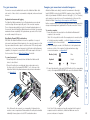
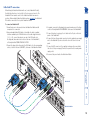
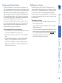
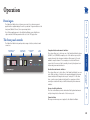
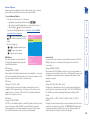
Optional network/Internet remote control
The optional AdderLink IP allows direct
connection to an Ethernet-based local
network and from there onto the wider
Internet, as required. The robust AdderLink
IP security system will also allow direct
connection to the Internet. A second
AdderLink IP can be added to the other
user port to provide even greater remote
connectivity. The AdderLink IP also provides a
local user connection port.
User
1
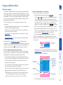
Thank you for choosing the AdderView Matrix from
Adder Technology. This advanced switch (available in
two sizes) allows you to control multiple host computers
directly, or far more computers in combination with other
similar switches. Two users can simultaneously access
any connected host computers. With the addition of the
optional AdderLink IP unit, the user(s) can be situated
anywhere via the internet.
In common with other Adder advanced switches, the
AdderView Matrix and AdderLink IP both support
the Adder Port Direct format. This messaging
system allows the interconnected switches to declare
between themselves the locations and requirements
of their respective host computers. This greatly eases
configuration and simplifies host computer selection.
User
2
OR
AdderView Matrix
Power switch
LOC
REM VNC
100
LNK PWR
AdderLink IP
User
1
IP network/
Internet
Other KVM
switches
Control of many hosts
On its own, the AdderView
Matrix provides access to
either eight (model AVM208)
or sixteen (model AVM216)
host systems. However,
when linked to other KVM
switches (AdderView Matrix
or otherwise) the user(s)
can easily control up to 128
separate host systems.
Host
systems
Optional power control
AdderView Matrix
provides the opportunity
to attach one or more
power switches. These
control the supply to the
host system(s) and allow
the remote user to hard
reset any system that has
suffered a failure.
Introduction
User
1
Dual users
AdderView Matrix allows control
of the host systems by two directly
connected keyboard/video/mouse
sets. Alternatively, an AdderLink
IP can be connected instead to
provide remote control options.
Welcome
3
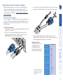
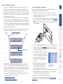
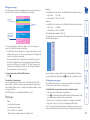
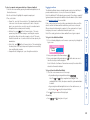
What’s in the box
What you may additionally need
Power supply
and countryspecific power
lead
Six self-adhesive
rubber feet
CCSUN converter
Required to connect Sun computers
that use a mini-DIN port to connect
their keyboard and mouse
Part number: CCSUN-xM
(where x is the cable length in metres:
2, 5 or 10)
Master power switch for connection to
AdderView Matrix or standalone Ethernet
operation (part number: PSU-8MASTER)
Slave power switches for connection
to AdderView Matrix or master power
switch (part number: PSU-8SLAVE)
PS/2 to AT-style keyboard converter
(part number: VSA3)
PS/2 to 9-pin serial mouse converter
(part number: VSA1)
CD-ROM
CCUSB converter
Required to connect with computers
that use a USB port to connect their
keyboard and mouse
Part number: CCUSB-xM
(where x is the cable length in metres:
2, 5 or 10)
AdderView Matrix
(model AVM216 shown)
KVM cables
One set per connected computer
Part number: VKVM-xM
(where x is the cable length in
metres: 1, 2, 5 or 10)
Serial flash upgrade cable
(part number: CAB-9M/9F-2M)
AVM208 rack brackets
Includes four screws
Part number: RMK1
AVM216 rack brackets
Includes six screws
Part number: RMK2
4
Installation
To attach the rack-mount brackets
1 On either side of the AdderView Matrix casing, position a rack mount
bracket with the slotted
holes facing out from
the front of the unit.
2 Secure the bracket with
three of the supplied
screws.
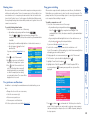
Installation of the AdderView Matrix involves numerous connections, which can
be classified into the following basic groups:
• User port connections
• Computer port connections to standard computers
• Computer port connections to alternative computers
• Power supply connection
There are also connections that can be made to achieve more advanced
configurations:
• AdderLink IP connections
• Power switching connections
• Cascade connections
• Multiple head video connections
Connections
The initial step is to mount the AdderView Matrix in an optimum position,
where:
• It is in close proximity to the various computers that will be connected to it.
• There is a power supply socket.
• Optionally, there is an Category 5e or 6 network connection, if the
AdderLink IP is also being used.
The AdderView Matrix can be used on a desktop or mounted within a 19” rack.
For desktop applications, attach the supplied self-adhesive feet to the underside
to avoid damage to the desktop surface. For rack-mount applications, use the
optional brackets and mount the unit within the frame before connecting any
cables.
Mounting
This chapter covers the physical mounting and connection of the AdderView
Matrix.
AdderView Matrix AVM216
AdderView Matrix AVM208
5
Data Display Channel (DDC) considerations
DDC allows the AdderView Matrix to discover the capabilities of a user port
video monitor and transmit that information to the connected computers so that
they can moderate their video output to suit the monitor. DDC can only sample
one monitor, so if you are connecting monitors of different resolution/frequency
capabilities, it is important to ensure that the DCC feature samples the lesser of
the two monitors. Please see Display Data Channel for details.
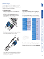
Monitor (video)
Blue
Keyboard
Purple
Mouse
or
Mid green
To connect a computer
1 Ensure that power is disconnected from the AdderView Matrix and all
computers to be connected.
(Note: If it is not possible to switch off a computer prior to connection, then
a ‘Hot plug’ procedure is available – see the Hot plugging and mouse
restoration section for more details).
2 Connect the plugs at one end of a KVM cable set to the keyboard, video
and mouse sockets of the computer (for keyboard and mouse plug
conversion information – see Appendix 3).
3 Connect the plugs at the other end of the KVM cable set to the corresponding
sockets, of the required COMPUTER PORT at the rear of the AdderView Matrix.
To connect a user port
1 Ensure that power is disconnected from the AdderView Matrix and all
devices to be attached.
2 Connect the cables from your keyboard, video monitor and mouse to
the three sockets of the required USER PORT (1 or 2), at the rear of the
AdderView Matrix (for keyboard and mouse plug conversion information
– see Appendix 3).
AdderView Matrix can be directly connected to a maximum of either eight
(model AVM208) or sixteen (model AVM216) computer systems. Using KVM
cable sets (part number: VKVM-xM - where x is the length: 1, 2, 5 or 10 metres),
each computer is connected to one of the numbered ports at the rear of the
AdderView Matrix. Connecting to Sun computers and USB ports.
Further computers may be connected, by linking other Adder switching products
using a cascade arrangement (explained in the ‘Cascade connections’ section).
Keyboard and mouse mode logging
The AdderView Matrix maintains a log of all keyboard and mouse mode and
resolution settings that are requested by each of the connected computers.
These settings are automatically restored to the shared keyboards and mice of
the user ports when the AdderView Matrix channels are switched, thus ensuring
maximum software compatibility. The keyboard num, caps and scroll lock states
are a visible example of this process.
Computer port connections to standard computers
There are two user ports available at the rear of the AdderView Matrix. Each
port consists of three sockets to accommodate: a keyboard, a video monitor and
a mouse.
User port connections
Note: Between the two user ports, no commonality of keyboards, video
monitors or mice is required as all devices attached to each port are handled
individually. However, please note the DDC considerations above.
Note: Not all of the computer ports need be used and not all connected
computers need to be switched on, AdderView Matrix can sense the
presence or absence of computers.
6
Computer port connections to alternative computers
To connect a Sun computer
1 Ensure that power is disconnected from the AdderView Matrix and the Sun
computer to be connected.
2 At the end of the converter cable that has three plugs, connect the
keyboard, mouse and video plugs to the three sockets of the chosen
COMPUTER PORT at the rear of the AdderView Matrix.
When the AdderView Matrix and Sun computer are switched on, the
AdderView Matrix will interact with the converter cable and together they
will pass an appropriate keyboard code to the computer.
Keypress equivalents
The table given here provides
equivalent keypresses on
a standard PC (PS/2-style)
keyboard that emulate special
keys found on Sun keyboards.
* Certain PS/2 keyboards have a
power key which will be mapped
to perform the same function for
a Sun computer.
PS/2 keyboard
Right-[Ctrl] [F1]
Right-[Ctrl] [F2]
Right-[Ctrl] [F3]
Right-[Ctrl] [F4]
Right-[Ctrl] [F5]
Right-[Ctrl] [F6]
Right-[Ctrl] [F7]
Right-[Ctrl] [F8]
Right-[Ctrl] [F9]
Right-[Ctrl] [F10]
Right-[Ctrl] [1]
Right-[Ctrl] [2]
Right-[Ctrl] [3]
Right-[Ctrl] [4]
Right-[Ctrl] [H]
Sun keyboard
Stop
Again
Props
Undo
Front
Copy
Open
Paste
Find
Cut
Mute
Volume Volume +
Power*
Help
Some Sun computers use a single mini-DIN connector for both keyboard and
mouse. The Adder Sun converter cable (part number: CCSUN-xM - where x is
the length: 2, 5 or 10 metres) allows Sun computers to be connected to the
AdderView Matrix.
Connections to a Sun® computer
3 At the other end of the converter cable (with two plugs), connect the video
plug and Sun keyboard/video plug to the relevant sockets on the computer.
AdderView Matrix is intended to connect directly to computers that have
separate circular mini-DIN connectors for keyboard and mouse. Not all
computers use such an arrangement, so Adder can supply converter cables
for use with either Sun computers or computers that use a USB port for
keyboard and mouse.
7
Connections to a USB port
3 At the other end of the converter cable (with two plugs), connect the video
plug and USB plug to the relevant sockets on the computer.
* Certain PS/2 keyboards have a
power key which will be mapped
to perform the same function for
a Sun computer.
PS/2 keyboard
Right-[Ctrl] [F1]
Right-[Ctrl] [F2]
Right-[Ctrl] [F3]
Right-[Ctrl] [F4]
Right-[Ctrl] [F5]
Right-[Ctrl] [F6]
Right-[Ctrl] [F7]
Right-[Ctrl] [F8]
Right-[Ctrl] [F9]
Right-[Ctrl] [F10]
Right-[Ctrl] [1]
Right-[Ctrl] [2]
Right-[Ctrl] [3]
Right-[Ctrl] [4]
Right-[Ctrl] [H]
Sun keyboard
Stop
Again
Props
Undo
Front
Copy
Open
Paste
Find
Cut
Mute
Volume Volume +
Power*
Help
When used with Sun® workstations, your USB converter needs to report a
keyboard country code to the host computer. Further details about this feature
are available from the support section of the Adder website: www.adder.com.
When the AdderView Matrix and computer are switched on, the AdderView
Matrix will interact with the converter cable and together they will pass an
appropriate keyboard code to the computer.
Apple keyboard
Left Control
Left Command ( )
Left Option (alt)
Right Option (alt)
Right Command ( )
Right Control
No equivalent
On / off key
PS/2 keyboard
Left Ctrl
Left Win Start ( )
Left Alt
Right Alt or Alt Graph
Right Win Start ( )
Right Ctrl
Windows App. key
No equivalent
Keypress equivalents
The tables given here provide equivalent keypresses on a standard PC (PS/2style) keyboard that emulate special keys found on Apple®, Microsoft® or Sun®
keyboards.
Note: To use the Sun® equivalent keypresses, you must first download the
relevant files from the support section of the Adder website: www.adder.com
To connect a USB port computer
1 Ensure that power is disconnected from the AdderView Matrix and the
computer to be connected.
2 At the end of the converter cable that has three plugs, connect the
keyboard, mouse and video plugs to the three sockets of the chosen
COMPUTER PORT at the rear of the AdderView Matrix.
Some computers are not fitted with dedicated keyboard and mouse ports and
instead rely on USB keyboards and mice. The Adder USB converter cable
(part number: CCUSB-xM - where x is the length: 2, 5 or 10 metres) allows such
computers to be connected to the AdderView Matrix.
8
Power supply connection
2 Connect the IEC connector of the supplied country-specific power lead to
the socket of the power supply.
To connect the power supply
1 Connect the low voltage output connector from the power supply unit to
the AdderView Matrix power socket in the lower left corner of the rear
panel.
The AdderView Matrix is supplied with a single power supply and an appropriate
country-specific IEC power lead. The AdderView Matrix does not have an on/off
switch so operation begins as soon as the power supply is connected.
Note: When computers are first powered on they communicate with any
attached keyboards and mice in order to setup parameters required by their
operating system. It is necessary for the AdderView Matrix to be attached and
powered on during this sequence so that it can give the required responses
and keep track of all modes and settings requested by each of the connected
computers.
3 Connect the power lead to a nearby mains supply socket.
5V
2A
9
AdderLink IP connections
4 If required, connect a local keyboard, video monitor and mouse to the three
sockets collectively labelled ‘KVM CONSOLE’ at the rear of the AdderLink IP.
5 Connect the plug of a category 5e or 6 cable into the IP port on the front
panel of the AdderLink IP.
6 Connect the low voltage output connector from the supplied power supply
unit to the AdderLink IP power socket in the lower left corner of its rear
panel.
7 Connect the IEC connector of the supplied country-specific power lead to
the socket of the power supply. Connect the power lead to a nearby main
supply socket.
8 Reconnect the power lead to the AdderView Matrix.
5V
CO
M2
IND
OO
KV
MC
ON
RU
SE
P
COOWE
NT R
RO
L
ON
LY
SO
LE
CO
MO
M1
DE
CO
MP
UT
ER
M
AdderLink IP
/K
VM
SW
ITC
1
ON 2
H
2A
To connect an AdderLink IP
1 Ensure that power is disconnected from the AdderView Matrix and all
computers to be connected.
2 Using a standard Adder KVM cable set (a suitable 1m cable is supplied,
others are available: p/n: VKVM-xM where x is the cable length in metres:
1, 2, 5 or 10), connect the plugs at one end of the KVM cable set to
the keyboard, video and mouse sockets at the rear of the AdderLink IP,
collectively labelled ‘COMPUTER/KVM SWITCH’.
3 Connect the plugs at the other end of the KVM cable set to the corresponding
sockets, of either of the two USER PORTS, at the rear of the AdderView Matrix.
When linking the AdderView Matrix with one (or two) AdderLink IP unit(s),
the latter take the place of one (or both) of the two user port consoles. The
AdderLink IP then enables control of the AdderView Matrix from remote
positions. Where multiple AdderView Matrix units are cascaded, the AdderLink
IP should be connected to the top level AdderView Matrix.
AdderView Matrix
10
Box 2
IN
1
2
3
4
5
6
7
8
1
2
3
4
5
6
7
8
OUT
IN
OUT
Power to computer
Box 2, port 6 - address: 26
Box 3
IN
1
2
3
4
5
6
7
8
1
2
3
4
5
6
7
8
OUT
Box 4
M
5V
2A
IN
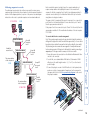
IMPORTANT: Power switching devices have a maximum current rating. It is
essential to ensure that the total current drawn by the equipment connected
to the power switching device does not exceed the current rating of the power
switching device. You must also ensure that the current drawn from any mains
socket does not exceed the current rating of the mains socket.
Setting up, configuring and using power switching requires three main steps:
• Connect and address the switch boxes ð
• Configure the power strings
• Operate remote power switching
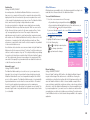
3 For each of the remaining switch boxes (if used), use a serial cable with RJ9
connectors at both ends (see Appendix 3 for specification). Connect one
end to the socket marked ‘OUT’ of the previous box and the other end to
the socket marked ‘IN’ of the next box.
4 Set the addressing switches on each switch
Box Switch 1 Switch 2
box using the two small switches marked
1
Off
Off
‘Slct’ on the front panel. The box connected
directly to the AdderView Matrix is Box 1
2
On
Off
and so on down the daisy-chain line to Box
3
Off
On
4 at the end.
4
On
On
5 Connect IEC to IEC power leads between
Off = switch upwards
each port and the power input socket
On = switch downwards
Switch 1 is on the left side
of each computer that requires power
switching. Carefully note to which power
ports, on which boxes, each computer is connected. If server systems have
multiple power inputs, then each input must be connected via separate
ports, which can be on the same, or different boxes.
6 Connect each box to a suitable mains power input.
Now proceed to the configuration stage covered in the Power switching
configuration section within the Configuration chapter.
Power
switch
boxes
Box 1
CO
AdderView Matrix
‘Daisy-chain’
control
connections
To connect and address the switch boxes
Note: The AdderView Matrix can be powered on during this procedure,
however, the switch boxes should be switched off.
1 Mount up to four switch boxes in positions where they are close to the
computers that they will control and not too distant from the AdderView
Matrix (preferably within 2.5 metres).
2 Use a serial cable with an RJ9 and a 9-pin D-type connector (see Appendix
3 for specification). Connect the RJ9 plug to the socket marked ‘IN’ on the
first switch box. Connect the other end to the socket marked ‘COM’ on the
AdderView Matrix.
A key feature of the AdderView Matrix is its ability to remotely control the
power of the computers attached to it. The actual power switching process
requires the use of optional switch boxes available from a number of suppliers
(Adder part number: PSU-8MASTER and PSU-8SLAVE), however, the AdderView
Matrix offers the control port for these switches and the necessary operational
integration within its menu system.
The control connector of the first power switch is connected, via serial cable,
to the rear panel of the AdderView Matrix. Any additional power switches are
then connected via a ‘daisy-chain’ arrangement to the first power switch. Each
power switch box is then given a unique address and access to each power port
(8 ports on each power switch box) is gained using a combination of the switch
box address and the port number.
Each power port can then be connected to the power inputs of each computer
and each power switch box then connected to a mains power supply.
Power switching connections
11
Cascade connections
User
2
Cascade
level 1
AdderView Matrix
Cascade
level 2
AdderView Matrix
AdderView Matrix
User
1
The AdderView Matrix supports up to eight (model
AVM208) or sixteen (model AVM216) directly
connected computer systems, however, this is
by no means the limit. Thanks to an intelligent
communication system, called Adder Port Direct,
many more computers can be controlled by
connecting other KVM switches to the AdderView
Matrix. The combination of switches can be arranged
up to four levels deep forming a tree, or cascade
arrangement, with computers situated at any level.
AdderView Matrix
Cascade
level 3
AdderView Matrix
AdderView Matrix
AdderView Matrix
AdderView Matrix
AdderView Matrix
AdderView Matrix
Cascade
level 4
AdderView Matrix
12
GROUP
28
GROUP
27
GROUP
26
GROUP
25
16
15
14
13
12
11
10
9
8
7
6
5
4
3
2
1
GROUP
24
GROUP
23
GROUP
22
GROUP
21
Note: Single links and dual link groups may be mixed on one switch providing
the dual link groups lie within the appropriate port boundaries shown above
- see Tips for successful cascading for more details.
Port boundaries and numbering for dual link groups (model AVM208 uses
groups 21 to 24 only)
The method for cascading switching units is straightforward and requires no
hardware settings or lengthy configuration process. This is due to the Adder
Port Direct communication system employed by most Adder switching products
that allows them to locate each other and share information.
The method of linking switches is the same regardless of the cascade level, or
number of devices attached. Put simply:
• A single cascade link is made by connecting a computer port of one
switch to a user port of the switch below it.
Such a single link would allow just one user from the higher switch to access
any of the computers (or other switches) attached to the lower one. However, a
single link can cause a bottleneck for multi-user systems, so it is commonplace
to make dual cascade links between switches. These allow two users to
simultaneously access computers situated anywhere within the cascade tree.
When dual cascade links are made between switches, each switch will
automatically recognise the dual links and treat them accordingly. The links
within a dual group will then be allocated to users according to their general
availability in that group, not as specific individual lines. To do this, each link
group has an access number, which is determined by the ports to which they are
connected on the switch.
For instance, a dual group connected to computer ports 1 and 2 of a switch
would always be known as 21, the next dual group connected to ports 3 and
4 would always carry the number 22, and so on. The diagram here summarises
the ports to which dual groups must be connected and the resulting group
numbers attained in the positions here ð
The central purpose of the link group system is that each user can use a unique
address to locate a particular computer, however, as with the Internet, the route
to get there could be slightly different each time. This avoids any route blocking
that could easily be caused by other users occupying any specific link lines.
How cascade connections operate
13
User
1
User
2
AdderView Matrix
AdderView Matrix
Group 23
at cascade
level 2
The unique address
of this computer is:
21 04
AdderView Matrix
Group 27
at cascade
level 3
AdderView Matrix
The unique address
of this computer is:
Port 02
at cascade
level 4
21 23 27 02
Port 04 at
cascade level 2
Group 21
at cascade
level 1
To connect switches in a cascade arrangement
Note: This procedure may be carried out in any order but for clarity this instruction
will begin at the higher level switch (here called the upper switch), i.e. the one that is
being fed into by a switch at the cascade level below (here called the lower switch).
The procedure given here remains the same regardless of exactly which cascade
levels are being connected. The basic rule is that each link is made by connecting a
computer port of the upper switch to a user port of the lower switch.
1 Ensure that power is disconnected from the AdderView Matrix and all other
switches to be connected.
2 For each link, use a standard Adder KVM cable set (Part number: VKVMxM where x is the cable length in metres: 1, 2, 5 or 10) - use the shortest
possible lengths.
3 Connect the plugs at one end of the KVM cable set to the keyboard, video
and mouse sockets of an appropriate Computer port on the rear panel of
the upper switch. Refer to the Group numbering diagram for the correct
link group boundaries.
21 04
21 23 27 02
Each cascade level requires two digits, hence the computer marked in red
requires a unique address with eight digits because it is at cascade level 4,
compared to the blue computer at level 2 with its four digit unique address. A
computer connected directly to the AdderView Matrix at the top level would
simply have a two digit port number.
The group at level 2 is numbered 23 because it is a group of two, connected to
ports 5 and 6 on the AdderView Matrix. If it was connected to ports 7 and 8,
then the group number would be 24.
If the group at level 3 was connected to ports 15 and 16 of the switch, then the
group number would be 28. This would make the address of the red computer:
21 23 28 02.
The addressing format used by the switches incorporates the various group
numbers along with a final specific port number to which a required computer is
attached. In the diagram given here, a portion of the previous cascade diagram
indicates how the routes to particular computers are formed and addressed.
Addressing computers in a cascade
continued
14
5 Repeat steps 3 and 4 for each of the links within the group, adhering to the
Group numbering diagram for the correct link group boundaries on the
computer ports on the upper switch.
Once the switches and computers have been connected, you can edit their
names to make it much easier to locate them. See the To create/edit computer
names section in the Configuration chapter for more details.
Tips for successful cascading
• The maximum number of levels for a cascade is four.
• The number of links between switches determines the number of users that
can simultaneously access the computers situated further down the tree.
• Keep all cascade cables as short as possible to maximise video quality.
• Ensure that dual cascade links (within a group) between switches are
approximately the same length.
• If SmartView Pro switches are used, ensure that they are situated at the
lowest level, with no AdderView Matrix or XPro switches below them.
• Single links and dual link groups may be mixed on one switch providing
the dual links lie within the appropriate port boundaries designated in the
Group numbering diagram.
To test a specific link
1 Simultaneously press and hold
and
.
Note:
and
are the standard hotkeys and can be altered to avoid
clashes with other devices or software. If you change the hotkeys, remember
to use the new ones in place of
and
when following these
instructions. For AdderView Matrix and AdderLink IP combinations, please
see the extra note below.
2 While still holding
and
, in sequence, press and release the full
address of the required computer – remember to use specific port numbers,
not link group addresses, e.g. port 01140203.
3 When the last digit has been entered, release all keys.
Hotkey clashes between AdderView Matrix and AdderLink IP
When using the AdderLink IP in conjunction with the AdderView Matrix it may
be necessary to change the standard hotkeys for one of the devices as they both
use
and
as their standard hotkeys. It is not important which device is
altered, however, ensure that the new setting does not clash with any software
being used on connected computers.
As mentioned previously, the best and most efficient way to access cascaded
computers is by using the on screen menu and via non-specific routes through
the link groups. However, during configuration or troubleshooting, it may be
useful to test specific routes to computers in order to verify the various strands
of each link group. By using specific port addresses for each switch, rather than
link group numbers, you can precisely navigate a route through any part of the
system.
Testing specific links to cascaded computers
In use, cascaded computers can be accessed using exactly the same methods
as for those connected directly to the AdderView Matrix. However, by far
the easiest way is to use the on screen menu. This is because it displays the
computer names and does not require any knowledge of port addresses, some
of which (as discussed above) can be up to eight digits long. See the Selecting
cascaded computers section in the Operation chapter for more details.
Using cascaded computers
4 Connect the plugs at the other end of the KVM cable set to the keyboard,
video and mouse sockets of a User port on the rear panel of the lower
switch. Due to the way in which ports within a dual group are dynamically
allocated, it is not usually important exactly which user port is connected to
each computer port of the upper switch.
15
Ensuring that the serial port is available
The AdderView Matrix has a single RS232 COM port which is used to send/
receive configuration data, control power switches and synchronise multiple
video head switching. The port can only be used for one of these tasks at any
one time. To use the COM port for multiple video head switching, ensure that
the power control option is disabled.
Slave AdderView Matrix
COM
2
1
2
1
USER PORTS
Serial
synchronisation
cable
COM
USER PORTS
Master monitor
COMPUTER PORTS
Master AdderView Matrix
Slave monitor
COMPUTER PORTS
Two or more AdderView Matrix units can be connected together so that
they operate in a synchronised manner. Synchronised operation is useful for
applications that require multiple video signals to be switched together. This
type of operation is usually required where each computer is fitted with multiple
video cards or video cards with multiple video heads. Such configurations are
typically required in banking and engineering applications where greater video
‘real estate’ is required. Whenever the AdderView Matrix channel is switched
it sends an RS232 command out on its serial interface (marked COM on the
rear panel). The AdderView Matrix switches its channel if it receives the same
command on its serial interface. Consequently, by linking the serial interfaces,
a master unit may be made to automatically switch one or more slave units as
shown in the diagram.
It should be noted that the synchronisation cable deliberately does not have the
transmit pin of the Slave End connector linked to the receive pin of the Master
End connector. To do so would cause the Slave unit to be able to switch the
Master unit. This would setup an endless cyclical switching sequence that would
prevent the AdderView Matrix devices from operating correctly. For more details
about the serial synchronisation cables, see Appendix 3.
Multiple video head connections
Computers fitted
with dual video
heads
16
When setting up a new AdderView Matrix installation, the following stages are
recommended:
1 Enable the ‘Security’ option within the Configuration menus.
With security disabled (default setting), all users attached to the AdderView
Matrix have full and unrestricted access to all computers and all AdderView
Matrix settings. In larger installations, you are strongly recommended to
enable security and set up individual user accounts with access privileges.
When also using the AdderLink IP, its integral security features provide
protection from unauthorised remote users - ensure that its security features
are also enabled (please see the AdderLink IP user guide for more details).
2 Create an ADMIN (administration) account password.
The AdderView Matrix has a fixed user account that cannot be deleted,
named ADMIN. This user account is the only one that is able to make
important system changes. If you intend to use security, then it is important
to allocate a password to the ADMIN account.
3 Create user accounts and allocate access rights.
Use the ADMIN account to add user profiles, passwords and access rights
for each of the system users.
4 Provide names for computers.
When numerous computers are attached, you are strongly advised to
provide names for each, to assist with recognition.
5 Configure the required ‘Setup Options’ and ‘Global Preferences’
Use the ADMIN account to determine key AdderView Matrix settings and
timing characteristics.
After all of the above steps are completed, the AdderView Matrix should be fully
configured.
• If you don’t need security (not recommended), skip
steps 1, 2 and 3.
• If you don’t need computer names, skip step 4
These steps can be completed at a later date.
When used with an AdderLink IP
• Ensure that security is enabled, follow steps 1
and 2.
• Unless a locally connected user is required to access
the computers, you do not need to create user
accounts or provide names for computers - all of
this should be carried out on the AdderLink IP, skip
steps 3 and 4.
• Unless a locally connected user is required to access
the computers, you do not need to configure Setup
Options or Global Preferences, skip step 5.
Overall initial configuration
In a hurry?
Almost all configuration and operational aspects of the AdderView Matrix are
controlled via on-screen menu displays.
Configuration
17
Identification of
this user port
Your Login name
2 Press
Port numbers
Connection status
of this user port
Assistance for
keypress options
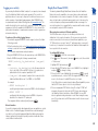
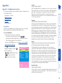
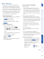
To display the Configuration Menu:
ADDERVIEW MATRIX
Configuration Menu
Functions
Routing status
User Preferences
Global Preferences
Setup Options
Edit Computer List
Edit User List
Edit Autoscan List
F1-More menus
Enter-Select
Esc-Quit
Firmware Version 2.08
3 Use the
and
keys to highlight an option, then press
Hotkey clashes between AdderView Matrix and AdderLink IP
When using the AdderLink IP in conjunction with the AdderView
Matrix it may be necessary to change the standard hotkeys for one of
the devices as they both use
and
as their standard hotkeys.
It is not important which device is altered, however, ensure that the
new setting does not clash with any software being used on connected
systems.
Whereas AdderView Matrix uses the hotkeys plus
to access its
menu, the AdderLink IP uses the hotkeys plus
to summon its menu:
AdderLink IP: What you will see if you
press the hotkeys plus C if security is
enabled ò and if it is not ð
AdderLink IP Logon
Username:
Password:
to select.
IMPORTANT: When supplied, AdderView Matrix has its security
features disabled, which means that any attached users have access
to all connected computers and all AdderView Matrix settings. You
are strongly recommended to enable the ‘Security’ feature and set
an access password for the ADMIN account.
Default names for
each computer port
ADDERVIEW MATRIX
Computer
Port
Computer 1
01
Computer 2
02
Computer 3
03
Computer 4
04
Computer 5
05
Computer 6
06
Computer 7
07
Computer 8
08
User port 1
Status
ADMIN
SHARED USE
F1-More menus F3-Find
Esc-Quit
F4-Logout
Security
Note: If the security option has been
ADDERVIEW MATRIX
User Name:
enabled, you will be asked for a valid
Password:
user name and password before the
Port 1 login
Esc-Scr Save
main menu can be displayed (user
names and passwords are not case sensitive).
To access the Configuration menu
1 If the main menu is not already displayed, press and hold
and then
press
using a keyboard attached to a AdderView Matrix user port.
The main menu will be displayed:
Hotkeys
Note:
and
are the standard hotkeys and can be altered
to avoid clashes with other devices or software - in particular, the
AdderLink IP device when it is used alongside (see below). If you
change the hotkeys, remember to use the new ones in place of
and
when following the instructions in this guide.
AdderLink IP Control
Logoff
Restore Mouse Functions
Configuration
Access Mode
Host
The configuration menus allow you to determine many aspects of the
AdderView Matrix capabilities. From here you can:
• Create individual user accounts and determine access rights,
• Provide names for all connected computers to allow quick recognition,
• Set individual and global settings for users,
• Run various functions, such as mouse restore operation,
• Save and load AdderView Matrix configuration settings, and more.
Configuration menus
Shared
Email server
Return To Host
18
Routing status
User Preferences
OSD Colour
Reminder Banner
Reminder Colour
Screen Saver Type
Confirmation Box
Global Preferences
Mouse Switching
Screen Saver
Autoscan Mode
Autoscan Period
OSD Dwell Time
User Timeout
RS232 Mouse Type
Mouse Type
Setup Options
Security
Language
Hotkeys
Keypad Controls
Exclusive Use
Automatic Logout
Edit Computer List
Edit User List
Edit Autoscan List
(F1) Advanced Options
DDC Options
Power Control
For a description of each option within the Configuration menus, see
Appendix 1 for more details.
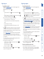
To set an ADMIN password
1 Display the Configuration menu.
2 Highlight ‘Edit User List’ and press
.
3 Highlight ‘ADMIN’ and press
. Press
again to accept the name
‘ADMIN’ without change.
4 Enter an appropriate password for the ADMIN user account with regard to
the following:
• The password can be up to 12 characters long.
• The password can use letters, numerals and/or certain punctuation
marks.
• The password is not case sensitive.
5 Press
. The ‘Edit Access Rights’ menu will be displayed. However, as the
ADMIN account always has access to all computers, press
again to save
the new password.
What to do if the ADMIN password has been forgotten.
To change the hotkeys
When using the AdderLink IP in conjunction with the AdderView Matrix it will
be necessary to change the standard hotkeys for one of the devices. They both
use
and
as their standard hotkeys, so only the first one in the chain
(usually the AdderLink IP) will respond to your requests. It is not important which
device is altered, however, ensure that the new setting does not clash with any
software being used on connected computers. The procedure shown here will
change the AdderView Matrix hotkeys, to alter the AdderLink IP hotkeys, please
see the AdderLink IP user guide.
1 Display the Configuration menu.
2 Highlight ‘Setup Options’ and press
.
3 Highlight ‘Hotkeys’ and press
to select the required hotkey
combination. The options are: CRTL+ALT, CTRL+SHIFT, ALT+SHIFT, ALT
GR, LEFT ALT+RIGHT ALT, LEFT CTRL+LEFT ALT, RIGHT CTRL+RIGHT ALT or
DISABLED.
4 Press
to return to the ‘Configuration Menu’.
Restore Standard Mouse
Restore Intellimouse
Power Control
Reset to Factory Defaults
Send Data to RS232 port
Read Data from RS232 port
Functions
Configuration Menu
To enable security
1 Display the Configuration menu.
2 Highlight ‘Setup Options’ and press
.
3 Highlight ‘Security’ and press
to select ‘ENABLED’.
4 Now create a new password for the ADMIN user account.
The menu options are arranged as shown here:
Configuration menus layout
19
Tips when creating/editing computer entries
• Avoid creating two names for the same computer port.
• When cascading to other KVM switch devices, do not apply individual
names to any ports that are forming a link group to another switch (i.e.
ports 1 and 2 when they form link group 21).
To create/edit computer entries
1 Display the Configuration menu. Note: You must be logged-in as the
ADMIN user.
2 Highlight ‘Edit Computer List’ and press
.
3 Either:
• Create a new computer entry – Press
and enter a new name, or
• Edit an existing computer entry – Highlight a computer name and press
. Press
(Backspace) to delete existing characters and enter the
required new name (up to 16 characters).
4 Press
and the cursor will move to the computer port column on the right
side. Change or enter the port address of the computer as required. See
the Addressing computers in a cascade section for more details. When
the port address is complete, press
. The ‘Edit access rights’ menu will be
displayed. Here you can determine which users should have access to the
created/edited computer. Only users that show a ‘+’ marker to the right of
the menu box will be granted access to the computer.
Note: The Adder Port Direct feature (which allows interconnected Adder
KVM switches to talk to one another) ensures that users without access
rights to particular computers cannot move sideways to those computers via
other computers.
Note: Access rights for particular user accounts to computers can also be
controlled from the ‘Edit User List’ menu
5 Select and deselect users as follows:
• Individual user - Highlight a user name, then press
to apply, or
remove, the ‘+’ marker.
• Allow access for all users – Press
• Allow no user access (except ADMIN) – Press
6 When all settings have been made, press
to save and exit. Press
to
return to the ‘Configuration Menu’.
To create/edit user accounts
1 Display the Configuration menu. Note: You must be logged-in as the
ADMIN user.
2 Highlight ‘Edit User List’ and press
.
3 Either:
• Create a new account - Press , enter a new user name and press
,
or
• Edit an existing account - Highlight the required user name and press
Edit the name, if appropriate, and/or press
.
4 Enter or edit the password with regard to the following:
• The password can be up to 12 characters long.
• The password can use letters, numerals and/or certain punctuation
marks.
• The password is not case sensitive.
• The password field can remain blank to allow open access to this
account.
5 Press
to display the ‘Edit Access Rights’ menu. Here you can determine
which of the connected computers can be accessed by the selected user
account. Only computers that show the ‘+’ marker to the right of the menu
box will be accessible to the user account.
Note: The Adder Port Direct feature (which allows interconnected Adder
KVM switches to talk to one another) ensures that users without access
rights to particular computers cannot move sideways to those computers via
other computers.
Note: Access rights for user accounts to particular computers can also be
controlled from the ‘Edit Computer List’ menu.
6 Select and deselect computers as follows:
• Individual computer - Highlight a computer name, then press
to
apply, or remove, a ‘+’ marker.
• Access to all computers – Press
• Access to no computers – Press
7 When all settings have been made, press
to save and exit. Press
to
return to the ‘Configuration Menu’.
Registering computers
Registering users
20
To view autoscan
• At one of the user ports, press
.
Note:
and
are the standard hotkeys and can be altered to avoid clashes
with other devices or software - in particular, the AdderLink IP device when it is
used alongside. If you change the hotkeys, remember to use the new ones in
place of
and
when following these instructions.
To define an autoscan list
Note: This stage is required only when the ‘Scan List’ autoscan mode is selected.
1 Display the Configuration menu. Note: You must be logged-in as the
ADMIN user.
2 Highlight ‘Edit Autoscan List’ and press
. A list of all connected computers
will be displayed. Only computers that show a ‘+’ marker to the right of the
menu box will be autoscanned.
3 Select and deselect computers to scan as follows:
• Individual computer - Highlight a computer name, then press
to
apply, or remove, the ‘+’ marker.
• Mark all computers for scanning – Press .
• Unmark all computers – Press .
4 When all settings have been made, press
to save and exit. Press
to
return to the ‘Configuration Menu’.
To select an autoscan period
1 Display the Configuration menu. Note: You must be logged-in as the
ADMIN user.
2 Highlight ‘Global Preferences’ and press
.
3 Highlight ‘Autoscan Period’ and press
until the required time to view
each computer is displayed, ranging from 2 seconds to 5 minutes.
To select an autoscan mode
1 Display the Configuration menu. Note: You must be logged-in as the
ADMIN user.
2 Highlight ‘Global Preferences’ and press
.
3 Highlight ‘Autoscan Mode’ and press
until the required option is
displayed: SCAN LIST, ACTIVE PCs or ALL PCs.
The AdderView Matrix provides an autoscan mode that switches between
the connected computers in sequence. This mode is useful to allow users
and administrators to sample activity among the connected machines. Three
scanning modes are provided:
• Scan list – Only computers declared within an autoscan list will be viewed.
Computers connected to cascaded switches can be included in the autoscan
list.
• Active PCs – Only computer ports where an active computer is detected will
be viewed. This mode avoids blank screens from being displayed and helps
to prevent the viewing monitor from entering a power-down state on every
scan cycle. Computers connected to cascaded switches will not be viewed in
this mode.
• All PCs – This mode visits, in turn, each computer that is connected directly
to the AdderView Matrix. This mode should be used with care due to the
reasons given in the warning below. Computers connected to cascaded
switches will not be viewed in this mode.
The scanning mode is a global setting and hence will be the one viewed by any
user who selects
on their keyboard. Note, however, that users will
only see the scanned computers to which they have access rights. Hence, if two
users (with various access rights) simultaneously view an autoscan, they will see
differing results depending upon their respective permissions.
WARNING: Many modern monitors are fitted with automatic power
saving relays that switch off after a few seconds when connected to
an inactive computer. If you are using such a monitor, do not set the
AdderView Matrix to the scan ‘ALL PCs’ mode. Continual switching on
and off of the monitor’s relay will eventually damage the monitor. If
using such a monitor in conjunction with the ‘Scan List’ option, ensure
that all selected computers are active.
There are up to three steps that need to be configured to use autoscanning ð
• Select the autoscan mode: Scan List, Active PCs or All PCs.
• Select the autoscan period. This is the time that is spent viewing each
computer. This step also enables and disables the autoscan feature.
• Define the autoscan list. This step is only required when the Scan List option
is selected and allows you to select which computers will be scanned.
Autoscanning
21
To save configuration settings
1 Run the program XPREAD.EXE on the computer that is connected to the
AdderView Matrix’s serial port. Follow the instructions given by the program.
2 Using one of the AdderView Matrix user ports, display the Configuration
menu. Note: You must be logged-in as the ADMIN user.
3 Highlight ‘Functions’ and press
.
4 Highlight ‘Send Data to RS232 port’ and press
.
5 The AdderView Matrix will send the configuration data to your computer.
The XPREAD program will store the data in a file named ‘XPRODATA.CSV’
that will be created in the same directory where the XPREAD program was
started - Ensure that you have sufficient rights to write to this directory.
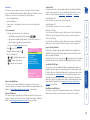
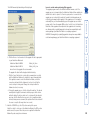
Hints for editing
• To grant a user access to a computer, enter the value ‘1’ in the box that is
common to the computer’s row and the user’s column.
• To deny access, leave the box blank.
• To add extra users, add additional columns (up to 16 users).
• To add extra computers, add additional rows (up to 512 computers).
• The ADMIN user will always be granted access to all computers regardless of
the values entered.
To restore configuration settings
Note: Ensure that the computer is connected to the AdderView Matrix as
discussed earlier in the ‘Preparations’ sub section.
1 Copy the program XPWRITE and XPRODATA.CSV into the same directory on
the computer connected to the AdderView Matrix’s serial port.
2 Run the program XPWRITE.EXE and follow the instructions given by the
program.
3 Using one of the AdderView Matrix user ports, display the Configuration
menu. Note: You must be logged-in as the ADMIN user.
4 Highlight ‘Functions’ and press
.
5 Highlight ‘Read Data from RS232 port’ and press
.
6 The AdderView Matrix should then receive the configuration data from the
computer and load the new menu names and access rights into the menu.
• Log on to the Adder Technology website at www.adder.com and download
the files XPREAD.EXE and XPWRITE.EXE.
• Connect the serial port on the rear panel of the AdderView Matrix, labelled
‘COM’, to a serial port on your computer using the optional serial flash
upgrade cable available from Adder (p/n: CAB-9M/9F-2M). See Appendix 3
for pin-out specifications.
• Ensure that the serial port is available. The AdderView Matrix has a single
RS232 COM port which is used for various functions. The port can only be
used for one task at any one time. To use the COM port for configuration
saving/loading, ensure that the power control option is disabled.
Preparations for configuration save/load
To edit the configuration settings
The saved XPRODATA.CSV file can be opened using a spreadsheet program such
as Microsoft Excel. The format of a typical file is shown below. You will see that
the computer names (rows) are tabulated against the user profiles (columns):
USERS
ADMIN
Alan
Jim
Sue
Test
PASSWORDS
password letmein hello logmein Test
COMPUTERS
PORT
Admin PC
2103
1
1
1
1
Alan’s System
2102
1
1
1
Comms Server
3
1
1
Comms PC
4
1
1
1
1
Gateway 1
8
1
Gateway 2
5
1
Test System
15
1
1
Web Browser
9
1
1
1
The AdderView Matrix can store up to 512 computer names and 16 sets of
user access rights. Particularly in cascaded configurations, manually re-entering
all computer names, port numbers and access rights can be a lengthy process.
Therefore, the AdderView Matrix provides a method to save and, if required,
restore configuration settings using one of its serial ports. Further to this, the
saved file can be opened and edited within a spreadsheet and then restored
back to the AdderView Matrix – a useful way to make multiple setup changes.
Note: You must be logged-in as the ADMIN user for this procedure.
Saving and restoring configuration settings
22
To set the serial port for non-power control functions
1 Display the Configuration menu. Note: You must be logged-in as the
ADMIN user.
2 The ‘Functions’ option should be highlighted, press
.
3 Press
to display the ‘Advanced Options’ menu.
4 Highlight the ‘Power Control’ option and press
. Check that the ‘Power
Control’ option is ‘DISABLED’. If not, highlight it and press
to change it.
5 Press
to quit the screen and save the settings.
To perform a complete reset and return the AdderView Matrix to its
factory default state:
1 Power on the AdderView Matrix normally.
2 Whilst the AdderView Matrix is powered on move switch 2 on the rear panel
of the AdderView Matrix (labelled UPGRADE) to the ON (down) position.
3 Press the USER and the COMPUTER keys together.
4 The green USER display will show ‘ ’ for a few seconds to confirm that a
reset is taking place.
5 Return switch 2 to the normal OFF position (up).
The AdderView Matrix has a single RS232 serial port which can be used to:
• Control power switches,
• Send/receive configuration data, and
• Synchronise multiple video head switching.
The port can only be used for one of these tasks at any one time. For the latter
two functions to be possible, the Power Control option must be disabled.
Ensuring that the serial port is available for other functions
If the ADMIN password becomes mislaid or forgotten, you will not be able
to access the AdderView Matrix to add or edit users and computer names.
This situation may be resolved by performing a complete reset to return the
AdderView Matrix to its factory default state.
IMPORTANT: A complete reset erases all the user names and computer
names that you have setup. You can only perform a complete reset if you
have access to both the front and the rear of the AdderView Matrix.
What to do if the ADMIN password has been forgotten
23
Recognising an IntelliMouse-style mouse
The IntelliMouse format was introduced to support, among other features, the
scroll wheel function. If the mouse has a scroll wheel, then it is likely to support
the IntelliMouse format. If it is a Microsoft-branded mouse, then it will usually
state that it is an IntelliMouse on its underside label.
Recognising an IntelliMouse driver
Before hot plugging to the AdderView Matrix (or afterwards using only keyboard
control), access the Windows Control Panel of the computer and select either
the Mouse option (on Windows NT, 2000 and XP) or the System option (on
Windows 95, 98, ME). Look for the name of the driver, which will usually
include the words PS/2 or IntelliMouse.
The general rule is that unless both the mouse and the driver are both
IntelliMouse compatible then you need to restore the mouse as ‘PS/2’. An
IntelliMouse can operate in either mode, whereas a PS/2 mouse cannot.
Which restore setting do I use?
To restore mouse operation when hot plugging:
1 Using a KVM cable set, carefully make the connections between the
keyboard, monitor and mouse sockets of the computer and the required
AdderView Matrix port.
2 Select the port of the newly connected computer and then display the
Configuration menu.
3 Highlight ‘Functions’ and press
.
4 As appropriate, highlight one of the following options:
• Restore Standard Mouse – if PS/2 mode is required, or
• Restore IntelliMouse – if IntelliMouse mode is required.
Then press
.
5 Move the mouse a short distance and check for appropriate on-screen
cursor movement. If the mouse cursor darts erratically around the screen,
then cease moving the mouse. This is an indication that the chosen restore
function is incorrect. Try again using the other restore function.
Note: The restore functions predict the likely mouse resolution settings but
may not restore the exact speed or sensitivity settings that were originally
set.
It is strongly recommended that you switch off a computer before attempting
to connect it to the AdderView Matrix. However, if this is not possible then you
need to ‘hot plug’ the computer while it is still running. There is not normally
a danger of damage to the computer, however, when mouse communications
are interrupted, often they fail to re-initialise when reconnected. The AdderView
Matrix provides a feature to reinstate mouse communications once the necessary
connections have been made.
There are two main types of data formats used by current PC mice, these are
the older ‘PS/2’ or ‘standard mouse’ format and the more recent ‘IntelliMouse®’
format introduced by Microsoft. These use slightly different data arrangements
and it is important to know which type was being used before you hot-plugged
the computer to the AdderView Matrix. The previous setting depends both on
the type of mouse and the type of driver, as various combinations of PS/2 and
IntelliMouse are possible. Using the incorrect restore function may produce
unpredictable results and require the computer to be re-booted.
Hot plugging and mouse restoration
24
To disable mouse acceleration
1 On the computer connected to the AdderView Matrix, access the Mouse
driver within the Control Panel.
2 Locate and disable the setting variously labelled as ‘Mouse acceleration’ or
‘Enhance pointer precision’.
Note: If a remote computer has mouse acceleration enabled and you need to
disable it remotely, then it can be difficult to accurately position the remote
cursor. In this case, display the AdderView Matrix menu (
). While
it is displayed, you can move the your local cursor to the required screen
position and then deactivate the on screen menu.
Certain operating systems, such as Windows XP provide an option to use
‘mouse acceleration’ or ‘Enhance pointer precision’. If this option is enabled on
a computer connected to the AdderView Matrix it can cause problems when
accessed via a remote IP link (when using the AdderLink IP). Generally, the
remote mouse pointer becomes erratic and difficult to control. For this reason,
you are strongly recommended to disable such features on computers that will
be accessed remotely.
To perform a power-off reset for a selected user port
1 Press the USER key on the front panel of the AdderView Matrix to select the
user port whose keyboard and mouse you wish to reset.
2 The selected user port number should now be shown on the green USER
display.
3 Press and hold down the USER key for 5 seconds until the green USER
display goes off. The keyboard and mouse will then be powered off.
4 As soon as the green display goes off, release the USER key. The green
display will then resume and a few seconds later the keyboard and mouse
will be powered on, ready for use.
Disabling mouse acceleration
The AdderView Matrix provides the option to perform a complete power off
reset of the keyboard and mouse that are connected to a selected user port. This
can be useful if you wish to disconnect the keyboard or mouse and replace them
with alternatives. Keyboards will enable themselves automatically if they are
disconnected and then re-connected to the AdderView Matrix. Mice, however,
will not normally re-enable themselves after they have been disconnected and
re-connected although they will do so automatically if the AdderView Matrix
channel has been changed whilst the mouse is disconnected.
Consequently you will normally need to perform a power-off reset of the user
port if you have disconnected and re-connected a mouse. The power off reset
function only affects the selected user port and does not affect any of the
computer connections or any of the other user ports.
Resetting user port keyboards and mice
25
Power switching configuration
To configure the power strings for each computer
1 Switch to the computer port whose power port(s) need to be set.
2 Display the Configuration menu. Note: You must be logged-in as ADMIN user.
3 The ‘Functions’ option should be highlighted, press
.
4 Highlight ‘Power Control’ and press
.
5 Highlight ‘Edit Power ON String’ and press
.
6 Edit the power switch string according to the guidelines given overleaf in the
Editing power strings section. If the current computer port requires more
than one power port, press
to begin editing the next string for the next
associated port. Up to four ports may be grouped in this way.
7 Press
to save and exit.
8 Repeat steps 5 to 7 for the corresponding ‘Edit Power OFF String’.
For details about operating this feature, see Using remote power
switching section within the Operation chapter.
To configure the power-control serial port
1 Display the Configuration menu. Note: You must be logged-in as the
ADMIN user. The settings given below are for the PSU-8MASTER and
PSU-8SLAVE power switches - other power switches may require different
settings.
2 The ‘Functions’ option should be highlighted, press
.
3 Press
to display the ‘Advanced Options’ menu.
4 Highlight the ‘Power Control’ option and press
. Check that the ‘Power
Control’ option is ‘ENABLED’. If not, highlight it and press
to change it.
5 Check that the ‘Baud Rate’ entry shows ‘9600’. If not, highlight it and press
to change it.
6 Check that the ‘Format’ entry shows ‘NONE.8.1’. If not, highlight it and
press
to change it.
7 Press
to quit the screen and save the settings.
Power switch configuration comprises three main steps:
• Configure the serial port to the same settings used by the power switch boxes.
• Configure a power ON string for each power port.
• Configure a power OFF string for each port.
The procedures used to achieve the latter two steps are almost identical. For
each power port there needs to be a valid ‘Power ON string’ and similarly an
appropriate ‘Power OFF string’. In each case, the strings are a short sequence
of characters that combine a port address and a power on or off value. Where
a particular computer has more than one power input (and thus requires an
equivalent number of power ports to control them), collections of strings can be
associated to switch all of the required ports together as a group.
26
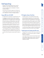
Power String [HEX]
50 31 38 3D 31 0D
Press F1 to change
between the ASCII
and HEX editing
areas
HEX editing
area
Strings apply to
Computer : Computer 8
Port : 08
F1-ASCII/Hex Toggle
F2-Next String
Esc-Quit
Enter-Save
The two areas are linked so that as you change one, the other changes in
response. The ASCII edit area has two limitations:
• The ASCII edit area cannot display the ‘=’ character, and represents it with
a fullstop when you type ‘=’. However, even though it is not displayed, the
character is correctly stored and used.
• You cannot add the ‘Enter’ character (which is needed at the end of the
line) within the ASCII edit box. This must be added within the HEX area,
using the code ‘0D’ (zero, not the letter ‘O’). The ‘Enter’ character is also
represented in the ASCII area by a fullstop, so the HEX area provides the
truest representation of the string contents.
Example 2
To switch OFF port 8 of switch box 3, the ASCII and HEX codes would be as follows:
• ASCII string:
P38=0
• HEX characters: 50 33 38 3D 30 0D
ASCII characters and equivalent HEX codes
The table given here shows the various ASCII characters that you will need along
with their HEX equivalents:
ASCII
P
1
2
3
4
5
6
7
8
=
Enter
Hex
50
31
32
33
34
35
36
37
38
3D
0D
To change between the ASCII and HEX edit areas
• Press
Note: Remember, you cannot add the ‘Enter’ command within the ASCII area,
you must change to the HEX area (using ) and type the equivalent code ‘0D’.
The structure of power strings
Note: The settings given below are for the PSU-8MASTER and PSU-8SLAVE
power switches - other power switches may require different settings. Please
refer to Adder for advice on how to configure the AdderView Matrix to control
other power switches.
The ASCII structure of each string (OFF and ON) is as follows:
Creating power port groups
Pxy=z
Where:
x is the switch box number,
y is the power port number,
z is ‘0’ for OFF or ‘1’ for ON, and
is the Enter (or Carriage return) character (0D in Hex).
Where multiple power inputs to a server require simultaneous switching, up to
four ports can be formed into a power port group.
To add/edit further power strings in order to switch extra ports
1 Edit the first power ON string as described above.
2 Press
to edit an additional power ON string. Input the appropriate switch
box number and port address for the next power port.
3 Repeat step 2 for each power port that must be simultaneously switched.
4 Repeat all of these steps for the corresponding power OFF strings.
Note: The second, third and fourth strings are actually sent in quick succession.
If required, this feature could be used to create one long string for a single port.
1
Edit Power ON String
Power String [ASCII]
P18.1.
ASCII editing
area
Example 1
To switch ON port 5 of switch box 2, the ASCII and HEX codes would be as follows:
• ASCII string:
P25=1
• HEX characters: 50 32 35 3D 31 0D
The string editing screen has two editing areas where you can enter and view
the power switch code as either: ASCII characters or HEX values.
Editing power strings
27
XPLOG {activity_log_destination} {com_port}
where:
• {activity_log_destination} is the file name where the
log is to be stored or the word PRINT if the log is to be printed on a
printer attached to the computer’s parallel port. LPT1
• {com_port} is the computer’s serial port that is connected to the
AdderView Matrix. Options are 1 (for COM1) or 2 (for COM2).
For example:
• XPLOG datalog.txt 1
would log activity information received on COM1 to the file datalog.txt.
• XPLOG PRINT 2
would print activity information received on COM2 to the printer
attached to the computer’s LPT1 printer port.
These programs will run continuously until you press
.
More information
If you wish to integrate activity data logging with your own applications, contact
Adder for a list of serial data logging codes and their associated meanings. It
is possible to use the activity logging and AdderView Matrix synchronisation
features together but this requires a specially constructed serial cable. Please
contact Adder for further details.
To configure DDC settings
1 Press
to select the on-screen menu.
2 Press
to select ‘More menus’, then press
again to select the next level
of ‘More menus’.
3 Highlight DDC Options and press
.
4 Ensure that the DDC Function option is set to ENABLED. If not, highlight it
and press
to change its setting.
5 Choose the DDC Source. Highlight this option and press
to specify
a particular user port, or choose AUTO - this begins with user port 1 and
moves to the other port if a valid DDC monitor is not found.
Note: Where the two connected monitors have different capabilities, ensure
that the DDC Source option is set to look only at that port.
6 Choose an appropriate DDC Refresh setting. The setting AT START will
interrogate the monitor(s) selected in the DDC Source option whenever
the AdderView Matrix is switched on. When DISABLED, no new DDC
data is sought and existing information is used. When viewing this menu,
press F8 to perform a discover DDC information from the chosen user port
immediately.
When using two monitors of different capabilities
The DDC feature can use only one set of monitor specifications in its
declarations to the connected computers. This becomes an issue when the
monitors connected to the two user ports have different capabilities, e.g. a
15” VGA monitor on user port 1 and a 17” multiscan monitor on user port 2.
In such cases, it is important to ensure that the AdderView Matrix samples the
lower specified of the two monitors.
The industry standard Display Data Channel feature allows the AdderView
Matrix to discover the capabilities of a user port video monitor and transmit
that information to the connected computers. This helps to reduce incidents
where too high a video resolution/frequency signal is sent to the user port by
a selected computer, resulting in an unreadable or blank screen image. For
successful operation, it does require that the computers and their video circuitry
are configured to respond to DDC information.
To make use of the activity logging features
1 Download the program XPLOG.EXE from the support section of the Adder
Technology website.
2 Follow the instructions in the section Saving and restoring configuration
settings to create the Excel compatible file XPRODATA.CSV that contains a
list of user and computer names and port numbers.
3 Copy the XPRODATA.CSV file into the same directory as the XPLOG.EXE file.
4 Run the XPLOG file using the following command format:
Display Data Channel (DDC)
By connecting the AdderView Matrix’s serial port to a computer, a time stamped
log of the AdderView Matrix’s activity can be generated. This is useful for
applications where it is necessary to keep track of which users have accessed
which computers. A simple data logging program, called XPLOG.EXE, may
be downloaded from the Adder Technology website (www.adder.com). This
enables the activity log to be saved to a file or printed to a printer. This logging
program uses the Excel-compatible file XPRODATA.CSV to cross reference the
port and user information to computer and user names in order to generate an
informative activity log.
Logging access activity
28
Adder Port Direct is a totally transparent communication system that allows
compatible KVM switches and remote access devices to communicate with each
other. Using the keyboard connections that link each device, Adder Port Direct
allows:
• A controlling device to provide address details of the required port, the user’s
name and access rights, mouse calibration and video mode information.
• A controlled device to confirm the address and other details of the current
port.
Such communication simplifies both the configuration and selection of systems
within a complex cascade structure. It also provides excellent security control as
unauthorised users are prevented from achieving what is sometimes possible on
simpler KVM switching systems. That is, to use the hotkey and mouse switching
features to connect to servers for which they do not have access priviledges via
the on-screen menu. This is termed ‘sideways movement’ and is thwarted by
the Adder Port Direct feature because each unit is fully informed of each user’s
precise access rights.
Devices that support Adder Port Direct include the AdderView Matrix AVM208
and AVM216), the AdderLink IP, SmartView XPro and certain KVM switch
devices from other manufacturers with specific APD capabilities.
Adder Port Direct
29
Operation
Computer button and
numeric indicator
User button and
numeric indicator
User port activity
indicators
Power
indicator
Computer button and numeric indicator
These items allow you to select any one of the AdderView Matrix’s sixteen
(AVM216) or 8 (AVM208) computer ports. As the button is pressed, the
number shown by the red numeric indicator will increment to the next
available computer channel. The computer port selected will then be
connected to the user port that is currently chosen by the adjacent user
button and green numeric indicator.
User button and numeric indicator
These items allow you to select either of the AdderView Matrix’s two user
ports. With each press of the button, the number displayed by the green
numeric indicator will change between port 1 and port 2. At the same
time, as each user port number is displayed, the computer port that is
currently associated with that port will be indicated by the red numeric
indicator.
User port activity indicators
These two red indicators provide confirmation that keyboard and mouse
activity is being detected from each of the two user ports.
Power indicator
Glows green whenever power is applied to the AdderView Matrix.
The AdderView Matrix front panel provides a range of buttons, indicators and
connectors.
The front panel controls
The AdderView Matrix does not have a power switch, so whenever power is
applied via the supplied adapter, the unit is operational. A green indicator on the
front panel (labelled ‘Power’) shows power input status.
Note: Before applying power to the AdderView Matrix, ensure that the two
option switches at the rear panel are both set to the OFF (up) position.
Powering on
30
Using the AdderView Matrix
Default names for
each computer port
Identification of
your user port
Your Login name
ADDERVIEW MATRIX
Computer
Port
Computer 1
01
Computer 2
02
Computer 3
03
Computer 4
04
Computer 5
05
Computer 6
06
Computer 7
07
Computer 8
08
User port 1
Status
ADMIN
SHARED USE
F1-More menus F3-Find
Esc-Quit
F4-Logout
This column shows
the AdderView
Matrix address for
each computer. If you
wanted to select ports
using the hotkey
method, these are
addresses that you
would enter.
The login screen - here you enter a valid User Name and Password – see
Logging in and out for more details. When you do so, the AdderView
Matrix selection menu will be displayed:
Enter your Login
name here
To select a computer using the front panel controls
Note: It is possible for the front panel controls to be limited to selecting only
the on screen menu or a blank screen. If this is the case please use a different
switching method or contact your system administrator for details.
1 Press the User button until the green numeric indicator displays the port
number to which your keyboard, video monitor and mouse are connected.
2 Press the Computer button until the red numeric indicator shows the
required computer port number.
Note: If security has been enabled then only computer ports to which the
current user port has permission will be displayed.
As well as the sixteen (or eight) standard computer ports, there are also two
additional special ports that appear after port 16 and before port 1:
This port provides no video signal so that a connected power saving
monitor will be prompted to enter into its power saving mode.
This port connects the current user port to the on-screen menu.
ADDERVIEW MATRIX
User Name:
Password:
Port 1 login
Esc-Scr Save
To select a computer using the on-screen menu
1 Select the on-screen menu in one of three ways:
• By simultaneously pressing and then releasing
.
Note: The
and
keys when pressed in combination are called
‘hotkeys’ and they signal to the AdderView Matrix that you wish to
control it, rather than the computer. However, if these particular hotkeys
clash with another device or program, then your administrator may
change them to a different combination. If the
combination
fails to work, then please contact the system administrator for details.
• By pressing the middle and right buttons of a three button mouse, or
Note: The mouse switching option is usable only if the Mouse switching
option is enabled. See Global preferences for more details.
• By selecting port using the front panel buttons (see previous).
At this point, depending on the security settings and the current log in
situation, one of two things will be displayed, either the login screen, or the
Selection menu:
Note: When the AdderView Matrix is used in conjunction with an AdderLink IP
(and security is enabled), the AdderView Matrix will automatically enter a slave
mode. In slave mode, the on-screen menu, hotkeys and mouse button switching
are unavailable to all users connected via the AdderLink IP, except the admin
user. Users connected locally to the AdderView Matrix can continue to use the
switching methods described here.
There are four main ways to connect a particular user port to a specific
computer port:
• Using the front panel controls (discussed below) – this is a straightforward
method, if the AdderView Matrix is nearby.
• Using the on-screen menu (shown right) – this is the best method when
there are many connected computers.
• Using hotkeys – this is a good method if you continually access a small
number of computers.
• Using mouse buttons – this is a good method for switching between a
small number of computers.
For all methods (if the confirmation box option is enabled), when the
required port is selected, a pop up message will be displayed to confirm the port
connected to, and its status. Alternatively, an error message explaining why a
connection is not possible (press
to cancel the latter type of message).
Selecting a computer
Connection status
of your user port
The Selection Menu – here you can select computers by name.
31
To select a computer using mouse buttons
Note: This procedure works only with three-button or IntelliMouse devices and
only if the ‘Mouse Switching option’ has been enabled by your administrator.
1 Hold down the middle button (or scroll wheel) of the mouse.
2 Click the left mouse button to select the next computer port. When the
correct port is reached, release the middle button.
Note: If security has been enabled then only computer ports to which you
have permission will be displayed.
To select a computer using hotkeys
1 Simultaneously press and hold
and
.
Note: The
and
keys when pressed in combination are called
‘hotkeys’ and they signal to the AdderView Matrix that you wish to control
it, rather than the computer. However, if these particular hotkeys clash with
another device or program, then your administrator may change them to a
different combination. If the
combination fails to work, then please
contact the system administrator for details.
2 While still holding
and
, press the first numeral of the required port
address, then:
• If the port address is a single character, release all of the keys.
• If the port address is two or more characters, release the first numeral
key and press the second – repeat this procedure until all of the port
address numerals have been entered, then release
and
.
Note: The numbers on your keyboard’s numeric keypad are not valid, use
only the numeral keys above the QWERTY section.
Note: If your user port does not have authorisation to view the selected port
then an ‘Insufficient user rights’ messages will be displayed.
Standard hotkeys
The range of hotkey combinations are as follows:
Note: If your hotkeys have been changed, substitute them for
and
in
the examples given here.
Selects port 1
Selects port 2
•
•
•
•
then
Selects port 10
•
•
then
Selects port 16
Selects the next available port
Selects autoscan mode where each (authorised)
port is displayed for a period determined by
the administrator. To cancel autoscan mode,
simply select any fixed channel using any of the
suggested methods.
Switches off the video signal – this will cause
a power saving monitor to enter its standby
mode. To awaken the monitor, simply select
any fixed channel using any of the suggested
methods.
Logs out the current user (if security is enabled)
or selects port 0 to disable the video signal (if
security is disabled).
& , ,
or
Moves the currently displayed on-screen menu
around the screen.
2 Use the
and
keys (or the scroll wheel of an IntelliMouse) to highlight
the required computer name. Alternatively (for large configurations), press
to perform an alphabetical search for a particular port name.
Note: If security has been enabled then only computer ports to which the
current user port has permission will be displayed.
3 Select the highlighted port in one of three ways:
• Shared use - press
- This standard method allows other users to view
the same computer port. Control of the port is given to one user at a
time, on a first-come, first-served basis and is relinquished after a certain
period of inactivity.
• Exclusive use - press
– This mode prevents any other user from
viewing or controlling the computer port until you either select another
computer or log off. This mode should be used with care – it can also be
blocked as an option by the administrator.
• Video Only - press
– This mode displays the video picture of
the port, but prevents keyboard or mouse activity from controlling the
computer.
32
2 Enter your designated User Name and press
.
3 Enter your designated Password and press
. If both entries are correct
then the selected port will be displayed.
Note: If either the User Name or Password are incorrect, the entries will be
cleared to allow another attempt.
To log out from the AdderView Matrix
1 Select the on-screen menu in one of three ways:
• By simultaneously pressing and then releasing
.
Note: The
and
hotkeys may have been changed. If the
combination fails to work, then please contact the system administrator
for details.
• By pressing the middle and right buttons of a three button mouse, or
• By selecting port using the front panel buttons
2 Press . The login window will be displayed.
Alternatively:
• Press
and
at any time to log out.
ADDERVIEW MATRIX
User Name:
Password:
Port 1 login
Esc-Scr Save
To log in to the AdderView Matrix
1 If it is not already displayed, move the mouse or press any key to display the
log in screen.
The AdderView Matrix features a straightforward security system that helps to
prevent unauthorised access to some, or all connected computers.
Note: If an AdderLink IP is fitted and you are a remote IP user, then a separate IP
login and password are required in addition to (and in advance of) these details
– see Logging in and out for more details.
If the security option has been selected by your administrator then you will be
asked to enter a User Name and Password when you first access a user port.
When you have finished using the computer, it is then good practice to logout,
forcing any other users to authenticate themselves prior to use.
Note: If the security option has not been enabled then no login is required.
Logging in and out
To select a computer using mouse buttons – Advanced method
1 Select the on-screen menu by pressing the middle and right buttons of a
three button mouse.
2 Use the scroll wheel to highlight the required computer port.
3 Then, select either:
• Shared Use - press the left mouse button - This standard method allows
other users to view the same computer port. Control of the port is
given to one user at a time, on a first-come, first-served basis and is
relinquished after a certain period of inactivity.
• Exclusive Use - press
and the left mouse button – This mode
prevents any other user from viewing or controlling the computer
port until you either select another computer or log off. This mode
should be used with care – it can also be blocked as an option by the
administrator.
• Video Only - press
and the left mouse button – This mode displays
the video picture of the port, but prevents keyboard or mouse activity
from controlling the computer.
• Escape without selecting a port – press the right mouse button.
33
The AdderView Matrix provides the option of a confirmation box that is
displayed on screen for three seconds after
Computer
Port
a computer is selected. The confirmation
Computer 1
01
box indicates the current user port and your
Status
User port 1
user name, the selected computer and the
ADMIN
SHARED USE
connection status. You can enable or disable
the confirmation box, as required.
To enable/disable the confirmation box
1 Select the on-screen menu in one of three ways:
• By simultaneously pressing and then releasing
.
• By pressing the middle and right buttons of a three button mouse, or
• By selecting port using the front panel buttons
If you are not already logged in, do so now.
2 Press
to select ‘More menus’.
3 Highlight the ‘User Preferences’ option and press
to select.
4 Highlight the ‘Confirmation Box’ option and press
to select
‘ENABLED’ or ‘DISABLED’, as required.
5 Press
to save the settings. Press
twice more to return to the computer
port and view your changes.
To change banner colours or disable the banner
1 Select the on-screen menu in one of three ways:
• By simultaneously pressing and then releasing
.
• By pressing the middle and right buttons of a three button mouse, or
• By selecting port using the front panel buttons
If you are not already logged in, do so now.
2 Press
to select ‘More menus’.
3 Highlight the ‘User Preferences’ option and press
to select.
4 Select the required option:
• To disable the banner – highlight ‘Reminder Banner’ and press
until ‘DISABLED’ is shown.
• To change colours – highlight ‘Reminder Colour’ and press
until
the desired colour combination is displayed.
5 Press
to save the settings. Press
twice more to return to the computer
port and view your changes.
To move the reminder banner
1 While viewing a computer port, press and hold
and
.
Note: The
and
hotkeys may have been changed. If the combination
fails to work, then please contact the system administrator for details.
2 Press the , ,
and
keys to move the banner to the required
position.
As many computer screen layouts can appear very similar, the AdderView Matrix
provides a reminder banner option that indicates which computer port you are
currently viewing. The banner is usually displayed at the top of the screen, using
blue lettering and transparent background. You can:
• Move the banner
• Change the banner colours, and/or
• Disable the banner
The confirmation box
The reminder banner
The AdderView Matrix is not limited to sharing just sixteen (or eight) computers.
By joining numerous AdderView Matrix products together in a tree-like or
Cascade arrangement, it is possible for each user port to view many more
computers. Although you can use exactly the same selection methods to choose
any computer, you are strongly recommended to use the on screen menu
method for the following reasons:
• The on screen menu – this method displays the names of each computer in
alphabetical order and also allows you to search for them by name, press
– a useful feature in a long list. This really is the best way to access a large
number of computers.
• The mouse method – this method is fine for small numbers of computers
but can take too long to reach the required computer in an extensive
configuration.
• The hotkey method – depending on their position within the connection
structure, each computer can have an address up to eight digits long which
can be difficult to remember and lengthy to type.
Selecting cascaded computers
34
User preferences and functions
In addition to customising the reminder banner as described earlier, you can
also:
• Change the colour of the on screen menu,
• Select the screen saver style,
• Restore mouse operation, or
• Perform power control functions.
All of these options are discussed within Appendix 1.
Connected to
Computer : Computer 8
OFF
Port : 08
Are you sure?
Press F8 to confirm
Press F9 to confirm + exit
-Up -Down
Esc-Quit
7 Press
to confirm or
to confirm and exit. The latter option clears the
menu so that, if required, you can be ready to enter any escape sequences
that are needed by the computer (to access its BIOS setup area), during the
bootup sequence.
To switch a computer on or off
1 Select the on-screen menu in one of three ways:
• By simultaneously pressing and then releasing
.
Note: The
and
hotkeys may have been changed. If the
combination fails to work, then please contact the system administrator
for details.
• By pressing the middle and right buttons of a three button mouse, or
• By selecting port using the front panel buttons
If you are not already logged in, do so now.
2 Switch to the computer port that needs to be switched on or off.
Note: If the computer is still responding, try to shut it down normally before
attempting a power switch operation.
3 Display again the on screen menu and press
to select ‘More menus’.
4 The ‘Functions’ option should be highlighted, press
.
5 Highlight ‘Power Control’ and press
.
6 Highlight either ‘Switch Computer ON’ or ‘Switch Computer OFF’ as
necessary and press
. A warning message with two options will be
displayed:
ADDERVIEW MATRIX
Power Control
Switch Computer ON
Switch Computer OFF
Edit Power ON String
Edit Power OFF String
When used in conjunction with optional power switch boxes, the AdderView
Matrix allows you complete remote control over the connected computers. The
primary function of the power switching option is to remotely power down and
reset computers that are failing to respond.
To use the Routing status feature
1 Select the on-screen menu in one of three ways:
• By simultaneously pressing and then releasing
.
Note: The
and
hotkeys may have been changed. If the
combination fails to work, then please contact the system administrator
for details.
• By pressing the middle and right buttons of a three button mouse, or
• By selecting port using the front
Routing Status
panel buttons
User 1
: ADMIN
If you are not already logged in, do so
Computer :
Internet Gateway
EXCLUSIVE USE
Port: 4109
now.
User 2
: SAM
2 Press
to select ‘More menus’.
Computer :
Technical Server
3 Use
or your mouse scroll wheel to
SHARED USE
Port: 16
User 3
: NO USER
highlight the ‘Routing status’ option.
Computer :
4 Press
or the left mouse button to
NOT CONNECTED
Port: 00
select. The Routing status screen will
User 4
: NO USER
be displayed where you can instantly
Computer :
Port: 00
NOT CONNECTED
see which computer ports are being
Esc-Quit
accessed and by whom. The screen will be
displayed for ten seconds.
Using power switching
On occasions it may be useful to know which computers are being accessed, in
which modes and by whom. The most common reason for this would be if you
were denied access to a computer port and needed to find out if another user
has selected ‘Exclusive’ access. For this purpose the AdderView Matrix provides
the very handy Routing status feature which provides an ‘at a glance’ view of all
current user connections.
Routing status
35
Further information
If you are still experiencing problems after checking the list of solutions in the
Troubleshooting section then we provide a number of other solutions:
• Adder Technology website – www.adder.com
Check the Support section of our website for the latest solutions and driver
files.
• Email – [email protected]
• Fax
in the UK:
in the US:
+44(0)1954 780081
+1 888 275 1117
• Phone
in the UK:
in the US:
+44(0)1954 780044
+1 888 275 3337
When power switching, the selected computer does not power on or off
• Check the power switch port(s) to which the computer is connected. Check
the indicator status for that/those ports on the power switch front panel
- do they illuminate/extinguish when the switching command is sent?
• If a multi-feed server is attached to more than one power port, check that
all of the power inputs are connected to ports and that all those ports are
being switched.
For information regarding remote connection problems (when using an
AdderLink IP), please refer to the Troubleshooting section within the AdderLink
IP user guide.
Getting assistance
Poor video quality with smearing, fuzziness or ripple
• Use coaxial video cables to connect your devices to the AdderView Matrix.
Troubleshooting
This chapter contains a variety of information, including the following:
• Troubleshooting - see below
• Getting assistance - see right
• Appendices
• Appendix 1 - Configuration menu items
• Appendix 2 - Firmware upgrade
• Appendix 3 - Cable and connector specifications
• Other products in the AdderView Matrix range
• Safety information
• Warranty
• Radio frequency energy statements
36
Setup options are available only to the Admin user and consist of key settings
that are normally made only during the initial installation stage.
To access Setup Options:
1 Select the on-screen menu in one of three ways:
• By simultaneously pressing and then releasing
.
• By pressing the middle and right buttons of a three button mouse, or
• By selecting port using the front panel buttons.
If you are not already logged in, do so now. What to do if the ADMIN
password has been forgotten.
2 Press
to select ‘More menus’.
ADDERVIEW MATRIX
3 Highlight ‘Setup Options’ and press
.
Setup Options
ENABLED
Security :
4 Use the following keys:
ENGLISH
Language :
and
to highlight required options.
CTRL+ALT
Hotkeys :
Keypads Controls :
ENABLED
to change option values.
ALLOWED
Exclusive Use :
to quit and save the changes.
DISABLED
Automatic Logout :
Space-Toggle
-Up -Down
Esc-Quit
Hotkeys
Settings: CRTL+ALT, CTRL+SHIFT, ALT+SHIFT, ALT GR, LEFT ALT+RIGHT ALT,
LEFT CTRL+LEFT ALT, RIGHT CTRL+RIGHT ALT, DISABLED
The keyboard hotkeys are special combinations of keys that, when used
together with certain keyboard “command keys”, perform special AdderView
Matrix functions. For example, pressing the hotkeys together with the “M” key
will cause the on-screen menu to be displayed on your monitor. Other hotkey
combinations allow you to query which computer you are connected to and
to move the on-screen menu around the screen. You can also use the hotkeys
together with the port number to select a particular connected computer.
Note: When the AdderView Matrix is used in conjunction with the AdderLink
IP, it is vital that they do not use the same hotkeys as the latter will prevent any
such keypresses from reaching the AdderView Matrix.
Keypads Controls
Settings: ENABLED, DISABLED
The key controls on the front of the AdderView Matrix may be disabled so that it
is only possible to select the special channels “o” and “0” (the on-screen menu
and the non-existent channel zero).
Setup Options
Language
Settings: ENGLISH, FRENCH, GERMAN, SWEDISH
This option specifies the language that is used for the on-screen menu and the
keyboard layout that is assumed for the keyboard. When the French option is
selected the keyboard is assumed to have an AZERTY format. When the English,
German and Swedish options are selected the keyboard is assumed to have a
QWERTY format. The new language settings are enabled when you quit from
the SETUP OPTIONS menu. The language option only affects the way that the
AdderView Matrix interprets the keyboard keys, it does not affect the way that
the computers interpret the keyboard. It is advisable to avoid setting a language
that you do not understand as all the menus will change to use the new
language and you may have difficulty reselecting your original language.
The following configuration menus are available within the configuration section
of the AdderView Matrix:
• Setup Options - see below
• Global Preferences
• User Preferences
• Functions
• Advanced Options
Appendix 1 – Configuration menu items
Security
Settings: DISABLED, ENABLED
With security disabled there is no requirement for users to log-in to the system.
All users have full access to all the connected computers and full administration
rights. With security enabled, users are required to log-in to the AdderView
Matrix. Each user is allocated access rights to computers by the system
administrator and they are only able to see the computers that they have access
to on their on-screen menu.
Appendices
37
Space-Toggle
-Up -Down
Esc-Quit
Mouse Switching
Settings: ENABLED, DISABLED
Like most Adder Technology KVM switches, the AdderView Matrix’s channel
may be switched using a three button mouse or IntelliMouse. Pressing the
central button or wheel button together with the left hand mouse button will
cause the AdderView Matrix to switch to the next available computer. When
mouse switching is enabled the central mouse button or wheel mouse button is
allocated to control the AdderView Matrix and is not therefore available for use
by computer applications. If you want to use the central mouse button within
your applications you will need to disable mouse switching. The rotation action
of an IntelliMouse wheel is not affected and is always available to the computer
application.
To access Global Preferences:
1 Select the on-screen menu in one of three ways:
• By simultaneously pressing and then releasing
.
• By pressing the middle and right buttons of a three button mouse, or
• By selecting port using the front panel buttons
If you are not already logged in, do so now. What to do if the ADMIN
password has been forgotten.
2 Press
to select ‘More menus’.
ADDERVIEW MATRIX
3 Highlight ‘Global Preferences’ and press
. Global Preferences
ENABLED
Mouse Switching :
4 Use the following keys:
DISABLED
Screen Saver :
and
to highlight required options.
SCAN LIST
Autoscan Mode :
5 SECONDS
Autoscan Period :
to change option values.
2 SECONDS
OSD Dwell Time :
to quit and save the changes.
2 SECONDS
User Timeout :
RS232 Mouse Type : INTELLIMSE
LOGITECH
Mouse Type :
Global preferences are available only to the Admin user and allow settings to be
made that affect all users attached to the AdderView Matrix.
Automatic Logout
Settings: DISABLED, ENABLED
The AdderView Matrix enables you to restrict access to your computers on a
login basis. If a user forgets to logout when they have finished accessing the
AdderView Matrix then the user console may unintentionally be left with full
access to all the computers. The AdderView Matrix may be set to automatically
logout unattended user consoles when the screen saver kicks in. This reduces
the risk of security problems by preventing user consoles remaining in a
permanent “logged-in” state when there is no keyboard or mouse activity. The
automatic logout feature is only enabled when the screen saver feature is active
(i.e. not disabled).
Global Preferences
Exclusive Use
Settings: ALLOWED, DISABLED
In normal operation, the AdderView Matrix will allow two or more users to
share access to a computer. In this mode, the computer’s video picture will be
displayed on all the user’s monitors but only one user may have active control
of the computer’s keyboard and mouse at any one time. The AdderView Matrix
detects an active user by looking for keyboard and mouse data.
A user becomes inactive if no keyboard or mouse data has been received by
the AdderView Matrix for a specified timeout period. Whilst one user is active
all the other users that are connected to the same computer will see a “video
only” message displayed on their screen. There may be situations where
particular users want to be able to control and view their computers in private
with exclusive use. The AdderView Matrix has the facility to allow users to select
exclusive use of computers but this facility should be used with care. When
exclusive use is requested the video from the selected computer is only available
to the user with exclusive access.
Users that have selected exclusive access are never timed out by the AdderView
Matrix and so all other users are effectively “locked out” until the exclusive user
switches to another computer or logs out. This could potentially be very irritating
if a user has selected exclusive use and has then left their desk without logging
out. This would prevent other users from working on the computer until they
came back. Consequently the system administrator can disable all exclusive use
so that all connections are shared.
38
To define the autoscan list
Note: Ensure that you are logged in as the ADMIN user.
1 From the main on-screen menu press F1 for MORE MENUS.
2 Select EDIT AUTOSCAN LIST from the menu. A list of defined computers
will appear. The starred computers will be autoscanned during the autoscan
cycle. To add a computer to the autoscan list, move the selection bar over
the computer name and press SPACE BAR. To add all named computers
press F1. To remove all named computers press F2.
3 When all the computers that you wish to scan have a star to the right hand
side of their name, press RETURN or ENTER to save the selections. The
selected computers will be autoscanned in alphabetical order when you
activate autoscan mode (when the SCAN LIST option is selected).
RS232 Mouse Type
Settings: INTELLIMOUSE, 2 BUTTON, 3 BUTTON
This setting controls the type of RS232 mouse that the AdderView Matrix
reports to computers. All the necessary conversions are dealt with automatically
with the AdderView Matrix. The IntelliMouse setting sends four byte mouse
reports to the computers and is therefore very slightly more sluggish than the
others that send three byte mouse reports. RS232 mice are almost always more
sluggish than PS/2 types because the data rate is much slower.
Mouse Type
Settings: LOGITECH, MICROSOFT
This setting determines how the mouse type is reported to each connected PC.
Some Logitech mouse drivers are unable to handle the more advanced features
of Microsoft Intellimouse Explorer type mice, so the LOGITECH setting here
reports a more basic mouse type.
User Timeout
Settings: 1, 2, 5, 10, 30 SECONDS, 1, 5, 10 MINUTES
When two users are connected to the same computer only one can have access
at any one time. When no keyboard or mouse data has been received from the
active user port for the user timeout period, the AdderView Matrix will allow
other users to access the computer. The new port then becomes the active port
until it too times out. To avoid confusion between users it is desirable to set
the timeout period to be sufficiently long so that user’s work is not needlessly
interrupted by other users and sufficiently short to ensure good overall system
efficiency. The user timeout value also controls the timeout between the local
and remote access points on user ports 1 and 3.
OSD Dwell Time
Settings: 1, 2, 3, 5, 10 SECONDS
After a successful computer channel change the AdderView Matrix will
display a confirmation message for a few seconds. The length of time that this
confirmation message dwells on the screen may be changed.
Autoscan Mode
Settings: SCAN LIST, ACTIVE PCs, ALL PCs
The AdderView Matrix supports an autoscan mode that automatically scans
between the connected computers in sequence. The AdderView Matrix supports
three autoscan modes. In the first mode the AdderView Matrix will scan all
the named computers that are defined in the autoscan list (SCAN LIST). The
computers defined in the scan list may be connected to cascaded AdderView
Matrixs. If you wish to scan the ports on the current AdderView Matrix then
you may select ALL the available computers or just the available computers
that are currently powered on (the ACTIVE computers). Scanning just the active
computers avoids blank screens from being displayed and stops the monitor
from going into a power down state on every scan cycle.
WARNING - Many modern monitors are fitted with automatic power save
relays and will switch off after a few seconds if connected to an inactive
PC. If you are using such a monitor you must not set the AdderView
Matrix to scan ALL ports. Constant switching on and off of your monitor’s
relay will eventually damage your monitor. If you are using the SCAN LIST
option then you should ensure that all the computers are active if you are
using one of these monitors.
If you choose to use the SCAN LIST option then you may define the computers
to be scanned in the following manner.
Autoscan Period
Settings: DISABLED; 2, 5, 7, 10, 15, 20, 30 SECONDS, 1, 5 MINUTES
The autoscan time defines the length of time that the AdderView Matrix will
display video from an autoscanned computer before changing to the next
computer. If the DISABLED setting is chosen then no autoscan functions will be
available.
Screen Saver
Settings: DISABLED; 2, 5, 7, 10,15, 20 & 30 MINUTES
To avoid burning out the phosphor on CRT monitor screens, the AdderView
Matrix can be set to blank the screen after no keyboard or mouse activity has
been detected for a selected timeout period. If preferred, the user can blank
the screen manually by selecting channel ‘0’ using the keyboard hotkeys or by
pressing ESC from the login screen.
39
Space-Toggle
-Up -Down
Esc-Quit
Reminder Colour
Settings: BLUE/TRANS, PINK/TRANS, BLUE/WHITE, WHITE/RED
You may select the colour of the reminder banner. The BLUE/TRANS and PINK/
TRANS select blue or pink text with a transparent background. The BLUE/WHITE
and WHITE/RED settings select blue and white text on solid white and red
backgrounds.
Reminder Banner
Settings: ENABLED, DISABLED
When the reminder banner is enabled, the name of the currently selected
computer will appear in a small reminder banner. This is normally located at the
top of the screen in a central position but may be moved as required (see To
move the reminder banner).
Screen Saver Type
Settings: BLANK, MOVING DOT
You may select the type of screen saver. If you select BLANK then the screen will
blank completely. If you select MOVING DOT then a moving dot will be displayed
on a blank background. The dot regularly changes colour and bounces off the
sides of the screen in a zigzag pattern.
To access User Preferences:
1 Select the on-screen menu in one of three ways:
• By simultaneously pressing and then releasing
.
• By pressing the middle and right buttons of a three button mouse, or
• By selecting port using the front panel buttons
If you are not already logged in, do so now.
2 Press
to select ‘More menus’.
3 Highlight ‘User Preferences’ and press
.
4 Use the following keys:
ADDERVIEW MATRIX
and
to highlight required options.
User Preferences
to change option values.
SCHEME 1
OSD Colour :
Reminder Banner : ENABLED
to quit and save the changes.
Reminder Colour : BLUE/TRANS
Screen Saver type : MOVING DOT
Confirmation Box : ENABLED
OSD Colour
Settings: SCHEME 1, SCHEME 2, SCHEME 3
As you toggle between these options you will see the colour of the menu
change to show the selected scheme. The menu schemes have been specially
chosen to provide a high contrast with the colours that you would normally see
on a computer screen.
Confirmation Box
Settings: DISABLED, ENABLED
When enabled, a confirmation box is displayed on screen for three seconds after
a computer is selected. The confirmation box indicates the current user port and
user name, the selected computer and the connection status.
The User Preferences are system operating parameters that are independently
selectable for each user and affect only their screen.
User Preferences
40
Enter-Run Function
-Up -Down
Esc-Quit
Restore Standard Mouse
This option is used to resume standard mouse operation if it has ceased to
operate, for instance, if it has been connected without rebooting the AdderView
Matrix. See Hot plugging and mouse restoration for more details.
Restore Intellimouse
This option is used to resume Microsoft Intellimouse operation if it has ceased to
operate, for instance, if it has been connected without rebooting the AdderView
Matrix. See Hot plugging and mouse restoration for more details.
Edit Power OFF String
Select this option to alter the special codes that are sent from the AdderView
Matrix to the connected power switch(es) in order to switch computers off.
Reset to Factory Defaults
Returns all key settings within the AdderView Matrix to their original states.
WARNING: This function will clear all computer and user lists that are stored
within the AdderView Matrix.
When this option is selected, you must press
to confirm the action. The internal
data will be rewritten and a completion message displayed after a short period.
Send Data to RS232 port
This option is used to save AdderView Matrix configuration information to a
specially connected computer. A temporary link must be made using the serial
port at the rear of the AdderView Matrix and the computer must run a custom
routine available from www.adder.com. The resulting download file can be
optionally edited (using Microsoft Excel) and/or reloaded into the AdderView
Matrix. This option is especially useful in complex cascade arrangements where
many computers are attached. See Saving and restoring configuration
settings for more details.
Read Data from RS232 port
This option is used to reload configuration information into the AdderView
Matrix from a specially connected computer. See above for more details.
Edit Power ON String
Select this option to alter the special codes that are sent from the AdderView
Matrix to the connected power switch(es) in order to switch computers on.
Switch Computer OFF
Select this option to power off one or more computers.
To access Functions
1 Select the on-screen menu in one of three ways:
• By simultaneously pressing and then releasing
.
• By pressing the middle and right buttons of a three button mouse, or
• By selecting port using the front panel buttons
If you are not already logged in, do so now.
2 Press
to select ‘More menus’.
ADDERVIEW MATRIX
Functions
3 Highlight ‘Functions’ and press
.
Restore Standard Mouse
4 Use the following keys:
Restore Intellimouse
Power Control
and
to highlight required options.
Reset to Factory Defaults
to change option values.
Send Data to RS232 port
to quit and save the changes.
Read Data from RS232 port
Switch Computer ON
Select this option to power on one or more computers.
The Functions menu contains a collection of procedures that affect various
aspects of AdderView Matrix operation. Only the Admin user will have access to
all functions, other users are offered only the following options:
• Restore Standard Mouse,
• Restore Intellimouse,
• Power control - only computers to which a user has access rights can be
switched.
Power Control
The options within this section are usable only when the AdderView Matrix is
used in conjunction with one or more external power switch units. For more
details see: power switching connections, configuration or operation.
Functions
41
Advanced Options
Advanced options are available only to the Admin user and consist of settings
that are related to specialist areas such as power control and DDC.
DDC Source
Settings: AUTO, USER 1, USER 2
Determines which user port monitor should be interrogated to discover its
capabilities. AUTO begins with user port 1 and moves to the other port if no
readable monitor is connected. USER 1 and USER 2 constrain the AdderView
Matrix to look only at specific ports.
DDC Refresh
Settings: AT START, DISABLED
AT START sets the AdderView Matrix to read DDC information from the selected
user port at power up. When DISABLED, no new DDC data is sought and
existing information is used. When viewing this menu, press F8 to perform a
discover DDC information from the chosen user port immediately.
Power Control
Settings: ENABLED, DISABLED
When enabled, the RS232 COM port can be used only to send commands to
optional power control modules connected to it. When disabled, it may be used
for multiple video head synchronisation, configuration data transfer or flash
upgrades, as required.
Baud Rate
Settings: 1200, 2400, 4800, 9600, 19200
Configures the communication speed of the serial port and must match the
speed used by the connected power switche(s). Note: The PSU-8MASTER and
PSU-8SLAVE power switches supplied by Adder require a setting of 9600.
Format
Settings: NONE.8.1, ODD.8.1, EVEN.8.1, NONE.8.2, NONE.7.2, ODD.7.2,
EVEN.7.2,
Configures the data format used by the serial port and must match the format
used by the connected power switche(s). The NONE/ODD/EVEN portion relates
to the parity checking; the 7/8 value is the size of the data byte and the 1/2
value determines the stop bit(s) used after each data byte.
DDC Function
Settings: ENABLED, DISABLED
When enabled, the AdderView Matrix can discover the capabilities of a user port
video monitor and transmit that information to the connected computers so that
they can moderate their video output to suit the monitor.
Power Control
The options within this section are concerned with the operation of the RS232
COM port when used to command optional system power control units.
F1-More menus
Enter-Select
Esc-Quit
Firmware Version 2.08
DDC Options
The options within this section are related to
the Display Data Channel features supported
by the AdderView Matrix.
To access Advanced Options:
1 Select the on-screen menu in one of three ways:
• By simultaneously pressing and then releasing
.
• By pressing the middle and right buttons of a three button mouse, or
• By selecting port using the front panel buttons.
If you are not already logged in, do so now. What to do if the ADMIN
password has been forgotten.
ADDERVIEW MATRIX
2 Press
to select ‘More menus’, then press
Advanced
Options
again to select the next level of ‘More
DDC Options
menus’.
Power Control
3 Use the following keys:
and
to highlight required options.
to change option values.
to quit and save the changes.
42
To check your current firmware version
1 Select the on-screen menu in one of three ways:
• By simultaneously pressing and then releasing
.
Note: The
and
hotkeys may have been changed. If the
combination fails to work, then please contact the system administrator
for details.
• By pressing the middle and right buttons of a three button mouse, or
• By selecting port using the front panel buttons
If you are not already logged in, do so now.
2 Press
to select ‘More menus’.
The version number of the current firmware will then be displayed at the
bottom of the Configuration Menu.
3 - Select flash upgrade mode using option switch 2 (labelled UPGRADE)
Move option switch 2 on the back of the AdderView Matrix to the ON
position (down).
4 - Power off the AdderView Matrix
Remove the power supply plug from the rear panel of the AdderView
Matrix.
5 - Power on the AdderView Matrix with the UPGRADE switch ON
Attach the power adapter to the AdderView Matrix whilst the UPGRADE
switch is ON. The green USER display should now show . This indicates that
the AdderView Matrix is ready to be upgraded.
6 - Obtain and run the upgrade program
a The latest version of the AdderView Matrix firmware is available from
the Adder Technology website at www.adder.com. The upgrade files
are supplied as a compressed ZIP file. Decompress the ZIP file with
an appropriate tool such as WinZip (www.winzip.com) and copy all
contained files to the same folder on your computer.
From that folder, select the
KVMUploader icon to run the
upgrade application:
2 - Connect your computer to the AdderView Matrix
Connect the serial port of the computer to the port marked COM on the
rear panel of the AdderView Matrix. You do not need to set the serial baud
rate and protocol because the upgrade program will do this automatically
(for reference, the RS232 baud rate used by the upgrade program is 19200
and the protocol is 8 bits, 1 stopbit and no parity).
Items needed to perform the upgrade
• Optional serial upgrade cable available from Adder (p/n: CAB-9M/9F-2M)
(see Appendix 3 for pin-out specifications).
• A Windows computer with an RS232 serial port.
• The latest version of the AdderView Matrix firmware - available from
www.adder.com.
To perform a flash upgrade on the AdderView Matrix
1 - Prepare your computers.
Ensure that you have saved any important work on the connected
computers. The AdderView Matrix can be upgraded whilst attached to live
computers but remember that the mouse connections will probably need
to be reconstituted after the upgrade is finished. Where possible, mission
critical servers should be switched off or disconnected before performing an
upgrade.
The AdderView Matrix uses flash memory technology that allows you to
upgrade the firmware code. Upgrades are performed by connecting the serial
port of a nearby computer to the port marked COM on the rear panel of the
AdderView Matrix. You can then download an upgrade program from the Adder
website and run it on the computer. This will download the new firmware to the
AdderView Matrix and check that the data has been programmed correctly.
Note: The normal flash upgrade process does not clear the computer names,
user names, security passwords or other configuration settings.
Appendix 2 – Firmware upgrade
continued
43
Issues to consider when performing flash upgrades
The upgrade program rewrites the AdderView Matrix firmware code. If the
upgrade process is interrupted then the AdderView Matrix will have invalid code
and will not be able to operate. It is therefore good practice to ensure that the
upgrade process is always fully completed. A partial or failed upgrade may be
rectified by performing another upgrade. If the upgrade process is interrupted
accidentally then you should immediately repeat the upgrade process without
moving switch 2 from the upgrade (ON) position. Switch 2 forces the AdderView
Matrix into flash upgrade mode and prevents the upgraded code from being
run. Running faulty or partially upgraded code may have unpredictable results
and may damage your AdderView Matrix or computing equipment.
WARNING: Running faulty or partially upgraded code may have unpredictable
results and may damage your AdderView Matrix or computing equipment.
7 - Switch the UPGRADE key to the OFF position and cycle the power
Switch the switch 2 on the rear of the AdderView Matrix to the OFF position
and disconnect the power. When the power is re-applied the AdderView
Matrix will operate using the new firmware.
b Click the Browse... button and select the upgrade file that is appropriate
to your AdderView Matrix unit:
AdderView Matrix AVM208:
Matrix_2x8_Vx.xx
AdderView Matrix AVM216:
Matrix_2x16_Vx.xx
where Vx.xx is the upgrade file version number.
The upgrade file details will be displayed within the dialog.
c Click the Query Unit button to confirm that communication is possible
with the AdderView Matrix and to establish its current firmware details.
If the application cannot contact the AdderView Matrix, recheck the
connection cable and click the Advanced... button to check that the
correct serial port is being used. Change the serial port within the
Advanced section, if necessary.
d To begin the upgrade process, click the Upload Now button. The upload
normally takes roughly fifteen minutes and the progress will be shown
within the dialog. Should you decide not to continue with the upload at
any stage, click the Abort button; response to this is usually immediate,
however, during an erase command, the upload will not be aborted until
the erase is complete (this may take a few seconds).
The KVM Firmware Uploader dialog will be displayed:
44
Appendix 3 – Cable and connector specifications
SLAVE end
9pin D-type male
Use this cable when two
AdderView Matrix devices are
being synchronised.
MASTER end
9pin D-type male
SLAVE1 end
9pin D-type male
Use this cable when three
AdderView Matrix devices are
being synchronised.
RS232 serial flash upgrade cable
9pin D-type male
SLAVE2 end
9pin D-type male
9pin D-type female
MASTER end
9pin D-type male
9pin D-type
female
6pin mini-DIN
female
RS232 serial synchronisation cable
RS232 serial mouse to PS/2 converter cable
45
AdderView Matrix setup cable
9pin D-type female
AdderView Matrix to power switch cable
4pin RJ9
4pin RJ9
4pin RJ9
Power switch to power switch daisy chain cable
9pin D-type female
9pin D-type female
46
• AdderLink Gold receiver (part code: ALGRX)
• AdderLink Silver receiver (part code: ALSRX)
• AdderLink receiver (part code: ALRX)
•
•
Safety considerations when using power switches with AdderView Matrix
• Follow the manufacturer’s instructions when setting up and using power
switching products.
• Always ensure that the total ampere rating of the devices plugged into the
power switching product does not exceed the power switching product’s
ampere rating. Also, make sure that the total ampere rating of all the
devices plugged into the wall outlet does not exceed the wall outlet’s
ampere rating.
Warranty
Adder Technology Ltd warrants that this product shall be free from defects in
workmanship and materials for a period of two years from the date of original
purchase. If the product should fail to operate correctly in normal use during the
warranty period, Adder will replace or repair it free of charge. No liability can be
accepted for damage due to misuse or circumstances outside Adder’s control.
Also Adder will not be responsible for any loss, damage or injury arising directly
or indirectly from the use of this product. Adder’s total liability under the terms
of this warranty shall in all circumstances be limited to the replacement value of
this product.
If any difficulty is experienced in the installation or use of this product that you
are unable to resolve, please contact your supplier.
•
•
• AdderLink X-Series X-KVM receiver (part code: X-KVM/R)
For use in dry, oil free indoor environments only.
Warning - live parts contained within power adapter.
No user serviceable parts within power adapter - do not dismantle.
Plug the power adapter into a socket outlet close to the module that it is
powering.
Replace the power adapter with a manufacturer approved type only.
Do not use the power adapter if the power adapter case becomes damaged,
cracked or broken or if you suspect that it is not operating properly.
If you use a power extension cord with the AdderView Matrix, make sure
the total ampere rating of the devices plugged into the extension cord does
not exceed the cord’s ampere rating. Also, make sure that the total ampere
rating of all the devices plugged into the wall outlet does not exceed the
wall outlet’s ampere rating.
Do not attempt to service the AdderView Matrix yourself.
• SmartView 4XPRO 16 port (part code: SV4X16)
• SmartView 2XPRO 8 port (part code: SV2X8)
• SmartView 2XPRO 4 port (part code: SV2X4)
•
•
•
•
The following related items are available:
Safety information
Other products in the Adder range
47
Canadian Department of Communications RFI statement
This equipment does not exceed the class A limits for radio noise emissions from
digital apparatus set out in the radio interference regulations of the Canadian
Department of Communications.
Le présent appareil numérique n’émet pas de bruits radioélectriques dépassant
les limites applicables aux appareils numériques de la classe A prescrites dans
le règlement sur le brouillage radioélectriques publié par le ministère des
Communications du Canada.
This equipment generates, uses and can radiate radio frequency energy
and if not installed and used properly, that is, in strict accordance with the
manufacturer’s instructions, may cause interference to radio communication.
It has been tested and found to comply with the limits for a class A computing
device in accordance with the specifications in Subpart J of part 15 of FCC rules,
which are designed to provide reasonable protection against such interference
when the equipment is operated in a commercial environment. Operation of this
equipment in a residential area may cause interference, in which case the user at
his own expense will be required to take whatever measures may be necessary
to correct the interference. Changes or modifications not expressly approved by
the manufacturer could void the user’s authority to operate the equipment.
This equipment has been tested and found to comply with the limits for a class
A computing device in accordance with the specifications in the European
standard EN55022. These limits are designed to provide reasonable protection
against harmful interference. This equipment generates, uses and can radiate
radio frequency energy and if not installed and used in accordance with the
instructions may cause harmful interference to radio or television reception.
However, there is no guarantee that harmful interference will not occur in a
particular installation. If this equipment does cause interference to radio or
television reception, which can be determined by turning the equipment on
and off, the user is encouraged to correct the interference with one or more
of the following measures: (a) Reorient or relocate the receiving antenna. (b)
Increase the separation between the equipment and the receiver. (c) Connect
the equipment to an outlet on a circuit different from that to which the receiver
is connected. (d) Consult the supplier or an experienced radio/TV technician for
help.
FCC Compliance Statement (United States)
European EMC directive 89/336/EEC
A Category 5 (or better) twisted pair cable must be used to connect the
AdderLink units in order to maintain compliance with radio frequency
energy emission regulations and ensure a suitably high level of immunity to
electromagnetic disturbances.
All other interface cables used with this equipment must be shielded in order
to maintain compliance with radio frequency energy emission regulations and
ensure a suitably high level of immunity to electromagnetic disturbances.
Radio Frequency Energy
48
Adder Corporation,
29 Water Street,
Newburyport,
MA 01950,
United States of America
Tel: +1-888-932-3337
Fax: +1-888-275-1117
Adder Technology Limited,
Technology House,
Trafalgar Way,
Cambridge, CB3 8SQ,
United Kingdom
Tel: +44 (0)1954 780044
Fax: +44 (0)1954 780081
© 2006 Adder Technology Limited
All trademarks are acknowledged.
Release 1.1e
January 2006
Part No. ADD0061
Documentation by:
www.ctxd.com
49
B
Baud rate 42
Brackets 4
C
Cable specifications 45
Cascade
groups 13
Cascaded computers
selecting 34
Cascade connections 12
addressing 14
how they work 13
testing 15
tips for success 15
Data Display Channel
user port connections 6
DDC 28
options 42
Display Data Channel
configuring 28
E
Extended user port
connections 9
F
Format
power control port 42
Front panel
controls 30
Front panel controls 30
Functions 41
Global preferences 38
Password
admin 19
forgotten 23
Port Direct 29
Powering on 30
Power control
options 42
Power strings
for switching 26
Power supply
connection 9
Power switching
addressing 11
configuration 26
connections 11
creating port groups 27
strings 27
using 35
H
HEX
codes for switching 27
Hotkey
clashes 15
Hotkeys
selecting computers 32
Hot plugging 24
I
Initial configuration 17
IntelliMouse 24
K
Keyboard
reset 25
L
Local user port
connections 6
Logging access activity 28
Logging in and out
section 33
M
Mounting 5
Mounting brackets 5
Mouse
resetting 25
restoration 24
Mouse acceleration
disabling 25
Multiple video head
connections 16
Serial port
power switching 23,26
Setup options 37
Sun computer 7,8
T
Testing
links to cascaded computers
15
Troubleshooting 36
U
Upgrading
firmware 43
USB converter 4
User preferences 40
P
D
G
R
Reminder banner 34
Reset
keyboards and mice 25
restoring factory defaults 23
Routing status 34
S
Security
enabling 19
Selecting
cascaded computers 34
computers 31
with front panel 31
with hotkeys 32
with mouse buttons 32
with on-screen menu 31
Access activity
logging 28
AdderLink IP
connections 10
Adder Port Direct 29
Addressing
cascaded computers 14
power switch boxes 11
ADMIN
forgotten password 23
password 19
Advanced options 42
Apple computer 8
ASCII
codes for switching 27
Assistance
support details 36
Autoscanning 21
Computer
name editing 20
port connections 6
selecting 31
Configuration
power switching 26
saving and restoring 22
Configuration menus 37
Confirmation box 34
Connections 5
computer port 6
local user port 6
power supply 9
power switching 11
to Sun computer 7
to USB port computer 8
user port 9
A
Index
50