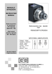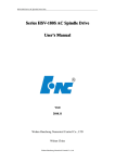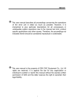
1
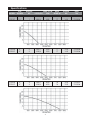
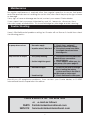
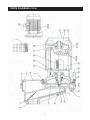
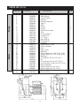
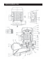
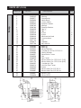
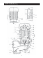
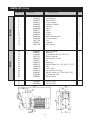
CPE RANGE PUMPS MODEL NO: CPE15S/T-20S/T-30S/T PART No: 7120203/4-7120205/6-7120207/8 OPERATION & MAINTENANCE INSTRUCTIONS 1002 Contents Specifications .................................................................................. 2 Guarantee : .................................................................................... 3 Safety Precautions .......................................................................... 4 Water Connections ........................................................................ 5 Electrical Connection : .................................................................. 6 Maintenance : ................................................................................ 7 Trouble Shooting ............................................................................. 7 Parts (CPE15) : ......................................................................... 9 & 10 Parts (CPE20) : ....................................................................... 11 & 12 Parts (CPE30) : ....................................................................... 13 & 14 We delare that this product complies with the 73/23/EEC directive. Please note that the details and specifications contained herein are correct at the time of going to print. However CLARKE International reserve the right to change specifications at any time without prior notice. Always consult the machines data plate -1- Specifications MODEL SIZE INCHES MOTOR HP VOLTS/PH MAX FLOW MAX LPM HEAD M CPE15S CPE15T 1½” 1½” 1 1 230/1 400/3 325 325 CPE20S CPE20T 2” 2” 2 2 230/1 400/3 CPE30S CPE30T 3” 3” 3 3 230/1 400/3 -2- WEIGHT KG PART No 17 17 14.0 14.0 7120203 7120204 500 500 17 17 14.5 14.5 7120205 7120206 800 800 18 18 15.5 15.5 7120207 7120208 Please read these instructions carefully before operating the Pump Thank you for purchasing this CLARKE Pump Before using the device, please read this manual thoroughly and carefully follow all instructions given. This is for your own safety and that of others around you, and is also to help you achieve long and trouble free service from your new tool. CLARKE GUARANTEE This CLARKE product is guaranteed against faulty manufacture for a period of 12 months from the date of purchase. Please keep your receipt as proof of purchase. This guarantee is invalid if the product is found to have been abused or tampered with in any way, or not used for the purpose for which it was intended. Faulty goods should be returned to their place of purchase, no product can be returned to us without prior permission. This guarantee does not affect your statutory rights. Your CLARKE CPE PUMP is a highly efficient, robust, continuously rated, self priming pump with a powerful electric motor, and is ideal for a wide range of domestic, commercial and agricultural uses. It is suitable for pumping clean tap and rain water , and will handle small solids in suspension. Your CLARKE CPE PUMP is designed to give you trouble free service provided it is installed and used in the correct way. Please follow these instructions carefully. WARNING CPE RANGE PUMPS ARE NOT SUBMERSIBLE PUMPS. ON NO ACCOUNT MUST THEY BE IMMERSED IN WATER. if the pump is left in an exposed position, it should be protected from the elements. especially frost. All electrical connections should be inspected regularly for signs of corrosion and cleaned where necessary. It is advisable to apply a film of silicon grease on the terminals for added protection. -3- Safety Precautions WARNING: As with all machinery, there are certain hazards involved with their operation and use. Exercising respect and caution will considerably lessen the risk of personal injury. However, if normal safety precautions are overlooked or ignored, personal injury to the operator even damage to the pump or property, may result. For your own safety and that of others around you, please read these safety instructions in conjunction with the operating instructions, and before using the pump. These pumps are designed to pump Water Only. NEVER use for pumping flammable liquids or chemicals of any kind. ALWAYS ensure the pump is installed in a horizontal position with the outlet facing vertically upwards, and that it is firmly anchored via its fixing screws. ALWAYS ensure there is an adequate air flow around the pump. DO NOT mount it in an enclosed atmosphere. ALWAYS ensure all water pipes - supply or discharge, are adequately supported where necessary, so as not to put a strain on the pump connections. ALWAYS ensure the inlet to the pump is completely unrestricted. ALWAYS ensure the pump is protected from the elements, neither the motor nor the electrical terminal box is intended to be waterproof. ALWAYS ensure that all pipes are protected against damage where necessary, and that they are suitably lagged to avoid the possibility of freezing during cold weather. ALWAYS disconnect the pump from the electrical supply before any cleaning or maintenance of the pump. NEVER allow the pump to run dry, as this will cause serious damage to the pump seals. NEVER switch the pump ON when a swimming pool etc, is in use, i.e., when there is person or animal in the pool. -4- Water Connections IMPORTANT: The pump MUST NOT be connected to the mains supply until all hose/pipe installation is completed. DO NOT RUN THE PUMP DRY NOTE: If any part of the system is to be connected to the mains water supply, ensure that local water authority regulations are observed. Because of the variety of possible installations, no plumbing accessories are supplied with your pump, however accessories designed specifically for this range of pumps is available from your nearest CLARKE dealer. The pump must always be installed and operated in an upright position i.e. with the outlet port facing vertically upwards. The fixing holes in the base should be used as necessary to secure the pump firmly in it operating position. Also ensure there is adequate air circulation around the motor. Avoid situations where there is a risk of water coming into contact with the outside of the pump. Neither the motor or the terminal box are designed to be waterproof. Fig. 1 These notes are for guidance on how to achieve a proper working system. The diagram (Fig. 1) above shows a typical installation at the pump. A foot valve and filter should be fitted to the lower end of the suction hose, as illustrated in Fig. 2, so as to retain water in the suction system and more importantly, to prevent the possibility of large foreign objects entering the pump body. The performance of your pump will be affected by the diameter of the inlet pipe - any restriction will greatly reduce the flow. We strongly recommend that you use a pipe diameter as large as practicable. A gate valve may be installed in-line on the delivery side (Outlet Port) of the pump which can be adjusted as required to regulate the flow of water, it can also assist in priming the pump. WARNING DO NOT place any such obstruction on the suction side (inlet Port) of the pump unless it is an isolator valve in a gravity fed system. It is also IMPORTANT to note, that these pumps should not be operated with the delivery valve completely closed. To prevent unnecessary strain or possible distortion to the pump, ensure that adequate support is provided to the hoses and or pipes. They will be considerably heavier when filled with water. Filter Foot Valve Fig. 2 Should foreign contaminants come into contact with the pump, flush through with cold water as soon as possible to prevent damage to the pump. Protect the pump and pipework from freezing. The formation of ice may cause serious damage. Where the pump is to be a permanent fixture, the fittings to the pump MUST be flexible, i.e. a short piece of hose should be inserted between the rigid pipework and the pump. -5- Electrical Connection WARNING: THIS PUMP MUST BE EARTHED. Before connecting the pump, check the voltage and phase supply required, this information can be found on the junction box cover on top of the motor. Installation should be carried out by a qualified electrician, using I.E.E approved cable and fittings, and in accordance with I.E.E. Regulations. However, in the further interests of safety we would emphasise the following, Wiring Connections For Single Phase Models Single phase pumps should be connected to a standard domestic 13 amp, 230 volt (50Hz), electrical supply, we strongly recommend that the connection be made via a suitable isolator switch and Residual Current Device (RCD). IMPORTANT: Should the supply be taken from a normal 13 amp socket, then the plug used must be to BS 1363 standard, and the wires should be wired up in accordance with the following colour code: Green & Yellow ............... Earth or marked with a letter “E” or Earth symbol “ ”. Blue ................................... Neutral or terminal marked with a letter “N” Brown ............................... Live or terminal marked with a letter “L” Connections InsideTerminal Box Wiring Connections For Three Phase Models Again installation should be carried out by a qualified electrician, using I.E.E cable and fittings, and in accordance with I.E.E Regulations. To connect the cable to the motor see electrical connections inside the terminal cover. Delta Connection L1 L2 Star Connection L3 L1 L2 L3 IF IN ANY DOUBT, contact CLARKE International Service on 020 8988 7400 -6- Maintenance No regular maintenance is required other than regular inspection to ensure that leaves and other particles are not covering the suction inlet, also check the pump for signs of wear or damage. If any signs of wear or damage are found, contact your nearest Clarke dealer. If you suspect that your pump is blocked by mud, silt , leaves etc, disconnect from the mains supply and backflush. This should dislodge any blockage and aid cleaning. Trouble Shooting there is little likelihood of problems arising, but if water will not flow as it should then check the following points:- The pump does not run 1. No mains supply 2. Impeller seized / blocked Pump runs but no output 1. Air in pump housing 2. Suction height too great Low or no Flow 1. Blocked inlet pipe 2. Head too high 1. Check fuse - replace if necessary (Check fuse rating). 2. Disconnect pump from mains, investigate cause and clear blockage etc.. 1. Disconnect from the mains and check all hose connections are air tight etc. 2. Check height is within spec. for your pump, (see specs page 2). 1. Check to see that no foreign matter is fouling the intake system and check the filter is not blocked or obstructed. 2. Check that head is within spec. Should you still experience problems, then contact your Clarke dealer, or CLARKE International Service Department for advice. PARTS & SERVICE TEL: 020 8988 7400 or e-mail as follows: PARTS: [email protected] SERVICE: [email protected] -7- PARTS DIAGRAM (CPE15) -9- PARTS LIST (CPE15) Index No Motor Pump 1 2 3 4 5 6 7 8 9 10 11 12 13 14 15 16 17 18 19 20 21 22 23 24 25 26 27 28 29 30 31 32 33 34 Part No GM1076 GM5853 GM6010 GM6162 GM6186 GM6209 GM6213 GM6230 GM6268 GM6334 GM7103 GM7702 GM7776 GM8048 GMF156 GMF458 GMF501 GM5114 GM5119 GM5293 GM5319 GM5375 GM5387 GM5493 GM5513 GM6581 GM6764 GM6963 GM7259 GM7700 GM8640 GM8641 GMF313 GMF490 Description Connection 1½” x 40 Valve Body Check Valve Washer Flexolite Washer Tap ¼” Tap 1” Screw Screw Mechanical Seal Nut Counterface Cover Disk ‘O’ Ring Key 4x4x16 Pump Body Impeller Rear motor Cover Elastic Washer Fan Fan Cover Bearing Motor Stator For CPE 15 A1 (1HP) Motor Stator For CPE 15 A3 (3HP) Bearing Condenser 20 For CPE 15 A1 Vis Condenser Box For CPE 15 A1 junction Box Cover For CPE 15 A3 Motor Bracket Motor Shaft For CPE 15 A1 Motor Shaft For CPE 15 A3 Motor (1PH) Motor (3PH) -10- Qty 1 1 1 1 1 1 1 6 8 1 1 1 1 1 1 1 1 1 1 1 1 1 1 1 1 1 4 1 1 1 1 1 1 1 PARTS DIAGRAM (CPE20) -11- PARTS LIST (CPE20) Index No Qty Pump Description 2 3 4 5 6 7 8 9 10 11 12 13 14 15 16 17 GM1010 GM5342 GM5571 GM5854 GM6012 GM6029 GM6162 GM6186 GM6209 GM6213 GM6235 GM6236 GM6334 GM6346 GM7103 GM8612 GMF156 Connection 2” x 50 Washer Pump Body Valve Body Check Valve Flexolite Gasket Washer Flexolite Washer Tap ¼” Tap 1” Screw Screw Mechanical Seal Counterface Nut Impeller Key 4x4x16 2 1 1 1 1 1 1 1 1 1 4 6 1 1 1 1 1 Motor 1 Part No 18 19 20 21 22 23 24 25 26 27 28 29 30 31 32 GM5465 GM5466 GM5503 GM6994 GM6996 GM6997 GM6998 GM6999 GM7168 GM7176 GM8002 GM8018 GM8084 GM8643 GM8650 Bearing Bearing Motor Bracket Condenser 30 For CPE 20 A1 Elastic Washer Rear Motor Cover Fan Fan Cover Motor Stator For CPE 20 A1 (1HP) Motor Stator For CPE 20 A3 (3HP) Condenser Clip junction Box Cover Screw Motor Shaft For CPE 20 A1 Motor Shaft For CPE 20 A3 1 1 1 1 1 1 1 1 1 1 1 1 4 1 1 33 34 GM8657 GM8658 Motor (1PH) Motor (3PH) 1 1 -12- PARTS DIAGRAM (CPE30) -13- PARTS LIST (CPE30) Motor Pump Index No Part No Description Qty 1 2 3 4 5 6 7 8 9 10 11 12 13 14 15 GM5342 GM5574 GM5857 GM6013 GM6029 GM6162 GM6209 GM6211 GM6235 GM6261 GM6334 GM6346 GM7103 GM8613 GMF156 Washer Pump Body Valve Body Check Valve Flexolite Gasket Washer Tap ¼” Tap 1” Screw Screw Mechanical Seal Counterface Nut Impeller Key 4x4x16 1 1 1 1 1 1 1 1 4 6 1 1 1 1 1 16 17 18 19 20 21 22 23 24 25 26 27 28 29 GM5505 GM6321 GM6854 GM7187 GM8010 GM8011 GM8013 GM8014 GM8016 GM8017 GM8018 GM8052 GM8286 GM8652 Motor Bracket Bearing Condenser 50 For CPE 30 A1 Elastic washer Rear Motor Cover Vis Bearing Motor Stator For CPE 30 A1 (1 HP) Fan Fan Cover Junction Box Cover Motor stator For CPE 30 A3 (1PH) Condenser Clip Motor Shaft 1 1 1 1 1 4 1 1 1 1 1 1 1 1 30 31 GM8659 GM8660 Motor (1PH) Motor (3PH) 1 1 -14-