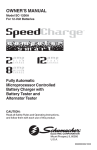
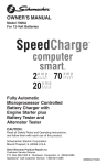
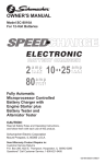
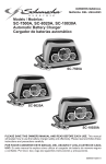
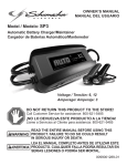
1
1.3
To reduce the risk of damage to the electric plug or cord, pull by the plug
rather than the cord when disconnecting the charger.
1.4
An extension cord should not be used unless absolutely necessary. Use of
an improper extension cord could result in a risk of fire and electric shock. If
an extension cord must be used, make sure:
•That the pins on the plug of the extension cord are the same size and
shape as those of the plug on the charger.
•That the extension cord is properly wired and in good electrical
condition.
•That the wire size is large enough for the AC ampere rating of the
charger as specified in Section 8.3.
1.5
To reduce the risk of electric shock, unplug the charger from the outlet
before attempting any maintenance or cleaning.
1.6
Remove personal metal items such as rings, bracelets, necklaces and
watches when working with a lead-acid battery. A lead-acid battery can produce a short-circuit current high enough to weld a ring or the like to metal,
causing a severe burn.
1.7
Do not operate the charger with a damaged cord or plug; take it to a qualified service person. (Call customer service at: 1-800-621-5485.)
1.8
Do not operate the charger if it has received a sharp blow, been dropped or
otherwise damaged in any way; take it to a qualified service person. (Call
customer service at: 1-800-621-5485.)
1.9
Do not disassemble the charger; take it to a qualified service person when
service or repair is required. Incorrect reassembly may result in a risk of fire
or electric shock. (Call customer service at: 1-800-621-5485.)
Model SC-200A & SCF-200A
Automatic Battery Charger
Voltage: 6, 12
Amperage: 2, 4
2.
OWNER’S MANUAL
•
READ THE ENTIRE MANUAL BEFORE USING THIS
PRODUCT. FAILURE TO DO SO CAN RESULT IN
SERIOUS INJURY OR DEATH.
Risk of explosive gases.
00-99-000973-0609
2.1
Working in the vicinity of a lead-acid battery is dangerous. Batteries generate explosive gases during normal battery operation. For this reason, it is
of utmost importance that you follow the instructions each time you use the
charger.
2.2
To reduce the risk of a battery explosion, follow these instructions and those
published by the battery manufacturer and the manufacturer of any equipment you intend to use in the vicinity of the battery. Review the cautionary
markings on these products and on the engine.
2.3
NEVER smoke or allow a spark or flame in the vicinity of a battery or engine.
2.4
Be extra cautious to reduce the risk of dropping a metal tool onto the battery. It might spark or short-circuit the battery or other electrical part that
may cause an explosion.
2.5
Use this charger for charging LEAD-ACID batteries only. It is not intended to
supply power to a low voltage electrical system other than in a starter-motor
application. Do not use this battery charger for charging dry-cell batteries
that are commonly used with home appliances. These batteries may burst
and cause injury to persons and damage to property.
2.6
NEVER charge a frozen battery.
2.7
NEVER overcharge a battery.
IMPORTANT: READ AND SAVE THIS SAFETY AND INSTRUCTION MANUAL.
SAVE THESE INSTRUCTIONS – The SC-200A and SCF-200A offer a wide
range of features to accommodate your needs. This manual will show you how
to use your charger safely and effectively. Please read, understand and follow
these instructions and precautions carefully, as this manual contains important
safety and operating instructions. The safety messages used throughout this
manual contain a signal word, a message and an icon.
The signal word indicates the level of the hazard in a situation.
Indicates an imminently hazardous situation which, if not avoided,
will result in death or serious injury to the operator or bystanders.
Indicates a potentially hazardous situation which, if not avoided,
could result in death or serious injury to the operator or
bystanders.
Indicates a potentially hazardous situation which, if not avoided,
could result in moderate or minor injury to the operator or
bystanders.
3.
Indicates a potentially hazardous situation which, if not avoided,
could result in damage to the equipment or vehicle or property
damage.
The icon gives a graphical description of the potential hazard.
Pursuant to California Proposition 65, this product contains chemicals known to the State of California to cause cancer and birth
defects or other reproductive harm.
3.1
Consider having someone close enough by to come to your aid when you
work near a lead-acid battery.
3.2
Have plenty of fresh water and soap nearby in case battery acid contacts
your skin, clothing or eyes.
3.3
Wear complete eye and body protection, including safety goggles and protective clothing. Avoid touching your eyes while working near the battery.
3.4
If battery acid contacts your skin or clothing, immediately wash the area with
soap and water. If acid enters your eye, immediately flood the eye with cold
running water for at least 10 minutes and get medical attention right away.
3.5
If it is necessary to remove the battery from the vehicle to charge it, always
remove the grounded terminal first. Make sure all of the accessories in the
vehicle are off to prevent arcing.
3.6
Be sure the area around the battery is well ventilated while the battery is
being charged.
3.7
Clean the battery terminals before charging the battery. During cleaning,
keep airborne corrosion from coming into contact with your eyes, nose and
mouth. Use baking soda and water to neutralize the battery acid and help
eliminate airborne corrosion. Do not touch your eyes, nose or mouth.
3.8
Add distilled water to each cell until the battery acid reaches the level specified by the battery manufacturer. Do not overfill. For a battery without removable cell caps, such as valve regulated lead acid batteries (VRLA), carefully
follow the manufacturer’s recharging instructions.
IMPORTANT SAFETY INSTRUCTIONS
Risk of electric shock or fire.
1.1
Do not expose the charger to rain or snow.
1.2
Use only recommended attachments. Use of an attachment not recommended or sold by Schumacher® Electric Corporation may result in a risk of
fire, electric shock or injury to persons or damage to property.
PREPARING TO CHARGE
Risk of contact with battery acid. Battery acid is a
highly corrosive sulfuric acid.
Safety messages in this manual contain two different type styles.
•Unnumbered type states the hazard.
•Numbered type states how to avoid the hazard.
1.
PERSONAL PRECAUTIONS
1
3.9
Read, understand and follow all instructions for the charger, battery, vehicle
and any equipment used near the battery and charger. Study all of the battery manufacturer’s specific precautions while charging and recommended
rates of charge.
7.2
Attach at least a 24-inch (61 cm) long 6-gauge (AWG) insulated battery
cable to the NEGATIVE (NEG, N, -) battery post.
7.3
3.10
Determine the voltage of the battery by referring to the vehicle owner’s
manual and make sure that the output voltage of the charger is the correct
voltage.
Connect the POSITIVE (RED) charger clip to the POSITIVE (POS, P, +)
post of the battery.
7.4
3.11
Make sure that the charger cable clips make tight connections.
Position yourself and the free end of the cable you previously attached to
the NEGATIVE (NEG, N, -) battery post as far away from the battery as possible – then connect the NEGATIVE (BLACK) charger clip to the free end of
the cable.
7.5
Do not face the battery when making the final connection.
7.6
Connect the AC supply cord to the electrical outlet.
7.7
When disconnecting the charger, always do so in the reverse order of the
connecting procedure and break the first connection while as far away from
the battery as practical.
7.8
A marine (boat) battery must be removed and charged on shore. To charge
it onboard requires equipment specially designed for marine use.
4.
CHARGER LOCATION
Risk of explosion and contact with
battery acid.
4.1
Locate the charger as far away from the battery as the DC cables permit.
4.2
Never place the charger directly above the battery being charged; gases
from the battery will corrode and damage the charger.
4.3
Do not set the battery on top of the charger.
4.4
Never allow battery acid to drip onto the charger when reading the electrolyte specific gravity or filling the battery.
4.5
Do not operate the charger in a closed-in area or restrict the ventilation in
any way.
4.6
This charger employs parts, such as switches and circuit breakers, that
tend to produce arcs and sparks. If used in a garage, locate this charger 18
inches (45.72 cm) or more above floor level.
5.
Connect and disconnect the DC output clips only after setting all of the
charger switches to the “off” position and removing the AC plug from the
electrical outlet. Never allow the clips to touch each other.
5.2
Attach the clips to the battery and chassis, as indicated in steps 6.5, 6.6,
7.2, 7.3 and 7.4.
BATTERY CHARGING – AC CONNECTIONS
Risk of electric shock or fire.
DC CONNECTION PRECAUTIONS
5.1
6.
8.
FOLLOW THESE STEPS WHEN BATTERY IS INSTALLED IN
VEHICLE.
8.1
This battery charger is for use on a nominal 120-volt circuit. The charger
must be grounded to reduce the risk of electric shock. The plug must be
plugged into an outlet that is properly installed and grounded in accordance
with all local codes and ordinances. The plug pins must fit the receptacle
(outlet). Do not use with an ungrounded system.
8.2
Never alter AC cord or plug provided – if it does not fit the outlet, have
proper grounded outlet installed by a qualified electrician. Improper connection can result in a risk of an electric shock or electrocution. NOTE: The use
of an adapter plug is not recommended.
8.3
Recommended minimum AWG size for extension cord:
•100 feet long or less - use an 18 gauge extension cord.
•Over 100 feet long - use a 16 gauge extension cord.
9.
FEATURES
A spark near the battery may cause
a battery explosion. To reduce the
risk of a spark near the battery:
7
6
1
5
6.1
Position the AC and DC cables to reduce the risk of damage by the hood,
door and moving or hot engine parts. NOTE: If it is necessary to close the
hood during the charging process, ensure that the hood does not touch the
metal part of the battery clips or cut the insulation of the cables.
6.2
Stay clear of fan blades, belts, pulleys and other parts that can cause injury.
6.3
Check the polarity of the battery posts. The POSITIVE (POS, P, +) battery
post usually has a larger diameter then the NEGATIVE (NEG, N, -) post.
6.4
Determine which post of the battery is grounded (connected) to the chassis.
If the negative post is grounded to the chassis (as in most vehicles), see
step 6.5. If the positive post is grounded to the chassis, see step 6.6.
6.5
For a negative-grounded vehicle, connect the POSITIVE (RED) clip from the
battery charger to the POSITIVE (POS, P, +) ungrounded post of the battery.
Connect the NEGATIVE (BLACK) clip to the vehicle chassis or engine block
away from the battery. Do not connect the clip to the carburetor, fuel lines or
sheet-metal body parts. Connect to a heavy gauge metal part of the frame
or engine block.
6.6
Connect the AC supply cord to the electrical outlet.
6.8
When disconnecting the charger, turn all switches to off, disconnect the AC
cord, remove the clip from the vehicle chassis and then remove the clip from
the battery terminal.
6.9
7.
2. CHECK BATTERY
3. CHARGING
4. CHARGED
2
(red) LED
(yellow) LED
(green) LED
6. Ring Terminal Cable Assembly
7. 12V Plug Cable Assembly
10.
ASSEMBLY INSTRUCTIONS
No assembly required
11.
CONTROL PANEL
The charger does not have an ON/OFF switch. The On and Off commands are
controlled by plugging the charger into a 120V AC electrical wall outlet only
after the battery connections have been made and the Amp/Volt selector switch
has been set.
See CALCULATING CHARGE TIME for length of charge information.
FOLLOW THESE STEPS WHEN BATTERY IS OUTSIDE
VEHICLE.
11.1
Amp/Volt Selector Switch
2 Amp, 12 Volt
A spark near the battery may cause
a battery explosion. To reduce the
risk of a spark near the battery:
7.1
4
5. Battery Clip Cable Assembly
For a positive-grounded vehicle, connect the NEGATIVE (BLACK) clip from
the battery charger to the NEGATIVE (NEG, N, -) ungrounded post of the
battery. Connect the POSITIVE (RED) clip to the vehicle chassis or engine
block away from the battery. Do not connect the clip to the carburetor, fuel
lines or sheet-metal body parts. Connect to a heavy gauge metal part of the
frame or engine block.
6.7
3
1. Amp/Volt Selector Switch
4 Amp, 6 Volt
Check the polarity of the battery posts. The POSITIVE (POS, P, +) battery
post usually has a larger diameter than the NEGATIVE (NEG, N, -) post.
2
11.2
LED Display
Battery Connection Indicator
If the charger does not detect a properly connected battery, the CHECK BAT-
CHECK BATTERY
(red) LED lit: Indicates the battery is not properly
connected to the charger.
TERY
CHECK BATTERY
mode.
Completion of Charge
(green) LED. When
Charge completion is indicated by the CHARGED
lit, the charger has stopped charging and switched to the Maintain Mode of
operation.
CHARGING
battery.
(red) LED blinking: Indicates the charger is in abort
(yellow) LED lit: Indicates the charger is charging the
(red) LED is on..
Maintain Mode (Float-Mode Monitoring)
(green) LED is lit, the charger has started Maintain
When the CHARGED
Mode. In this mode, the charger keeps the battery fully charged by delivering a
small current when necessary. If the battery voltage drops below a preset level,
the charger will go back into Charge Mode until the battery voltage returns to
the full charge level, at which point the charger will return to Maintain Mode.
The voltage is maintained at a level determined by the 6 volt or 12 volt battery
type selected.
CHARGED
(green) LED lit: Indicates the battery is fully charged and the
charger is in maintain mode.
NOTE: See the Operating Instructions section for a complete description of the
charger modes.
12.
(red) LED will light continuously until such a battery is detected.
Charging will not begin while the CHECK BATTERY
OPERATING INSTRUCTIONS
Charging
NOTE: The charger automatically switches between Charge Mode and
Maintain Mode as necessary. The CHARGED
(green) LED will cycle on
when the battery is at full charge and off when the voltage drops below a preset
level and the charger goes into Charge Mode. This cycle will continue, and the
CHARGED
(green) LED will stay on for longer periods of time as the battery becomes more fully charged.
1. Ensure that all of the charger components are in place and in good
working condition, including the plastic boots on the battery clips.
2. Connect the battery following the connection instructions described in
Using the Quick-Disconnect Cable Connectors section.
3. Set the Amp/Volt Selector Switch to the proper setting for the battery
being charged.
Desulfation Mode
If the battery is left discharged for an extended period of time, it could become
sulfated and not accept a normal charge. If the charger detects a sulfated
battery, the charger will switch to a special mode of operation designed for
such batteries. If successful, normal charging will resume after the battery is
desulfated. Desulfation could take up to 8 hours. If desulfation fails, charging
4. Connect the AC power following the precautions listed in Section 8.
5. If you’ve connected everything correctly, the CHARGING
(yellow)
LED should be lit indicating that the charger is charging. If the CHARGING
(yellow) LED does not light or if the CHECK BATTERY
(red) LED is lit, check the connections or have the battery checked/
replaced.
(red) LED will blink.
will abort and the CHECK BATTERY
NOTE: This charger is equipped with an auto-start feature. It will not supply
current to the battery clips until a battery is properly connected. Unlike traditional chargers, the clips will not spark if touched together.
Aborted Charge
If charging can not be completed normally, charging will abort. When charging
aborts, the charger’s output is shut off, and the CHECK BATTERY
(red)
LED will blink. To reset after an aborted charge, either disconnect the battery or
unplug the charger.
USING THE QUICK-DISCONNECT CABLE CONNECTORS
Connect any of the three output cable assemblies to the charger in seconds.
Make sure to place the charger on a dry, non-flammable surface like metal or
concrete.
13.
CALCULATING charge times
This charger adjusts the charging time in order to charge the battery completely, efficiently and safely.
NOTE: Never connect the clamp and ring terminal connectors together for use
in other applications, such as external battery or other power source charging,
or to extend the output cable length, as reverse polarity and/or overcharge
conditions will occur.
This battery charger has a rated output of 2 and 4 amperes. This output will
vary with the age and condition of the battery being charged. If the battery has
only been slightly discharged, it can be charged in less than a few hours. The
same battery will take longer to charge if it is very weak.
50 amp Battery Clips
1. Connect the end of the 50 amp battery clips cable Quick-Connect to the
charger.
13.1
Charging Times
2. Follow the steps in sections 6 and 7 to connect the output clips to the
battery.
Battery Condition
3. After a good electrical connection is made to the battery, plug the power
cord into a 3-prong grounded 120V AC electrical wall outlet. Make
sure to place the charger on a dry, non-flammable surface like metal or
concrete.
2 Amp, 12 Volt Battery
Ampere Hour Battery Capacity
Permanent Ring Connectors
The ring connectors permanently attach to the battery providing easy access
to quickly charge your battery. This application is appropriate for motorcycles,
lawn tractors, ATVs and snowmobiles.
50% Discharged
100% Discharged
Approximate Average Charge Time in Hours
10
3.2
12
4.0
7.5
20
6.4
12.4
1. To permanently attach to a battery, loosen and remove each nut from
the bolt at the battery terminal.
6.2
Battery Condition
2. Connect the red POSITIVE ring connector ring to the POSITIVE battery
terminal.
4 Amp, 6 Volt Battery
3. Connect the black NEGATIVE connector ring to the NEGATIVE battery
terminal.
Ampere Hour Battery Capacity
50% Discharged
100% Discharged
Approximate Average Charge Time in Hours
4. Replace and tighten the nuts to secure.
10
1.6
3.2
5. Connect the end of the ring terminal cable Quick-Connect to the charger. Take care to keep the wires and plug away from metal and moving
parts.
12
2.0
4.0
20
3.2
6.4
6. Plug the charger power cord into a 3-prong grounded 120V AC electrical
wall outlet. Make sure to place the charger on a dry, non-flammable
surface like metal or concrete.
14.
12V Accessory Plug
Charge or maintain your battery without lifting the hood.
1. Connect the end of the 12V Accessory Plug Cable Quick-Connect to the
charger.
Before performing maintenance, unplug and disconnect the battery charger
(see Sections 6, 7 and 8).
14.2
After use, unplug the charger and use a dry cloth to wipe all battery corrosion and other dirt or oil from the terminals, cords, and the charger case.
14.3
Ensure that all of the charger components are in place, securely attached
and in good working condition, including the plastic boots on the battery
clips.
14.4
Servicing does not require opening the unit, as there are no user-serviceable parts.
2. Insert the 12V accessory plug into the 12V accessory outlet.
3. Route the power cord from charger through the vehicle’s open window.
4. Plug the charger power cord into a 3-prong grounded 120V AC electrical
wall outlet. Make sure to place the charger on a dry, non-flammable
surface like metal or concrete.
3
MAINTENANCE INSTRUCTIONS
14.1
15.
Store the charger unplugged, in an upright position. The cord will still conduct electricity until it is unplugged from the outlet.
15.2
Store inside, in a cool, dry place (unless you’re using an on-board Marine
Charger).
16.
POSSIBLE CAUSE
REASON/SOLUTION
Charger will not turn on
when properly connected.
AC outlet is dead.
Check for an open fuse or
circuit breaker supplying
the AC outlet.
Poor electrical connection.
Check the power cord
and extension cord for as
loose fitting plug.
Clips are not making a
good connection to the
battery.
Check for poor connection to battery and frame.
Make sure connection
points are clean. Rock
clips back and forth for a
better connection.
Battery is defective.
Have the battery checked.
Reverse connections at
battery.
Unplug the charger and
correct the lead connections.
Transformer laminations
vibrate (buzz).
No problem, this is a
normal condition.
Shorted Diode Assembly
or Output Rectifier Assembly (hum).
Have charger checked by
a qualified technician.
Battery is not properly
connected to the charger.
Make sure the connections from the battery
connector cable to the
battery and to the charger
are tight. Check for a poor
connection to the battery
and the frame. Make sure
the connections points
are clean. Rock the clips
back and forth for a better
connection.
Charger makes a loud
buzz or hum.
CHECK BATTERY
(red) LED is lit.
CHECK BATTERY
(red) LED is blinking.
17.
Manufacturer does not provide any warranty for any accessories used with this
product that are not manufactured by Schumacher Electric Corporation and
approved for use with this product. This Limited Warranty is void
if the product is misused, subjected to careless handling, repaired, or modified
by anyone other than Manufacturer or if this unit is resold through an unauthorized retailer.
TROUBLESHOOTING
PROBLEM
17.1
If your unit is not free from defective material or workmanship, Manufacturer’s
obligation under this warranty is solely to repair or replace your product with a
new or reconditioned unit at the option of the Manufacturer. It is the obligation
of the purchaser to forward the unit, along with mailing charges prepaid to the
Manufacturer or its authorized representatives in order for repair or replacement to occur.
STORAGE INSTRUCTIONS
15.1
Reverse connections at
battery.
Unplug the charger and
correct the lead connections.
Charger is in abort mode.
See “Aborted Charge”
in the OPERATING INSTRUCTIONS Section.
Manufacturer makes no other warranties, including, but not limited to, express,
implied or statutory warranties, including without limitation, any implied warranty of merchantability or implied warranty of fitness for a particular purpose.
Further, Manufacturer shall not be liable for any incidental, special or consequential damage claims incurred by purchasers, users or others associated
with this product, including, but not limited to, lost profits, revenues, anticipated
sales, business opportunities, goodwill, business interruption and any other
injury or damage. Any and all such warranties, other than the limited warranty
included herein, are hereby expressly disclaimed and excluded. Some states
do not allow the exclusion or limitation of incidental or consequential damages
or length of implied warranty, so the above limitations or exclusions may not
apply to you. This warranty gives you specific legal rights and it is possible you
may have other rights which vary from this warranty.
THIS LIMITED WARRANTY IS THE ONLY EXPRESS LIMITED WARRANTY
AND THE MANUFACTURER NEITHER ASSUMES OR AUTHORIZES ANYONE TO ASSUME OR MAKE ANY OTHER OBLIGATION TOWARDS THE
PRODUCT OTHER THAN THIS WARRANTY.
Schumacher Electric Corporation Customer Service
1-800-621-5485
Monday – Friday 7:00 a.m. to 5:00 p.m. CST
Schumacher and the Schumacher Logo are registered trademarks of
Schumacher Electric Corporation
Modelo SC-200A & SCF-200A
Cargador de Baterías Automático
MANUAL DEL usuario
•
BEFORE RETURNING FOR REPAIRS
When a charging problem arises, make certain that the battery is capable of
accepting a normal charge. Use a good battery to double check all connections, the AC outlet for a full 120-volts, the charger clips for correct polarity
and the quality of the connections from the cables to the clips and from the
clips to the battery system. The clips must be clean.
17.2
When a battery is very cold, partially charged or sulfated, it will not draw
the full rated amperes from the charger. It is both dangerous and damaging
to a battery to force higher amperage into it than it can effectively use in
recharging.
17.3
When an UNKNOWN OPERATING PROBLEM arises, please read the
complete manual and call the customer service number for information that
will usually eliminate the need for return.
LEA EL MANUAL COMPLETO ANTES DE UTILIZAR ESTE
PRODUCTO. CUALQUIER FALLA PODRÍA RESULTAR EN
SERIAS LESIONES O PODRÍA SER MORTAL.
IMPORTANTE: LEA Y GUARDE ESTE MANUAL DE INSTRUCCIONES Y
SEGURIDAD.
GUARDE ESTAS INSTRUCCIONES: los SC-200A and SCF-200A ofrecen una
amplia gama de características para satisfacer sus necesidades. Este manual
le mostrará cómo utilizar su cargador en forma segura y efectiva. Por favor,
lea, comprenda y siga estas instrucciones y precauciones cuidadosamente, ya
que este manual contiene instrucciones operativas y de seguridad de importancia. Los mensajes de seguridad representados en este manual contienen
palabras guía, un mensaje y una figura.
La palabra guía indica el nivel de peligro en determinada situación.
If the above solutions do not eliminate the problem or for
information about troubleshooting or replacement parts,
call toll-free from anywhere in the U.S.A.
1-800-621-5485
7:00 am to 5:00 pm Central Time Monday thru Friday
18.
REPLACEMENT PARTS
Battery Clip Cable Assembly-----------------------------------------38-99-001235
PELIGRO
Indica una inminente situación de riesgo que, si no se evita, resultaría mortal o de serios perjuicios al operador o personas alrededor.
ADVERTENCIA
Indica una situación potencialmente riesgoso que, si no se evita,
podría resultar o de serios perjuicios al operador o
personas alrededor.
ATENCIÓN
Indica una situación potencialmente peligrosa que, de no evitarse,
podría resultar en menores o serio daños al usuario y terceras
personas.
Ring Terminal Cable Assembly--------------------------------------38-99-001233
IMPORTANTE
12V Plug Cable Assembly--------------------------------------------38-99-001401
19.
Indica una situación potencialmente peligrosa que, de no evitarse,
podría causar daño al equipo, al vehículo y propiedades alrededor.
Los mensajes estipulados en este manual se describen dos tipos de estilo.
•Los que aparecen sin número indican el riesgo.
•Aquellos que aparecen numerados, indican cómo evitar los riesgos.
LIMITED WARRANTY
SCHUMACHER ELECTRIC CORPORATION, 801 BUSINESS CENTER
DRIVE, MOUNT PROSPECT, IL 60056-2179, MAKES THIS LIMITED WARRANTY TO THE ORIGINAL RETAIL PURCHASER OF THIS PRODUCT. THIS
LIMITED WARRANTY IS NOT TRANSFERABLE OR ASSIGNABLE.
Schumacher Electric Corporation (the “Manufacturer”) warrants this battery
charger for 2 years from the date of purchase at retail against defective material or workmanship that may occur under normal use and care.
Voltios: 12
Amperios: 2, 4
La figura muestra una descripción gráfica del potencial de riesgo.
4