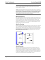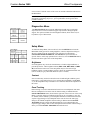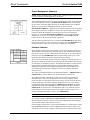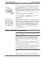
1
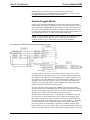
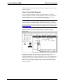
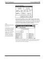
This document was prepared and written by the Technical Documentation department at: Crestron Electronics, Inc. 15 Volvo Drive Rockleigh, NJ 07647 1-888-CRESTRON Crestron Series 1600 Wired Touchpanels Contents Series 1600 Wired Touchpanels 1 Description................................................................................................................................. 1 Functional Description ................................................................................................ 1 Physical Description.................................................................................................... 2 Model Differences ....................................................................................................... 3 Leading Specifications............................................................................................................... 4 Installation/Setup ....................................................................................................................... 5 Identity Code ............................................................................................................... 5 Recommended Cleaning.............................................................................................. 5 Network Wiring........................................................................................................... 5 Hardware Hookup ....................................................................................................... 6 Configuring the Touchpanel ...................................................................................................... 8 Calibration Menu......................................................................................................... 8 Diagnostics Menu........................................................................................................ 9 Setup Menu.................................................................................................................. 9 SIMPL™ Windows Programming......................................................................................... 11 How the Program Works ........................................................................................... 12 How to Create the Program ....................................................................................... 13 Reserved Join Numbers............................................................................................. 16 Problem Solving ...................................................................................................................... 16 Troubleshooting......................................................................................................... 16 Further Inquiries ........................................................................................................ 17 Future Updates .......................................................................................................... 17 Appendix A: RS-232 Protocol................................................................................................. 18 Appendix B: Cutout Detail of Supplied Template................................................................... 20 Software License Agreement................................................................................................... 21 Return and Warranty Policies .................................................................................................. 23 Merchandise Returns / Repair Service ...................................................................... 23 CRESTRON Limited Warranty................................................................................. 23 Operations & Installation Guide - DOC. 5836A SeriesSeries 1600 Wired Touchpanels • i Crestron Series 1600 Wired Touchpanels Series 1600 Wired Touchpanels Description Functional Description The Series 1600 Touchpanels are 5.7-inch (14.4-cm) touchscreen control panels for any Crestron remote control system (herein referred to as the control system). There are six Series 1600 models available. Options are color versus grayscale, adjustable tiltcase versus lectern/wall mount, and “Designer Series” color cover. Model selection is based on application requirements. Refer to "Model Differences" on page 3 for a more detailed description of each. The purpose of the Series 1600 Touchpanel is to replace large, complicated panels with a series of simpler screens, each specific to the control problem at hand. Thus, very large numbers of functions can be made available to the user without the confusion associated with hardware panels of that complexity. Series 1600's icons, graphics, and text can dramatically increase any user's comprehension of the control environment. Devices, functions, and control zones are quickly organized and more easily accessed. The Series 1600 Touchpanels offer: • 256 color passive matrix display (color models only) • 4 shades of grayscale FSTN transmissive mode display (grayscale models only) • pop-up sub panels to reduce memory requirements, providing optimal speed and performance • multiple button, slider control, and icon configurations • up to 999 functions and 96 screens • fast graphics performance: imported photographs, drawings, and icons • support for downloadable fonts - proportional and non-proportional • foreign language text • Position Lock feature provides durable support of panel at any angle of inclination between 0 and 70 degrees (tiltcase model only). Operations & Installation Guide - DOC. 5836A SeriesSeries 1600 Wired Touchpanels • 1 Wired Touchpanels Crestron Series 1600 Software Series 1600 color models have one 256-color palette. Therefore, all custom colors are mapped to the nearest color in the standard palette, such that colors from the custom color dialog box may not be exactly represented. If the precise shade is not immediately achieved, the solution is to experiment with a slightly different color from the custom color dialog box in VT Pro-e. VisionTools™ Pro-e (VT Pro-e), a design and programming Windows-based software, permits the creation of control screen variations incorporating two and three-dimensional graphics and text. A set of pages, which make up a project, can be designed for each Series 1600 Touchpanel application. Each page contains objects such as custom control graphics, two and three-dimensional buttons, sliders, and digital readouts which allow the user to interface with the control system. The project is uploaded to the touchpanel and programmed into the flash PROM. The touchpanel uses the programmed project until another set is uploaded from the PC. The PC may be disconnected from the rack or panel except during reprogramming. VT Pro-e also allows users the option to generate projects destined for web browsers rather than for physical touchpanels. For additional software information, consult the VT Pro-e help file. Position Lock Button Hand Position for Tilting Touchpanel to Vertical Hand Position for Tilting Touchpanel to Horizontal The position lock button is centrally located at the front of the base on the Series 1600 adjustable tiltcase model. These touchpanels permit incremental angle positions indicated by audible clicks. Range of motion is adjustable for user comfort and can vary from zero inclination to 70 degrees from horizontal. Thus the user can position the touchscreen to a comfortable angle, just as a microphone can be repositioned for each speaker. The comfortable angle is herein referred to as user position. The position lock guarantees that once a user position is established or locked, the angle will not degrade from repeated presses on the touchscreen. The touchscreen is free to move up from the horizontal to an incremental angle. Grasp the touchscreen with a hand at each side and gently tilt up to a comfortable position. To activate position lock, slightly reverse the motion until the touchpanel stops moving. Correct hand placement is shown to the left. The touchscreen is now set into user position. Once in user position, the position lock button is activated which means the touchscreen can not be forced to the horizontal position without first depressing the button. The touchscreen is still free to tilt up; a new user position is established at each increment or audible click. The position lock button needs to be depressed before the touchscreen can be returned to the horizontal position. To depress the button, slightly position the touchscreen in the vertical direction with two hands, avoiding any tilting. The position lock button can be depressed with one hand; the touchscreen can be tilted down to the horizontal position with the other, shown to the left. Physical Description Tiltcase Model The 5.7-inch (14.4-cm) touch sensitive viewing screen is located on the front of each Series 1600 Touchpanel. The electronic hardware is housed in a high impact, black molded plastic enclosure for the adjustable tiltcase configurations, shown after this paragraph. These tiltcase touchpanels are designed to be placed on a counter and possess a hinged base, which can tilt from 0 to 70 degrees. Depress the button located at the front of the base when pivoting the touchpanel to the horizontal position. A cable with a four-pin network connector at its end is attached to the base of the CT-1600 or LC-1600. Connect the cable directly to the control system. 2 • Series 1600 Wired Touchpanels Operations & Installation Guide - DOC. 5836A Crestron Series 1600 Wired Touchpanels Physical Views of Tiltcase Models CRESTRON Lectern/Wall Mount Model The lectern/wall mount models, shown after this paragraph, are housed in a black metal box topped with a plastic “Designer Series” cover. Mounting hardware is included. The four-pin network port is located on the rear of the panel. Physical Views of Lectern/Wall Mount Models 1.677 in (4.260 cm) 7.635 in (19.393 cm) 6.494 in (16.495 cm) Model Differences There are six Series 1600 models available and selection depends on type of installation (color versus grayscale, adjustable tiltcase versus lectern/wall mount, and “Designer Series” color cover). The prefix and suffix define a model. Refer to the table after this paragraph for a concise listing of Series 1600 touchpanel models. Series 1600 Touchpanel Models MODEL DISPLAY CT-1600 256 Colors LC-1600 4 Shades of Grayscale CT-1600L/W-DB 256 Colors CT-1600L/W-DW 256 Colors LC-1600L/W-DB 4 Shades of Grayscale LC-1600L/W-DW 4 Shades of Grayscale Operations & Installation Guide - DOC. 5836A INSTALLATION "DESIGNER SERIES" Adjustable Tiltcase Adjustable Tiltcase Lectern/Wall Mount Lectern/Wall Mount Lectern/Wall Mount Lectern/Wall Mount Not Applicable Not Applicable Black Cover White Cover Black Cover White Cover SeriesSeries 1600 Wired Touchpanels • 3 Wired Touchpanels Crestron Series 1600 Leading Specifications The table after this paragraph provides a summary of leading specifications for the Series 1600 Touchpanels. Dimensions and weight are rounded to the nearest hundredth unit. NOTE: Check the Crestron FTP site (www.crestron.com) periodically for the latest firmware versions. Search in the TOUCHPNL Library. New users are required to register in order to obtain access to the FTP site. Leading Specifications for Series 1600 Touchpanels SPECIFICATION Power Requirements DETAILS 6 Watts, 24 VDC 0.25 Amp SIMPLTM Windows® Version 1.30.01 or later1 with library update file smwlib62.exe and update document smwlib62.txt or later CNMSX-AV/PRO Upgrade File (.upz) Version 50135X or later2 CNRACKX/-DP Upgrade File (.upz) Version 50700W or later2 CNMS, CNRACK, CNLCOMP Operating System Version 3.18.09m, l, c or later2 ST-CP Operating System Version 4.00.49 or later2 ST-CP Monitor Version 1.29 or later2 TM VisionTools Pro-e (VT Pro-e) Version 2.1.0 or later1 Crestron Database Version 14.01 or later1 Memory 768K Flash for Display CT-1600 & LC-1600 Height: 5.97 in (15.16 cm) Dimensions & Weight Width: 7.67 in (19.48 cm) Depth: 5.32 in (13.51 cm) Weight: 2.82 lb (1.28 kg) CT-, LC-1600L/W-DB & CT-, LC-1600L/W-DW Height: 6.49 in (16.49 cm) Dimensions & Weight Width: 7.64 in (19.39 cm) Depth: 1.68 in (4.26 cm) Weight: 1.71 lb (0.77 kg) View Screen Dimensions Height: 3.52 in (8.94 cm) Width: 4.65 in (11.82 cm) Screen Viewing Angles: CT Models +/-50o for X dir and +40/-50o for Y dir LC Models +/-30o for X dir and +20/-30o for Y dir View Screen Resolution 320 x 240 pixels View Screen LCD: CT Models STN Transmissive color, dot matrix type LC Models FSTN Transmissive mode, dot matrix type View Screen Illumination Edgelit Fluorescent View Screen Touch Screen Resistive Membrane 1 The latest software versions can be obtained from the Downloads page (SIMPLWIN, TOUCHPNL, VTPRO-E, or CRESDB Libraries) of the Crestron website (www.crestron.com). 2 CNX upgrade files are required for either CNMSX-AV/Pro or CNRACKX/-DP. Filenames for CNX upgrade files have a UPZ extension and SmarTouch files are in one EXE. All can be obtained from the Downloads page (OPSYS Library) of the Crestron website. As of the date of manufacture, the unit has been tested and found to comply with specifications for CE marking. NOTE: This device complies with part 15 of the FCC rules. Operation is subject to the following two conditions: (1) this device may not cause harmful interference, and (2) this device must accept any interference received, including interference that may cause undesired operation. 4 • Series 1600 Wired Touchpanels Operations & Installation Guide - DOC. 5836A Crestron Series 1600 Wired Touchpanels Installation/Setup Identity Code Every equipment and user interface within the network requires a unique identity code (NET ID). A two-digit hexadecimal number from 03 to FE is representative of these codes. Refer to "Setup Menu" on page 9 for instructions on setting the unit's NET ID. The NET ID of the unit must match the NET ID specified in the SIMPL Windows program. Refer to "SIMPL™ Windows Programming" on page 11 for a sample. Recommended Cleaning Keep the surface of the touchscreen free of dirt, dust, or other materials that could degrade optical properties. Long term contact with abrasive materials can scratch the surface, which may detrimentally affect image quality. For best cleaning results, use a clean, damp, non-abrasive cloth with any commercially available non-ammonia glass cleaner. Bezels may not provide a complete watertight seal. Therefore, apply cleaning solution to the cloth rather than the surface of the touchscreen. Wipe touchscreen clean and avoid ingress of moisture beneath panels. Network Wiring NOTE: When making four-wire network connections, refer to the latest revision of the Cresnet Network Interconnect Drawing (Doc. 5411). The document can be obtained from the Downloads page (CABLES and MANUAL Libraries) of the Crestron website (www. crestron.com). Search for the CRESNET.PDF files. When calculating the wire gauge for a particular network run, the length of the run and the power factor of each network unit to be connected must be taken into consideration. If network units are to be daisy-chained on the run, the power factor of each network unit to be daisy-chained must be added together to determine the power factor of the entire chain. The length of the run in feet and the power factor of the run should be used in the following resistance equation to calculate the value on the right side of the equation. Resistance Equation R < 40,000 L x PF Where: R = Resistance (refer to table below). L = Length of run (or chain) in feet. PF = Power factor of entire run (or chain). The required wire gauge should be chosen such that the resistance value is less than the value calculated in the resistance equation. Refer to the table after this paragraph. Wire Gauge Values RESISTANCE (R) WIRE GAUGE 4 16 6 18 10 20 Operations & Installation Guide - DOC. 5836A 15 22 13 Doubled CAT5 8.7 Tripled CAT5 SeriesSeries 1600 Wired Touchpanels • 5 Wired Touchpanels Crestron Series 1600 NOTE: All network wiring must consist of two twisted-pairs. One twisted pair is the +24V conductor and the GND conductor and the other twisted pair is the Y conductor and the Z conductor. NOTE: When daisy-chaining Cresnet units, strip the ends of the wires carefully to avoid nicking the conductors. Twist together the ends of the wires that share a pin on the network connector, and tin the twisted connection. Apply solder only to the ends of the twisted wires. Avoid tinning too far up the wires or the end becomes brittle. Insert the tinned connection into the Cresnet connector and tighten the retaining screw. Repeat the procedure for the other three conductors. Hardware Hookup Due to physical differences, the lectern and tiltcase models require different hookup procedures. Furthermore, the lectern model installs simply and cleanly into existing or newly constructed walls (or other suitable mounting surface). Back box and drywall mounting options are available. The stylish, elegant design accommodates painting of its “Designer Series” cover. The necessary mounting hardware (for the drywall option) is provided with each model. Back Box Mounting Back box mounting, shown after this paragraph, is typically used at new construction sites. The optional back box, BB-1600, includes the necessary hardware, brackets, and electrical box, which provides a secure enclosure that, can be fastened directly to the mounting surface. This mounting method is optional and requires the BB-1600 (sold separately). Details for installation are provided in the latest revision of the BB-1600 Installation Guide (Doc. 5835). Back Box Mounting PAN HEAD SCREWS BB-1600 (INSTALLED) TOUCHPANEL COVER DRYWALL Drywall Mounting Each Series 1600 Touchpanel is provided with four metal mounting plates (two small and two large) and eight mounting screws to fasten the panel to a mounting surface without an electrical box. Complete the following installation procedure in the order provided. The only tools required are a pencil (or equivalent), drywall saw (or equivalent), a Phillips tip screwdriver, a drill with a 5/16” bit, and a drill with a #20 bit. Refer to the illustration after this paragraph as needed. 6 • Series 1600 Wired Touchpanels Operations & Installation Guide - DOC. 5836A Crestron Series 1600 Wired Touchpanels Drywall Mounting PAN HEAD SCREWS LARGE MOUNTING PLATE TOUCHPANEL SMALL MOUNTING PLATE COVER DRYWALL 1. Locate an area on the wall clear of studs, wires, and other obstructions. 2. Make a small hole near the middle of the designated site; verify location is suitable. 3. Fasten cutout template (40048, supplied) to mounting surface; verify that the template is level. 4. Cut out and remove the traced shape of mounting surface. 5. Drill four 5/16” through holes as marked on template. Refer to "Appendix B: Cutout Detail of Supplied Template" on page 20 for an illustrative reference. 6. Drill eight holes marked “A” with #20 drill. Refer to "Appendix B: Cutout Detail of Supplied Template" on page 20 for an illustrative reference. 7. Slide one large metal mounting plate through the opening and position it inside along the top horizontal edge. 8. Position one small metal mounting plate along the outside top horizontal edge so that it covers the two center holes marked “A”. 9. Use two mounting screws to secure the large and small metal mounting plates to the mounting surface. 10. Repeat steps 7 through 9 for the bottom horizontal edge of the opening. 11. Attach the network cable in the wall to the connector on the back of the touchpanel. Refer to "Network Wiring" on page 5 for wiring details. 12. Position the touchpanel (less the “Designer Series” cover) into the opening and secure with the four remaining mounting screws. Be sure the touchpanel is positioned right side up. 13. Firmly press the “Designer Series” cover evenly onto the touchpanel. Mounting the Tiltcase Model The CT-1600 or LC-1600 can be placed on or mounted to a flat surface. There are mounting holes on the “foot” of the touchpanel to secure the panel in a fixed position. Refer to the mounting information shown in the illustration after this paragraph for this model. Mount the touchpanel with #6-32 hardware (not supplied). Operations & Installation Guide - DOC. 5836A SeriesSeries 1600 Wired Touchpanels • 7 Wired Touchpanels Crestron Series 1600 Tiltcase Model - Mounting Details Configuring the Touchpanel Main Menu To configure the unit, it may be necessary to access a series of setup screens prior to viewing run-time screens that are loaded into the touchpanel for normal operation. The Main Menu for configuring the touchpanel appears when a finger is held to the touchscreen as power is applied. Remove your finger when the message "SETUP MODE" appears on the touchscreen. Holding a finger to the touchscreen for five seconds after the "SETUP MODE" message is displayed sets the brightness to high and the contrast to a default level. Upon entering SETUP MODE, the Main Menu, shown to the left, displays four buttons: SAVE SETUP AND RUN PROGRAM, SETUP, DIAGNOSTICS, and TOUCH SCREEN CALIBRATION. The SAVE SETUP AND RUN PROGRAM button, located at the upper right corner of the Main Menu, saves all of the setup information to EEPROM and displays the main page that has been programmed into the system. The remaining buttons on the Main Menu open additional menus and their functionality is described in the following paragraphs. Calibration Menu Calibration Menu NOTE: When touching the screen during calibration, be as accurate as possible. Calibration of the touchscreen is required if the active touch area of a button does not coincide with the button's image. Select the TOUCH SCREEN CALIBRATION button to display the Calibration Menu, shown to the left. The Calibration Menu offers the choice to initiate calibration with the Perform Calibration button or return to the previous screen with the Return to Main Menu button. Choose an option by touching the correct button. When touching the screen, be as accurate as possible. If you proceed to calibrate the touchpanel, the screen prompts you with the message "Touch Screen Calibration Menu Touch Upper Left Corner" centered on the display. A hand with a pointing finger indicates the correct corner. Touch the corner of the screen to initiate calibration. Another message, "Touch Screen Calibration Menu Touch Lower Right Corner", appears and a hand with a pointing finger indicates the 8 • Series 1600 Wired Touchpanels Operations & Installation Guide - DOC. 5836A Crestron Series 1600 Wired Touchpanels correct corner. Touch the corner of the screen to conclude calibration and return to the Main Menu. NOTE: When touching the screen during calibration, be as accurate as possible. A fine tipped, but not sharp, object (i.e., pen cap) should be used to get the finest possible resolution. Diagnostics Menu Diagnostics Menu The DIAGNOSTICS button from the Main Menu should only be used under supervision from a Crestron technical support representative during telephone support. The options available from the Diagnostics Menu, shown to the left, are beyond the scope of this manual. Setup Menu Setup Menu To obtain the Setup Menu, shown to the left, select the SETUP button from the Main Menu. Many options for setting brightness, contrast, and panel tracking are directly available from the Setup Menu. This menu also provides buttons (MANAGE POWER, INTERFACE, and SOUND) that open submenus for specific features. After setup parameters have been set, select the RETURN button, located at the lower right corner of the Setup Menu. Brightness Screen brightness may need to be altered because of ambient light conditions or personal preference. Three brightness buttons, BRT LOW, BRT MED, and BRT HI, located in the bottom row of the Setup Menu may be selected to assign brightness setting. Current brightness setting is shown in red rather than black text (for CT models) or gray rather than black text (for LC models). Contrast Screen contrast may need to be altered because of ambient light conditions, panel temperature, or personal preference. Two contrast buttons, CONT << and CONT >>, on the Setup Menu may be held down for continuous and smooth adjustment of the screen. Panel Tracking Panel tracking is a useful communication feature between touchpanels when more than one touchpanel exists on the network. Panel tracking is enabled when the PANEL TRACKING button, located on the right side of the center row of the Setup Menu, is selected. Selection is indicated with red text (for CT models) or gray (for LC models). When enabled, a given touchpanel maintains communication in such a way that a page change to any touchpanel on the network forces the same page change to all enabled touchpanels. Panel tracking is disabled when the PANEL TRACKING button is deselected. When disabled a given touchpanel does not respond to page changes made to other touchpanels on the network. Panel tracking is factory set with the PANEL TRACKING button deselected. Operations & Installation Guide - DOC. 5836A SeriesSeries 1600 Wired Touchpanels • 9 Wired Touchpanels Crestron Series 1600 Power Management Submenu NOTE: Display backlight requires warm-up time. A display reaches 80% of its final level in five minutes and full brightness in 20 minutes. Power Management Submenu The touchpanel display hardware life can be lengthened by turning off the backlight when the touchpanel is inactive. The MANAGE POWER button is located in the top left corner of the Setup Menu. Selection of this button changes the touchpanel display to reveal the Power Management Submenu, shown to the left. BACKLIGHT TIMEOUT is displayed on the Timeout Submenu. This setting turns the backlight off when the touchpanel is inactive for a specified time frame (shown in minutes). When the touchpanel is activated, the last screen to be displayed reappears. A two-minute BACKLIGHT TIMEOUT is shown in the illustration. Minutes can vary from 0 to 120, where 0 disables the timeout. DOWN and UP buttons decrease and increase the timeout, respectively. After the timeout parameter has been set, touch the SAVE TIMEOUT button in the lower left corner of the screen to save the new settings. Touch the RETURN button, located in the lower right corner of the screen, to display the Setup Menu. Interface Submenu Interface Submenu The touchpanel communicates with a control system to activate other controls or to display feedback from components within the system. The communication interface must be correctly specified or communication will not occur. To set communication parameters select the INTERFACE button located centrally in the top row of the Setup Menu and display the Interface Submenu, shown to the left. The Cresnet network identity number (NET ID) is displayed in the top left corner of the Interface Submenu. NET ID is the two-digit hexadecimal number represented by ## in the figure for illustrative purposes. The hexadecimal number can range from 03 to FE and must correspond to the NET ID set in the SIMPL Windows program. Matching NET IDs between touchpanel and program are required if data is to be successfully transferred or new touchpanel screens are to be loaded. NET ID is factory set to 03. Two side-by-side buttons adjacent to the hexadecimal display, < CRESNET ID and CRESNET ID >, decrease and increase the NET ID by one, respectively. The touchpanel usually communicates with a Cresnet system. Occasionally the touchpanel can be used in a local demo mode where it merely displays various menus, but does not communicate with Cresnet system. In local mode, the directory buttons change pages, but buttons requiring feedback do not work. Two centrally located buttons on the Interface Submenu, CRESNET II and LOCAL, determine communication mode. Select LOCAL to set the touchpanel into demo mode and CRESNET II for normal Cresnet communication mode. Text within the selected button changes color from black to red (for CT models) or black to gray (for LC models). Communication mode is factory set to CRESNET II. NOTE: RS-232 communication requires installation of a custom hardware option. Two side-by-side buttons, RS-232 ON and RS-232 OFF, are centrally located on the Interface Submenu. RS-232 is just for external control applications. Panel loading is always available; RS-232 does not have to be on. If the touchpanel is utilized in a system with optional RS-232 communication, ensure that the RS-232 ON button is selected. Additional RS-232 parameters must be set with the RS-232 Screen since alternative parameters may be required for successful 10 • Series 1600 Wired Touchpanels Operations & Installation Guide - DOC. 5836A Crestron Series 1600 Wired Touchpanels transfers to a PC. Text within the selected button changes color from black to red (for CT models) or black to gray (for LC models). RS-232 ON is the default setting. RS-232 Screen Select the RS-232 SETTINGS button, located near the bottom just above the RETURN button of the Interface Submenu, to change the touchpanel display to the RS-232 Screen, shown to the left. The RS-232 Screen displays six baud rate buttons, labeled 110, 300, 1200, 9600, 19200, and 38400. The enabled baud rate is indicated with red text (for CT models) or gray text (for LC models). The unit is factory set to 38.4 Kbd. To bring back the Interface Submenu select the RETURN button, located at the bottom of the RS-232 Screen, after the baud rate has been set. To bring back the Setup Menu select the RETURN button, located at the bottom of the Interface Submenu, after interface parameters have been set. Sound Submenu Sound Submenu The SOUND button, located at the top right corner of the Setup Menu, is used to display the Sound Submenu, shown to the left. Use this screen to activate audible key clicks. This feature is a useful feedback tool. Confirmation of a button press on a touchpanel is acknowledged by an audible click assuming this feature is enabled. To enable this feature, verify that the KEYCLICK ON button is active (red for CT models or gray for LC models). An active KEYCLICK OFF button disables the feature. Volume of the audible click is controlled with the VOLUME UP and VOLUME DOWN buttons. The unit is factory set with the sound on. Select the RETURN button, located at the bottom of the Sound Submenu, after sound parameters have been set. SIMPL™ Windows Programming NOTE: VisionTools Pro-e (VT Pro-e) is a Windows compatible software package for creating Crestron touchpanel screen designs. Refer to "Software" on page 2 for additional details regarding VT Pro-e. SIMPL (Symbol Intensive Master Programming Language) is an easy-to-use programming language that is completely integrated and compatible with all Crestron system hardware. The objects that are used in SIMPL are called symbols. SIMPL Windows offers drag and drop functionality in a familiar Windows® environment. SIMPL Windows is Crestron Electronics' software for programming Crestron control systems. It provides a well-designed graphical environment with a number of workspaces (i.e., windows) in which a programmer can select, configure, program, test, and monitor a Crestron control system. The next two subsections describe a sample SIMPL Windows program that utilizes a Series 1600 Touchpanel. The first subsection details how the sample program works with a textual description and block diagram. The second subsection provides a broad description of how to actually create the SIMPL Windows program. NOTE: The following description assumes that the reader has knowledge of SIMPL Windows. If not, please refer to the extensive help information provided with the software. NOTE: There is no need to recreate the sample SIMPL Windows program. A similar copy of this program is available from the Crestron ControlCD (version 6.2 Operations & Installation Guide - DOC. 5836A SeriesSeries 1600 Wired Touchpanels • 11 Wired Touchpanels Crestron Series 1600 and later) or the Crestron FTP site (www.crestron.com). Search for the CT-1600.SMW project in the SIMPL Windows Example Base (on the CD) or the EXAMPLES Library (Downloads page of the FTP site). How the Program Works A basic Series 1600 Touchpanel SIMPL program is shown after this paragraph in block diagram form. For this example, the CT-1600 is the user interface in a control system containing a CNMSX-PRO. Assume that the CT-1600 is used to control the state of Zone 1 in a lighting system. Zone 1 can either be turned ON or OFF or can be ramped UP or DOWN. This example program is designed expecting that the only serial strings input for Zone 1 are those in the COM port definition. NOTE: If an earlier SIMPL Windows version is being used to program a system with the LC-1600 as the user interface, the 'LC-1600' target type may not be available. Instead, use a 'CT-1600' model or any other wired touchpanel. Block Diagram of a SIMPL Windows Program Implementing a CT-1600 To turn the lights on, 9 bytes are sent (\x02Z-01-ON\x03). When join #1 on the touchpanel is pressed, the signal "Lights-Z1-On" goes high. When this signal goes high, the data is sent out the port to the lighting system. A similar approach is taken for "Lights-Z1-Off". These buttons have true feedback from the lighting system (i.e., when the 16 bytes (\x02Z-01-STATUS-ON\x03) enter the port, the digital signal "Lights-Z1-On-F" goes high and drives the feedback of join #1 high). In turn, this lights the feedback for the OFF button on the panel. In order to ramp the zone, the appropriate command is sent to start the ramping operation when the UP or DOWN button is pressed. When either button is released, the output of the NOR gate goes high. This, in turn, sends the STOP command to the lighting system, telling it to halt the ramping operation in progress. As shown in the block diagram above, it is important to note that the user does not have to define the [TX$] or [RX$] for the port. If strings are being triggered and matched only in the port, the string assignment is taken care of by the compiler. If the TX$ is defined, it can be driven by other string creation symbols (i.e., an Analog to Serial or speed key: TXA). If RX$ is defined, it can be routed to other string processing symbols (i.e. Serial Gather or speed key: GATHER). Another typical usage would be if a macro were to drive the port, then the TX$ and RX$ would come from/go to the macro definition. Refer to the help file in SIMPL Windows. From the 12 • Series 1600 Wired Touchpanels Operations & Installation Guide - DOC. 5836A Crestron Series 1600 Wired Touchpanels Contents, search on Symbol Card File or from the Index search on the names of the symbols for details. How to Create the Program Use the Configuration Manager workspace in SIMPL Windows to select and configure all the devices that need to be included into the system. For this example, add a CNXCOM-2 to slot #1 of the CNMSX-PRO. Also add a CT-1600 to the system; its NET ID must be set to 03, shown after this paragraph. NOTE: SIMPL Windows v1.30.01 or later is required to program the control system containing a CT-1600 touchpanel. If using an earlier version of SIMPL Windows, Crestron recommends a SIMPL Windows and operating system upgrade. The latest version can be obtained from the Downloads page of the Crestron website (www.crestron.com). New users are required to register in order to obtain access to the FTP site. Graphical System View of CT-1600 in SIMPL Windows’ Configuration Manager The lighting system communicates with port A of the CNXCOM-2 over RS-422 with 38400 N81 settings. These preferences for the port are set up in the Configuration Manager. Click on the CNXCOM-2 in slot #1 of the CNMSX-PRO to display the ports of the card in the Detail System View area of the Configuration Manager. To assign the aforementioned settings, double click on the white field in port A. The “Device Settings” dialog box opens. Confirm the parameters, shown after this paragraph. Operations & Installation Guide - DOC. 5836A SeriesSeries 1600 Wired Touchpanels • 13 Wired Touchpanels Crestron Series 1600 “Device Settings” Dialog Box Use the Programming Manager workspace in SIMPL Windows to select symbols and assign their respective signals. For this example, a touchpanel and CNXCOM-2 symbols were added automatically when the devices were added to the system in the Configuration Manager workspace. Expand the Network Modules folder and double click on the touchpanel for a detail view (alternatively CTRL+D or drag and drop into Detail View). Assign signals as shown after this paragraph. NOTE: The illustration to the right was captured using an early version of SIMPL Windows. Graphical Detail View of the CT-1600 in SIMPL Windows’ Programming Manager In SIMPL Windows v1.52.01 (and later) the touchpanel symbol has all extended functionality hidden. Right click on the touchpanel in Program Manager. One of the available options is Insert Device Extender. These extenders (i.e., sleep and wake) enhance the functionality of the touchpanel. Extenders are not available for older control systems (CNMS/ CNRACK/CNLCOMP/ST-CP). Expand the Central Control Modules and Slot-01 folders. Double click on the Port A icon for a detail view (alternatively CTRL+D or drag and drop into Detail View). Assign signals as shown after this paragraph. 14 • Series 1600 Wired Touchpanels Operations & Installation Guide - DOC. 5836A Crestron Series 1600 Wired Touchpanels Graphical Detail View of CNXCOM-2 in SIMPL Windows’ Programming Manager In this example, all commands are suffixed with the hex byte \x03. To save some typing, \x03 can be entered as the delimiter in the CNXCOM-2 Port A symbol. When present, the delimiter is appended to every string of text in the port definition (both transmitted and received strings). Expand the Logic folder to display the Interlock and NOR symbols integrated into this program. View the symbols in detail view (alternatively CTRL+D or drag and drop into Detail View). Assign signals as shown after this paragraph. Graphical Detail View of an INTERLOCK in SIMPL Windows’ Programming Manager Graphical Detail View of a NOR in SIMPL Windows’ Programming Manager Operations & Installation Guide - DOC. 5836A SeriesSeries 1600 Wired Touchpanels • 15 Wired Touchpanels Crestron Series 1600 Reserved Join Numbers A reserved join number is a feature of the software that enables a designer to create a button on a touchpanel page that either calls up the Setup Menu, ramps brightness, etc. The table shown after this paragraph provides a list of reserved join numbers available within the software. Reserved Join Numbers for Series 1600 Touchpanels JOIN NUMBER FUNCTION VALUE 1016 1017 1018 1019 1023 1024 1035 1160 1161 1172 1173 Brightness Brightness Brightness Brightness Contrast Contrast Call up Setup Menu Keyclick Volume Keyclick Volume Keyclick Keyclick Off Low Medium High Up Down Not Applicable Up Down On Off Problem Solving Troubleshooting The table below and on the next page provides corrective action for possible trouble situations. If further assistance is required, please contact a Crestron customer service representative. Series 1600 Touchpanel Troubleshooting TROUBLE POSSIBLE CAUSE(S) CORRECTIVE ACTION Use Performance Viewport (via SIMPL Touchpanel Touchpanel is not communicating to the Windows or VT Pro-e) to poll the network. does not Verify network connection to the touchpanel. network. function. Verify touchpanel is in "CRESNET II" mode as defined in the Interface Menu of the "Configuring the Touchpanel". Confirm that power is supplied to the network. Touchpanel is not receiving network power. Touchpanel is Enter SETUP MODE and recalibrate. incorrectly calibrated. Touchpanel Incorrect network Touch screen to remove message and verify is not wiring. correct wiring to all connectors. responding Touchpanel ID is not Touch screen to remove message and enter and screen set to match the NET Performance Viewport (via SIMPL Windows or VT Pro-e) to poll the network. Verify that the ID in the SIMPL displays NET ID for the touchpanel is properly set to program. "Network match the SIMPL program. Poll Error" Enter Performance Viewport (via SIMPL message. Touchpanel ID not Windows or VT Pro-e) to poll the network. unique, two or more units share same ID. Verify that each ID is used once. 16 • Series 1600 Wired Touchpanels Operations & Installation Guide - DOC. 5836A Crestron Series 1600 Wired Touchpanels Series 1600 Touchpanel Troubleshooting (Continued) TROUBLE POSSIBLE CAUSE(S) Touchpanel Backlight timeout has display is elapsed. dark. Screen brightness is improperly set. Contrast adjustment Screen is blank (either outside visible range. all white or all black, backlight is on). Unexpected Touchpanel is incorrectly calibrated. response from touchpanel. CORRECTIVE ACTION Touch screen to reactivate. Enter SETUP MODE and alter screen brightness from the Setup Menu. Remove power. Restore power while pressing on screen (for approximately 10 seconds) until "SETUP MODE" appears. Enter SETUP MODE and recalibrate. Further Inquiries If after reviewing this Operations Guide for the Series 1600 Touchpanel, you cannot locate specific information or have questions, please take advantage of Crestron's award winning customer service team by calling: • In the US and Canada, call Crestron’s corporate headquarters at 1-888-CRESTRON [1-888-273-7876] or 1-201-767-3400. • In Europe, call Crestron International at +32-15-50-99-50. • In Asia, call Crestron Asia at +852-2341-2016. • In Latin America, call Crestron Latin America at +5255-5093-2160. • In Australia, call Crestron Pacific at +613-9480-2999. For local support from exclusive Crestron factory-trained personnel in New Zealand call Amber Technologies at +649-410-8382. Future Updates As Crestron improves functions, adds new features, and extends the capabilities of the Series 1600 Touchpanels, additional information may be made available as manual updates. These updates are solely electronic and serve as intermediary supplements prior to the release of a complete technical documentation revision. The Downloads page of the Crestron website (www.crestron.com) directs the reader to the location and description of each update. Check the site periodically for update availability and its subjective value. Operations & Installation Guide - DOC. 5836A SeriesSeries 1600 Wired Touchpanels • 17 Wired Touchpanels Crestron Series 1600 Appendix A: RS-232 Protocol With the addition of a custom hardware option, the Series 1600 Touchpanels support panel operation via a host computer through the RS-232 port. Crestron recommends that the following serial data format is used. Suggested Serial Data Format Baud Rate: 38400 Data Bits: 8 Parity: None Stop Bits: 1 The baud rate may be altered via the RS-232 Menu when configuring the touchpanel, however, doing so may prevent Crestron supplied software from operating with the touchpanel. Low baud rates will cause the panel to appear unresponsive. For example, at 300 baud, a single button press (and release) generates 12 characters and requires more than 0.333 of a second to send. Delays as short as 0.1 of a second are generally considered perceptible and somewhat annoying. Command Format - Command format for all items sent to or from the touchpanel is very simple. All items are ASCII strings terminated by a <cr>. Line feed characters are ignored, thus <cr><lf> or <lf><cr> are also acceptable line terminators. When the touchpanel sends a line, it is always terminated with <cr><lf>. For all strings, the first character determines command type. Numeric arguments, if present, are in decimal and separated by commas. No control characters are embedded in the strings to ease processing the strings with high level languages. Be careful when using commas in BASIC, because BASIC uses commas for field separators when reading strings from a file using the INPUT # statement. Since we are dealing with complete lines, use the LINE INPUT # statement to cure this problem. P<#> and R<#> Commands - When in RUN mode, pressing a button (assuming that it has been joined) generates a six-character code in the format P###<cr><lf>, where ### is a three-character decimal number in the range of 1 through 999, providing for up to 999 functions. When the button is released, a similar code is generated, with an 'R' in place of the 'P'. Given that only one button may be pressed at a time, an 'R' code always follows a 'P' code. A fixed three-digit format is used to simplify software on the host. Codes may be sent to the touchpanel in the same form as they are received. The 'P' form activates button feedback and the 'R' form deactivates button feedback; sending back information received from the touchpanel (i.e., jumping pins 2 and 3) makes the buttons momentary. Notice that the touchpanel responds to P and R commands even when configured for other interface modes. Selecting an RS-232 interface mode merely enables P and R commands to be issued by the touchpanel when its screen is pressed. In addition, leading zeros are not required for commands sent to the touchpanel; P1, P01, and P001 are all perfectly valid commands. Compared to running on Cresnet, an RS-232 interface to a personal computer is slower, provides less features (such as tracking, among others), is less noise immune (Cresnet uses balanced transmission for high common mode rejection, RS-232 does not), and requires the user to supply the control logic program in the PC. V<chan>,<level> Command - Levels in gauge and slider objects may be set through the RS-232 port. The command contains both the object channel number (1255) and level (0-65535) in decimal separated by a comma. For example, V6,32768 would set channel 6 to level 32768, or half way up. One quick note on baud rate and smooth ramping. Ramping is accomplished by sending successive levels to the object. To do this in 64 levels over three seconds, for example, requires about 576 bytes worth of commands to be sent, and could not be 18 • Series 1600 Wired Touchpanels Operations & Installation Guide - DOC. 5836A Crestron Series 1600 Wired Touchpanels accomplished at any rate less than 2400 baud. Obviously, ramping several objects at once requires a baud rate several times as high. Indirect Text - Series 1600 Touchpanels support a feature that permits the text field in any user-defined button to be altered on the fly in RUN mode. This is accomplished by substituting a text pointer for the text in the button. The text pointer informs the panel to use the contents of a variable that may be dynamically redefined as the text field for the button. This presents a considerable advantage over other methods in that changing screens does not destroy information and that information may be placed in buttons not currently displayed. The text pointer is a number in the range of ‘1’ through ‘127’ preceded by the “pound” symbol (#). If [text…] is omitted, the text field is cleared. If [text…] exists, it is added to the text field. For example, consider the following string : #3Now is the time<cr> #3for all good men<cr> #3to come to the<cr> #3aid of the party.<cr> Assuming that a button with an #3 text pointer was being displayed, the contents of the button would be changed to: Now is the time for all good men to come to the aid of the party. NOTE: To clear the text field for this example, type in “#3<cr>”. As each line is entered, the display is updated. Since the text may be placed in several different buttons and borders, no boundary checking is done to see if the text fits in the button. If the text overflows the button/borders, it remains centered in the button/border. Operations & Installation Guide - DOC. 5836A SeriesSeries 1600 Wired Touchpanels • 19 Wired Touchpanels Crestron Series 1600 Appendix B: Cutout Detail of Supplied Template Use the alphanumeric codes in the illustration and table to obtain the cutout dimensions for the lectern/wall mount models when mounting without the BB-1600. However, Crestron recommends that the supplied template be used to avoid error. UNIT CUTOUT CRESTRON VERTICAL MEASUREMENTS HORIZONTAL MEASUREMENTS V1 V2 V3 V4 V5 V6 H1 H2 H3 H4 H5 H6 20 • Series 1600 Wired Touchpanels = = = = = = 5.041 in (12.804 cm) 0.089 in (0.226 cm) 5.681 in (14.430 cm) 5.502 in (13.975 cm) 0.330 in (0.838 cm) 5.638 in (14.321 cm) = = = = = = 0.663 in (1.684 cm) 2.318 in (5.888 cm) 1.200 in (3.048 cm) 3.835 in (9.741 cm) 5.835 in (14.821 cm) 7.161 in (18.189 cm) Operations & Installation Guide - DOC. 5836A Crestron Series 1600 Wired Touchpanels Software License Agreement This License Agreement (“Agreement”) is a legal contract between you (either an individual or a single business entity) and Crestron Electronics, Inc. (“Crestron”) for software referenced in this guide, which includes computer software and, as applicable, associated media, printed materials, and “online” or electronic documentation (the “Software”). BY INSTALLING, COPYING, OR OTHERWISE USING THE SOFTWARE, YOU REPRESENT THAT YOU ARE AN AUTHORIZED DEALER OF CRESTRON PRODUCTS OR A CRESTRON AUTHORIZED INDEPENDENT PROGRAMMER AND YOU AGREE TO BE BOUND BY THE TERMS OF THIS AGREEMENT. IF YOU DO NOT AGREE TO THE TERMS OF THIS AGREEMENT, DO NOT INSTALL OR USE THE SOFTWARE. IF YOU HAVE PAID A FEE FOR THIS LICENSE AND DO NOT ACCEPT THE TERMS OF THIS AGREEMENT, CRESTRON WILL REFUND THE FEE TO YOU PROVIDED YOU (1) CLICK THE DO NOT ACCEPT BUTTON, (2) DO NOT INSTALL THE SOFTWARE AND (3) RETURN ALL SOFTWARE, MEDIA AND OTHER DOCUMENTATION AND MATERIALS PROVIDED WITH THE SOFTWARE TO CRESTRON AT: CRESTRON ELECTRONICS, INC., 15 VOLVO DRIVE, ROCKLEIGH, NEW JERSEY 07647, WITHIN 30 DAYS OF PAYMENT. LICENSE TERMS Crestron hereby grants You and You accept a nonexclusive, nontransferable license to use the Software (a) in machine readable object code together with the related explanatory written materials provided by Creston (b) on a central processing unit (“CPU”) owned or leased or otherwise controlled exclusively by You, and (c) only as authorized in this Agreement and the related explanatory files and written materials provided by Crestron. If this software requires payment for a license, you may make one backup copy of the Software, provided Your backup copy is not installed or used on any CPU. You may not transfer the rights of this Agreement to a backup copy unless the installed copy of the Software is destroyed or otherwise inoperable and You transfer all rights in the Software. You may not transfer the license granted pursuant to this Agreement or assign this Agreement without the express written consent of Crestron. If this software requires payment for a license, the total number of CPU’s on which all versions of the Software are installed may not exceed one per license fee (1) and no concurrent, server or network use of the Software (including any permitted back-up copies) is permitted, including but not limited to using the Software (a) either directly or through commands, data or instructions from or to another computer (b) for local, campus or wide area network, internet or web hosting services; or (c) pursuant to any rental, sharing or “service bureau” arrangement. The Software is designed as a software development and customization tool. As such Crestron cannot and does not guarantee any results of use of the Software or that the Software will operate error free and You acknowledge that any development that You perform using the Software or Host Application is done entirely at Your own risk. The Software is licensed and not sold. Crestron retains ownership of the Software and all copies of the Software and reserves all rights not expressly granted in writing. OTHER LIMITATIONS You must be an Authorized Dealer of Crestron products or a Crestron Authorized Independent Programmer to install or use the Software. If Your status as a Crestron Authorized Dealer or Crestron Authorized Independent Programmer is terminated, Your license is also terminated. You may not rent, lease, lend, sublicense, distribute or otherwise transfer or assign any interest in or to the Software. You may not reverse engineer, decompile, or disassemble the Software. You agree that the Software will not be shipped, transferred or exported into any country or used in any manner prohibited by the United States Export Administration Act or any other export laws, restrictions or regulations (“Export Laws”). By downloading or installing the Software You (a) are certifying that You are not a national of Cuba, Iran, Iraq, Libya, North Korea, Sudan, or Syria or any country to which the United States embargoes goods (b) are certifying that You are not otherwise prohibited from receiving the Software and (c) You agree to comply with the Export Laws. If any part of this Agreement is found void and unenforceable, it will not affect the validity of the balance of the Agreement, which shall remain valid and enforceable according to its terms. This Agreement may only be modified by a writing signed by an authorized officer of Crestron. Updates may be licensed to You by Crestron with additional or different terms. This is the entire agreement between Crestron and You relating to the Software and it supersedes any prior representations, discussions, undertakings, communications or advertising relating to the Software. The failure of either party to enforce any right or take any action in the event of a breach hereunder shall constitute a waiver unless expressly acknowledged and set forth in writing by the party alleged to have provided such waiver. Operations & Installation Guide - DOC. 5836A SeriesSeries 1600 Wired Touchpanels • 21 Wired Touchpanels Crestron Series 1600 If You are a business or organization, You agree that upon request from Crestron or its authorized agent, You will within thirty (30) days fully document and certify that use of any and all Software at the time of the request is in conformity with Your valid licenses from Crestron of its authorized agent. Without prejudice to any other rights, Crestron may terminate this Agreement immediately upon notice if you fail to comply with the terms and conditions of this Agreement. In such event, you must destroy all copies of the Software and all of its component parts. PROPRIETARY RIGHTS Copyright. All title and copyrights in and to the Software (including, without limitation, any images, photographs, animations, video, audio, music, text, and “applets” incorporated into the Software), the accompanying media and printed materials, and any copies of the Software are owned by Crestron or its suppliers. The Software is protected by copyright laws and international treaty provisions. Therefore, you must treat the Software like any other copyrighted material, subject to the provisions of this Agreement. Submissions. Should you decide to transmit to Crestron’s website by any means or by any media any materials or other information (including, without limitation, ideas, concepts or techniques for new or improved services and products), whether as information, feedback, data, questions, comments, suggestions or the like, you agree such submissions are unrestricted and shall be deemed non-confidential and you automatically grant Crestron and its assigns a non-exclusive, royalty-tree, worldwide, perpetual, irrevocable license, with the right to sublicense, to use, copy, transmit, distribute, create derivative works of, display and perform the same. Trademarks. CRESTRON and the Swirl Logo are registered trademarks of Crestron Electronics, Inc. You shall not remove or conceal any trademark or proprietary notice of Crestron from the Software including any back-up copy. GOVERNING LAW This Agreement shall be governed by the laws of the State of New Jersey, without regard to conflicts of laws principles. Any disputes between the parties to the Agreement shall be brought in the state courts in Bergen County, New Jersey or the federal courts located in the District of New Jersey. The United Nations Convention on Contracts for the International Sale of Goods, shall not apply to this Agreement. CRESTRON LIMITED WARRANTY CRESTRON warrants that: (a) the Software will perform substantially in accordance with the published specifications for a period of ninety (90) days from the date of receipt, and (b) that any hardware accompanying the Software will be subject to its own limited warranty as stated in its accompanying written material. Crestron shall, at its option, repair or replace or refund the license fee for any Software found defective by Crestron if notified by you within the warranty period. The foregoing remedy shall be your exclusive remedy for any claim or loss arising from the Software. CRESTRON shall not be liable to honor warranty terms if the product has been used in any application other than that for which it was intended, or if it as been subjected to misuse, accidental damage, modification, or improper installation procedures. Furthermore, this warranty does not cover any product that has had the serial number or license code altered, defaced, improperly obtained, or removed. Notwithstanding any agreement to maintain or correct errors or defects Crestron, shall have no obligation to service or correct any error or defect that is not reproducible by Crestron or is deemed in Crestron’s reasonable discretion to have resulted from (1) accident; unusual stress; neglect; misuse; failure of electric power, operation of the Software with other media not meeting or not maintained in accordance with the manufacturer’s specifications; or causes other than ordinary use; (2) improper installation by anyone other than Crestron or its authorized agents of the Software that deviates from any operating procedures established by Crestron in the material and files provided to You by Crestron or its authorized agent; (3) use of the Software on unauthorized hardware; or (4) modification of, alteration of, or additions to the Software undertaken by persons other than Crestron or Crestron’s authorized agents. ANY LIABILITY OF CRESTRON FOR A DEFECTIVE COPY OF THE SOFTWARE WILL BE LIMITED EXCLUSIVELY TO REPAIR OR REPLACEMENT OF YOUR COPY OF THE SOFTWARE WITH ANOTHER COPY OR REFUND OF THE INITIAL LICENSE FEE CRESTRON RECEIVED FROM YOU FOR THE DEFECTIVE COPY OF THE PRODUCT. THIS WARRANTY SHALL BE THE SOLE AND EXCLUSIVE REMEDY TO YOU. IN NO EVENT SHALL CRESTRON BE LIABLE FOR INCIDENTAL, CONSEQUENTIAL, SPECIAL OR PUNITIVE DAMAGES OF ANY KIND (PROPERTY OR ECONOMIC DAMAGES INCLUSIVE), EVEN IF A CRESTRON REPRESENTATIVE HAS BEEN ADVISED OF THE POSSIBILITY OF SUCH DAMAGES OR OF ANY CLAIM BY ANY THIRD PARTY. CRESTRON MAKES NO WARRANTIES, EXPRESS OR IMPLIED, AS TO TITLE OR INFRINGEMENT OF THIRD-PARTY RIGHTS, MERCHANTABILITY OR FITNESS FOR ANY PARTICULAR PURPOSE, OR ANY OTHER WARRANTIES, NOR AUTHORIZES ANY OTHER PARTY TO OFFER ANY WARRANTIES, INCLUDING WARRANTIES OF MERCHANTABILITY FOR THIS PRODUCT. THIS WARRANTY STATEMENT SUPERSEDES ALL PREVIOUS WARRANTIES. 22 • Series 1600 Wired Touchpanels Operations & Installation Guide - DOC. 5836A Crestron Series 1600 Wired Touchpanels Return and Warranty Policies Merchandise Returns / Repair Service 1. No merchandise may be returned for credit, exchange, or service without prior authorization from CRESTRON. To obtain warranty service for CRESTRON products, contact the factory and request an RMA (Return Merchandise Authorization) number. Enclose a note specifying the nature of the problem, name and phone number of contact person, RMA number, and return address. 2. Products may be returned for credit, exchange, or service with a CRESTRON Return Merchandise Authorization (RMA) number. Authorized returns must be shipped freight prepaid to CRESTRON, Cresskill, N.J., or its authorized subsidiaries, with RMA number clearly marked on the outside of all cartons. Shipments arriving freight collect or without an RMA number shall be subject to refusal. CRESTRON reserves the right in its sole and absolute discretion to charge a 15% restocking fee, plus shipping costs, on any products returned with an RMA. 3. Return freight charges following repair of items under warranty shall be paid by CRESTRON, shipping by standard ground carrier. In the event repairs are found to be non-warranty, return freight costs shall be paid by the purchaser. CRESTRON Limited Warranty CRESTRON ELECTRONICS, Inc. warrants its products to be free from manufacturing defects in materials and workmanship under normal use for a period of three (3) years from the date of purchase from CRESTRON, with the following exceptions: disk drives and any other moving or rotating mechanical parts, pan/tilt heads and power supplies are covered for a period of one (1) year; touchscreen display and overlay components are covered for 90 days; batteries and incandescent lamps are not covered. This warranty extends to products purchased directly from CRESTRON or an authorized CRESTRON dealer. Purchasers should inquire of the dealer regarding the nature and extent of the dealer's warranty, if any. CRESTRON shall not be liable to honor the terms of this warranty if the product has been used in any application other than that for which it was intended, or if it has been subjected to misuse, accidental damage, modification, or improper installation procedures. Furthermore, this warranty does not cover any product that has had the serial number altered, defaced, or removed. This warranty shall be the sole and exclusive remedy to the original purchaser. In no event shall CRESTRON be liable for incidental or consequential damages of any kind (property or economic damages inclusive) arising from the sale or use of this equipment. CRESTRON is not liable for any claim made by a third party or made by the purchaser for a third party. CRESTRON shall, at its option, repair or replace any product found defective, without charge for parts or labor. Repaired or replaced equipment and parts supplied under this warranty shall be covered only by the unexpired portion of the warranty. Except as expressly set forth in this warranty, CRESTRON makes no other warranties, expressed or implied, nor authorizes any other party to offer any other party to offer any warranty, including any implied warranties of merchantability or fitness for a particular purpose. Any implied warranties that may be imposed by law are limited to the terms of this limited warranty. This warranty statement supercedes all previous warranties. Trademark Information All brand names, product names, and trademarks are the sole property of their respective owners. Windows is a registered trademark of Microsoft Corporation. Windows95/98/Me/XP and WindowsNT/2000 are trademarks of Microsoft Corporation. Operations & Installation Guide - DOC. 5836ASeries 1600 Wired TouchpanelsSeries 1600 Wired Touchpanels • 23 Crestron Electronics, Inc. 15 Volvo Drive Rockleigh, NJ 07647 Tel: 888.CRESTRON Fax: 201.767.7576 www.crestron.com Operations & Installation Guide – DOC. 5836A 01.01 Specifications subject to change without notice.