1
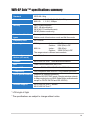
E2564
®
WiFi-AP Solo™ Onboard
3-in-1 Wireless LAN Adapter
54 Mbps
User Guide
E2564
Checklist
First Edition V1
April 2006
Copyright © 2006 ASUSTeK COMPUTER INC. All Rights Reserved.
No part of this manual, including the products and software described in it, may be
reproduced, transmitted, transcribed, stored in a retrieval system, or translated into any
language in any form or by any means, except documentation kept by the purchaser for
backup purposes, without the express written permission of ASUSTeK COMPUTER INC. (“
ASUS”).
Product warranty or service will not be extended if: (1) the product is repaired, modified or
altered, unless such repair, modification of alteration is authorized in writing by ASUS; or (2)
the serial number of the product is defaced or missing.
ASUS PROVIDES THIS MANUAL “AS IS” WITHOUT WARRANTY OF ANY KIND, EITHER
EXPRESS OR IMPLIED, INCLUDING BUT NOT LIMITED TO THE IMPLIED WARRANTIES
OR CONDITIONS OF MERCHANTABILITY OR FITNESS FOR A PARTICULAR PURPOSE.
IN NO EVENT SHALL ASUS, ITS DIRECTORS, OFFICERS, EMPLOYEES OR AGENTS BE
LIABLE FOR ANY INDIRECT, SPECIAL, INCIDENTAL, OR CONSEQUENTIAL DAMAGES
(INCLUDING DAMAGES FOR LOSS OF PROFITS, LOSS OF BUSINESS, LOSS OF USE
OR DATA, INTERRUPTION OF BUSINESS AND THE LIKE), EVEN IF ASUS HAS BEEN
ADVISED OF THE POSSIBILITY OF SUCH DAMAGES ARISING FROM ANY DEFECT OR
ERROR IN THIS MANUAL OR PRODUCT.
SPECIFICATIONS AND INFORMATION CONTAINED IN THIS MANUAL ARE FURNISHED
FOR INFORMATIONAL USE ONLY, AND ARE SUBJECT TO CHANGE AT ANY TIME
WITHOUT NOTICE, AND SHOULD NOT BE CONSTRUED AS A COMMITMENT BY
ASUS. ASUS ASSUMES NO RESPONSIBILITY OR LIABILITY FOR ANY ERRORS OR
INACCURACIES THAT MAY APPEAR IN THIS MANUAL, INCLUDING THE PRODUCTS
AND SOFTWARE DESCRIBED IN IT.
Products and corporate names appearing in this manual may or may not be registered
trademarks or copyrights of their respective companies, and are used only for identification or
explanation and to the ownersʼ benefit, without intent to infringe.
ii
Contents
Features
About this guide .............................................................................. iv
WiFi-AP Solo™ specifications summary.......................................... v
Chapter 1: Product introduction
1.1
1.2
1.3
1.4
Welcome! .............................................................................1-2
Features...............................................................................1-2
LED and antenna port..........................................................1-4
Choosing an appropriate wireless network ..........................1-5
1.4.1 Software Access Point (Soft AP) .............................1-5
1.4.2 Infrastructure mode .................................................1-6
1.4.3 Ad-hoc mode ...........................................................1-6
Chapter 2: Installation
2.1
2.2
Installation............................................................................2-2
2.1.1 System requirements ..............................................2-2
2.1.2 Installing the antenna ..............................................2-2
2.1.3 Signal range ............................................................2-3
Driver and utilities installation ..............................................2-4
Chapter 3: Setting up
3.1
3.2
3.3
3.4
About the setup utilities........................................................3-2
Setting up a wireless access point (Soft AP) .......................3-3
3.2.1 Setting up Soft AP using setup wizard ....................3-3
3.2.2 Setting up Soft AP using setup utility.......................3-5
Setting up a wireless card (Infrastructure) ...........................3-7
3.3.1 Setting up infrastructure using setup wizard ...........3-7
3.3.2 Setting up Infrastructure using setup utility .............3-9
Setting up a wireless card (Ad-hoc) ...................................3-11
3.4.1 Setting up Ad-hoc with setup wizard ..................... 3-11
3.4.2 Setting up Ad-hoc with setup utility .......................3-13
Appendix
Wireless LAN channels ................................................................ A-2
Safety statements ........................................................................ A-4
iii
About this guide
This user guide contains the information you need to install and configure your
ASUS WiFi-AP Solo™ wireless solution.
How this guide is organized
This guide contains the following parts:
•
Chapter 1: Product introduction
This chapter describes the general features of the ASUS WiFi-AP Solo™
wireless solution. The chapter also presents the LED indications, and
recommended WiFi-AP Solo™ network settings.
•
Chapter 2: Installation
This chapter provides step by step instructions on installing the wireless
LAN adapter drivers and software applications using the support CD.
•
Chapter 3: Setting up
This chapter provides information on how to set up the WiFi-AP Solo™ in
your home or office network using the setup wizard.
•
Appendix
The Appendix lists the wireless LAN channels available for use in your
country or location and safety statements.
Conventions used in this guide
To make sure that you perform certain tasks properly, take note of the following
symbols used throughout this guide.
WARNING: Information to prevent injury to yourself when trying to
complete a task.
CAUTION: Information to prevent damage to the components when
trying to complete a task.
IMPORTANT: Information that you MUST follow to complete a task.
NOTE: Tips and additional information to aid in completing a task.
iv
WiFi-AP Solo™ specifications summary
Standard
IEEE 802.11b/g
Data rate
802.11g:
802.11b:
Security
WEP 64-bit encryption
WEP 128-bit encryption
WPA (Wi-Fi Protected Access)
WPA2 (Station mode only)
Network architechture
types
Access point mode
Station mode: Infrastructure mode and Ad-Hoc mode
Frequency band
2.4~2.5GHz
Operating distance
802.11g
Number of connected
devices (AP mode)
up to 64 stations
Antenna
ASUS WiFi-AP SoloTM omni-directional antenna
LED
Green data transmission (AIR) LED
Support OS
Windows®2000, 2003, XP, XP-64bit, 2003-64bit
Compatibility
Fully compatible with IEEE802.11b/g standard products
ASUS special features
Supports 64 stations connection
Supports ASUS EZ WiFi mode: Running wireless network
in sleep mode (only on ASUS Digital Home motherboards
except for P5LD2-VM DH and N4L-VM DH)
Software support
ASUS WiFi-AP Solo™ Wizard
ASUS WiFi-AP Solo™
6, 9, 12, 18, 24, 36, 48, 54Mbps
1, 2, 5.5, 11Mbps
Indoor:
80ft (30m)
Outdoor: 200ft (60m) LOS*
802.11b
Indoor:
130ft (40m)
Outdoor: 1000ft (310m) LOS*
The range varies in different environments
* LOS=Light of Sight
* The specifications are subject to change without notice.
v
vi
Chapter 1
This chapter describes the general
features of the ASUS WiFi-AP SoloTM
wireless solution. The chapter also
presents the LED indications, and
recommended WiFi-AP Solo™ network
settings.
Product introduction
1-1
1.1 Welcome!
Thank you for choosing the ASUS WiFi-AP Solo™ wireless solution!
The WiFi-AP Solo™ is an easy-to-use wireless local area network (WLAN)
adapter designed for home or office use. Conforming to IEEE 802.11g
standard for WLAN, the ASUS WiFi-AP Solo™ is capable of up to 54 Mbps
data transmission rate using the Direct Sequence Spread Spectrum (DSSS)
and the Octogonal Frequency Division Multiplexing technologies. The WiFi-AP
Solo™ is backward compatible with the earlier IEEE 802.11b standard allowing
seamless integration of both wireless LAN standards in a single network.
The WiFi-AP Solo™ also supports several wireless network configuration
including Infrastructure, Ad-hoc, Soft Access Point, and Wireless Bridge
(Wireless Distribution System) giving you flexibility to your existing or future
wireless network configurations.
To provide efficient security to your wireless communication, WiFi-AP Solo™
employs both 64-bit/128-bit Wired Equivalent Privacy (WEP) and Wi-Fi
Protected Access (WPA) encryptions.
With these and many more, ASUS WiFi-AP Solo™ is sure to keep you ahead
in the world of wireless computing.
1.2 Features
No hardware installation
Because the WiFi-AP Solo™ wireless LAN adapter comes embedded in your
ASUS motherboard, no hardware installation is needed. Just install the drivers
and utilities from the motherboard support CD and start computing wirelessly in
no time.
54Mbps speed advantage
With data transmission rate up to five times faster than IEEE 802.11b
standards, the WiFi-AP Solo™ breaks the wireless data transmission speed
barrier to give you faster Internet connection and file sharing capabilities.
Easy integration
The WiFi-AP Solo™ is compatible with all IEEE 802.11b devices so you can
still use your IEEE 802.11b devices in the WiFi-AP Solo™ network.
1-2
Soft access point function
If you are using the 32-bit version of Windows® XP/Server 2003 operating
system, you can transform the WiFi-AP Solo™ into a Software Access Point
(Soft AP). In Soft AP, WiFi-AP Solo™ can support up to 64 stations with
wireless LAN adapters making it an ideal solution for homes and offices with
single Internet connection or network printer.
WiFi-AP Solo™ can perform the AP functions even the computer dozes off;
therefore, the wireless stations that have connected to the WiFi-AP Solo™ can
access Internet, play on-line games, share the network printer so long your
computer is turned on.
Moveable omni-directional antenna
A moveable, omni-directional antenna comes with your WiFi-AP Solo™ to
maximize your wireless coverage.
1-3
1.3 LED and antenna port
The WiFi-AP Solo™ comes with a green data transmission LED (AIR) and an
antenna port located at the motherboard rear panel.
Antenna port AIR LED
The location of the WiFi-AP Solo™ data transmission LED and antenna
port may vary on motherboard models.
LED indicator
Refer to the table below for LED indication.
LED
Status
AIR
On
Off
Blinking quickly
Blinking slowly
1-4
Indication
Power on but no data activity.
Power off or no wireless connection.
Transmitting and/or receiving data.
Site survey.
1.4 Choosing an appropriate wireless network
You can use the ASUS WiFi-AP Solo™ in various wireless network configurations.
It is recommended that you select the most appropriate configuration for your
home or office network before setting up the WiFi-AP Solo™.
The following pictures and descriptions are for reference only and may not
exactly match your actual network configuration.
1.4.1 Software Access Point (Soft AP)
If you wish to share the Internet access with the wireless stations in your
environment, you can configure the WiFi-AP Solo™ as a software access point
(Soft AP). In this mode, the WiFi-AP Solo™ becomes the wireless access point
that provides local area network and Internet access for your wireless stations.
Requirements of using soft AP function:
1. Windows® XP/Windows® Server 2003 operating system;
2. Onboard Ethernet LAN adapter with driver properly installed.
The Soft AP feature is ideal for home/SOHO networks with several computers,
a shared printer and a shared Internet connection.
˝
Internet
ADSL or Cable
Modem (if any)
Printer 1
WiFi-AP Solo™
MODE
Station 4
Station 1
Station 3
Station 2
1-5
1.4.2 Infrastructure mode
An Infrastructure wireless network is
centered on a wireless access point
(AP) that provides Internet access
and LAN commnunication for the
wireless stations. In Infrastruncture
mode, the wireless LAN stations
communicate with each other via
the wireless AP.
In this mode, your WiFi-AP Solo™
functions as a wireless adapter.
It communicates with the LAN
computers and accesses Internet
through the wireless AP.
Internet
˝
ADSL or Cable
Modem (if any) Access Point
Station 1
WiFi-AP Solo™
Station 2
1.4.3 Ad-hoc mode
In the Ad-hoc mode, the WiFi-AP
Solo™ acts as a wireless card and
connects directly to other wireless
device within its operating range. In
the Ad-Hoc mode, your computer
commnunicate with other wireless
stations without an access point
(AP).
WiFi-AP Solo™
Station
Station 1
MODE
Station 2
1-6
Chapter 2
This chapter provides step by step
instructions on installing the WiFiAP Solo™ drivers and utilities to your
computer. This part also provides
information on installing the antenna.
Installation
2-1
2.1 Installation
2.1.1 System requirements
Before installing the WiFi-AP Solo™ drivers and utilities, make sure that your
system meets the following requirements.
•
ASUS motherboard with WiFi-AP Solo™ onboard solution
•
300MHz or higher
•
Minimum 128MB system memory
•
Operating system: Windows® 2000/ XP/ XP-64bit/ Server 2003/
Server 2003 64-bit
•
Optical drive for utilities and driver installation
2.1.2 Installing the antenna
The WiFi-AP Solo™ wireless solution comes with an omni-directional and
moveable antenna to maximize the WiFi-AP Solo™ coverage.
To install the antenna:
1. Locate the wireless LAN antenna
port on the motherboard rear
panel.
2. Connect the antenna twiston connector (female) to the
wireless LAN antenna port
(male).
3. Place the antenna at an elevated location to enhance your wireless LAN
coverage.
Do not place the antenna under your table or in a closed compartment.
2-2
2.1.3 Signal range
The signal range of WiFi-AP Solo™ depends on the operating environment.
Obstacles such as walls and metal barriers could reflect or absorb radio
signals. Devices such as microwave stove can also greatly interfere the
wireless network.
Signal range:
802.11g: Indoor 80ft (30m), outdoor (LOS, Light-Of-Sight) 200ft (60m)
802.11b: Indoor 130ft (40m), outdoor (LOS, Light-Of-Sight) 1000ft (310m)
By default, the device automatically adjusts the data rate and the closer
wireless station is, the better signal and transmit speed it receives. To improve
your wireless transmission, move your wireless stations closer to the WiFi-AP
Solo™.
2-3
2.2 Driver and utilities installation
•
The contents of the motherboard support CD are subject to change
without notice. Visit the ASUS website for driver/utilities updates.
•
If you use a Windows® operating system, your computer auto-detects
the WiFi-AP Solo™ when system boots and displays an Add New
Hardware Wizard window. Click Cancel then proceed with the
following instructions.
To install the WiFi-AP Solo™ driver and utilities:
1. Place the motherboard support CD to the optical drive.
2. The CD automatically displays the Drivers menu if Autorun is enabled in
your computer. Click the wireless driver and follow screen instructions to
install the WiFi-AP Solo™ driver.
3. Select Utilities menu of the support CD and click to install the WiFi-AP
Solo™ utility.
If Autorun is disabled in your computer, locate the Wireless folder under
the root directory of the support CD, then double click the Setup.exe file to
begin installation.
To use soft AP function, you may need to install Ethernet adapter driver.
2-4
Chapter 3
This chapter provides information on
how to set up the WiFi-AP Solo™ in
your home or office network.
Setting up
3-1
3.1 About the setup utilities
After you have installed the WiFi-AP Solo™ drivers and utilities to your system,
you are now ready to setup the WiFi-AP Solo™ in your network.
Make sure that you have selected the most appropriate configuration for
your wireless network before you proceed. Refer to section 1.4 for details.
Make sure you have connected the supplied antenna to the antenna
connector on the motherboard, or the WiFi-AP Solo™ may not be able to
detect other wireless devices in your environment.
The WiFi-AP Solo™ provides two configuration approaches: the setup
wizard and the setup utility. The former scheme provides an easy approach
to the most frequently used functions while the later allows configuring all the
functions, including the advanced settings.
The setup wizard helps you to:
1. configure the WiFi-AP Solo™ as an access point, or wireless station (in
either Infrastructure or Ad-hoc mode);
2. create a network profile (when setting up Ad-hoc).
The setup utility helps you to:
1. configure the WiFi-AP Solo™ as an access point, or wireless station (in
either Infrastructure or Ad-hoc mode);
2. create, edit and delete a network profile;
3. switch to Windows® Zero Configuration Service (Windows XP only) to
configure the wireless station function;
4. enable or disable the WiFi-AP Solo™;
5. show statistics.
To launch the setup utility in the Windows® desktop, double-click
the desktop shortcut.
To switch to the setup wizard, right
click the WiFi-AP Solo tray icon
and select WiFi-AP Solo wizard. To
switch back to the setup utility, select
Config.
3-2
3.2 Setting up a wireless access point (Soft AP)
You can create your own wireless local area network (WLAN) in your home
using the WiFi-AP Solo™ Software Access Point (Soft AP) feature. Create your
own WLAN if:
1. your computer is connected to the Internet;
2. the operating system of your computer is Windows® 2000/ XP/ XP 64-bit/
Server 2003/ Server 2003 64-bit.
3.2.1 Setting up Soft AP using setup wizard
1. Open the WiFi-AP Solo™ setup
wizard by right-clicking the system
tray icon
and selecting WiFiAP Solo Wizard.
2. Select Access Point and
click Next.
3. The system automatically
generates an SSID for the
soft AP. You can rename the
SSID, if desired.
4. Select a Network Security
level for your soft AP. The
configurable options are
Open, Share-WEP, and
WPA-PSK. Select an
appropriate level and click
Next.
3-3
5. If you select Share-WEP or WPAPSK in Step 4, you are required to
input a password. You can choose
to configure the password in
either ASCII or HEX mode. If you
choose HEX mode, input 10 hex
digits for 64-bit encrytion, or 26
hex digits for 128-bit encryption.
Click Next to continue.
6. Select your Internet connection
and click Next.
7. The soft AP configuration is
complete. Record the setup
information on your note and
click Finish to quit the ASUS
WiFi-AP Solo™ wizard.
8. The default IP address of WiFi-AP
Solo™ is 192.168.0.1. To modify the
IP settings, double-click the wireless
network icon in the system tray ->
click Properties -> double-click
Internet Protocol (TCP/IP).
3-4
3.2.2 Setting up Soft AP using setup utility
The setup utility contains six buttons - Status, Config, Survey, Statistics,
Advanced and ICS in the left column. The Survey button is greyed out in soft
AP mode and the ICS button is greyed out in station mode.
1. Open the setup utility and click
Config button. Click the AP/
Station Mode switch button - To
Access Point Mode. The WiFiAP Solo™ is switched to soft AP
mode in several seconds.
2. Click ICS button to configure your
Internet connection which you
wish to share. Select the correct
connection and click Apply
button.
3. Click Config button and enter
the Network Monitor tab.
Click Setup button to enter the
Wireless Network Properties
page of the soft AP.
3-5
4. You are directed to the Wireless
Network Properties page to
setup the soft AP. In this page,
you can change the SSID, select
the commnunication channel
and specify the network security.
When configuration is complete,
click Finish to apply the settings
and return to the setup wizard.
5. The default IP address of WiFi-AP
Solo™ is 192.168.0.1. To modify the
IP settings, double-click the wireless
network icon in the system tray -> click
Properties -> double-click Internet
Protocol (TCP/IP). You can change
the IP address, subnet mask and
default gateway of WiFi-AP Solo™.
6. The soft AP configuration is
finished. You can view in the
Associate Table of the Config
page all the wireless stations that
have connected to the WiFi-AP
Solo™ (Soft AP).
3-6
3.3 Setting up a wireless card (Infrastructure)
In the Infrastructure mode, you can connect to the LAN or Internet, or both,
through a wireless AP.
3.3.1 Setting up infrastructure using setup wizard
1. Open the WiFi-AP Solo™ setup
wizard by right-clicking the system tray
icon
and selecting WiFi-AP Solo
Wizard.
2. Select Station and click Next.
3. Select Infrastructure and click
Next.
4. The wizard searches for available
networks. To search again,
click Refresh button. Select the
wireless network you want to join
and click Next.
3-7
5. Configure the
security settings (if
have) in the Wireless
Network Property
page. Select the key
type, key length and
input the keys. Click
Finish to apply the
settings and return to
the setup wizard.
Ask your network administrator for the wireless AP settings. The WiFi-AP
Solo™ settings must be identical with the wireless AP it connects to.
6. Setting up the TCP/IP for your
computer. If DHCP server function
is enabled on the AP, you can
automatically get the IP address,
subnet mask, gateway and DNS
server from the AP by selecting
Automatically obtain IP address
and Automatically obtain DNS
server. If DHCP server is disabled
or not supported on the AP,
you must manually input these
parameters. When the settings
are complete, click Finish to exit the
setup wizard.
If DHCP server is disabled on the wireless AP in your network, refer to your
network administrator for a valid IP address.
3-8
3.3.2 Setting up Infrastructure using setup utility
You can setup the wireless card connection (Infrastructure) with a wireless AP
and save the settings to a profile.
1. Open the setup utility. Click
Survey button to search for
available wireless networks.
Double-click the AP you want to
join.
2. Configure the
security settings (if
have) in the Wireless
Network Properties
page. Select the key
type, key length and
input the keys. Click
Finish to apply the
settings and return to
the setup utility.
Ask your network administrator for the wireless AP settings. The WiFi-AP
Solo™ settings must be identical with the wireless AP it connects.
3. Setting up the TCP/IP for your
computer. If the DHCP server
function is enabled on the AP,
you can automatically get the IP
address, subnet mask, gateway
and DNS server from the AP by
selecting Obtain an IP address
automatically and Obtain DNS
server address automatically.
If DHCP server is disabled or not
supported on the AP, you must
manually input these parameters.
3-9
If DHCP server is disabled on the wireless AP in your network, refer to your
network administrator for a valid IP address.
4. Click the Status button to view
the information of the WiFi-AP
Solo™. The connection setup is
complete.
5. You can save the settings to a profile for future use. With profiles, it would
be much easier to roam among different sites, for example, a home
network and an office wireless LAN. When roaming from office to home,
double-click the home profile and you are connected to the home network.
Click Config button and enter the
Profile Manager tab. You can see
the wireless AP that you currently
connect to is in the list. In this
page, you can add, remove, edit
the profiles, and appoint a default
profile.
• To add a profile, click Add button
and enter the Wireless Network
Properties page. After you
complete the settings and click Finish, the configurations are saved to a
profile and the profile is listed in the Available Profile window.
3-10
•
To delete a profile, select the profile you want to delete and click Remove.
•
To edit an existing profile, select the profile and click Edit button to enter
the Wireless Network Property page and modify the settings.
•
To duplicate a profile, select the profile from the list and click Duplicate.
•
To set a profile as default, select the profile and click Set Default.
3.4 Setting up a wireless card (Ad-hoc)
If there is no wireless access point in your environment, you can switch your
WiFi-AP Solo™ to the Ad-hoc mode to connect and communicate with other
wireless-enabled computers. Refer to section 1.4.3 for network topology.
3.4.1 Setting up Ad-hoc with setup wizard
1. Open the WiFi-AP Solo™ setup wizard
by right-clicking the system tray icon and
selecting WiFi-AP Solo Wizard.
2. Select Station and click Next.
3. Select Ad-hoc and click Next. If
there is no Ad-hoc node in your
environment, you are directed to
Wireless Network Properties
page to create an Ad-hoc profile
so that you can be detected and
connected by other wireless
stations.
4. Setup the operation
channel and the
wireless network
security settings.
The operation channel
and security settings
must be identical
between two Ad-hoc
nodes. Click Finish to
apply and return to the
wizard.
3-11
5. Select the profile from the list
and click Next.
6. Setting up the TCP/IP for your
computer. In an Ad-hoc network,
you must manually specify IP
address for the WiFi-AP Solo™.
Make sure that the IP address
of the WiFi-AP Solo™ is within
the same subnet as that of the
other ad-hoc node (e.g. If the IP
address of the other Ad-hoc node
is 192.168.0.1, then the IP address
of WiFi-AP Solo™ must be
192.168.0.X, where X = 2 ~ 254).
When the setup is complete, click
Finish to quit the setup wizard.
3-12
3.4.2 Setting up Ad-hoc with setup utility
This section describes how to set up WiFi-AP Solo™ as an Ad-hoc node and let
other wireless station to connect, and how to connect an existing Ad-hoc node.
Setting up WiFi-AP Solo™ as an Ad-hoc node
1. Open the setup utility and
click the Config button. Select
Profile Manager tab. Click Add
button to create a profile.
2. Setup the operation
channel and the
wireless network
security settings.
When configuration is
complete, click Finish
to apply the settings
and return to the utility.
The WiFi-AP Solo™ is
an Ad-hoc node now.
Refer to Appendix-A for the available wireless LAN channels in your country
or region.
3. The default IP address of WiFi-AP
Solo™ is 192.168.0.1. To modify the
IP address for your WiFi-AP Solo™
, double-click the wireless icon in the
system tray -> click Properties ->
double-click Internet Protocol (TCP/
IP).
3-13
4. To connect WiFi-AP Solo™ from
another wireless station, make sure
that the IP address of the station is
within the same subnet as that of
the WiFi-AP Solo™ (e.g. If the IP
address of the WiFi-AP Solo™ is
192.168.0.1, then the IP address
of the station must be 192.168.0.X,
where X = 2 ~ 254). When the setup
is complete, click OK.
5. Click the Status button of the
setup utility to check whether the
connection is established.
Connecting WiFi-AP Solo™ to an existing Ad-hoc node
1. Open the setup utility and click
the Survey button to search for
available Ad-hoc nodes. Doubleclick the Ad-hoc node you wish
to connect.
3-14
4. Setup the operation
channel and the
wireless network
security settings. The
operation channel and
security settings must
be identical with the Adhoc nodes you want to
connect. Click Finish to
apply and return to the
setup utility.
Refer to Appendix-A for the available wireless LAN channels in your country
or region.
4. To connect an Ad-hoc node, you must manually setup the IP address
of WiFi-AP Solo™. Double-click the wireless icon in the system tray ->
click Properties -> double-click Internet Protocol (TCP/IP) to open the IP
configuration page.
Make sure that the IP address of the
WiFi-AP Solo™ is within the same
subnet as that of the station (e.g. If the
IP address of the station is 192.168.0.1,
then the IP address of WiFi-AP Solo
™ must be 192.168.0.X, where X = 2 ~
254). When the setup is complete, click
OK.
5. Click the Status button of the
setup utility to check whether the
connection is established.
3-15
3-16
Appendix
The Appendix-A lists the wireless LAN
channels available for use in your
country or location, and safety warning
statements
A-1
Wireless LAN channels
The IEEE 802.11b/g standard for wireless LAN allocated the 2.4 GHz
frequency band into 13 overlapping operating channels. Each channel
corresponds to a different set of frequencies. The table below shows the center
frequencies of each channel.
Channel
Center
Frequency
Channel
Center
Frequency
1
2.412 GHz
8
2.447 GHz
2
2.417 GHz
9
2.452 GHz
3
2.422 GHz
10
2.457 GHz
4
2.427 GHz
11
2.462 GHz
5
2.432 GHz
12
2.467 GHz
6
2.437 GHz
13
2.472 GHz
7
2.442 GHz
14
2.484 GHz
If several Wi-Fi devices are operating in the same vicinity, the distance
between the center frequencies of channels used must be at least 25MHz
to avoid interference.
The number of channels available for the wireless LAN adapter varies by
country/region. Refer to the table below to determine the number of channels
available in your location.
Country/Region (Regulating Body)
Available Channels
Australia (ACA)
Channels 1 to 13
Belgium (RTT&E/EMC/LVD)
Channels 1 to 13
Bulgaria (RTT&E/EMC/LVD)
Channels 1 to 13
Canada (CSA/cUL 950 3rd Edition)
Channels 1 to 11
China (MII)
Channels 1 to 11
Cyprus (RTT&E/EMC/LVD)
Channels 1 to 13
Czech Republic (RTT&E/EMC/LVD)
Channels 1 to 13
Denmark (RTT&E/EMC/LVD)
Channels 1 to 13
Finland (RTT&E/EMC/LVD)
Channels 1 to 13
France (RTT&E/EMC/LVD)
Channels 1 to 13
Germany (RTT&E/EMC/LVD)
Channels 1 to 13
Greece (RTT&E/EMC/LVD)
Channels 1 to 13
Hong Kong (OFTA)
Channels 1 to 13
(continued next page)
A-2
Country/Region (Regulating Body)
Available Channels
Hungary (RTT&E/EMC/LVD)
Channels 1 to 13
Iceland (RTT&E/EMC/LVD)
Channels 1 to 13
Ireland (RTT&E/EMC/LVD)
Channels 1 to 13
Italy (RTT&E/EMC/LVD)
Channels 1 to 13
Japan (TELEC)
Channels 1 to 13
Luxembourg (RTT&E/EMC/LVD)
Channels 1 to 13
Malaysia (SIRIM/CMC)
Channels 1 to 13
Mexico
Channels 9 to 11
Netherlands Antilles (RTT&E/EMC/LVD)
Channels 1 to 13
Netherlands/Holland (RTT&E/EMC/LVD)
Channels 1 to 13
New Zealand (PTC)
Channels 1 to 13
Norway (RTT&E/EMC/LVD)
Channels 1 to 13
Portugal (RTT&E/EMC/LVD)
Channels 1 to 13
Saudi Arabia
Channels 1 to 13
Singapore
Channels 1 to 13
South Korea (KS)
Channels 1 to 13
Spain (RTT&E/EMC/LVD)
Channels 1 to 13
Sweden (RTT&E/EMC/LVD)
Channels 1 to 13
Switzerland (RTT&E/EMC/LVD)
Channels 1 to 13
Taiwan (DGT)
Channels 1 to 11
Turkey (TTAS)
Channels 1 to 13
United Kingdom (RTT&E/EMC/LVD)
Channels 1 to 13
United States (FCC)
Channels 1 to 11
Channels 1, 6 and 11 are independent and do not overlap each other. We
recommended that you tune your wireless LAN adapter to these channels.
A-3
Safety statements
Federal Communications Commission Statement
This device complies with FCC Rules Part 15. Operation is subject to the
following two conditions:
•
This device may not cause harmful interference, and
•
This device must accept any interference received, including interference
that may cause undesired operation.
This equipment has been tested and found to comply with the limits for a
class B digital device, pursuant to Part 15 of the Federal Communications
Commission (FCC) rules. These limits are designed to provide reasonable
protection against harmful interference in a residential installation. This
equipment generates, uses, and can radiate radio frequency energy
and, if not installed and used in accordance with the instructions, may
cause harmful interference to radio communications. However, there is
no guarantee that interference will not occur in a particular installation.
If this equipment does cause harmful interference to radio or television
reception, which can be determined by turning the equipment off and on,
the user is encouraged to try to correct the interference by one or more of
the following measures:
•
Reorient or relocate the receiving antenna.
•
Increase the separation between the equipment and receiver.
•
Connect the equipment into an outlet on a circuit different from that to
which the receiver is connected.
•
Consult the dealer or an experienced radio/TV technician for help.
CAUTION! You are cautioned that changes or modifications not expressly
approved by the party responsible for compliance could void your authority
to operate the equipment.
Reprinted from the Code of Federal Regulations #47, part 15.193, 1993.
Washington DC: Office of the Federal Register, National Archives and Records
Administration, U.S. Government Printing Office.
A-4
Regulatory Information/Disclaimers
Installation and use of this Wireless LAN device must be in strict
accordance with the instructions included in the user documentation
provided with the product. Any changes or modifications (including the
antennas) made to this device that are not expressly approved by the
manufacturer may void the userʼs authority to operate the equipment. The
manufacturer is not responsible for any radio or television interference
caused by unauthorized modification of this device, or the substitution of
the connecting cables and equipment other than manufacturer specified. It
is the responsibility of the user to correct any interference caused by such
unauthorized modification, substitution or attachment. Manufacturer and its
authorized resellers or distributors will assume no liability for any damage
or violation of government regulations arising from failing to comply with
these guidelines.
CAUTION! To maintain compliance with FCCʼs RF exposure guidelines,
this equipment should be installed and operated with minimum distance
[20cm] between the radiator and your body. Use on the supplied antenna.
Unauthorized antenna, modification, or attachments could damage the
transmitter and may violate FCC regulations.
Safety Information
In order to maintain compliance with the FCC RF exposure guidelines,
this equipment should be installed and operated with minimum distance
[20cm] between the radiator and your body. Use only with supplied
antenna.
Unauthorized antenna, modification, or attachments could damage the
transmitter and may violate FCC regulations.
CAUTION! Any changes or modifications not expressly approved in this
manual could void your authorization to use this device.
MPE Statement
Your device contains a low power transmitter. When device is transmitted it
sends out Radio Frequency (RF) signal.
A-5
Caution Statement of the FCC Radio Frequency
Exposure
This Wireless LAN radio device has been evaluated under FCC Bulletin
OET 65C and found compliant to the requirements as set forth in CFR 47
Sections 2.1091 and 15.247(b)(5) addressing RF Exposure from radio
frequency devices. The radiation output power of this Wireless LAN device
is far below the FCC radio frequency exposure limits. Nevertheless, this
device shall be used in such a manner that the potential for human contact
during normal operation – as a mobile or portable device but use in a bodyworn way is strictly prohibit. When using this device, a certain separation
distance between antenna and nearby persons has to be kept to ensure
RF exposure compliance. In order to comply with the RF exposure limits
established in the ANSI C95.1 standards, the distance between the
antennas and the user should not be less than [20cm].
RF Exposure
The antenna(s) used for this transmitter must not be co-located or
operating in conjunction with any other antenna or transmitter.
A-6