1
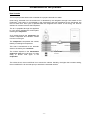
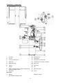
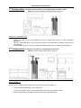
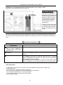
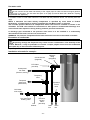
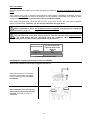
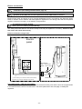
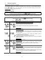
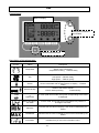
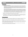
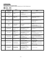
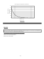
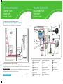
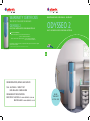
WARRANTY CERTIFICATE MAINTENANCE AND USER MANUAL - WARRANTY TO BE KEPT BY THE USER OF THE APPLIANCE ODYSSEO 2 ODYSSEO 2 HEAT PUMP WATER HEATER USING NON-HEATED AIR HEAT PUMP WATER HEATER USING NON-HEATED AIR Duration of the warranty* - Water heater (cylinder): 5 years in domestic installations 3 years in commercial installation - Electric elements and components parts: 2 years in domestic installations 1 year in commercial installations The warranty covering service items, or replacement unit, expires at the end of the original purchase warranty period. * see details about warranty conditions and exclusions inside the user manual EN FOR INFORMATION, REPAIRS AND SERVICE CALL: AUSTRALIA : 1800 677 857 NEW ZEALAND : 0800 422 000 FOR WARRANTY REGISTRATION: REGISTER AT: AUSTRALIA - www.atlantics.com.au NEW ZEALAND - www.atlantics.co.nz GUIDE TO BE KEPT BY THE USER WIRING DIAGRAM WIRING DIAGRAM STARTING YOUR HEAT PUMP WATER HEATER MAINTAINING YOUR HEAT PUMP WATER HEATER In order to protect the tank against corrosion, the water heater must remain switched on at all times. The wires in the electric cable are crimped. If you need to cut them, remember to crimp them again before connecting to the electric power supply. Electric panel Active – brown Neutral –blue FOR TIME CLOCK CONTROL - TIME OF USE TARIFF: 240 volt supply with 2 amp protection connected to the black auxiliary wire and the time clock programmed in accordance with the time of use tariff hours. Set HCHP parameter to ON, see page 15 setting the regulation. FOR ACI PROTECTION: The HPWH must remain connected to the permanent power supply at all times so that the operation of the (ACI) anti-corrosion protection of the water heater is ensured. For more information Please refer to the «Electric connections» and «Getting started» chapters in this manual. 1 Permanent power supply 8 1,800W steatite backup 15 Fan 2 Off-peak hours cable 9 Pocket 16 Fan condenser 3 Regulation 10 Mechanical safety device 17 Safety pressure switch 4 Incoming air sensor 11 Hot gas solenoid 18 Safety horn 5 Evaporator sensor 12 Compressor condenser 19 Heat pump shells 6 Pocket sensor 13 Compressor 7 Anti-corrosion protection 14 Low-speed condenser Contents Important recommendations....................................................................................................... 2 Transportation & Storage ...................................................................................................................... 2 Safety instructions ................................................................................................................................. 2 Presentation of the product ........................................................................................................ 3 How it works ........................................................................................................................................... 3 Technical characteristics ...................................................................................................................... 4 Dimensions / components .................................................................................................................... 5 Installation .................................................................................................................................... 6 Selecting the location ............................................................................................................................ 6 Installing the product............................................................................................................................. 9 Hydraulic connection............................................................................................................................. 9 Air connections. ................................................................................................................................... 11 Electric connections ............................................................................................................................ 12 Getting started...................................................................................................................................... 14 Use............................................................................................................................................... 16 Control panel ........................................................................................................................................ 16 Description of the pictograms: ........................................................................................................... 16 Description of the modes .................................................................................................................... 17 Adapting the mode of your appliance to your needs ....................................................................... 19 Recommendations – Maintenance & Repairs ......................................................................... 20 Document reference : 112 30 618 C Controlled : Mars 2012 Advice for users ................................................................................................................................... 20 Domestic maintenance ........................................................................................................................ 20 Maintenance by a qualified professional ........................................................................................... 21 Troubleshooting . ................................................................................................................................. 22 Fault diagnosis for professionals....................................................................................................... 23 After-sales............................................................................................................................................. 25 Warranty Conditions ............................................................................................................................ 26 Warranty Exclusions............................................................................................................................ 26 Good, compliant installation Guidelines : Atlantics Europe : ......................................................... 27 -1- Important recommendations Transportation & Storage The product can be inclined at 90° on one side. This side is clearly shown by a sign on the packaging. It is forbidden to incline the product on the other sides. An indicator shows whether the product has been transported and handled according to our recommendations. You are advised to make sure that these recommendations are followed. If the inclination indicator is red, our warranty is null and void. We cannot be held liable for any faults in the product resulting from transporting or handling the product in a manner that does not comply with our recommendations. It is strictly forbidden to stack this product. Acceptable positions Forbidden positions Safety instructions Installing and starting up heat pump water heaters may be hazardous due to high pressure and live parts. The heat pump water heater must be installed, started up and maintained by trained and qualified personnel only. This device is not intended for use by persons (including children) with physical, sensory or mental disability, or by persons lacking experience or knowledge, unless they have received from a person in charge of their safety adequate supervision or preliminary instructions on how to use the device. Care must be taken at all times to keep children from playing with the device. -2- Presentation of the product How it works The heat pump water heater uses unheated air to prepare domestic hot water. Heat energy extracted from the ambient air is absorbed by the refrigerant through heat transfer at the Evaporator. This energy is concentrated by the Compressor and then transferred by the Condenser into the hot water tank. This cycle is repeated after the refrigerant has cooled. A low energy fan ensures ambient air movement across the Evaporator. AIR The air is propelled through the appliance by a fan, which ventilates the various parts, including the evaporator. As it passes through the evaporator, the coolant evaporates and absorbs calories from the incoming air. Tank The compressor compresses the coolant, thereby increasing its temperature. Compressor Evaporator This heat is transferred to the domestic water in the tank by the condenser. The coolant expands in the thermostatic expansion valve and cools down. It is then ready to absorb heat again in the evaporator. Condenser Expansion valve The colder the air, the more difficult it is to extract the calories. Similarly, the higher the hot water setting, the more difficult it is for the heat pump to transfer the extracted calories. -3- Technical characteristics Dimensions mm H 1897 x l 591 x D 674 Empty weight kg 90 Capacity of the tank L 270 Hot water / cold water connection 3/4 ’ ’ M Corrosion-proof protection Impressed current anode Minimum conductivity of the water μS/cm 40 Rated pressure Permissive excessive operating pressure kPa Mpa Electric connection (voltage / frequency) 560 1 240 V single phase 50 Hz Maximum total power input of the appliance W 2635 Average power input of the heat pump W 425 Maximum power input of the heat pump W 755 Power output of the heat pump (under nominal conditions +15°C) W 1660 Power input of the electric backup W 1880 Water temperature setting range of the heat pump °C Operating temperature range of the heat pump (air temperature) °C 45 to 62 (factory setting = 55°C) -5 to 35 Vacuum air flow (without duct) (230V) Speed 1 m3/h 230 3 m /h 390 Pa 25 Speed 2 Admissible head loss in the air circuit without impacting performance Noise level** dB(A) 54 Acoustic pressure at 2m in the open dB(A) 37 Coolant fluid Nota : R134a GWP (Global Warming Potential) is 1350 -/kg R134a / 1.35 Certified performances at an air temperature of 7°C (CDC LCIE 103-15A) and 25Pa** ducting Coefficient of performance (COP) (230V) 3,1 QPr (over 24h) (230V) kWh Heating time* (230V) 0,77 8h19min Performance measured at an air temperature of 15°C (CDC LCIE 103-15A) without ducts** Coefficient of performance (COP) (230V) 3,8 QPr (over 24h) (230V) kWh Heating time* (230V) 0,74 7h30min Other performances Max. quantity of water mixed at 40°C (setting at 62°C) L 455L * Tested in a reverberation chamber in accordance with the measurement standard NF EN ISO 3741, water heaters without accessories, average measurement when heating from a water temperature of 21 to 57°C at an ambient air temperature of 20°C. ** Performances measured when heating water from 15°C to 51°C according to the protocol in the specifications of the NF Electricity performance brand N° LCIE 103-15A for standalone accumulator tank thermodynamic water heaters (based on the standard EN 255-3). This appliance complies with Directives 2004/108/EEC on electromagnetic compatibility and 2006/95/EEC on low voltage. -4- Dimensions / components 1 Air outlet 10 Hot water inlet 2 Air inlet 11 Compressor 3 Fixed unit attachment 12 Evacuation of condensate 4 Fixed feet 13 Compressor permanent condenser 5 Cold water inlet 14 Evaporator 6 Pocket 15 Fan wiring 7 Sheath 16 Fan 8 Electric heating element (ceramic element) and mechanical safety device Regulation 17 Expansion valve 18 Cover 9 Not shown: - Manual - Condensate evacuation tube - -5- Dielectric coupling Installation Selecting the location in compliance with IEC 60 529 Standard, AS60529:2004 Capable of withstanding a weight of at least 400 kg (the area under the water heater) The place where the appliance is installed must comply with protection index IP X1B according IEC 60 529 Standard and AS60529:2004 standard and in compliance with electrical wiring rules of Aus/Nz Configuration without ducts Configuration with ducts semi-ducted Type of room Unheated room at a temperature Room at least above freezing above 5° and isolated from the Recommended room = habitable heated rooms in the dwelling space (the heat released by the water Recommended room = underground heater is not lost), near the exterior or semi-underground, a room where walls the temperature is higher than 10°C Do not install near bedrooms to avoid all year long, well vented location disturbance by the noise Examples of rooms Garage, boiler room, basement, Laundry, cupboard in the hallway, etc. laundry room, etc. Volume of the room from > 20m3 > 20m3 which the air is taken Resistance of the floor Temperature of the room where the water heater is installed Temperature of the incoming air Height Required surface area 5°C to 35°C, when the water heater is not working 1°C to 35°C 3°C to 35°C -5°C to 35°C > 2m10 > 2m20 with bent outlet (height of an insulated bend = approx. 300mm) 800 x 800 (l x D). See diagram below The surface must be level (591+400) x 700 (l x D). See diagram below The surface must be level Configuration without ducts 200 mm Configuration without ducts Configuration without ducts Configuration with ducts CAUTION : failure to follow the recommendations for installation may result in poor system performance. -6- Recommended configurations 1st Configuration: installation without ducts in an unheated space (Volume > 20m3) FAN set to 0 (see Setting the regulation section, page 15). Examples of unheated rooms: - Garage: recovery of free heat released by the car engine after use or by other household appliances. Laundry : dehumidification of the room and recovery of heat released by washing machines and tumble driers. Semi-underground room: recovery of free heat released by the floor and walls of the basement. 2nd Configuration: installation in a heated or unheated room with ducts FAN set to 2 (see Getting start section, page 14). Recommendations: Comply with the maximum duct lengths (see Air connections section, page 11). - Use thermally insulated rigid or semi rigid ducts - Provide air flow grills at the duct inlet and outlet to prevent entry of foreign bodies - Ensure that grills do not impede necessary air flow by being obstructed -7- Configuration tolerated under certain conditions Installation in an unheated space with one duct (outlet or inlet, volume > 20m3) FAN set to 1 (see Getting start section, page 14). Possible consequences: - The negative pressure in the room due to the expulsion of the exterior air may result in air entering through the doors and windows. Provide an air inlet (same diameter as the ducts) from the exterior in order to avoid sucking air from the heated space. - Caution: in winter, the air will be colder than the air expelled by the water heater, resulting in a drop in temperature in the garage. * In warmer climates ducts may be reversed to provide cold air into an adjacent room for cooling. Connect (air in) from outside and (air out) into the adjacent room. NOTE: It is not recommended to reverse ducts (air out) into the room that the HPWH is installed. This will reduce the COP and increase the cooling of the room. Unsuitable configurations Prohibited Ducting installation configurations The water heater draws in air from a room containing a charged source of heat used to heat the room. Connection to mechanical ventilation Connection to the roof space Related risks Uses heat energy from a higher cost source. The greasy vapour and dust that may flow through the ducts of the mechanical ventilation system can reduce the life time of your water heater. If the insulation between the ceiling and the roof space is insufficient, this installation may result in heat loss from the house. In extreme cases, condensation may appear on the ceiling of the rooms beneath the cooled parts of the roof space. Risk of falling objects and aspiration of dust by the raised water heater in this configuration, that can reduce the life time of your water heater. Other prohibitions: - There must be no Heat Pump Air Access connection between the device and a tumble dryer. - Avoid dusty rooms - Do not draw in air containing solvents or explosives - Do not connect the appliance to hoods evacuating fatty or polluted air - Do not install the water heater in a room that freezes - Do not place anything on the top of the water heater - Do not install in an attic -8- Installing the product 1- Transport the water heater to the place where it is to be installed. 2- Cut the cardboard skirting along the dotted lines. 3- Take the water heater off the pallet and place it by the hydraulic connection. +/- 1° MAXIMUM! The water heater must be installed on a smooth and horizontal floor. If this is not the case, it must be levelled using the supporting feet. If this precaution is not taken, problems may occur evacuating the condensates, resulting in frosting. In accordance with AS/NZS 60335.2.21 the water heaters must be fixed to the ground using the attachment provided and in compliance with the New Zealand Building Code Clause G12, Seismic restraint of storage water heaters. The clearance required needs to be adequate for service/replacement of cold water inlet piping devices, PTR valve and tempering valves (where fitted), elements and thermostats. This may be facilitated by correct orientation of the cover positions when installing. There are no operational clearance limitations to surrounding structure. PTR valve removal requires approximately 150 mm for withdrawal. AS/NZS 3500.4 – National plumbing & drainage. Hot Water Supply Systems – Acceptable solutions. Combustible Material : It is recommended to not place combustible material on or adjacent to the water heater. Internal Installation Safe Tray : For internal (inside home) installations, a safe tray is recommended in accordance with AS/NZS 3500.4. Hydraulic connection Cold water inlet Before making the hydraulic connection, it is essential to clean the feed pipes thoroughly to avoid the risk of metal or other particles entering the tank or the water heater. Cold water piping should be provided with a 500 – 560 kPa Pressure Limiting Valve at the point of cold water connection to the water heater. In addition to the Pressure Limiting Valve, it is a requirement of AS 3500.4 & NZBC G12 that both a Stop Valve and a Non Return Valve are installed upstream of the Product. No parts (stop valve, pressure reducer, etc.) must be placed between the pressure limiting valve and the cold water inlet of the water heater, apart from a copper pipe. Note: since limited water discharge from pressure limiting valve is normal in the heating operation, the discharge pipe needs be connected to external drain. -9- Hot water outlet Do not connect the hot water inlet directly to the copper pipes in order to avoid iron/copper galvanic couples (risk of corrosion). The hot water inlet (item 10 on page 5) must be fitted with a dielectric coupling (supplied with the appliance). If corrosion occurs on a hot water inlet that is not fitted with this protective device, our warranty does not apply. Where a maximum hot water delivery temperature is specified by Local, State or Federal Regulations, a Tempering Valve shall be installed at the Hot Water Outlet, as required. The included specified Pressure & Temperature Relief Valve must be installed as shown in the schematic. The PTR valve should be connected to a drain point to accommodate discharge as a result of both water expansion during heating, and also pressure fluctuations. A discharge pipe connected to the pressure relief valve is to be installed in a continuously downward direction and in a frost- free environment. WARNING: The Pressure Temperature Relief valve and drain line must not be sealed or blocked. Evacuation of condensate Air passing through the Evaporator may result in some condensation. If the humidity of the location Warrants, it may be preferable to connect a simple polymer hose from the Condensate Drain (Item 16), to the convenient PTR drain point. Depending on the humidity of the air, up to 0.25l/h of condensate may form. Installation schematic for example : Connection tee (Supplied) Dielectric fitting (Supplied) PTR Valve (700 kPa) Untempered hot water (Kitchen, laundry) Tempering valve Tempered water 50°C (Bathrooms) Expansion control valve Cold water main supply Non-return and isolating valve Line Strainer Pressure Limiting Valve (560 kPa) Drain line - 10 - Drain line Air connections. Your heat pump water heater can be fitted with ducting accessories that are not supplied with the water heater. If the volume of the room in which the thermodynamic water heater is installed is insufficient, it can be connected to 160 diameter air ducts. If the air ducts are not insulated, condensation may appear on them during operation. Therefore, it is essential to choose insulated air ducts. Poor ducting (crushed ducts, ducts that are too short or too many corners, etc.) may have a negative impact on performance. Therefore, you are strongly advised to use rigid ducts. When connected to ducts, the regulation must be adjusted accordingly (see Setting the regulation section, page 15). The total head loss in the ducts and accessories of the air inlet and outlet must not exceed 150 Pa. The head losses must be calculated using the measuring tools supplied by the manufacturer and on the basis of the proposed ducting accessories. Total duct length* with the wall-mounted air Number of bends inlet and outlet in the catalogue 0 bends 8m 1 x 90° bend 7m 2 x 90° bends 5m (*) semi-rigid aluminium duct Installing the coupling accessory for duct ref. 900366 Refer to the installation instructions supplied with the kit. If the ceiling is too low to screw the accessory from the top, remove the cover by undoing the 6 clips with a screwdriver Then return the cover and clip into place once the accessory has been installed. The ducts can now be connected. - 11 - Electric connections Caution: the water heater must be filled with water first, before making the electric connections (see Getting started section, page 14). The HPWH must remain connected to the main power supply at all times so that the operation of the (ACI) anti-corrosion protection of the water heater is ensured. Electrical work must be carried out by a licensed tradesperson and in accordance with Electrical Wiring Rules of Aus/NZ. Circuit Isolation and fixed appliance regulations of the Wiring rules shall be complied in regard to connection to supply, circuit isolation, and protection. The appliance must be earthed. Never power the heating element directly. The safety thermostat fitted to the electric backup must only be repaired in our factory. Failure to obey this clause will cancel the warranty. Electric connection using a timer Electric panel Timer (*) 16A 2A 2x0.75 mm² Active – red or brown Neutral – white or blue M 3x1.5 mm² (*) This assembly is not universal. Refer to the assembly instructions of your timer, depending on the model. FOR TIME CLOCK – TIME OF USE TARIFF: 240 volt supply with 2 amp protection connected to the black auxiliary wire and the time clock programmed in accordance with the time of use tariff hours. Set HCHP parameter to ON, see page 15 setting the regulation. - 12 - Electric connections FOR RIPPLE CONTROL: NEW ZEALAND ONLY 240 volt supply with 2 amp protection connected to the black auxiliary wire. Set HCHP parameter to ON, see page 15 setting the regulation. The diagram shown is only the functional configuration. Wiring details (ie. switching, fusing, method of isolation, neutrals and their locations must comply with statutory regulations and codes of practice.) FOR CONTROLLED TARIFF: NEW ZEALAND ONLY - 13 - Getting started 1. 2. Filling the water heater. Fill the water heater by opening all hot water taps and opening the cold water inlet to allow the water heater to fill and air in the system to be expelled. Close each hot water tap, as the flow becomes free of air. Check all piping for leaks. Check that water flows freely by gently operating the lever on the Pressure Temperature Relief valve. Power should not be turned on until the water heater is completely filled with water. Checking good working order Switch on the water heater. Check the screen for errors. If an error appears, refer to the system diagnostic section. The temperature setting appears. After 3 minutes the compressor and the fan start. Select the "FAN" setting and configure according to the recommendations in Setting the regulation. After the compressor has been working for about 10 minutes, the temperature at the air outlet is at least 3 to 4°C below that of the incoming air. The water drips out of the drain of the pressure limiting valve. This drain must be connected as described in Hydraulic connection, page 9. This is completely normal, the water is expanding due to the heat. Check that the connections are watertight again. If the check is OK, your appliance is ready. It is now working according to the factory settings, in AUTO mode. Refer to the settings section in this manual to optimise the operation of your appliance. NOTE When heating up with the electric backup and depending on the quality of water, the water heater may make a slight kettle-like noise. This noise is normal and is not a sign of a faulty appliance. The relief of partial vacuum. A vacuum would be relieved from the system whenever a tap is opened as the outlet is at atmospheric pressure and the tank is at mains pressure. - 14 - 3. Setting the regulation Adjusting the temperature set point The temperature setting of your appliance is adjusted to 55°C in the factory. It can be adjusted simply by & directly on the default display. The lower the temperature setting of the heat pump, pressing the better the coefficient of performance (COP). Possible values: 45 to 62 Settings to be adjusted To open or close the setting menu, press + at the same time. In this menu, all the adjustable settings can be checked and changed, if necessary. The default values in the factory settings guarantee optimal operation. Once the menu is open, press then press & to choose a setting, to change the value of the settings. Time clock control function for time of use tariff If the HPWH is controlled by a time clock or with a ripple relay connected to the 2x0.75 cable then move the parameter to ON. If 2x0.75 cable is not connected, then the parameter must be OFF. Default value: OFF Connecting to ducts 0 corresponds to water heaters without ducts. The regulation then adjusts the noise level of the fan. In this configuration, the heat pump stops working if the room freezes. 1 corresponds to semi-ducting, with a single duct installed, usually to evacuate the cold air out of the room. 2 corresponds to ducts on both the inlet and the outlet. In these two positions, the regulation adjusts the fan so that it can withstand additional head losses. Default value: 0 Possible values: 0, 1 or 2 Avoid Legionella This parameter is used to activate the legionnaires disease protection mode: Once every 7 days, all domestic hot water is heated to 60C. Default value: OFF Electric only mode This setting is used in the event of heat pump failure in AUTO, BOOST and ABSENCE modes in order to guarantee a minimum hot water supply before the technician intervenes. Note: In this mode as only the element is heating the unit, approximately one half of the volume of hot water is immediately available. Default value: OFF The value of a setting is validated by proceeding to the next setting. - 15 - Use Control panel Back-lit display Navigation buttons in the modes Mode selection button Description of the pictograms: Symbol Name Description Compressor Status of the compressor: Compressor working Flashes slowly Fan Status of the fan: Low speed → Flashes slowly High speed → Flashes quickly Sensor Indication of the physical position of the sensors Sensor associated with the temperature on display → Flashes slowly Electric backup Status of the electric resistor: Electric backup working Flashes slowly Time of use hours or Peak hours In TOU / peak hours mode, the symbol corresponding to the mode is displayed. Risk of shortage of hot water In ECO mode, shows that the air temperature may result in a shortage of hot water. Minimum Indicates that the value on display is the minimum detected by the sensor. MAXIMUM! Indicates that the value on display is the maximum detected by the sensor. Information Indicates that you are in the information menu. - 16 - Incoming air temperature Air temperature sensor in the flow of ambient air Evaporator temperature Temperature sensor on a cross in the evaporator Water temperature Water temperature sensor in the pocket Heat pump time Shows the working time of the water heater heat pump in hours Elec time Shows the working time of the water heater electric backup in hours Description of the modes Graphical icons Description Optimised management of the heat pump and the electrics for guaranteed comfort Heat pump only working Forced operation with electrics + heat pump when heating Long absence: water heating set to anti-freezing mode and restart on the last day of absence Indicator This mode is selected when the cursor is positioned above the icon. Indication of the various sensor temperatures and the operating time of the heat pump or the electric backup AUTO mode This mode automatically selects the energy source for maximum savings, while guaranteeing that the water is sufficiently hot. The water heater always selects the heat pump first. If the air temperatures are not in the operating range, or if a fault is detected in the heat pump, the electric backup is automatically selected to guarantee a sufficient volume of hot water. Examples: Severe winters Use of 3/4 of the available volume of hot water Air temperature about 1°C Selection by the regulation: Heat pump plus electric backup Winter Use of 3/4 of the available volume of hot water Air temperature about 7°C Selection by the regulation: Heat pump only, with authorisation to continue even in case time clock signal is off (“HP” on the screen) - 17 - Summer Use of 2/3 of the available volume of hot water Air temperature about 18°C Selection by the regulation: Heat pump only and only when time clock signal is on (“HC” on the screen) ECO mode This mode uses the heat pump only to produce hot water. Under certain conditions, this mode may result in shortages of hot water (mainly due to air temperatures outside the operating range). BOOST mode BOOST mode can be used to force the heat pump and the electric backup to work at the same time in the event of high demand. The regulation automatically returns to the previous mode at the end of the cycle. ABSENCE mode This mode helps to protect the tank when the user is absent. The tank is protected against corrosion and the regulation heats the water to above 7°C. Use the arrows to select the number of days during which you will be absent. The length of the absence can be set to between 1 and 99 days. If a number of days is not selected, the water heater remains in ABSENCE mode permanently. On the last day of the period of absence, the water heater performs a cycle to avoid Legionella. The regulation automatically returns to the previous mode at the end of the ABSENCE mode. INFO mode In this mode, it is possible to view the temperatures measured by the various sensors, the maximum and minimum values measured and the time for which the heat pump or the electric backup has been working. Values can be reset by pressing + at the same time. Automatic defrost The water heater is fitted with a defrost function. In negative temperatures, the water heater is automatically defrosted by opening a solenoid, which sends the hot gas from the compressor directly to the evaporator, where the frost melts. In positive temperatures, only the fan is used to defrost the heat exchanger. The defrost mode is activated by the temperature sensor in the evaporator. This temperature sensor can detect the formation of frost, irrespective of the air temperature or the configuration of the system. The defrost cycle lasts a maximum of 15 minutes. Fan controls When FAN is set to 0 (FAN 0), the water heater draws the air in from the room. The fan permanently works at low speed in order to reduce the noise level, while producing a sufficient volume of hot water. Do not use ducts and the FAN 0 setting at the same time. The FAN 1 setting is used when a single duct is installed, usually on the air outlet. This configuration evacuates the cold and dry air from the room. The FAN 2 setting is used when exterior ducts are installed on the air inlet and outlet. In the positions FAN 1 or FAN2, the fan operates at high speed to compensate for the head loss caused by the ducts. In the positions FAN 0 or FAN 1, the lower limit for operation with the heat pump is an air temperature of 3°C, in order to prevent the water heater from freezing (-5°C in FAN 2). - 18 - Adapting the mode of your appliance to your needs 1. Calculate your daily needs in terms of a number of showers (1 bath = 3 showers) Example: daily need = 3 showers + 1 bath => 6 showers 2. Identify the mode that best meets your needs in the table below Number of showers per day EXTRA COMFORT COMFORT 4 2 5 3 6 4 7 5 8 6 9 7 AUTO ECO * Setting OP/P Permanent X X X OP/P Permanent X X X X X X X X 51 55 62 51 55 62 * Switching to AUTO mode is recommended if the temperature of the inlet air may drop below the lower operating limit at night (see Selecting the location, page 6). AUTO mode guarantees a given volume of hot water by using the electric backup under severe weather conditions. Comments: If your selection does not produce the quantity of hot water that you need, switch to the mode in the next higher level. If your needs vary, occasionally or for a lengthy period, adapt the mode to your requirements. 3. Set the appliance to the mode you have identified (see Setting the regulation, page 15) - 19 - Recommendations – Maintenance & Repairs Advice for users Flushing of sediment and draining : To flush or to drain the water heater, power must be turned off and then turn off the cold water supply to the water heater. The lever on the pressure and temperature relief valve should be opened but care should be taken so the lever does not snap back as it could damage the valve seat. The pressure in the water heater will be released when the lever is opened. The union at the cold water inlet to the water heater should be undone and a hose should be attached to the water heater side of the union. The other end of the hose should go to a drain. Opening the pressure and temperature relief valve allows air into the water heater and for the water to drain. Following complete draining of the water heater, the closest hot water taps may be opened fully and the pressure and temperature relief valve closed with care. Following reconnection at the cold water inlet, the cold water stop valve is now opened fully and the water heater may be filled with cold water and flushed through to ensure the cylinder contains no sediment and is clean. Finally the closest hot taps are closed and power may be turned on again to the completely filled water heater. In the event of an anomaly - the heater does not heat or steam is released from the Pressure Temperature Relief valve - switch off the electric power supply and contact your reseller. This appliance is not intended for use by persons (including children) with reduced physical, sensory or mental capabilities, or lack of experience and knowledge, unless they have been given supervision or instruction concerning use of the appliance by a person responsible for their safety. Domestic maintenance Water heaters do not require much domestic maintenance by the user. Operate the Pressure Temperature Relief valve once or twice a month to eliminate any residue of scaling and check that it is not blocked. Regularly check the display for alarms. If an alarm appears, refer to the Troubleshooting section, page 22). DANGER: Failure to operate the Pressure Temperature Relief valve easing gear at least once every six months may mask a problem with the water heater. Continuous leakage of water from the Pressure Temperature Relief valve may indicate a problem with the water heater. It is not unusual for the Pressure Temperature Relief valve to allow a small quantity of water to escape during the heating cycle and this must be left open to the atmosphere. - 20 - Maintenance by a qualified professional To protect the performance of your appliance for many years to come, it must be checked by a professional every 2 years. Switch off the electric power supply (circuit breaker, fuses, etc.). Drain the tank: close the cold water inlet (isolating valve), open a hot water tap, set the safety valve to the drain position. Remove the front cover. Disconnect the wires from the terminals of the thermostat. Remove the heating assembly. Remove any scaling that is deposited in the shape of sludge or a film on the floor of the tank and thoroughly clean the ducts of the heating elements and the thermostat. Do not scratch or strike the scaling on the walls, or you might damage the coating. Any residue can be removed using a water and dust vacuum cleaner. Clean the interior of the sheath to remove any scaling. The anti-corrosion anode is made of titanium and does not need to be inspected or replaced. Install the heating assembly with a new seal. Tighten the nuts gradually to a reasonable torque. Alternately tighten nuts that are opposite one another. Fill the water heater, with a hot water tap open. When the water reaches the hot water tap, the tank is full. Check the seal for leaks and then install the thermostat and its support and connect the electric power supply. On the following day, check the seal again for leaks and slightly tighten the bolts, if necessary. Check the electric connections. Check that the temperature sensor is properly positioned in the pocket near the electric backup. The sensor must be fully inserted in the pocket. Evaporator: Check that the evaporator and the fan are clean once a year. If these parts are soiled, the performance of the heat pump will be diminished. To access the evaporator, remove the cover by unclipping it with a screwdriver. The left half-shell can also be removed in cases of difficult access. If necessary, clean the evaporator and the fan with a soft brush. Brush the evaporator very carefully to avoid damaging the vanes. If the vanes are folded, straighten them using a suitable comb. Always switch off the appliance before opening the front cover or the top cover Expansion valve: Only personnel specialised in refrigerating systems can access the adjusting screw of the expansion valve. Adjusting the expansion valve without the manufacturer's approval may result in the product warranty being cancelled. In general, you are advised not to touch the settings of the expansion valve without having first tried all the other repair solutions. Condensate evacuation tube Check that the condensate evacuation tube (item 12 on page 5) is clean. Local pollution by dust can result in deposits in the condensate catch tray. These deposits may block the condensate evacuation tube, resulting in the excessive accumulation of water in the tray, which can cause malfunctions. - 21 - Troubleshooting . Alarm codes on the control panel: The buzzer can be stopped or reset by pressing one of the following keys: , or Code Condition under which the error occurs Cause Err 03 Water temperature sensor in the pocket faulty Sensor cut out or shorted No heating High-pressure safety device activated (Err 25) Check the connections or replace the sensor wiring Err 06 Anti-corrosion connection shorted Wiring or anticorrosion anode shorted Anti-corrosion protection deactivated, risk of corrosion. Check the wiring connections Replace the wiring and/or the anticorrosion wiring Err 07 Anti-corrosion connection broken No water in the tank or anti-corrosion wiring cut No heating Put water in the tank Replace the wiring and/or the anticorrosion wiring Consequences Repair Err 09 Water temperature too high (> 80°C) Electric resistor charged permanently 3 HS sensor Risk of triggering the mechanical safety device No heating Check the connections and the position of sensor 3 Check that the electric backup is not permanently working Reset the mechanical safety device if necessary and contact your reseller Err 21 Measured temperature outside the limits Temperature sensor (air inlet) cut out or shorted Operating ranges not respected AUTO mode: heating with the electric backup ECO mode: no heating Check the connections or replace the sensor wiring Err 22 Evaporator temperature sensor faulty Sensor cut out or shorted Hot gas valve fault Fan fault Defrost function compromised Risk of damage to the compressor AUTO mode: heating with the electric backup ECO mode: no heating Check the connections or replace the sensor wiring Check that the fan and the hot gas valve are in good working order Err 24 Measured temperature outside the limits Air temperature outside the operating range. Heat pump working outside the range AUTO mode: heating with the electric backup ECO mode: no heating Install the water heater according to the recommendations in the manual Check the FAN setting (see page 15) Check the connections and the position of sensor 1 Err 25 Pressure switch alarm (high pressure fault) High pressure value too high Compressor power supply failure AUTO mode: heating with the electric backup ECO mode: no heating Check that the air temperature has not exceeded 35°C Press the mode key to clear this fault. Contact your reseller. Shortage of fluid Hot gas valve fault Defrost function does not work and the evaporator is obstructed AUTO mode: heating with the electric backup ECO mode: no heating Check the activation of the hot gas valve in installer mode Check that the fan is in good working order Press the mode key to clear this fault. Contact your reseller. Heat pump fault Shortage of fluid Compressor fault Heating time is too long Risk of shortage of hot water AUTO mode: heating with the electric backup ECO mode: no heating Contact your reseller Err 28 Defrost malfunction Err 30 Heat pump works for more than 50h without stopping - 22 - Fault diagnosis for professionals IMPORTANT Maintenance and repair operations must only be performed by qualified professionals. A specific menu is available to operate the system and help you with your diagnostic. This mode requires technical knowledge of the system. This mode is strictly for professionals only. + To open and close the TEST menu, press at the same time To switch the actuator being tested, press: + To change the status of the actuator, press: PAC: ON/OFF operates the compressor in forced mode and the fan at low speed. FAN: OFF/LO/HI starts the fan alone in forced mode. ELEC: ON/OFF starts the electric backup in forced mode. VGC: ON/OFF opens or closes the hot gas valve t01, t02, t03: displays the instantaneous temperatures of the sensors This mode does not take account of errors detected by the system (heating when dry) or the sensor temperatures. Therefore, never allow the appliance to work in this configuration. Forced operation of each actuator is automatically deactivated after 3 minutes to avoid damaging the appliance. Certain faults are diagnosed by the regulation, which informs the user using error codes. In this case, refer to the Troubleshooting section, page 22. FAULT No heating No hot water POSSIBLE CAUSE DIAGNOSTIC AND REPAIR Off-peak/peak hours mode programmed, but the regulation does not detect the off-peak hours (time clock out of order, faulty wiring, etc.) Switch to BOOST and check that the HC logo appears on the display. No water heater electric power supply: fuses, wiring, etc. Check that the water heater power supply wires are live Heating element or its wiring out of order Check the power supply of the water heater Circuit open: wires poorly connected Visual inspection of the wire or cut. connections. Water not hot enough. Water heater not powered for long enough. Day/night time clock out of order, etc. Check that the day/night time clock is in good working order. Temperature setting too low. Increase the temperature setting. Refer to the Settings menu on page 15. ECO mode selected and air temperatures outside the range. Select AUTO mode (refer to Modes on page 17) - 23 - Check the resistance of the plug on the connector on the plug wiring and the condition of the wiring. Close the cold water supply using the isolating valve. Then open a tap in the hot water position. Wait for 10 minutes. If Cold water returns into the hot water a flow appears, identify the defective tap and/or check that the safety valve is circuit. correctly positioned, if there is one (see Heating element or its wiring partly out of order Hydraulic connection, page 9) Weak flow from the hot water tap. Continuous loss of water from the Pressure Temperature Relief valve when not heating. The heat pump works outside off-peak hours The electric backup does not work. Condensate overflow. Odours. Clogged pressure limiting valve filter. Pressure limiting valve damaged or blocked. Network pressure too high. Temperature setting not reached. The heat pump does not work for long and the electric backup works almost all the time. Replace the Pressure Temperature Relief valve (see Maintenance). Check that the pressure at the water meter outlet is no higher than 5 bar. If this is not the case, install a pressure reducer set to 3 bar at the start of the general water distribution circuit. Refer to the operation of the modes on page 17. The mechanical thermostat safety device is activated. Reset the thermostat safety device on the steatite resistor (item 8 on page 5). Electric thermostat faulty. Replace the thermostat. Resistor faulty. Replace the resistor. Water heater not level. Check that the water heater is level. No siphon. Clean (see Maintenance by a qualified professional, page 21). Install a siphon. No water in the siphon. Fill the siphon. Condensate discharge blocked. Vapour released from the Pressure Temperature Relief valve. Faulty control panel or display problem. Clean the filter (see Maintenance). Switch off the electric power supply and inform your resellers. Interference with the control panel due to disturbance on the mains supply network. Temperature of the ambient air outside the tolerated ranges. Clogged evaporator. Reset the water heater by switching off the electric power supply, then switching it back on. Wait for the temperatures to return to the tolerated ranges. Make sure that the water heater is installed in a room measuring more than >20m3, see Installation, page 6) Clean the evaporator (see Maintenance by a qualified professional, page 21). The fan does not work. Fan heavily soiled. Clean the fan. Loud kettle-like noise. Scaling inside the water heater Descale. Other malfunction. For all other malfunctions, contact aftersales. - 24 - Sensor mapping curvesdes (Temperature vs Resistance) Courbes de correspondance sondes (Température vs Résistance) 120,0 Résistance [kOhms] Resistance [kOhms] 100,0 80,0 60,0 40,0 20,0 0,0 -20 0 20 40 60 80 100 120 Température [°C] Temperature [°C] IMPORTANT Never power the heating element directly. After-sales Only use original manufacturer's spare parts. When ordering from one of the brand's resellers, specify the precise type of water heater and the year of manufacture. All this information can be found on the identification plate on the rear, near to the condensate discharge coupling. Only specialists must work on the electric parts of the appliance. Address of the after-sales department: See the cover of this manual. - 25 - ATLANTIC HEAT PUMP WATER HEATER WARRANTY. Warranty Conditions 1. The heat pump water heater (hpwh) must be installed to plumbing and electrical services that meet all relevant statutory and local requirements of the region in which the system is installed. Relevant clauses of AS/NZS 3500 Plumbing & Drainage Code; and NZ G12 New Zealand Building Code – must be complied with by the Installer. 2. The hpwh requires a single phase 16 amp supply requiring a licensed electrician for connecting. A licensed plumber must connect cold water and hot water supplies in accordance with this manual. The installers must comply with good practice, applicable installation standards and Atlantic Australasia’s technical instructions included in this Manual. 3. The hpwh must be operated and maintained in accordance with instructions supplied by Atlantic Australasia Pty Ltd. This may include draining and flush-through in areas of high suspended solids. Should this hpwh be installed in a regional location where regular flushing is required due to sediment build-up, then a drain cock or tee for flushing must be fitted at the time of installation. If in doubt consult your Installation Contractor. 4. The cylinder is warranted to be defect free for a period of 5 years in domestic installations, and 3 years in commercial installations. Electric elements and component parts are warranted for a period of 2 years in domestic installations and 1 year in commercial installations. 5. The hpwh is covered from the date of the original installation. Internet registration must be completed for warranty protection. The customer to provide evidence of the date of installation at the time of claim. Otherwise the installation date shall be considered to be the date of purchase. 6. This warranty takes the form of repair or determined by Atlantic Australasia Pty Ltd in the form of exchange or supply, free of charge, excluding all labour and transport replacement charges. 7. Warranty period for exchanged or supplied parts/unit takes end at same time as applicable warranted duration. 8. These Warranty Conditions do not exclude any of the benefits due to the purchaser that may be conferred by Trade Practices and Consumer Law and associated articles in the country of installation. 9. For Australia: Our goods come with guarantees that cannot be excluded under the Australian Consumer Law. You are entitled to a replacement or refund for a major failure and for compensation for any other reasonably foreseeable loss or damage. You are also entitled to have the goods repaired or replaced if the goods fail to be of acceptable quality and failure does not amount to a major failure. The benefits provided by this Warranty are in addition to all other rights and remedies in respect of the product which the consumer has under the Competition and Consumer Act 2010. PLEASE NOTE : If a Service call is requested and it is found that the defect is not a Warranted fault, the purchaser may be charged for associated Warranty/Service call out costs even during the Warranty period. Warranty Exclusions The following warranty exclusions may cause the Atlantic Heat Pump Water Heater warranty to become void. This may also incur a service charge and cost for parts should they be necessary. 1. Any physical damage caused by impacts or falls when the hpwh is handled after leaving the factory. 2. Where service is required to reconnect the hpwh operation due to problems related with abnormal water supply (i.e. high water pressure above 1,000 kPa before, at system pressure relief), faulty plumbing supply or downstream connection and/or electrical wiring or major variations in electrical energy supply. 3. Failing to ensure the (ACI) anti-corrosion protection system to the tank. 4. Where a 560 kPa pressure limiting valve as shown in the water circuit diagrams, has not been fitted during installation. - 26 - 5. Where the hpwh fails due to misuse, accidental damage, acts of God, incorrect installation including being located in premises affected by frost or bad weather (humid, harsh or badly ventilated atmospheres) or unlicensed service repair work attempts. 6. Any damage resulting from power surge from supply such as accidental high voltage injection or lightning strike. 7. Damage resulting from non-detectable problems due to the inaccessible location of the device, and that could have been avoided by immediately repairing the device if properly located. 8. Claims for damage to walls, foundations (outside), floor coverings & furnishings (inside), roofs or other losses, directly or indirectly due to leakage from the Atlantic Heat Pump Water Heater. 9. No spacer insulation sleeves on the cold and hot water connection pipes, resulting in loss of function of impressed current protection, that has lead to consequential corrosion. 10. Where the hpwh has been powered up before it has been filled (heating when dry). 11. Where the hpwh has suffered external corrosion due to non-watertight piping connections. 12. If the system is either sold and/or repaired or altered by any third party without the consent of Atlantic Australasia Pty Ltd. 13. Exclusions due to Water Composition Please take note : Water composition varies widely in Australia and New Zealand. In order to ensure a long and trouble free life the Atlantic Heat Pump Water Heater incorporates an impressed current protection system, normally only found in major installations in contact with water such as gas transmission pipelines. It is important that the composition of water is not excessively high in salt which may result is aggressive attack, or calcium carbonate (also known as water hardness) which will coat and isolate the effectiveness of the impressed current anode. Warranty is therefore excluded where water composition in the hpwh exceeds the following : Total dissolved solids 1000 mg/litre or p.p.m. Electrical Conductivity 1400 uS/cm. Total hardness 200 mg/litre or p.p.m. Chloride 250 mg/litre or p.p.m. Sulphate 250 mg/litre or p.p.m. Magnesium 10 mg/litre or p.p.m. Sodium 150 mg/litre or p.p.m. pH Min 6.5 and Max 8.5 Water from springs, bores and dams is also excluded from meeting Warranty conditions because of the rapidly variable composition of these waters due to groundwater salinity and aggressive mineralisation. Water MUST be from a supplied, reticulated source or from rainwater to ensure Warranty compliance. Good, compliant installation Guidelines : These are added to assist in the proper installation and use of your Atlantic Heat Pump Water Heater. MECHANICAL RISKS: 1. Handling: The device must be handled and put in place with equipment adapted to its weight and size. 2. Location: The device must be located in premises protected from bad weather and frost. 3. Positioning: The device must be positioned in compliance with the manufacturer's instructions. 4. Fixing: The support and the fixing devices must be able to support at least the weight of the device filled with water. All the fixing points allowed for by the manufacturer must be used. - 27 - ELECTRICAL RISKS: 1. Connection: All connections must be made in compliance with the manufacturer's drawings. In particular, make sure you do not neutralize the electric backup's thermostat (direct connection forbidden) 2. To avoid the power supply cable heating up, use the cable type and cross section given in the installation manual. All regulations in force must be respected. 3. Make sure that there is an electric circuit protection upstream from the device. 4. Check all the connections are correctly tightened. 5. The device MUST be connected to good earth connection. 6. Make sure that all live parts cannot be accessed (protected by covers in their original condition). HYDRAULIC RISKS: 1. Pressure: The devices must be used in the pressure range for which they have been designed. 2. Connection, discharge: For all pressurized devices, it is essential to install a Pressure Temperature Relief valve that at least includes an exhaust valve. Do not obstruct the exhaust valve's discharge outlet. The exhaust valve's discharge pipe must be connected to the waste water system. 3. Be careful not to reverse the hot and cold water connections. Ensure there are no leaks. USE: 1. Type of product: This device is intended exclusively for heating domestic potable water and must not be used for any other fluid. 2. Abnormal uses: Should the device not work correctly, contact a professional contractor. 3. The device must not be powered up before it has been filled. (heating when dry failure). 4. Burns, bacteria: For health reasons, the hot water must be stored at a high temperature. This temperature may cause burns. Take all the necessary precautions (mixer taps, etc.) to avoid accidents at hot water drawing points. MAINTENANCE: 1. Periodically check that the Pressure Temperature Relief valve works correctly as instructed by the manufacturer. REPLACEMENT / SERVICING 1. It is forbidden to modify the device. All components must be replaced by a professional contractor using original parts supplied by the manufacturer or equivalent. - 28 - WIRING DIAGRAM WIRING DIAGRAM STARTING YOUR HEAT PUMP WATER HEATER MAINTAINING YOUR HEAT PUMP WATER HEATER In order to protect the tank against corrosion, the water heater must remain switched on at all times. The wires in the electric cable are crimped. If you need to cut them, remember to crimp them again before connecting to the electric power supply. Electric panel Active – brown Neutral –blue FOR TIME CLOCK CONTROL - TIME OF USE TARIFF: 240 volt supply with 2 amp protection connected to the black auxiliary wire and the time clock programmed in accordance with the time of use tariff hours. Set HCHP parameter to ON, see page 15 setting the regulation. FOR ACI PROTECTION: The HPWH must remain connected to the permanent power supply at all times so that the operation of the (ACI) anti-corrosion protection of the water heater is ensured. For more information Please refer to the «Electric connections» and «Getting started» chapters in this manual. 1 Permanent power supply 8 1,800W steatite backup 15 Fan 2 Off-peak hours cable 9 Pocket 16 Fan condenser 3 Regulation 10 Mechanical safety device 17 Safety pressure switch 4 Incoming air sensor 11 Hot gas solenoid 18 Safety horn 5 Evaporator sensor 12 Compressor condenser 19 Heat pump shells 6 Pocket sensor 13 Compressor 7 Anti-corrosion protection 14 Low-speed condenser WARRANTY CERTIFICATE MAINTENANCE AND USER MANUAL - WARRANTY TO BE KEPT BY THE USER OF THE APPLIANCE ODYSSEO 2 ODYSSEO 2 HEAT PUMP WATER HEATER USING NON-HEATED AIR HEAT PUMP WATER HEATER USING NON-HEATED AIR Duration of the warranty* - Water heater (cylinder): 5 years in domestic installations 3 years in commercial installation - Electric elements and components parts: 2 years in domestic installations 1 year in commercial installations The warranty covering service items, or replacement unit, expires at the end of the original purchase warranty period. * see details about warranty conditions and exclusions inside the user manual EN FOR INFORMATION, REPAIRS AND SERVICE CALL: AUSTRALIA : 1800 677 857 NEW ZEALAND : 0800 422 000 FOR WARRANTY REGISTRATION: REGISTER AT: AUSTRALIA - www.atlantics.com.au NEW ZEALAND - www.atlantics.co.nz GUIDE TO BE KEPT BY THE USER