1
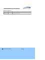
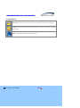
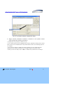
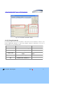
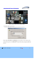
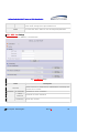
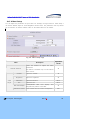
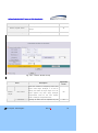
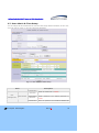
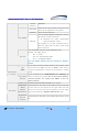
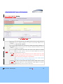
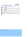
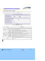
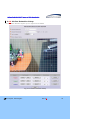
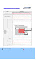
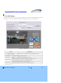
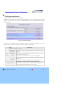
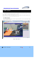
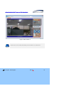
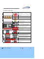
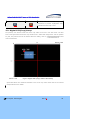
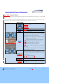
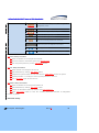
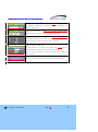
Configuration Guide of H.264 IP Cameras & Video Server Note This manual provides information to configure IP Camera and Video Server products through admin page settings. For the connection to the admin page enter http://[IP_address:http_port]/admin.htm into the address field of internet explorer. Refer to the manual of each product for product specific installation ` Configuration Guide of H.264 IP camera and Video Server Products Revision History Date 2011-10-11 Rev No 1.5 ⓒ 2011 Speco Technologies Description Creation of this Document Rev.1.5 2 Configuration Guide of H.264 IP camera and Video Server Products Indications: Warning : Death or Serious Injury will occur without complying with Warning. Caution : Operational Problem(Faulty & Malfunction) will occur without complying with Caution. Note : Technical information for User‟s Usage. ⓒ 2011 Speco Technologies Rev.1.5 3 Configuration Guide of H.264 IP camera and Video Server Products Contents Contents................................................................................. 4 1. Preparation for the connection................................................ 5 1.1. Product Installation ................................................................................. 5 1.2 PC Requirements ..................................................................................... 7 2. Admin Tool .......................................................................... 8 2.1. Access .................................................................................................. 8 2.2. Layout of Admin Page............................................................................ 11 2.3. Basic Setup ......................................................................................... 12 2.4. Network Setup ..................................................................................... 14 2.5. 802.1x Setup ....................................................................................... 16 2.6. Video Setup ......................................................................................... 18 2.7. User Admin & Time Setup ...................................................................... 21 2.8. Sensor & Capture Setup ........................................................................ 24 2.9. E-Mail & FTP Setup ............................................................................... 27 2.10. Alarm Device Setup ............................................................................. 29 2.11. Motion Detection Setup ........................................................................ 31 2.12. PTZ Setup.......................................................................................... 34 2.13. Upgrade & Reset ................................................................................. 36 2.14. Status Report ..................................................................................... 39 3. Web Viewer ........................................................................ 40 3.1 Web Viewer .......................................................................................... 40 3.2 Basic Control Key................................................................................... 42 3.3. Digital PTZ(Crop) Setup ......................................................................... 43 3.4. PTZ Control Menu ................................................................................. 44 4. Trouble Shooting & Tips ....................................................... 49 4.1. Trouble Shooting for Post-Installation ....................................................... 49 4.1.1. No Channel Name and No Video & “Response Timeout” Message ............................ 49 4.1.2. No Video under normal Connection (Only Frame of Web Viewer) ............................ 50 4.2 Trouble Shooting for Post-Normal Connection ............................................. 50 4.2.1. For slow Video Movement .................................................................................. 50 4.2.2. For the dull image and green, pink dots .............................................................. 51 4.2.3. For the mosaic phenomenon on video ................................................................. 51 ⓒ 2011 Speco Technologies Rev.1.5 4 Configuration Guide of H.264 IP camera and Video Server Products 1. Preparation for the connection 1.1. Product Installation Brief information for rapid installation is provided in this section. For more detailed information, you are recommended to refer to pertinent documentations provided with the product. 1. Apply Power to the device and connect with Network. AC adapter which is compliant to the specification for products should be used. Misuse of power supply can cause damage to products. Speco Technologies assumes no responsibility for misuse of the power supply. - Non-Standard Power Connection will cause critical damage to products. - Varieties of power supplying option are provided for each of the product. Please refer to the manual of each specific product for available option. 2. Install “IP-Installer (Ver.3.0.1 or above)” and “Speco-NVR (Ver.5.0 or above)” on your PC. Speco-NVR installation also includes IP-Installer installation. Detailed information for installing these programs can be found in [Speco-NVR User’s Guide], respectively. 3. Assign IP address to the product using IP installer. Identify the type of the network environment and set up IP address. If network type is xDSL or Cable modem you need supplementary information provided by your ISP. < Quick IP Installer Installation Guide > A. Starting IP Installer To starting IP Installer, select “Start Up” “Programs” “Speco Technologies” “IP Installer” at the Windows task bar. B. Find the Device for the Configuration Click on “Refresh” button to list up all IP Products (IP Cameras or Video Servers) connected on the same network with the PC and identify the products with MAC Address. ⓒ 2011 Speco Technologies Rev.1.5 5 Configuration Guide of H.264 IP camera and Video Server Products Fig 1-1. IP installer Network Configuration Setup C. Assign network parameters needed for connection to the product. Please follow through the following procedures. a. Double click on a product you want to set up. b. The selected product will be highlighted and network parameter settings will be shown. Each product can be identified with unique MAC address. Refer to the following figure for an example. c. If you want to change or initiate the network settings, fill in the fields with white background (the fields surrounded by red rectangles below) with proper values. d. Once you fill in the fields, click on “Set” to initialize the product with new settings. ⓒ 2011 Speco Technologies Rev.1.5 6 Configuration Guide of H.264 IP camera and Video Server Products Fig 1-2. IP installer Parameter Setup 1.2 PC Requirements AV streaming data received from IP camera or video server can be decoded or stored in a PC running SPECO-NVR program or other CMS program. Minimum requirement of the PC is recommended as in the following table. Class Recommended Spec CPU Intel Dual Core 3Ghz or Higher RAM 2GB or Higher Graphic Card 256MByte Graphic Memory or Higher Network 100Mbps or Higher OS Windows XP / Windows 7 ⓒ 2011 Speco Technologies Remarks Res. : 1600x1200 or Higher Rev.1.5 7 Configuration Guide of H.264 IP camera and Video Server Products 2. Admin Tool The operational condition of the IP cameras and video servers can be set up over the network. This chapter describes general information of setting up these products over the network. The products covered include H.264 IP Cameras and Video Server products. 2.1. Access Access to Admin Tool is available using Internet Explorer and exclusive “Speco-NVR”. 1. Assess using Internet Explorer Type in the connection address of the product in the address field of the Internet Explorer as followings: http://[IP address of the product]/admin.htm For the use of Port-forwarding, change the HTTP Port as below. http://[device IP address]:[HTTP port]/admin.htm 2. Access using exclusive Speco-NVR Select Video Channel in the viewing window of “Speco-NVR”. Selected Video Channel will be highlighted. Click button on the right side of the display screen. Upon connection, internet explorer starts to initiate the admin page. ⓒ 2011 Speco Technologies Rev.1.5 8 Configuration Guide of H.264 IP camera and Video Server Products Fig 2-1. Access to Admin Page using Speco-NVR 3. Input User Name and Password. Accessing to Admin Page is required to insert User Name and Password. Factory default “User Name” and “Password” are set as “admin” and “1234”, respectively. Click on “OK” button to enter into the Basic Setup page of Admin mode. If you have changed the username and password of the Administrator, you must log on with the changed username and password. ⓒ 2011 Speco Technologies Rev.1.5 9 Configuration Guide of H.264 IP camera and Video Server Products For secured security, it is recommended to change the User Name and Password during the installation. For the details, refer to the [User Admin & Time Setup]. Once User Name and Password are forgotten, it is required to restore the Factory Default Value as “admin” and “root” by pressing the Factory Default Button for about 5 sec while power is applied. All Setting parameters will be restored with Factory Default Values. ⓒ 2011 Speco Technologies Rev.1.5 10 Configuration Guide of H.264 IP camera and Video Server Products 2.2. Layout of Admin Page Upon initiation of the admin page, the screen similar to the following picture will be shown. The left side of the admin page shows various admin page menus, while the right side shows the settings of selected admin menu. Click each of the menu items at the left to go into specific admin page. Fig 2-2. Layout of Admin Page Once click on “Live” button, it will close Setting Page and switch to Web Viewing Mode. Select the language of your preference from drop down list. ⓒ 2011 Speco Technologies Rev.1.5 11 Configuration Guide of H.264 IP camera and Video Server Products 2.3. Basic Setup Setup the basic parameters for the operation of the product. Fig 2-3. Basic Setup Class Description Logical name of the product. It is same as the one set-up by IP- System Name installer. You can reassign the logical name. The system name will be shown in the connection through Speco-NVR. Screen Capture in Web Viewer Designate the folder to save captured image in Web viewer when click Capture Button ( ⓒ 2011 Speco Technologies ). Rev.1.5 12 Configuration Guide of H.264 IP camera and Video Server Products Select the type of input audio. Audio Input Selection Select Line In to use Line-out from audio device. Select Mic to use microphone. Maximum four different video profiles can be transmitted through Profile different way. E-Mail Profile is used only for transmitting E-Mail on every event trigger. Max Upload Rate Video Encoding Type Resolution Frame Rate Assign maximum bandwidth of the uplink for the network connected to device. Assign video codec for the profile. Either H.264 or MJPEG can be chosen. Assign Resolution of Video Transmission for each profile. Assign video frame rate. You can improve picture quality by lowering frame rate for the same bandwidth.. Assign the Resolution & Position of Digital PTZ. Video Quality & Digital PTZ Bandwidth (Crop) Control “(0,0)” means the position of Video and “176x128” means the size of Video. Position and Size of Digital PTZ Image can be changed on Web Viewer or Speco-NVR. Codec Performance Occupation The performance demand and the total performance of the Codec are shown. The values are updated when the setting is stored. Error message will be popped up if the performance demand exceed the total performance. Assign Video Rate bandwidth for transmitting video data. Even the Higher bandwidth is, the better video quality is, if it exceed the max. speed of Upload, normal video transmission will be interrupted. In cans of disconnection or mosaic of Video Image, reduce this value. Auto Rate Video Rotation Save Assign bandwidth for transmitting audio data with 32K. If not required, you can save unnecessary bandwidth by selecting “NA”. Rotate Video Image by Up-Side Down with 180o. You must click “Save” button to save all configured parameters. ⓒ 2011 Speco Technologies Rev.1.5 13 Configuration Guide of H.264 IP camera and Video Server Products 2.4. Network Setup Setup the network parameters appropriately in accordance with your network environment. Many of the parameters in this page are same as those set up by “IP-Installer”. Fig 2-4. Network Setup Class IP Assign Type Description The network types supported by the products are LAN(fixed IP), PPPoE, and DHCP(automatic IP allocation) Static IP ⓒ 2011 Speco Technologies When the network environment is fixed IP, select „LAN‟ Rev.1.5 in the 14 Configuration Guide of H.264 IP camera and Video Server Products Setup network type, and input the IP address, Subnet Mask, Gateway, DNS1 and DNS2. Ask your network administrator or ISP for the information. DNS2 is used when DNS1 does not work. When the network environment is PPPoE and IP address is assigned PPPoE Setup automatically, select „PPPoE‟ in the network type. Next, fill in the „User Name‟ and „Password‟ fields with the values given by your ISP. When the DHCP server assigns IP address automatically, select DHCP Setup „DHCP‟ in the network type. Select this mode in case of Cable Modem. Clone MAC When some customers want to use Clone MAC, use this function. Each port should have a number below 65535. HTTP Port Change RTSP RTP HTTP port is used for the connection to the admin page. Default is 80. The RTSP port is used for transmitting real time audio/video data from the product. Default is 554. The RTP port is used for transmitting real time audio/video data from the product. Default is 6970. Multicast IP Address Range is 224.0.0.0 ~ 239.255.255.255. Address Multicast Port TTL The address is used for multi-casting real time audio/video data from the product. Default 224.1.1.1. The port is used for multi-casting real time audio/video data from the product. Default 6970. Define how many routers pass through the multi-casting. Default value is 0(Off). You can restrict the access to the admin page from IP addresses beyond certain IP address range. Restrict IP Filtering Administrator Check at this box to restrict log on to the admin page. Access Basic IP Input IP address of the PC which is intended to be used for log on to Address admin mode. You can register the product to the DDNS Server for name service. DDNS Client Check this box to use DDNS service. By checking Hostname your Hostname product can use domain name instead of numeric IP address. This feature is particularly useful when your product is using dynamic IP ⓒ 2011 Speco Technologies Rev.1.5 15 Configuration Guide of H.264 IP camera and Video Server Products address. Input the hostname for the service. Result shows message from Speco DDNS server. Save You must click “Save” button to save all configured parameters. 2.5. 802.1x Setup This is setup page for IEEE802.1x authentication. Fig 2-5. 802.1x Setup Class Description Activation Certificate CA Certificate Client Certificate Private Key ⓒ 2011 Speco Technologies Check at the box to enable 802.1x authentication. If checked, this product acts as a client. Certificate for server verification Certificate for client verification Private Key of Client Rev.1.5 16 Configuration Guide of H.264 IP camera and Video Server Products Select EAP type and configure Sub Fields Select EAP type to choose authentication method. In order for authentication to be successful, the client and the server must use the same authentication method. Fields used by each method are below. EAP type EAP-MD5 : Username, Password EAP-TLS Setup : CA Certificate, Client Certificate, Private Key, Username, Private Key Password PEAP : CA Certificate, Username, Password EAP-TTLS : CA Certificate, Username, Password Username Account name of client Password Password for Username Private Key Password Save ⓒ 2011 Speco Technologies Password for Private Key You must click “Save” button to save all configured parameters. Rev.1.5 17 Configuration Guide of H.264 IP camera and Video Server Products 2.6. Video Setup You can adjust the parameters of input video. For example, the figure below is Video Setup a nd Camera Module Adjust of H.264 MegaPixel camera series. The parameters will vary followi ng the selection of camera modules. Refer to the tables below for the details. Fig 2-6. Video Setup Page Class Applicable Description Select Channel Selection the channel to Model adjust the video parameters. This feature is available only in multi channel All video servers. Contrast Adjust the contrast. All Brightness Adjust the brightness. All Video Saturation Adjust the saturation. Adjust Hue OSD Time Display OSD Menu Control ⓒ 2011 Speco Technologies OS101 Adjust the hue. Enable/disable OS101 OSD time display and designate the position of the OSD. Enter to OSD menu for camera configuration Rev.1.5 All OB1 18 Configuration Guide of H.264 IP camera and Video Server Products Save Restore original values Camera Module Adjust Save the parameters All Click on “CONFIRM” to restore the default settings. Click on “GO” to adjust the camera module. All All Fig 2-6-1. Camera Module Setup Class Applicable Description Model When the camera is acquiring video from object under bright backlight, it is hard to Module BLC Control Adjust identify the details of target object since the object appears very dark. Apply backlight MP compensation mode for this case. Default mode is backlight compensation Off. DC Level ⓒ 2011 Speco Technologies Opening of IRIS can be adjusted by DC Rev.1.5 All 19 Configuration Guide of H.264 IP camera and Video Server Products voltage. It will be activated only with supported product. When the camera is acquiring video from object under bright backlight, it is hard to BLC Control identify the details of target object since the object appears very dark. Apply backlight MP compensation mode for this case. Default mode is backlight compensation Off. DSS (Digital Slow Shutter) Control WhiteBalance Sharpness Activate or Deactivate the use of DSS. It will provide enhanced image in the low light MP condition. Select the white balance mode : Auto, Outdoor, Indoor MP Adjust the sharpness of the video. MP Color Control Adjust the color. MP Filter Turn On Adjust the IR filter level by selecting from Illumination(Night to Day) low, normal and high. Default value is Power Line Select Frequency of Power. Normally 50Hz is Frequency for PAL region and 60Hz is for NTSC region. Restore Original Values Save Back MP normal. Click on “CONFIRM” to restore the default settings. Save the settings. MP All All Click on “BACK” to go back to Video Setup page. All The settings on this table are not applicable on Video Server (OS101) as it encode the analog video and transmit it. ⓒ 2011 Speco Technologies Rev.1.5 20 Configuration Guide of H.264 IP camera and Video Server Products 2.7. User Admin & Time Setup You can change the ID and Password of users and also assign different attributes to each user. You must click the “Save” to save all configured parameters. Fig 2-7. User Admin & Time Setup Class Description Administrator User Management Username Administrator Administrator Admin password : “1234”. Administrator ⓒ 2011 Speco Technologies Admin ID. Default ID is “admin” password. The default password is Enter the password once more to confirm the Rev.1.5 21 Configuration Guide of H.264 IP camera and Video Server Products Confirm password. Password User Name Password Enter the user ID you want to add. Up to 100 users can be registered in the product. Enter the user password. You can assign different privileges to users in the access to system resources. User Addition Attributes Attribute are Audio, Bi-directional Audio and Pan/Tilt control. For example, if you want a specified user to hear the audio from the device, check Audio in the check box. You can identify “User ID” and its “Attributes” here. Format : User ID[A, BA, P] : A – Audio, User List BA – Bi-Directional Audio, P – PTZ(Pan/Tilt/Zoom) You can delete specific User by clicking on “Delete” button. If you want to restrict viewing access to the product, check YES at the box left to “Yes” and click on “Save”. Users need to SAVE input ID and password to connect to the product in viewing mode. Authentication for Viewing If you uncheck for the “Authentication for Viewing”, all If No, default users can access the product with the same default attribute. attribute Checked attributes are enabled. Click “Save” to save the default attribute. Time Setup Current Time It shows you the current time kept in the product. Synchronize Synchronize the time kept in the product with the time kept with an in time server on the internet at the right. When the time Internet server is out of the reach from the product, you can assign Time Server Synchronize With this Computer ⓒ 2011 Speco Technologies time server by filling in “Specific Time Server” field. Synchronize the time kept in the product with the time in the PC. Rev.1.5 22 Configuration Guide of H.264 IP camera and Video Server Products Time Set Manually Save Set the time manually. Fill in the fields with desired formats. You must click “Save” button to save all configured parameters. If you lost Administrator’s ID and password, the only means of recovery is to reset the settings to factory default, but then you lose your previous settings. ⓒ 2011 Speco Technologies Rev.1.5 23 Configuration Guide of H.264 IP camera and Video Server Products 2.8. Sensor & Capture Setup This is the setup page for sensors and video capture conditions. Captured video can be sent to user by FTP or (and) E-mail, or stored on local HDD. Fig 2-8. Sensor & Capture Setup Class Description Select sensor type. There are two types of sensors which are Sensor Setup Sensor 1 Normal Open and Normal Close. - NC (Normal Close) : Contact Points are normally closed. ⓒ 2011 Speco Technologies Rev.1.5 24 Configuration Guide of H.264 IP camera and Video Server Products - NO (Normal Open) : Contact Points are normally parted Name Input logical name for the sensor. It sets the condition of video capture for FTP, E-mail or storing in the local storage. The product supports 2 types of conditions which are mutually independent. Activate/Deactivate the transmission of the Sensor Triggered Sensor Video Setup Selection Video and Audio. After selecting Capture Condition, you should select Transmission Method. Motion Detection Selection Activate/Deactivate the transmission of the Motion Detection Triggered Video and Audio. After selecting Capture Condition, you should select Transmission Method. Select transmission method of Event Triggered Video and Audio. E-Mail Transmission FTP Transmission Transmission Method Built-in Storage Play Alarm Sound Motion Set Attached File Type Transmit to address of “Receive E-Mail Address” configured at [E-Mail & FTP Setup]. Transmit to “FTP Server” configured at [E-Mail & FTP Setup]. Store the Video in the built-in SD Card. Play alarm sound when event occurs. This function is supported only in O2S1 camera with Built-In Speaker. Move to Setup Menu for setting Motion Detection. Select the type of file which is attached in the E-Mail. Set to transmit the Pre/Post recorded Video by the event occurred Pre/Post E-Mail / time. Totally 20 seconds of buffer can be allocated for use, FTP according to Pre-Recording Setup, Post-Recording Setup will be Recording Time automatically calculated. Built-in Storage Schedule Set to record the Pre/Post Video in the built-in Storage by the event occurred time. Pre-Recording is available to set 5 ~15 sec, Post-Recording is available to set 19 ~60 sec. Set the schedule to start the recording based on configured event. ⓒ 2011 Speco Technologies Rev.1.5 25 Configuration Guide of H.264 IP camera and Video Server Products Alarm Check each desired column and select “Add”. Then click Save to save the Setup setup. You can confirm all setup by the color displayed on calendar. Type Date Select the need to be configured operation method among Sensor, Motion Detection and constant recording. Select the Date on which Alarm go off. Set the Time on which Alarm go off. Time Time is available to set on every 30 minutes from 00:00 to 24:00. Save ⓒ 2011 Speco Technologies You must click “Save” button to save all configured parameters. Rev.1.5 26 Configuration Guide of H.264 IP camera and Video Server Products 2.9. E-Mail & FTP Setup Fig 2-9. E-Mail & FTP Setup If you check this, the IP address will be sent via E-mail whenever Notify for IP the IP address changes. It is sent to the E-mail address set in Change Recv E-Mail Address “Recv E-Mail Address”. E-Mail address for receiving file created from Motion Detection or Alarm Device as well as for receiving changed information when IP Address is changed. Fill in this field with active and valid e-mail address to identify sender of the e-mail. If not set, the sender address will be set to E-Mail Setup Return EMail Address “support@net-video,net”. Note that the e-mail message from the product might not pass through the SPAM filter of the receiver‟ s e-mail server, when this field is not filled in with active e-mail address. To avoid this kind of problem, please set the return E-Mail address identical to User Name of external SMTP Server. Internal In case of using Web Mail Service without SMTP Server, select SMTP “Internal SMTP Use”, insert appropriate E-Mail address to prevent Server Use SPAM Filtering at the receiver‟s mail server. ⓒ 2011 Speco Technologies Rev.1.5 27 Configuration Guide of H.264 IP camera and Video Server Products External SMTP If you are using external SMTP Mail server, fill in the fields with provided SMTP related information. Server Use Check it only when SMTP server requires Use of SSL for Log On. Use SSL If it is setup for SSL non-supported server, E-Mail transmission doesn‟ t work. E-Mail Port Set it only when E-Mail Server is used with change of default port. Num Setup IP address, Username, Password and Directory of FTP server FTP Server Setup to send captured video data. Default FTP port number is 21, and it can be changeable for environments. Save You must click “Save” button to save all configured parameters. ⓒ 2011 Speco Technologies Rev.1.5 28 Configuration Guide of H.264 IP camera and Video Server Products 2.10. Alarm Device Setup Setup alarm device to go off according to the condition of sensor or motion detection. For the operation of Alarm Device, sensor needs to go off at least for 2 sec. Fig 2-10. Alarm Device Setup Class Description You can test various alarm device such as Siren, light bar etc connected to Alarm Device relay port of product using On/Off button. Test ON On the alarm output (close the relay contact) OFF Off the alarm output (Open the relay contact) Setup the operational condition of alarm device Alarm Device Name Designate the Name of Alarm Device for classification Operational Sensor Trigger alarm device according to sensor input. Motion Trigger alarm device when motion is detected on the video. Condition Duration Save ⓒ 2011 Speco Technologies Set the duration of Alarm annunciation.. You must click “Save” button to save all configured parameters. Rev.1.5 29 Configuration Guide of H.264 IP camera and Video Server Products ⓒ 2011 Speco Technologies Rev.1.5 30 Configuration Guide of H.264 IP camera and Video Server Products 2.11. Motion Detection Setup Set the motion detection regions. Up to 3 regions can be defined. Fig 2-11. Motion Detection Setup ⓒ 2011 Speco Technologies Rev.1.5 31 Configuration Guide of H.264 IP camera and Video Server Products Class Description Channel Selection Select the channel to configure the motion detection zone. (Channel selection is available only on multi channel products.) Set the sensitivity of motion detection for each channel. Channel Sensitivity 1 is the most sensitive, while 10 is the least sensitive. (Default : 6) Note that false motion alarm can be generated under noisy video when the device is set to be unnecessarily sensitive. Up to 3 motion detection zones can be configured. Enable each zone by checking at the box at the left of each Region. Checking at the box is prior to setup of motion detection region. <Region Setup > 1. “Start” -> Region Selection Start Region Motion 1, 2, 3 Detection Area Motion Detection Region End Setup 2. “End” -> Region Selection Color of Region: Region 1: Red, Region 2: Green, Region 3: Blue Select Click on this button and click on desired rectangle to add or delete a boxed region to the motion detection zone. This value controls the sensitivity of each region. 1 is the most sensitive and 100 is the least sensitive.(Default is Percentage 50%) Note that false motion alarm can be generated under noisy video when the value is small. Delete ⓒ 2011 Speco Technologies Clears the start & end point to (0,0) & (0,0) Rev.1.5 32 Configuration Guide of H.264 IP camera and Video Server Products Save ⓒ 2011 Speco Technologies You must click “Save” button to save all configured parameters. Rev.1.5 33 Configuration Guide of H.264 IP camera and Video Server Products 2.12. PTZ Setup This is the setup page for PTZ. This page is available on the models including speed dome camera or PT device. You can configure PTZ parameters using Web Viewer or Speco-NVR, too. Fig 2-12. PTZ Setup Class Description Channel Selection PTZ Model Selection PTZ Device ID PTZ Baud Rate Activated only for Multiple Channel supported Product Select Protocol used by PTZ Camera. Delete Delete the selected PTZ Protocol. Insert the ID of PTZ Device. Save the ID by clicking “SAVE”. If PTZ ID doesn‟ t accord, it won‟ t operate properly. Set the RS-485 Baud Rate for PTZ Operation. If Baud Rate doesn‟ t accord, it won‟ t operate properly. ⓒ 2011 Speco Technologies Rev.1.5 34 Configuration Guide of H.264 IP camera and Video Server Products Speed PTZ Device Operation Test Activate the Speed Control by Slider. Step Activate the Step Size Control by Slider. PAN Control Speed or Step for Left/Right Movement. TILT Control Speed or Step for Up/Down Movement. ZOOM Control Speed or Step for Zoom In/Zoom Out. ⓒ 2011 Speco Technologies Rev.1.5 35 Configuration Guide of H.264 IP camera and Video Server Products 2.13. Upgrade & Reset You can upgrade the device via the IP network. Upgrade is a process to renew the System Software stored in the non-volatile memory of the system. You must restart the system by “System Restart” to run the system with the upgraded system software. Fig 2-13. Upgrade & Reset Contents of the upgradable system component should be downloaded from Speco home page. Please check the latest Version before the system upgrade is performed. Class Description Upgrade the system manually. System S/W Upgrade Manual Boot loader Upgrade Upgrade Camera F/W Upgrade Upgrade the system software installed on the product via the network. Upgrade the boot loader installed on the product after achieving from Technical Support Team. For normal case, Boot Loader is not required for Upgrade. Only for required case, it is performed to upgrade Camera Module F/W. (It will be automatically activated only for available models) Re-initialize the network camera to factory default state. Factory Default By checking on a Radio button “Except Network Configuration”, you can preserve the parameters for the network. ⓒ 2011 Speco Technologies Rev.1.5 36 Configuration Guide of H.264 IP camera and Video Server Products For the remote upgrade, you must check “Except Network Configuration” to connect after the upgrade. Once all the values are set to factory default state, the product should be set-up again using IP-Installer. System Restart System will restart by clicking “CONFIRM”. After the Upgrade, you have to apply all upgraded points through system restart. Upgrade will change the F/W or other programs stored on system. You must perform “System Restart” to start system with all changed points. You must select “Except Network Configuration” to connect with the same connection parameters after performing the Factory Default. Once all the values are set to factory default state by performing Factory Default with “All”, the product should be set-up again using IPInstaller. ⓒ 2011 Speco Technologies Rev.1.5 37 Configuration Guide of H.264 IP camera and Video Server Products <Upgrade Procedure> Unless otherwise instructed, the owners of the device are recommended to upgrade the system when upgraded firmware is released using manual upgrade procedure. Manual Upgrade Procedure 1) Save the F/W which you get from the visiting Website or E-Mail enquiry to your PC. 2) Log on “Admin Tool”, select “Upgrade & Reset” menu. 3) Open the “Choose File” window by clicking “Browse..” to find F/W file for Upgrade. The file extension is “.ief”. 4) Click “Open” to select the F/W file, then “Choose File‟ window will be closed. 5) Once click “Install”, alert message box will pop up, then click “OK” button to transmit the F/W file to product. The required time for transmission will be dependent on network environment, In some cases, it will take few minutes. 6) Upgrade completion message will appear after the system upgrade has been completed. 7) Reboot device by performing “System Restart”. 8) After rebooting, log on to the product in admin mode again and click the “Status Report”. 9) Check the version number and release date of the firmware. Once the system is reset to the factory default state by system reset of the administrator, all the connection of the users might be disconnected. Since the connection is not recovered automatically, users should set up the connection manually with new connection information. ⓒ 2011 Speco Technologies Rev.1.5 38 Configuration Guide of H.264 IP camera and Video Server Products 2.14. Status Report It shows you system records since the system started. Fig 2-14. Status Report You can review the problems of each module and check whether the upgrade of System S/W is successfully completed as well as check the Ver. of currently used System S/W and Event. ⓒ 2011 Speco Technologies Rev.1.5 39 Configuration Guide of H.264 IP camera and Video Server Products 3. Web Viewer IP camera and video server provide video connection over the internet explorer. The web viewer might be dependently different based on products. Some models are provided with additional menu for PTZ Control. All H.264 IP cameras and 1 channel video server products provide Digital PTZ function. 3.1 Web Viewer “Fig 3-1” is Web Viewer Image of PTZ Non-Supported products, “Fig 3-2” is Web Viewer Image of PTZ Supported products. Fig 3-1. Web Viewer-1 ⓒ 2011 Speco Technologies Rev.1.5 40 Configuration Guide of H.264 IP camera and Video Server Products Fig 3-2. Web Viewer-2 Please refer to the section [PTZ Setup] for the details on the PTZ Menu. ⓒ 2011 Speco Technologies Rev.1.5 41 Configuration Guide of H.264 IP camera and Video Server Products 3.2 Basic Control Key Set On/Off of 2-Way Communication. Communication will Audio 2-Way Audio be when enabled activated. Save the Captured Image at BMP format. Rotate the Video with 180 Degree. Crop a certain part of Video. Digital PTZ is function of cut and transmit a certain part of video. Set the position of left top corner of the Digital PTZ Video/. Refer to [2.2.2 Digital PTZ Setup] Set the Resolution, Frame Rate of Digital PTZ Video. Max. Res is 800x600, Max. Frame rate is 30FPS. Start the transmission of Digital PTZ Video on Channel 4. Perform the Video access to each profile. #4 Profile will be used for Digital PTZ function. Disconnect the access to Video. Contrast & Brightness adjustment. The Value will be saved on PC. Volume Control & Audio Mute Control. Share the Audio Volume with PC. Adjust the size of video. Display the current status of each sensor. For the activated status, it will be redhighlighted. ⓒ 2011 Speco Technologies Rev.1.5 42 Configuration Guide of H.264 IP camera and Video Server Products Set On/Off the external device(Relay) connected to product. Highlighted color indicates that the relay is “On:. 3.3. Digital PTZ(Crop) Setup The position, size and the frame rate of the crop video can be set in the web viewer. The blue area in the figure below shows the crop window from a 1600x1200 image sensor. Set the position as (400, 300) and the size as the desired. After the setting, click on ( ) to start video transmission. Size of Digital PTZ Video Fig 3-3. Digital PTZ (Crop) Video & Size Setup Speco-NVR offers more advanced interface to the use of crop video. Please refer to the manual of Speco-NVR for the details. ⓒ 2011 Speco Technologies Rev.1.5 43 Configuration Guide of H.264 IP camera and Video Server Products 3.4. PTZ Control Menu You can control the PTZ of PTZ Supported model using the additionally marked menu on the Web Viewer. It will be available with OPTZ36XI/OPTZ36XO/O2S1, the functions which are not supported from the product will not work, so please check the supported functions of camera. Camera Position Control - Pan/Tilt Control - Zoom In - Zoom Out Focus on faraway point. Focus on near point. Open the OSD Menu for Camera Setup. On OSD Menu, use Up/Down buttons to navigate through the menu item on the screen. Depending on the situations, Left/Right buttons will perform one of the following. 1. Change parameter value in each submenu. 2. Increase/Decrease the numbered value. 3. Go into lower level on menu tree. 4. Execute the selected command. Please refer to Product Manual for more detailed OSD Menu. If the product can‟ t support the OSD menu, “Menu” button is disabled. Center the camera on the pointed area, so the pointed area on the video is located at the center of the video. - Left : Deactivated Status. - Right : Activated Status. Control the Iris. Set the Pattern for repeating the programmed movement. ⓒ 2011 Speco Technologies Rev.1.5 44 Configuration Guide of H.264 IP camera and Video Server Products Set the Tour for repeatedly moving to the designated preset. Set the Preset Position. Move to the designated preset position. Perform the configured pattern. Perform the configured scan. Stop the currently performed command. Control step size of PAN/TILT movement Display preset list. Do home positioning (search center position. 1. Preset Setup Procedure a. Select the Number to be assigned as Preset ID. b. Move the camera to the desired point using Pan/Tilt/Zoom. c. Save the preset position by clicking “SET PRST” button. 2. Tour Setup Procedure a. Select Number to be assigned as Tour ID. b. Open OSD Menu by clicking “SET TOUR” button. c. Designate the preset number for use and click the “GOTO PRST” to save the preset. d. Repeat procedure “c” to assign a series of preset positions to the tour. d. Click “SET TOUR” again to save the tour. 3. Pattern Setup Procedure a. Select the Number to be assigned as Pattern ID. b. Open OSD Menu by clicking “SET PTRN” button. c. Perform the Movement Pattern of Camera using Pan/Tilt/Zoom. d. Click “SET PTRN” button to save the currently performed command as designated number of pattern. Detailed Setup ⓒ 2011 Speco Technologies Rev.1.5 45 Configuration Guide of H.264 IP camera and Video Server Products Use to change the designated Tour Setup. Set the setting value for “Tour No. / Step No. / Setting Value” sequentially and set them on the camera by clicking “Set” button. Use to change the setting of configurable Auto Scan on OSD Menu. Set the Starting & Ending Point of Scan Function. With standard of coordinate value displayed on the bottom, if it is set incrementally from small to large value, it will rotate with exterior angle, if it is set decrementally from large to small value, it will rotate with interior angle. Endless Function of OSD Menu should be off. When Endless function is on, select the direction of rotation of camera. Activate/Deactivate the Endless function. Setting status is only checkable on OSD Menu. Activate/Deactivate Flickless function. Activate/Deactivate BLC function. Activate/Deactivate WDR function. It will be available with a certain model limitedly. Activate/Deactivate DSS function. Reverse the Left/Right side of Video. Reverse the Top/Down side of Video. ⓒ 2011 Speco Technologies Rev.1.5 46 Configuration Guide of H.264 IP camera and Video Server Products When Tilt operation pass over the limited 90 degree, it will turn the camera with 180 degree for the continuous Tilt operation. Activate/Deactivate the Digital Zoom function of Camera Module. Change the setting parameter of Camera Module. After setting the parameters for each column, click the “SET” to set on the camera. Set and Change the PTZ Operational Setup for Alarm Input. Set the N.O. / N.C. as Input against Input Sensor, then consequently select operational PTZ Command and click “SET” to save. Activate/Deactivate the Alarm Setup of OSD Menu. This Setup should be on activated status for the operation of alarm. Add and Change the Setup for Privacy. Select the number of change-desired Privacy Setup, and click “SET”, then Privacy Setup will be displayed on the screen as OSD. DISPLAY Display the Privacy-Protected area on the screen. Move and adjust the protected area and size displayed on the screen by selecting MOVE and ADJUST. Select the “ADJUST” to control the size and click ACTION the Focus Far( ) button, then control the size using PT Direction Key, then save it by clicking Focus Far button again. SAVE ⓒ 2011 Speco Technologies You must click “Save” button to save all configured parameters. Rev.1.5 47 Configuration Guide of H.264 IP camera and Video Server Products Change the area of Sector configured on OSD Menu. All Characters displayed by Sector function are changeable only through OSD Menu. Delete the information of Preset, Tour, Pattern, Privacy, Sector configured on the camera selectively or on the whole. Display the information of Camera ID, Preset ID, Sector, Coordinate selectively on the screen as OSD. Check all desired column and click “SET” to display. Lock the access to OSD Menu. Set the password by inputting the number from 1~200 and you can activate and deactivate the System Lock Setup. Perform the Goto Preset to enter into OSD Menu Under the locked status. Restart the Camera Module and perform the operational test. ⓒ 2011 Speco Technologies Rev.1.5 48 Configuration Guide of H.264 IP camera and Video Server Products 4. Trouble Shooting & Tips 4.1. Trouble Shooting for Post-Installation 4.1.1. No Channel Name and No Video & “Response Timeout” Message The status of abnormal communication with product. 1. Check the operational status of network. a. Check the connection status of external network. Open Internet Explorer, try to connect to any server as below; e.g.> http://www.yahoo.com or open the MS-DOS prompt and type the following; e.g.> Ping www.yahoo.com The response like “Reply from~” means that the connection status of network is working properly. b. Once you check the external connection status, input as below to check the connection with product. Ping [Product’s IP Address] e.g.> ping 192.168.1.112 The response like “Reply from~” means that the connection status of product is working properly. 2. Once you don‟ t get the response like “Reply from~” during network operational test, you have to check the status of network cable, power cable, network setup step by step. ⓒ 2011 Speco Technologies Rev.1.5 49 Configuration Guide of H.264 IP camera and Video Server Products 1 2 4.1.2. No Video under normal Connection (Only Frame of Web Viewer) The status of abnormal handling of video transmission or display. 1. Check the Video Source whether the video is properly applied into the product. (Video Server) 2. Check whether there is firewall(router) between the product and the client. If it is blocked by firewall, change the setup of firewall. 3. For the use of firewall(or router) setup or port forwarding, set the port of Web Port(Default : 80), and Streaming Port (Default : 554). Detailed information will be different from each routers, refer to the manual or enquire to the network administrator. 4.2 Trouble Shooting for Post-Normal Connection 4.2.1. For slow Video Movement In Basic Setup of Admin Mode, lower the “Quality”. High quality means more data. You can also set the “Max. upload rate” to higher value. But this value must be lower than the maximum upload speed of your network. For example, if the maximum uploading bandwidth of the network is 400Kbps, set the total “Max. upload rate” as 384Kbps. If you set it higher, the video image can be corrupted with artifacts. Ask your network manager or ISP for maximum uploading bandwidth of the network. ⓒ 2011 Speco Technologies Rev.1.5 50 Configuration Guide of H.264 IP camera and Video Server Products 4.2.2. For the dull image and green, pink dots This could be caused by performance limitation of the PC. Do not run too many programs while running viewer program. The other reason could be missing data in the transmission from the device. 4.2.3. For the mosaic phenomenon on video Mosaic phenomenon occurs when not enough network bandwidth is available considering the resolution and frame rate of the video. Example is 704x480 video with low Max. upload rate. Users are recommended to adjust resolution and frame rates to lower values for lower bandwidth network. ⓒ 2011 Speco Technologies Rev.1.5 51