1
M E R I D I A N
S U B W O O F E R
U S E R
G U I D E
Meridian Subwoofer User Guide
#$
2!$)/
$6$
&UNCTION
4OP-ENU
!58
$)3#
4!0%
46
#!",%
3!4
6#2
6#2
'!-%
/&&
0OWER
0AGE
!UDIO
0AGE
%NTER
3LOW
/PEN
-ENU
2ETURN
2EPEAT
3ETUP
2ECORD
"AND
!NGLE
i
3UBTITLE
$30
3TORE
#LEAR
0HASE
!"
/3$
$ISPLAY
-UTE
PREFACE
Important safety instructions
•
•
•
•
Read the instructions.
Keep these instructions.
Follow all instructions.
Do not use this apparatus near
water.
• Clean only with a dry cloth.
• Install only in accordance with
the manufacturer’s instructions.
• Refer all servicing to approved
service personnel.
Safety warnings
WARNING: TO REDUCE THE RISK OF
FIRE OR ELECTRIC SHOCK, DO NOT
EXPOSE THIS APPARATUS TO RAIN
OR MOISTURE
• Do not expose the speakers to
dripping or splashing.
• Do not place any object filled with
liquid, such as a vase, on the
speakers.
• Do not place naked flame
sources, such as lighted candles,
on the speakers.
To avoid overheating
• Leave at least 10cm around the
equipment to ensure sufficient
ventilation.
Do not position the unit:
• In direct sunlight.
• Near heat sources, such as a
radiator.
• Directly on top of heat producing
equipment, such as a power
amplifier.
ii
To avoid interference
Do not position the unit:
• Near strong magnetic radiation.
• Near to a television, or where
connecting cables may be subject
to or cause interference.
Radio interference
FCC Warning: This equipment
generates and can radiate radio
frequency energy and if not
installed and used correctly in
accordance with our instructions
may cause interference to radio
communications or radio and
television reception. It has been
type-tested and complies with the
limits set out in Subpart J, Part 15 of
FCC rules for a Class B computing
device. These limits are intended to
provide reasonable protection
against such interference in home
installations.
EU: This product has been designed
and type-tested to comply with the
limits set out in EN55013 and
EN55020.
Contents
Introduction
1
Meridian subwoofers
2
Sample configurations
3
Specification – SW1600
4
Specification – SW5500
6
Available accessories
8
Setting up the subwoofer
9
Unpacking
10
Installing the subwoofer
11
Positioning the subwoofer
14
Connecting the subwoofer
15
Connecting the subwoofer to other
equipment
17
Adjusting the subwoofer
20
Troubleshooting
23
Troubleshooting
24
Service and guarantee
25
Index
27
iii
PREFACE
Copyright and acknowledgements
Sales and service in the UK
Sales and service in the USA
Meridian Audio Ltd
Latham Road
Huntingdon
Cambridgeshire
PE29 6YE
England
Meridian America Inc
8055 Troon Circle
Suite C
Austell
GA30168-7849
USA
Tel (01480) 445678
Fax (01480) 445686
Tel (404) 344 7111
Fax (404) 346 7111
World Wide Web – http://www.meridian-audio.com
Designed and
manufactured in the UK by
Meridian Audio Ltd
Latham Road
Huntingdon
Cambridgeshire
PE29 6YE
England
Copyright © 2005 Meridian Audio Ltd.
Part no: SUBU/1
Boothroyd|Stuart Meridian, Meridian,
This guide was produced by:
Meridian Digital Theatre, Meridian
Human-Computer Interface Ltd,
Lossless Packing, MHR and MLP are
http://www.interface.co.uk
registered trademarks of Meridian
Audio Ltd.
MHR: This product incorporates
copyright protection technology covered
by certain patent applications and
intellectual property of Meridian Audio
Ltd. This technology is provided for the
express purpose of securely containing
copyright audio within the Meridian
System only. Reverse engineering or
circumvention of this protection is
strictly prohibited.
iv
Introduction
Welcome to the Meridian SW1600 and SW5500 subwoofers.
This User Guide provides full information about using the subwoofers
in conjunction with your other equipment, to achieve the superb
results you can expect from them.
#$
2!$)/
$6$
&UNCTION
4OP-ENU
!58
$)3#
4!0%
46
#!",%
3!4
6#2
6#2
'!-%
/&&
0OWER
0AGE
!UDIO
0AGE
%NTER
3LOW
/PEN
-ENU
2ETURN
2EPEAT
3ETUP
2ECORD
"AND
!NGLE
1
3UBTITLE
$30
3TORE
#LEAR
0HASE
!"
/3$
$ISPLAY
-UTE
INTRODUCTION
Meridian subwoofers
The Meridian SW1600 and SW5500 combine the finest materials with state
of the art design to create what we believe are the ultimate subwoofers,
emphasising extreme bass, depth, clarity, control, and articulation.
Each subwoofer provides both digital and active analogue inputs, allowing
them to be connected either to a digital surround controller or digital
source with a digital coax output, or to an analogue preamplifier or
surround controller with either phono or balanced outputs.
Digital Signal Processing
The subwoofers employ 96kHz/24bit digital to analogue conversion and
accept digital inputs up to 96kHz including those carrying MHR signals.
Separate analogue and digital power supplies are used to feed the
subwoofer’s precision electronic circuits, ensuring that both high and low
power sections receive continual smooth supply.
If you are using the subwoofers with a digital source, such as CD or DVD,
the signals remain in digital form until the last possible stage.
Subwoofer drivers
The subwoofers are based on 300mm (12") high-efficiency long-throw
custom drive bass units. The SW1600 uses a single driver, and the SW5500
uses two drivers in a single enclosure. In each case the enclosure is sealed
for maximum flexibility of positioning.
Power amplifiers
The speakers are driven by Class G high efficiency ultra low output
impedance amplifiers. The combination of idealised magnetic design,
careful star earthing, and very fast output devices gives the amplifiers
extremely low noise and fast bass, optimised for both music and movie
soundtracks.
The whole electronic assembly is supplied from substantial toroidal
transformers feeding high-quality, audiophile-grade capacitors.
Cabinet
Each subwoofer is carefully constructed from 22mm MDF with inert basket
bracing and resin damping to produce an ultra-rigid cabinet.
The subwoofer is finished with a 6mm annealed glass plate top and thick
veneered MDF sides bolted to the main cabinet, giving extremely low levels
of cabinet resonance.
2
INTRODUCTION
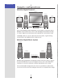
Sample configurations
Meridian Digital Theatre™
$30(#
$30
$30
$30
$30
37
'$6$!UDIO4RANSPORT
/PEN
$ISPLAY
(OME
'!$6$0LAYER0REAMPLIFIER4UNER
wxy z{|
-/./ hij `ac -ORE
/N/FF
'$IGITAL3URROUND#ONTROLLER
#$
$ISPLAY
(OME
'!$6$0LAYER0REAMPLIFIER4UNER
$6$
#$
2!$)/
$33
!6
-ORE
/N/FF
Up to seven Meridian DSP loudspeakers can be used in conjunction with a
Meridian Surround Processor, such as the G68 Digital Surround Controller,
to create a digital surround system with superb music and cinema sound.
A SW1600 is ideal as a mono subwoofer for the system, to give exciting
cinema effects and added realism in DVD movies.
Meridian Digital Music System
-*xÓää
-*xÓää
37
37
'BIT#$0LAYER
/PEN
$ISPLAY
'#$0LAYER
(OME
wxy z{|
-/./ hij `ac -ORE
/N/FF
Meridian DSP loudspeakers include DSP volume and tone controls, and can
be connected directly to up to two digital sources, such as the G07 24-bit
CD Player, to create an extremely compact high-quality music system.
The recommended configuration for music is to provide two subwoofers,
one for each of the main left and right channels, for a superb stereo image.
3
INTRODUCTION
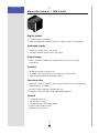
Specification – SW1600
Digital inputs
• 2 x cable inputs, 32-96kHz.
• PCM using IEC958, or MHR connection support with auto-detection.
Analogue inputs
• 3 x phono inputs: mono, left, right.
• 3 x XLR balanced inputs: mono, left, right.
Output stage
• Power amplifier: 150W Class G high efficiency ultra low output
impedance.
Acoustic
• Sealed enclosure; no port noise.
• 1 x 300mm (12") high-efficiency long-throw custom driver.
• Inert basket braced resin damped cabinet.
Characteristics
•
•
•
•
Distortion <0.01%, typically <0.02% up to full power at all frequencies.
Noise and hum <-72dBm.
Acoustic output typically >107dB spl @ 1m.
Frequency response within 3dB, 20Hz-400Hz (Bypass).
Control
•
•
•
•
•
2 x Meridian Comms.
Variable gain control.
Variable low pass filter 40Hz-150Hz.
Internal filter defeat switch.
Absolute phase switch.
4
INTRODUCTION
Cabinet
• Cabinet constructed from 22mm MDF.
• 6mm annealed plate glass top.
• 416mm x 416mm x 416mm (16.4" x 16.4" x 16.4") (W x H x D excluding
feet).
• 28kg (62lb).
Power
• 100/115/120V; 220/230/240V AC 50-60Hz.
• 20-500VA
Meridian Audio reserves the right to amend product specifications at any
time.
5
INTRODUCTION
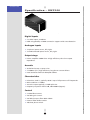
Specification – SW5500
Digital inputs
• 2 x cable inputs, 32-96kHz.
• PCM using IEC958, or MHR connection support with auto-detection.
Analogue inputs
• 3 x phono inputs: mono, left, right.
• 3 x XLR balanced inputs: mono, left, right.
Output stage
• Power amplifier: 300W Class G high efficiency ultra low output
impedance.
Acoustic
• Sealed enclosure; no port noise.
• 2 x 300mm (12") high-efficiency long-throw custom drivers.
• Inert basket braced resin damped cabinet.
Characteristics
•
•
•
•
Distortion <0.01%, typically <0.02% up to full power at all frequencies.
Noise and hum <-72dBm.
Acoustic output typically >110dB spl @ 1m.
Frequency response within 3dB, 20Hz-400Hz (Bypass).
Control
•
•
•
•
•
2 x Meridian Comms.
Variable gain control.
Variable low pass filter 40Hz-150Hz.
Internal filter defeat switch.
Absolute phase switch.
6
INTRODUCTION
Cabinet
• Cabinet constructed from 22mm MDF.
• 6mm annealed plate glass top.
• 788mm x 416mm x 440mm (31.1" x 16.4" x 17.3") (W x H x D excluding
feet).
• 50kg (110lb).
Power
• 100/115/120V; 220/230/240V AC 50-60Hz.
• 20-500VA
Meridian Audio reserves the right to amend product specifications at any
time.
7
INTRODUCTION
Available accessories
Each subwoofer is shipped complete with cables to enable it to be used in a
Meridian Digital Music System.
Other applications, and some advanced features, may require one or more
of the following accessories, which can be purchased from your Meridian
dealer:
• Additional S5 leads (8m and 14m).
• 511 S-patch box if connecting more than two DSP loudspeakers to a G68
Digital Surround Controller (not required with 861).
8
Setting up the subwoofer
This chapter explains how to install your subwoofer. It describes what
you should find when you unpack the subwoofer, how you should
connect it to your other audio equipment, and the siting constraints.
#$
2!$)/
$6$
&UNCTION
4OP-ENU
!58
$)3#
4!0%
46
#!",%
3!4
6#2
6#2
'!-%
/&&
0OWER
0AGE
!UDIO
0AGE
%NTER
3LOW
/PEN
-ENU
2ETURN
2EPEAT
3ETUP
2ECORD
"AND
!NGLE
9
3UBTITLE
$30
3TORE
#LEAR
0HASE
!"
/3$
$ISPLAY
-UTE
SETTING UP THE
SUBWOOFER
Unpacking
Before you begin installation you should ensure that your subwoofer is the
correct voltage for your local AC supply. If it is not, do not try to install it,
and contact your dealer.
You should not make any connections to the subwoofer, or to any other
component in your system, while the AC power supply is connected and
switched on.
Care when unpacking
Take great care when unpacking or repacking the subwoofer that you do
not put undue pressure on the front, as it may be damaged if pressed.
Components
The subwoofer comes in a carton with the following components:
•
•
•
•
•
•
•
•
•
The subwoofer complete with grille.
Four screw in spikes, locknuts, and washers.
A nut spanner (wrench).
Four foot mouldings and hexagonal-head bolts.
One Meridian analogue phono cable.
One Meridian slave lead (S-lead).
One Meridian Slave-Y lead (SY-lead).
This manual.
One power cord.
Warning: The subwoofer is extremely heavy. Do not attempt to lift it
without assistance.
If any of these items is missing, please contact your dealer. We suggest that
you retain the packaging carefully for maximum protection in transit.
10
SETTING UP THE
SUBWOOFER
Installing the subwoofer
The subwoofer can be mounted using one of four different methods: foot
mouldings alone, foot mouldings and spikes, spikes alone, and castors. The
mountings are designed to give the subwoofer a stable base on a wide
range of surfaces.
To fit the castors
7>Ã
iÀ
>ÃÌÀ
Castors are useful if the unit needs to be installed in a cabinet or other
enclosed space and rolled in after connections have been made. However,
you may alternatively find that the feet allow sufficient manoeuvrability to
do this: the unit will be less likely to move around if the feet are used.
Begin by placing the washer provided on the threaded shaft of the castor.
It is important to use the washer as it spreads the off-centre load presented
by the castor assembly. Begin to screw the shaft into the threaded insert
on the underside of the loudspeaker cabinet until it is engaged a few turns.
Once you have started the thread by hand, you will find you can pull the
black castor wheel assembly off the shaft (it is a spring fit) to give easy
access to the nut with the nut spanner provided. Screw the shaft firmly into
the base and then reattach the castor assembly by pushing it firmly onto
the shaft. Repeat for the three other castors.
When rolling the subwoofer into position we recommend that you lift the
unit over obstacles, such as carpet edges or door thresholds. Rolling the
subwoofer over obstacles may exert excessive sideways force on the castors,
causing the threaded inserts to be ripped out and damaging the cabinet.
To fit the spikes alone
7>Ã
iÀ
nÊVÕÌ
nÊëi
The spikes are designed for use on carpeted floors, where they penetrate
the pile without damaging or flattening the carpet. You can use them on
their own, or with the plastic foot mouldings provided.
11
SETTING UP THE
SUBWOOFER
To install the spikes on their own, spin the M8 locking nut provided on to
the spike and place the washer provided on top of it. If you are using the
spikes on their own it is important to use the washer between the
underside of the cabinet and the nut to spread the load on the cabinet.
Screw the spike into the underside of the cabinet and repeat for the other
three spikes, screwing them in approximately the right distance. Do not
tighten the locknuts at this stage. Stand the subwoofer on the spikes and
adjust the latter for a stable, even footing. Then use the nut spanner
provided to tighten the locknuts against the washer on the underside of
the cabinet.
To fit the spikes with foot mouldings
ÌÊÕ`}
nÊVÕÌ
nÊëi
Alternatively you can mount the spikes through the plastic foot mouldings
provided. In this case, the washer is not necessary. Insert the spike with its
locknut into the underside of the foot moulding so that the locknut
engages in the hexagonal cutout in the base of the foot moulding.
Screw the spike into the underside of the cabinet and repeat for the other
three spikes, screwing them in approximately the right distance. Do not
tighten the locknuts at this stage. Stand the subwoofer on the spikes and
adjust them for a stable, even footing. Then use the foot moulding as a
wrench to tighten the foot moulding and its associated locknut firmly
against the underside of the cabinet.
Note that you cannot screw the spikes far enough up inside the foot
moulding so that they do not touch the floor. If you do not need the spikes,
use the feet alone.
To fit the foot mouldings alone
ÌÊÕ`}
nÊ
iÝÊ
i>`ÊLÌ
The foot mouldings are designed for use on solid floors where they support
the loudspeaker without damaging the surface under the unit. Insert the
M8 bolt provided through the foot moulding so that the head engages in
12
SETTING UP THE
SUBWOOFER
the hexagonal cutout in the underside of the moulding. Screw the bolt into
the base of the loudspeaker using the moulding as a wrench, until the foot
moulding is flush and firm against the cabinet and is not loose.
To tighten the drive units
The subwoofers typically take about two weeks of normal use for the drive
units to settle. It is therefore recommended that you tighten the mounting
bolts on each drive unit every few days during this period. Tighten the
bolts in symmetrically opposite pairs using the nut spanner provided.
You should then check and if necessary retighten the drive units every few
years.
Removing the grille
The grille is guided into position on plugs. To remove the grille pull it
gently, starting from the bottom edge. Then pull it evenly away from the
sides until it is free. Replace the grille after tightening the drive units.
13
SETTING UP THE
SUBWOOFER
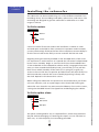
Positioning the subwoofer
Although it is difficult to localise very low frequency sounds, to get the best
from your system it is important to position your subwoofer carefully. You
will probably want to place the subwoofer where it is not to obtrusive, but
if possible follow these guidelines.
Position relative to other speakers
If there is a single subwoofer in your system, a recommended way of
positioning it is to connect it in a temporary location, and go around the
room listening for where the bass sounds most natural. Then position the
subwoofer in that location. If you have additional subwoofers you can
repeat this for the remaining subwoofers.
If the subwoofer is handling the bass for specific speakers in the system,
position it as close as possible to those speakers. This will give a more
impressive bass effect. For example if you have stereo subwoofers, which
are recommended for music reproduction, place them near to the left and
right speakers. This will ensure that the bass blends optimally between the
main speakers and the subwoofers, giving a good stereo image.
If you have a single mono or centre subwoofer, place it close to the centre
of the room at the front, ideally under the centre channel if you have one.
Face the front of the subwoofer towards the listening position. With
movies this makes effects more convincing. Do not place anything in front
of the subwoofer which could obstruct the air movement from the drive
units.
Mechanical interference
Subwoofers produce very high levels of bass, which may cause objects in a
room to rattle, and create boomy standing-wave resonances due to the
shape of the room. You can minimise these problems by positioning the
speakers carefully. If you have a Meridian Digital Surround Processor or a
test disc, use the sinewave sweep test to locate resonances and eliminate
them.
General recommendations
If possible you should locate the subwoofer so that the electronics on the
back of the speaker are not subjected to long term strong sunshine. The
rear panel should be cool when the unit is not in use.
14
SETTING UP THE
SUBWOOFER
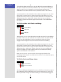
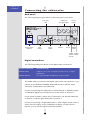
Connecting the subwoofer
Back panel
The following diagram gives details of the back panel connections:
*
Ê
«ÕÌÃ
>>Vi`Ê
>>}ÕiÊ«ÕÌÃ
Ü«>ÃÃÊ
vÌiÀ
8,Ê Ê *1/
*" "Ê *1/
/
,/
1-/Ê"7
*--Ê/,
*-
>Ê
VÌÀ
*
>ÃiÊ
ÃÜÌV
"1/*1/
*1/
Ã
" "
,/
,-/
, Ê
" *1/
*ÜiÀÊÃÜÌV
Ê
>`ÊvÕÃi
/
" "
"1/*1/
,iÃiÌ
}Ì>Ê
«ÕÌ
}Ì>Ê }Ì>Ê
V
>iÊ ÕÌ«ÕÌ
ÃiiVÌÀ
Digital connections
The following table gives details of the digital audio connections:
Use this connection
To connect to this
DIGITAL INPUT
A digital source, such as a digital sound processor, or digital
preamplifier.
DIGITAL OUTPUT
A second (slave) DSP loudspeaker, using an S5 lead.
The S/PDIF cable connected to the digital input carries two channels, so you
need to set the DIGITAL CHANNEL SELECTOR switch to indicate which
channel(s) are directed to the subwoofer.
If you are connecting the subwoofer to the Centre/Sub or Side/Sub output
of a Meridian digital surround processor, set the switch to position 2.
If your system includes a stereo pair of subwoofers, set the left subwoofer
to position 1 and the right subwoofer to position 2.
If you are connecting a single subwoofer to a stereo digital system with no
centre channel output, such as a Meridian CD player, set the switch to
position 1+2, to mix the signals from both channels.
15
SETTING UP THE
SUBWOOFER
The digital connections should be made with high-quality 75Ω screened
cable. Suitable cables are available from Meridian. We do not recommend
using analogue audio cables, which do not have adequate shielding or the
correct impedance, or cables intended for UHF applications, as these do not
provide adequate shielding in the 1–30MHz region.
Analogue connections
The following table gives details of the analogue audio connections:
Use this connection
To connect to this
PHONO INPUT MONO
The dedicated subwoofer output of a preamplifier or digital
surround controller, if it is the only subwoofer in the system, or
the left or right output of a preamplifier or digital surround
processor, if the subwoofer is used as one of a stereo pair.
PHONO INPUT LEFT/
RIGHT
The left and right outputs of a preamplifier or digital surround
processor, if it is the only subwoofer.
XLR BALANCED INPUT
MONO
The dedicated balanced subwoofer output of a preamplifier or
digital surround controller, if it is the only subwoofer in the
system, or the left or right XLR output of a preamplifier or
digital surround processor with balanced outputs, if the
subwoofer is one of a stereo pair.
XLR BALANCED INPUT
LEFT/RIGHT
The left and right XLR outputs of a preamplifier or digital
surround processor with balanced outputs, if it is the only
subwoofer.
If you are connecting a single subwoofer to a preamplifier or surround
processor with a dedicated subwoofer output, connect this to the
appropriate mono input on the subwoofer. Otherwise connect the left and
right outputs to the subwoofer left/right inputs, and the subwoofer will
mix the channels.
If you are connecting two subwoofers to a system, connect the left channel
output to the mono input of the left subwoofer and the right channel
output to the mono input of the right subwoofer.
The audio connections should be made with high quality audio phono
leads or XLR leads.
Communications connections
The following table gives details of the communications connections:
Use this connection
To connect to this
MERIDIAN COMMS
The COMMS connection on a Meridian control unit or
preamplifier, using a COMMS lead
16
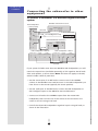
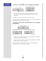
Connecting the subwoofer to other
equipment
To connect a subwoofer in a Meridian digital surround
system
iÀ`>Ê-ÕÀÀÕ`Ê*ÀViÃÃÀ
/
""1/*1/ "1/*1/Ê *1/
-*ÊÕ`ëi>iÀ
iÌÀiÊ>ÃÌiÀ®
/Ê *1/
Ó
£
SETTING UP THE
SUBWOOFER
"-
x££Ê-«>ÌV
ÊLÝ
-9Êi>`
-xÊi>`Ê`}Ì>ÊÕÕÃi`®
-xÊi>`
-7£ÈääÉ-7xxääÊ-ÕLÜviÀ
/ /
*1/ "1/*1/
"Ó
-xÊi>`
-*ÊÕ`ëi>iÀÊqÊ>Ê,
/Ê *1/
Ó
£
/Ê"1/*1/
É- É,
xÊi>`
/
""1/*1/ "1/*1/Ê *1/
-*ÊÕ`ëi>iÀÊqÊ>Ê
/Ê *1/
Ó
£
/
""1/*1/ "1/*1/Ê *1/
-xÊi>`
If your system includes more than two Meridian DSP loudspeakers you will
need a 511 S-patch box (available separately) to link together the S5 leads
from each speaker, as shown above. Note: This does not apply to the 861,
which includes a built-in patch box.
• Use the comms part of an M5 lead to connect one of the COMMS
sockets on the Meridian Surround Processor to the DSP loudspeaker you
have chosen as the master (typically the centre speaker).
• Use the audio part of the M5 lead to connect the DSP loudspeaker to
the C/S digital output on the Meridian Surround Processor.
• Connect an SY-lead to the COMMS output from the master DSP
loudspeaker, then connect one of the sockets on the SY lead to one
socket on the 511 using an S5 lead.
• Link all the other DSP loudspeakers together in pairs using S5 leads, as
shown in the illustration.
17
SETTING UP THE
SUBWOOFER
• Connect each pair of DSP loudspeakers to the appropriate digital output
on the Meridian Surround Processor, using an S5 lead. The other part of
the S5 lead is used to distribute the COMMS from the 511 to each pair of
DSP loudspeakers.
• Set the digital channel selection switch to position 2 on the subwoofer.
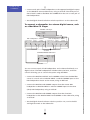
To connect a subwoofer to a stereo digital source, such
as a Meridian CD Player
iÀ`>Ê
Ê*>ÞiÀ
/
"- "1/*1/
xÊi>`
-*ÊÕ`ëi>iÀÊqÊ>Ê,
/Ê *1/
Ó
£
-*ÊÕ`ëi>iÀÊqÊ>Ê
/
""1/*1/ "1/*1/Ê *1/
/Ê *1/
Ó
£
/
""1/*1/ "1/*1/Ê *1/
-xÊi>`
-7£ÈääÉ-7xxääÊ-ÕLÜviÀ
/ /
*1/ "1/*1/
"£³Ó
-xÊi>`
You can connect a pair of DSP loudspeakers and a subwoofer directly to a
digital source. The DSP loudspeakers include volume, balance, and tone
controls allowing you to control the system using the MSR+.
• Connect the DIGITAL OUTPUT and a COMMS socket from the Meridian
source or control unit to DIGITAL INPUT 1 and the COMMS input on the
DSP loudspeaker chosen as the master, using an M5 lead.
• Connect the DIGITAL and COMMS outputs from the master DSP
loudspeaker to DIGITAL INPUT 1 and the COMMS input on the other
(slave) DSP loudspeaker, using an S5 lead.
• Connect the DIGITAL and COMMS outputs from the slave DSP
loudspeaker to the DIGITAL INPUT and COMMS on the subwoofer, using
an S5 lead.
• Set the digital channel selector switch to position 1+2, to mix the left
and right channels to the subwoofer.
18
SETTING UP THE
SUBWOOFER
To connect a subwoofer to an analogue preamplifier
-7£ÈääÉ-7xxääÊ-ÕLÜviÀ
>}ÕiÊ*Ài>«viÀ
8,Ê *1/-
*" "
"1/*1/
,
*" "
*1/-
• Connect the analogue outputs from the preamplifier or analogue
surround processor to the LEFT and RIGHT phono inputs of the
subwoofer.
The subwoofer mixes the channels to create a mono signal.
If your preamplifier provides balanced outputs, use the LEFT and RIGHT XLR
BALANCED inputs on the subwoofer instead.
To connect a stereo pair of subwoofers to an analogue
preamplifier
>}ÕiÊ*Ài>«viÀ
*" "
"1/*1/
,
-7£ÈääÉ-7xxääÊ-ÕLÜviÀ
8,Ê *1/-
-7£ÈääÉ-7xxääÊ-ÕLÜviÀ
*" "
*1/-
8,Ê *1/-
*" "
*1/-
• Connect the left analogue output from the preamplifier to the MONO
PHONO INPUT of the left subwoofer.
• Connect the right analogue output from the preamplifier to the MONO
PHONO INPUT of the right subwoofer.
If your preamplifier provides balanced outputs, use the MONO XLR
BALANCED input on each subwoofer instead.
19
SETTING UP THE
SUBWOOFER
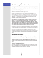
Adjusting the subwoofer
To set the adjustable low-pass filter
The subwoofer includes a low-pass filter which can be adjusted between
40Hz and 150Hz, or disabled using the DEFEAT switch.
1-/Ê"7
*--Ê/,
If you are connecting the subwoofer to a digital surround processor that
provides its own crossover, such as a Meridian digital surround processor,
set the low-pass filter switch to DEFEAT.
If you are connecting the subwoofer to an analogue preamplifier or
surround processor, set the low-pass filter to the middle of its range, and
then listen to a sweep tone from the processor if it provides one, or
alternatively from a test disc, and make sure the bass is smooth throughout
the range.
If there is a peak in the bass loudness, the subwoofer may be adding to the
bass from your main speakers, in which case reduce the low-pass filter
frequency.
Likewise, if there is a dip in the bass loudness, increase the low-pass filter
frequency.
To set the gain
The GAIN control allows you to adjust the loudness of the subwoofer to
suit the other components in your system.
For the best signal to noise ratio, adjust the level of the subwoofer using
the level control on the subwoofer. If you are using a Meridian Digital
Surround Processor, you can then use the processor’s calibration option to
fine-tune the subwoofer level if necessary.
If your surround processor or preamplifier does not include a Calibration
option, listen to familiar source materials and adjust the gain until the bass
sounds solid and deep, but not boomy or intrusive.
20
SETTING UP THE
SUBWOOFER
To set the phase
The PHASE switch allows you to invert the phase of the signal to the
subwoofer.
If your digital surround processor includes a Calibration option you can
adjust the phase in the surround processor, in which case set the switch to
the + position.
If the bass sounds hollow or phasey, and does not image correctly, change
the position of the PHASE switch. If in doubt, select the position that gives
the most bass.
21
SETTING UP THE
SUBWOOFER
22
Troubleshooting
This chapter provides suggested solutions to typical problems that
may occur when setting up the subwoofer.
If you are still not able to resolve a difficulty with the help of this
guide and the suggestions in the following pages, please contact your
Meridian dealer or Meridian Audio Ltd.
#$
2!$)/
$6$
&UNCTION
4OP-ENU
!58
$)3#
4!0%
46
#!",%
3!4
6#2
6#2
'!-%
/&&
0OWER
0AGE
!UDIO
0AGE
%NTER
3LOW
/PEN
-ENU
2ETURN
2EPEAT
3ETUP
2ECORD
"AND
!NGLE
23
3UBTITLE
$30
3TORE
#LEAR
0HASE
!"
/3$
$ISPLAY
-UTE
TROUBLESHOOTING
Troubleshooting
Unit goes silent when played hard
The subwoofer has a temperature sensing system on board, which prevents
overheating of the electronics. The sound will continue when the speaker
has cooled.
There is radio interference
The subwoofer is a digital audio and computing device which has been
designed to very high standards of electromagnetic compatibility.
If this equipment does cause or suffer from interference to/from radio or
television reception then the following measures should be tried:
• Reorient the receiving aerial (or antenna) or route the antenna cable of
the receiver as far as possible from the subwoofer and its cabling.
• Ensure that the receiver uses well-screened antenna cable.
• Relocate the receiver with respect to the subwoofer.
• Connect the receiver and this product to different AC outlets.
• If the problem persists contact your dealer.
Drive units move when the speaker is switched on or
off
This is normal as the speaker active electronics settle.
Subwoofer stays in standby
This indicates a problem with the Comms setup:
• Check the comms cabling; see Connecting the subwoofer to other
equipment, page 17.
• Reselect the source and increase or decrease the volume.
Subwoofer output sounds odd and lacking in bass
when connected to a Meridian digital processor
A digital audio connection carries two channels. Make sure that you are
picking up the right one. For example, if you have connected the
subwoofer to the Centre/Sub output of the processor, make sure that the
digital input switch is set to 2 to pick up the sub signal. If it is set to 1 you
will hear the signal intended for the centre channel.
If the speaker on a channel is configured as Small its signal will not contain
any bass, and a subwoofer set to pick up that channel will therefore not
output much of a signal. Check the subwoofer definitions in the
configuration and change as necessary.
24
TROUBLESHOOTING
Service and guarantee
Service
The Meridian components have been carefully designed to give years of
untroubled service. There are no user-serviceable parts inside the case, nor
do the units require any form of maintenance.
In the unlikely event that your subwoofer fails to function correctly,
it should be returned, in its original packaging, to your Meridian dealer.
In case of difficulty within the UK or USA please contact the appropriate
sales and service address shown on page iv.
In case of difficulty outside the UK or USA, contact the importing agent for
the territory. A list of Meridian agents abroad is available from Meridian
Audio.
No responsibility can be accepted for the subwoofer whilst in transit to the
factory or an agent, and customers are therefore advised to insure the unit.
When seeking service under guarantee, proof of the date of purchase will
be required.
Guarantee
Each subwoofer is guaranteed against defects in material and workmanship
for two years from the date of purchase.
The guarantee is void if the subwoofer has been subject to misuse,
accident, or negligence, or has been tampered with or modified in any way
without the written authorisation of Meridian Audio Limited.
Note: Connecting anything other than the correct network lead to the
COMMS sockets may cause damage to the subwoofer which will not be
covered by this guarantee. Attempted servicing by unauthorised people
may also invalidate this guarantee. Labour and carriage charges are not
covered unless by local agreement.
Outside the UK, local warranty liability is restricted to equipment
purchased within the territory. Our agents abroad are only under
contractual obligation to service under guarantee equipment sold through
them. They are entitled to make a non-refundable charge for any service
carried out on other equipment.
This guarantee does not limit your statutory rights within the United
Kingdom.
25
TROUBLESHOOTING
26
Index
A
accessories
analogue connections
M
8
16
Meridian Digital Music System
Meridian Digital Theatre™
B
balanced inputs
P
16
phase, setting
positioning
power amplifiers
C
cabinet
castors, fitting
COMMS connections
communications connections
components
connecting to other equipment
connections
analogue
COMMS
communications
digital
2
11
16
16
10
17
safety warnings
sample configurations
Meridian Digital Music System
Meridian Digital Theatre™
service
specification
SW1600
SW5500
spikes, fitting
with feet
SW1600
SW5500
16
16
16
15
15
2, 13
tightening the drive units
troubleshooting
12
unpacking
20
25
L
low-pass filter, setting
3
3
25
4
6
11
12
4
6
13
23
U
G
gain, setting
guarantee
ii
T
F
foot mouldings, fitting
21
14
2
S
D
digital connections
drive units
3
3
20
27
10
28