1
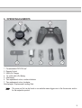
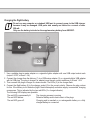
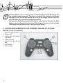
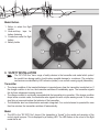
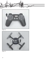
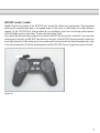
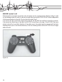
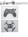
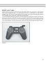
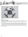
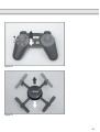
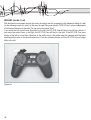
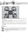
Operating instructions
88003RC (mode 2)
88004RC (mode 3)
RC EYE One
Page 3 – 34
These Operating Instructions accompany this product. They contain important information on
setting up and using the device. You should refer to these instructions, even if you are buying
this product for someone else.
Please retain these Operating Instructions for future use! A list of the contents can be found in
the Table of contents, with the corresponding page number, on page 3.
2
TABLE OF CONTENTS
1..Introduction................................................................................................................................................. 4
2..Intended use .............................................................................................................................................. 5
3..Delivery content.......................................................................................................................................... 5
4..Safety instructions...................................................................................................................................... 5
5..Product description..................................................................................................................................... 8
6..Operating elements.................................................................................................................................... 9
7..Start preparations..................................................................................................................................... 10
8..Operating elements of the transmitter and RC EYE ONE........................................................................ 12
9..Safety installation..................................................................................................................................... 14
10..Information for First Take-Off.................................................................................................................. 15
11..The first take-off ..................................................................................................................................... 28
12..Binding Function..................................................................................................................................... 30
13..Switch Transmitter Channel.................................................................................................................... 30
14..Maintenance, care and repair................................................................................................................. 31
15..Disposal.................................................................................................................................................. 32
16..Federal Communications Commission (FCC) DISCLAIMER................................................................. 33
17..Product support...................................................................................................................................... 34
18..Technical data......................................................................................................................................... 34
3
1. INTRODUCTION
Dear customer,
Thank you for making the excellent decision to purchase this RC Logger® product. You now have a highquality product with a name that represents outstanding products.
This product complies with the applicable National and European standards and regulations. We kindly
request the user to follow the operating instructions, to preserve this condition and to ensure safe operation!
These operating instructions relate to this product. They contain important notices on commissioning and
handling. Please take this into consideration when you pass the product on to third parties.
Please keep these instructions for further reference!
All company names and product designations contained herein are trademarks of the respective owners.
All rights reserved.
We wish you a great deal of enjoyment with your new RC Logger® product!
4
2. INTENDED USE
The model “RC EYE one” is a model helicopter solely designed for private use in the model making area
and the operating times associated with this. This system is not suitable for other types of use. Any use
other than the one described above damages the device. Moreover, this involves dangers such as short
circuit, fire, electric shock, etc. Observe the safety information under all circumstances! The product must
not become damp or wet. This product is not a toy and not suitable for children under 14 years of age.
For safety and approval purposes (CE), you must not rebuild and/or modify this product. If you use the
product for purposes other than those described above, the product may be damaged. In addition, improper
use can cause hazards such as short circuiting, fire, electric shock etc. Read the instructions carefully and
keep them. Make this product available to third parties only together with its operating instructions.
3. DELIVERY CONTENT
>>
>>
>>
>>
>>
>>
>>
>>
1 x RC EYE One
1 x 7.4 V 350 mAh LiPo Battery
1 x USB LiPo Charger
4 x Replacement Rotor (2 x black, 2 x red)
2 x Replacement Landing Skid
1 x Remote control
2 x AAA Battery
Operating instructions
4. SAFETY INSTRUCTIONS
Read the operating instructions carefully and especially observe the safety information.
If you do not follow the safety instructions and information on proper handling in this
manual, we assume no liability for any resulting personal injury or damage to property.
Such cases will invalidate the warranty/guarantee.
Persons / Product
>> The device is not a toy. Keep it out of the reach of children and pets.
>> Do not leave packaging material lying around carelessly. These may become dangerous playing
material for children.
>> The product must not become damp or wet. As delicate control electronics are used in the “RC EYE
one” which are also sensitive to temperature fluctuations and are optimised for a particular temperature
range, operation below 0°C is to be avoided.
>> Do not place the product under any mechanical stress.
>> If it is no longer possible to operate the product safely, take it out of operation and protect it from any
accidental use. Safe operation can no longer be guaranteed if the product:
-- is visibly damaged,
-- is no longer working properly,
5
-- has been stored for extended periods in poor ambient conditions or
-- has been subjected to any serious transport-related stresses.
>> Handle the product carefully. Jolts, impacts or a fall even from a low height can damage the product.
Before commissioning
>> Make sure that no other models are operated on the same channel (transmitter frequency) within the
range of the remote control. This applies for all products operated at 915 MHz (e.g. weather stations,
radio headphones, etc.). Otherwise, you will lose control of the remote-controlled models! Always
use different channels if you wish to operate two or several models in direct proximity of each other
simultaneously.
>> Regularly check the functional reliability of your model and the remote control system. Watch out for any
visible damage such as defective plug connections or damaged cables.
>> All moving parts of the model must run smoothly but should not have any play in their bearings.
>> Check before each operation the correct and secure position of the rotors.
>> The flight battery required for operation must be charged according to these operating instructions.
>> Ensure sufficient residual capacity (battery tester) of the batteries inserted in the transmitter. If the
batteries are empty, always replace the complete set, never individual cells only.
>> Always switch on the transmitter first. Please ensure that when you turn on the transmitter the throttle
control is set to the lowest setting (motors off)! Then the flight battery of the model may be connected.
Otherwise, unexpected reactions of the model may occur and the rotors might run unintentionally!
>> When the rotors are running, make sure that neither objects nor body parts are in the rotating and
suction area of the rotors.
During Operation
>> Do not take any risks when operating the model! Your own safety and that of your environment is solely
down to you being responsible when dealing with the model.
>> Improper operation may cause serious injury and property damage! Therefore make sure to keep a
sufficiently safe distance to persons, animals or objects during operation.
>> Select an appropriate location for the operation of your model.
>> Fly your model only if your ability to respond is unrestricted. The influence of tiredness, alcohol or
medication can cause incorrect responses.
>> Do not direct your model towards spectators or towards yourself.
>> Motor, electronics and flight battery may heat up during operation of the model. For this reason, wait for
5 to 10 minutes before recharging or replacing the flight battery.
>> Never switch off the remote control (transmitter) while the model is in use. After landing, always
disconnect the flight battery first. Only then may the remote control be switched off.
>> In case of a defect or a malfunction, remove the problem before using the model again.
>> Never expose your model or the remote control to direct sunlight or excessive heat for an extended
period of time.
>> In the case of a severe crash (e.g. from a high altitude). the electric gyro sensors can be damaged and/
or misadjusted. Therefore, full functionality must be tested before flying again without fail!
6
>> In the event of a crash, the throttle should be immediately reduced to zero. Rotating rotors may be
damaged if they come into contact with obstacles e.g. overcharging. Before flying again, these should
be checked for possible tears or breakages!
>> To avoid damage to the “RC EYE One” helicopter through crashing due to low voltage of the rechargeable
battery through total discharge, we recommend that you respect the low voltage light signals without fail.
Batteries
>> Correct polarity must be observed while inserting the batteries.
>> Batteries should be removed from the device if it is not used for a long period of time to avoid damage
through leaking. Leaking or damaged batteries might cause acid burns when in contact with skin,
therefore use suitable protective gloves to handle corrupted batteries.
>> Batteries must be kept out of reach of children. Do not leave the battery lying around, as there is risk,
that children or pets swallow it.
>> All the batteries should be replaced at the same time. Mixing old and new batteries in the device can lead
to battery leakage and device damage.
>> Batteries must not be dismantled, short-circuited or thrown into fire. Never recharge non-rechargeable
batteries. There is a risk of explosion!
>> Never mix batteries and rechargeable batteries!
LiPo batteries
>>
>>
>>
>>
After the flight, the LiPo flight battery must be disconnected from the electronics system
of the “RC EYE One”. Do not leave the LiPo flight battery connected to the helicopter
electronic system when you do not use it (e.g. during transport or storage). Otherwise
the LiPo flight battery may be fully discharged. This would destroy it and render it
unusable! There is also a danger of malfunction due to interferences. The rotors could
start up inadvertently and cause damage or injury.
There is the risk of fire or explosion by the rechargeable battery. Rechargeable LiPo
batteries in particular are very susceptible to moisture due to the chemicals they
contain! Do not expose the charger or LiPo flight battery to high/low temperatures
or to direct solar radiation. When handling LiPo batteries, observe the special safety
information of the battery manufacturer!
Never charge the LiPo flight battery immediately after use. Always leave the LiPo flight battery to cool
off first (at least 5-10 minutes).
Due to the special circuit at the battery plug, the flight battery can be charged with conventional LiPo
chargers. Therefore, use the included LiPo charger only to charge the flight battery.
Only charge intact and undamaged batteries. If the external insulation of the rechargeable battery is
damaged or if the rechargeable battery is deformed or bloated, it must not be charged. In this case, there
is immediate danger of fire and explosion!
Never damage the exterior of a LiPo flight battery. Never cut the covering foil. Never stab any LiPo flight
batteries with pointed objects. There is a risk of fire and explosion!
7
>> Remove the LiPo flight battery that is to be charged from the model and place it on a fire-proof support
(e.g. a plate). Keep a distance to flammable objects (use USB extension cable if required).
>> As the charger and the rechargeable LiPo flight battery both heat up during the charging procedure, it is
necessary to ensure sufficient ventilation. Never cover the charger or the LiPo flight battery! Of course,
this also applies for all other chargers and rechargeable batteries.
>> Never leave LiPo batteries unattended while charging them.
>> Disconnect the LiPo flight battery from the charger when it is fully charged.
>> Chargers may only be operated in dry rooms. The charger and the LiPo flight battery must not get
damp or wet.
Miscellaneous
>> Consult an expert when in doubt about operation, safety or connection of the device.
>> Maintenance, modifications and repairs are to be performed exclusively by an expert or at a qualified
shop.
>> If you have questions which remain unanswered by these operating instructions, contact our technical
support service or other technical personnel.
5. PRODUCT DESCRIPTION
The electric helicopter model “RC EYE one” is a pre-assembled helicopter-like flight model with four rotors.
In the professional field, such flight devices are already used for the most diverse of tasks. The latest micro
processor controlled electronics with position control and acceleration sensor stabilise the “RC EYE one”.
High-quality direct current engines in connection with a specially developed control permit a long, powerful
flight operation. The new control and electronic self-stabilisation lead to great flight properties. Different
flying programmes ensure that both beginners and experts will be able to have their fun.
The flight model can be operated both in inner rooms and outdoors on windstill days. The in-built electronic
controls can balance out small undesired changes to the flight altitude, but cannot remove them completely.
As the “RC EYE one” weighs less than 100 grams, it reacts sensitively to wind or draughts.
Three different flight models (starters, sports, expert) may be selected. The model therefore is designed for
beginners as well as experienced model helicopter pilots. The model grows with your flight skills.
The remote control transmitter may be programmed to five different transmitter channels. Five pilots can fly
five “RC EYE one” at the same place.
8
6. OPERATING ELEMENTS
1. Pre-assembled “RC EYE one”
2. Remote Control
3. USB LiPo Charger
4. 7.4 V 350 mAh LiPo Battery
5. AAA Battery
6. Two replacement rotors, counter-clockwise
7. Two replacement rotors, clockwise
Not displayed: Replacement Landing Skid
The spare part list can be found on our website www.rclogger.com in the Accessories section
for the respective product.
9
7. START PREPARATIONS
Inserting batteries in the transmitter
1. Remove the battery
compartment lid (1) of the
transmitter. You need to
push the lever (2) down
slightly for this.
2. Insert two micro/AAA size
batteries with the correct
polarity (3). Observe the
corresponding icons in the
battery compartment. Insert
the battery compartment lid
again.
Operation of the transmitter with rechargeable batteries is not recommended because of
the lower cell voltage (battery = 1.5 V, rechargeable battery = 1.2 V) and the self-discharge
of rechargeable batteries. Quick feedback of the transmitter on low charge status of the
transmitter power supply would result.
Since the transmitter requires very little power, batteries will keep much longer. We recommend
the use of high-quality alkaline batteries.
10
Charging the flight battery
Do not use any computer or notebook USB port to connect power to the USB charger
because it may be damaged. USB ports also usually are limited to a current of max.
500 mA.
Only use the battery included or the supplementary battery from 89029RC.
1. Use a suitable plug-in mains adapter or a cigarette lighter adapter with one USB output socket each
(output 5 V/DC, at least 1.5 A).
2. Connect the charger from the delivery (1) to a USB mains adapter (2) or a cigarette lights USB adapter
with its USB plug. The plug-in charger (or adapter) must have a current resilience of at least 1.5 A!
3. Then connect the plug-in charger to a mains socket. The LEDs (3) in the charger flash.
4. Connect the flight battery (4) to the charger socket (5) in the correct polarity. Observe the plug contour
for this. If the battery is not defective (high-Ohmic/interrupted) and mains supply is warranted, charging
commences. This is indicated by the two red LEDs (3 = charge indicator).
The following LED displays are possible:
The red LED is permanently lit:
The red LED flashes:
The red LED goes off:
The charging process is running
Defective battery and/or bad contact of the plugs
Charging end is reached or no rechargeable battery or a fully
charged battery is connected
11
Individual battery cells of a battery pack are usually different. The USB charger has
two separate chargers integrated. Therefore, it is possible that a battery cell is already
charged (LED off) and the other battery cell is still being charged (LED on). Wait until
both LEDs have gone out before unplugging the battery.
The plug at the flight battery must be connected in a special manner. Therefore, the flight
battery cannot be charged with conventional LiPo chargers. Therefore, use the included
USB charger from the delivery only to charge the flight battery.
8. OPERATING ELEMENTS OF THE TRANSMITTER AND RC EYE ONE
88003RC (mode 2) Transmitter
1. Button for channel selection
2. Button on/off
3. Control stick left (throttle
and rudder)
4. Rudder trimming
5. Control stick right (roll and
nick)
6. Nick trimming
7. Roll trimming
12
88004RC (mode 3) Transmitter
1. Button on/off
2. Button for channel selection
3. Control stick right (throttle
and rudder)
4. Roll trimming
5. Control stick left (roll and
nick)
6. Nick trimming
3
5
6
4
2
1
Model Top
1. Rotors front (red rotors)
2. Rotors rear (black rotors)
3. LED for status display
13
Model Bottom
1. Button to select the flight
modes
2. Hook-and-loop tape for
battery fastening
3. Connection socket for flight
battery
4. Battery holder
9. SAFETY INSTALLATION
The “RC EYE One” has a range of safety devices in the transmitter and model which protect
the model from damage and/or should reduce possible damage to a minimum. The protection
mechanisms are identified by LED indicators (model) or an acoustic warning signal (transmitter).
Transmitter
>> The charge condition of the inserted batteries is inspected every time the transmitter is switched on. If
the charge condition is too low, the transmitter switches off immediately again. The transmitter signals
this by three subsequent warning sounds.
>> The charge condition is continually inspected while the transmitter is in operation. If the charge condition
drops below a certain value, the transmitter also signals this with a triple warning sound. In this case,
stop flying at once and replace the batteries of the transmitter.
>> The transmitter also has a deactivation automatic integrated. If no control element is operated for more
than five minutes, the transmitter switches off automatically.
Model
>> The LED in the “RC EYE One” shows if the transmitter is “bound” to the model and reception of the
control signal is proper. This is displayed by a flashing LED. The LED flashes in the colour of the flight
mode that is set.
14
>> If there is any interference with reception, the LED is continually lit in the colour of the set flight mode.
If reception interferences are permanently present in flight operation, the motors are switched off after
approx. five seconds (emergency landing initiated).
>> Short-term reception interferences are ignored by the “RC EYE One” by the last control signals of the
transmitter retaining the last flight condition in connection with the integrated sensors.
>> The “RC EYE One” constantly monitors the voltage of the connected batteries. If it falls below a critical
level over a particular period of time, this will be indicated by an orange flashing LEDs.
>> If the voltage undercut is permanently below a certain value, the LED is lit permanently orange. In this
case, an emergency landing is initiated after a short period and the motors and LED are deactivated.
The LED in the “RC EYE One” flashes either green (beginners), orange (sports) or red (expert),
depending on the flight mode set. At short-term undercut of the undervoltage display, the LED
flashes green/orange in beginner’s mode.
In sports mode, the LED flashes irregularly at undervoltage recognition. If the voltage undercut
is present permanently, the LED is lit orange permanently independently of the flight mode set.
If the “RC EYE One” is connected to a non-fully charged battery, this can also lead to
undervoltage detection and the motors do not start. In this case, fully charge the flight battery
first of all and then try the take-off once again.
As another safety measure, the motors are switched off once one or several rotors are blocked. If this is
the case, the LED in the model flashes red at a quick rhythm. To reset this condition in the electronics,
disconnect the flight battery and connect it again.
10.INFORMATION FOR FIRST TAKE-OFF
For a simpler and consistent explanation of steering, classic terminology is used here as well.
This comes from flight language and is widely used.
Direction descriptions are always to be interpreted from the perspective of a “virtual” pilot in
the model. The two red rotors are considered direction indicators. They mean “front”. The
explanations are all based on configuration of the remote control to mode II.
88003RC (mode 2) hover Flight
Hovering denotes a flight status in which the “RC EYE One” neither rises nor falls so that the upwards
directed uplift force is equal to the downwards directed weight. This is achieved about at the central throttle
position. Push the throttle lever (figure 1) forward to increase the motor speed and lift up the RC EYE One.
Pulling the throttle lever back causes the RC EYE One to drop. Pulling the throttle lever back all the way
shuts off the engines.
During flight close above the ground and during take-off, turbulence and air flow can be
experienced which may affect the “RC EYE One”. A quicker response to the controlling motions
and slight swerving of the “RC EYE One” forwards, backwards or to the side may result from
this. This so-called ground effect is no longer present starting at a fight height of about 50 cm.
15
Figure 1a
Figure 1b
16
88003RC (mode 2) rudder
Rudder denotes the rotation of the “RC EYE One” around the rudder axis (vertical axis). This movement
either occurs unintentionally due to the speed torque of the rotors or intentionally as a flight direction
change. For the “RC EYE One”, this movement is not controlled by a tail rotor, but through speed variation
of the individual rotors to each other. The two red rotors show “front”.
If you move the left control lever (figure 2a) to the left, the RC EYE One will turn to the left. If you move the
control lever to the right, the RC EYE One will turn to the right. If the RC EYE One turns slowly to the left in
hover flight (direction of the white arrow), the model must be trimmed with the black trimming button (also
in the counter-direction). Push the trimming button until the RC EYE One no longer turns away to the left.
Figure 2a
17
Figure 2b
88003RC (mode 2) nick
Nick denotes the movement around the cross axis which can be compared to the nodding of a head.
Through this, the “RC EYE One” gains flight speed forwards or backwards or decelerates. The two red
rotors show “front”.
If you move the right control lever (figure 3a) to the front, the RC EYE One will float forwards as a whole.
If you move the control lever to the rear, the RC EYE One will float backwards. If the RC EYE One turns
slowly to the rear in hover flight (direction of the white arrow), the model must be trimmed with the black
trimming button (also in the counter-direction). Push the trimming button until the RC EYE One no longer
turns away to the rear.
18
Figure 3a
Figure 3b
19
88003RC (mode 2) roll
Roll denotes the movement around the centre line which can be compared to the sideways rolling of a ball
(or the sideways crawl of a crab). In this way, through lifting one side the “RC EYE One” moves independent
of its forward direction to the side. The two red rotors show “front”.
If you move the right control lever (figure 4a) to the left, the RC EYE One will float to the left as a whole.
If you move the control lever to the right, the RC EYE One will float to the right. If the RC EYE One turns
slowly to the left in hover flight (direction of the white arrow), the model must be trimmed with the black
trimming button (also in the counter-direction). Push the trimming button until the RC EYE One no longer
drifts to the left.
Figure 4a
20
Figure 4b
88004RC (mode 3) hover Flight
Hovering denotes a flight status in which the “RC EYE One” neither rises nor falls so that the upwards
directed uplift force is equal to the downwards directed weight. This is achieved about at the central throttle
position. Push the throttle lever (figure 5a) forward to increase the motor speed and lift up the RC EYE One.
Pulling the throttle lever back causes the RC EYE One to drop. Pulling the throttle lever back all the way
shuts off the engines.
During flight close above the ground and during take-off, turbulence and air flow can be
experienced which may affect the “RC EYE One”. A quicker response to the controlling motions
and slight swerving of the “RC EYE One” forwards, backwards or to the side may result from
this. This so-called ground effect is no longer present starting at a flight height of about 50 cm.
21
Figure 5a
Figure 5b
22
88004RC (mode 3) rudder
Rudder denotes the rotation of the “RC EYE One” around the rudder axis (vertical axis). This movement
either occurs unintentionally due to the speed torque of the rotors or intentionally as a flight direction
change. For the “RC EYE One”, this movement is not controlled by a tail rotor, but through speed variation
of the individual rotors to each other. The two red rotors show “front”.
If you move the right control lever (figure 6a) to the left, the RC EYE One will turn to the left. If you move the
control lever to the right, the RC EYE One will turn to the right. If the RC EYE One turns slowly to the left in
hover flight (direction of the white arrow), the model must be trimmed with the black trimming button (also
in the counter-direction). Push the trimming button until the RC EYE One no longer turns away to the left.
Figure 6a
23
Figure 6b
88004RC (mode 3) nick
Nick denotes the movement around the cross axis which can be compared to the nodding of a head.
Through this, the “RC EYE One” gains flight speed forwards or backwards or decelerates. The two red
rotors show “front”.
If you move the left control lever (figure 7a) to the front, the RC EYE One will float forwards as a whole.
If you move the control lever to the rear, the RC EYE One will float backwards. If the RC EYE One turns
slowly to the rear in hover flight (direction of the white arrow), the model must be trimmed with the black
trimming button (also in the counter-direction). Push the trimming button until the RC EYE One no longer
turns away to the rear.
24
Figure 7a
Figure 7b
25
88004RC (mode 3) roll
Roll denotes the movement around the centre line which can be compared to the sideways rolling of a ball
(or the sideways crawl of a crab). In this way, through lifting one side the “RC EYE One” moves independent
of its forward direction to the side. The two red rotors show “front”.
If you move the left control lever (figure 8a) to the left, the RC EYE One will float to the left as a whole. If
you move the control lever to the right, the RC EYE One will float to the right. If the RC EYE One turns
slowly to the left in hover flight (direction of the white arrow), the model must be trimmed with the black
trimming button (also in the counter-direction). Push the trimming button until the RC EYE One no longer
drifts to the left.
Figure 8a
26
Figure 8b
Flight Mode
The “RC EYE One” permits you to choose between three different flight modes depending on your
experience. The button for this is at the bottom of the RC EYE One.
>> LED flashes green = beginner’s mode = strictly limited control commands
>> LED flashes orange = sports mode = slightly limited control commands
27
>> LED flashes red = expert mode = no limitation to control commands
In beginner mode, the control commands are limited to permit you learning how to fly the “RC EYE One”
very quickly and easily. This flight mode is recommended for pilots who have no or only very little flight
experience with helicopters or QuadroCopters yet. The beginner’s mode is the basic configuration after
each battery change.
The Sports mode is recommended to pilots who have already collected some experience with other
helicopter or QuadroCopter models. In this mode, the model is much more agile in its control conduct than
in beginner’s mode.
No control signals are limited in expert mode. The stabilisation sensors are clearly reduced in its effect. The
“RC EYE One” flies like a conventional helicopter or QuadroCopter in this mode. The control properties
are accordingly agile in this. This mode is recommended only to pilots who have already collected a lot of
experience with controlling helicopter or QuadroCopter models.
General Handling
A “RC EYE One” is essentially equipped with the handling of a normal helicopter. The differences, however,
are in the detail. For helicopters, the torque balance is stabilised by special gyros (in the rudder function).
For this, there are two different systems: “Normal gyros” or gyros with the “heading lock” function.
Normal gyros stabilise (cushion) the tail rotor against tipping motions which are caused by the pilots (driving
speed and/or nick changes and/or external influences (e.g. side wind). A gyro with “heading lock” function
has a holding action against these tipping motions.
Both systems respond after a control command – e.g. ”rudder to the left” and subsequent neutral positioning
with the immediate stopping of the tipping motion.
In your “RC EYE One”, unlike in standard helicopters, there are six gyros installed for the rudder, nick and
roll functions. The installed gyros are – in comparison with standard gyros – neither to be described as
normal gyros nor with “heading lock” function.
The gyros in the “RC EYE One” are linked together so that after the end of a control command the “RC EYE
One” always attempts to reach neutral position (hovering flight). Of course, how well this works depends on
the space available, the flight speed and/or the prevailing flight condition, the trim values of the “RC EYE
One” and external flight conditions e.g. wind.
This control logic is deactivated in expert mode. The position and flight control of the “RC EYE One”
corresponds to the last control command and is not neutralised.
11.THE FIRST TAKE-OFF
The operation and handling of remote controlled flight models must be learned! If you
have never steered such a model, start especially carefully and get used to the reactions
of the model to the remote control commands first. Do be patient! Use the information
from chapter INFORMATION FOR FIRST TAKE-OFF as reference.
Do not take any risks when operating the product! Your own safety and that of your
environment depends completely on your responsible use of the model.
28
1. Switch off the remote control transmitter by pushing the on/off button. The transmitter confirms this with
a double sound.
2. Put the throttle lever all the way back (engines out).
3. Resets the trims at the transmitter to “0”. For this, push the two associated trim buttons for rudder, nick
and roll (also see the figure in OPERATING ELEMENTS OF THE TRANSMITTER AND RC EYE ONE,
items 4, 6 and 7 of 88003RC (mode 2) Transmitter / items 4 and 6 of 88004RC (mode 3) Transmitter) in
sequence until neutralisation of the trimming is confirmed with a double sound signal.
4. Then connect the flight battery. For this, push the battery plug into the socket of the “RC EYE One” in the
correct polarity (also see he figure in OPERATING ELEMENTS OF THE TRANSMITTER AND RC EYE
ONE, Model Bottom, item 3; observe plug contours). The LED in the model starts flashing green after a
short period at a correct reception signal (starter mode).
5. Place the flight battery into the intended holder of the “RC EYE One” and secure it with hook-and-loop
tape (also see he figure in OPERATING ELEMENTS OF THE TRANSMITTER AND RC EYE ONE,
Model Bottom, items 2 and 4).
6. Push the setting bottom of the flight mode (figure 6, item 1) to select the desired mode.
-- LED flashes green = beginner’s mode (basic configuration after each battery change)
-- LED flashes orange = sports mode
-- LED flashes red = expert mode
7. Place the model on a level surface as smooth as possible (e.g. stone floor). A carpet is less suitable
because the landing legs may bet caught in the carpet easily.
8. Start the engines by carefully pushing the throttle lever forwards. Ideally, now slowly increase the speed
of the rotors (the throttle) of the “RC EYE One” until you can see a slight increase of altitude. Test the
roll and nick directions just before the “RC EYE One” starts to hover to ensure that the transmitter is
correctly set. Generally avoid any fast and big controlling motions. Also watch closely to see whether
and in which direction the “RC EYE One” moves. By using trimming on the remote control, you can
prevent undesired movements.
Important! Never take off with a badly trimmed flight device.
9. Then increase the throttle until the “RC EYE One” is at least 50 cm above the ground. At this height, you
have passed the so-called ground effect and the “RC EYE One” is more stable in its flight position and
can be controlled more easily. Carefully try to correct a gentle drift with the trim levers for rudder, nick
or roll. Once the “RC EYE One” is high enough in the sky, decrease the throttle until the “RC EYE One”
hovers. Also observe the notes in chapter INFORMATION FOR FIRST TAKE-OFF.
10.Now you have managed the critical part and can familiarise yourself with the “RC EYE One” by slow and
careful throttle controlling motions.
29
11.To land the “RC EYE One” again, decrease the throttle slightly until the “RC EYE One” gravitates to the
ground. A somewhat solid touchdown on the ground is no problem and should not be corrected with
jerky throttle movements. Try to touch down where possible in vertical position (“helicopter landing”).
Avoid landing with high horizontal speeds (“airplane landing”).
12.After landing, turn off the motors (pull back the throttle lever).
13.Practice this starting procedure a few times to get a feel for the “RC EYE One”. Once you are reasonably
sure, you can begin to steer the flight direction with rudder, nick and roll. Always steer slowly and
carefully and practice the processes a little before trying a new flight manoeuvre. The first flights should
not last longer than 30 to 60 seconds each.
14.When you have familiarised yourself a little with the model’s flight properties, you may perform additional
exercises. Start with simple flight manoeuvres like a flying a meter forwards/back (nod function). Then
practice hovering to the left/right (roll function). When you have the practice you need, start flying circles
and figure eights.
15.If you want to terminate flying, the engine must be switched off after landing. Then disconnect the battery
from the model. Only then must the transmitter be turned off. With the transmitter on, a single signal
sound will be emitted.
12.BINDING FUNCTION
The remote control transmitter and the model are coupled with a special encrypted transmitter signal. This is
referred to as “binding” of the two components that warranty widely interference-free operation. Transmitter
and model are bound ex works already. Outer influences (e.g. strong interference emission) may cause
loss of binding. In this case the “RC EYE One” would no longer react to the transmitter signal (LED in the
model is permanently lit).
To bind your transmitter to your model again, proceed as follows:
1. Connect the battery to the “RC EYE One”.
2. Push the button for flight mode selection for more than three seconds. The LED in the model now flashes
red/green alternately.
3. Push the on/off button for more than three seconds with the transmitter switched off. The transmitter
tarts beeping rhythmically.
4. The transmitter and model scan for each other and reconcile their data. After successful binding, the
LED in the model flashes in the last flight mode selected. The “RC EYE One” is ready to start again.
13.SWITCH TRANSMITTER CHANNEL
The transmitter of the “RC EYE One” may be programmed to five different transmitter channels. This
permits concurrent operation of up to five transmitters and “RC EYE One”.
You may also need to select another transmitter channel if you experience inference from other devices with
915 MHz-technology on the channel that is set (e.g. weather stations, radio headphones, etc.). Proceed as
follows for programming another transmitter channel:
30
1. Switch off the transmitter.
2. Push the button for channel selection for more than three seconds. A sound signal is emitted. The
number of sound signals indicates the transmitter channel number. A sound signal means transmitter
channel 1, two sounds signals mean transmitter channel 2, etc.
3. Now release the button. Then push the button repeatedly until the desired transmitter channel (e.g. 3
sound signals = transmitter channel 3) is set.
4. Confirm the new transmitter channel by pushing the on/off button. The programming is confirmed by a
single sound signal.
5. Now bind the transmitter and model as described in chapter BINDING FUNCTION.
14.MAINTENANCE, CARE AND REPAIR
Regular Cleaning
The ““RC EYE One”” is a very simple but nonetheless well-designed flying device. There are no mechanical
parts that need to be lubricated or require special maintenance. However, after each flight operation you
should clean the ““RC EYE One”” of possible dirt (wool strings, dust, etc.).
For cleaning, use a dry or slightly damp cloth and avoid contact between water and the electronics,
rechargeable battery and motors.
Do not fly without covering the electronics. Please ensure that no moisture enters the inner central piece.
Never fly when it is raining!
Replacing the Rotors
Attention!
Observe the rotating direction of the respective motor and the choice of the
corresponding rotor without fail. If these are incorrectly chosen, the model will not be
able to fly and will act in an erratic way when next started! Loss of guarantee/warranty!
The rotating direction is marked on the rotors (“L” or “R”). The mark “L” or “R” points
up.
The rotors marked “L” must be installed on the motors that turn leftwards (counter
clockwise).
The rotors marked “R” must be installed on the motors that turn rightwards (clockwise).
If a rotor is damaged in a crash or other action, replace it immediately. This also applies if there are any
fine tears or grazing in the rotor. Due to the high speed, material parts could come loose if the rotors are
damaged and this could lead to damage to or endangerment of the environment.
1. To replace a rotor, pull the damaged rotor from the motor shaft and replace it with a new one. The
rotors must not be pushed completely onto the motor shaft. Keep about 0.5 mm distance from the
motor housing.
31
L
R
R
L
2. For reference, put the “RC EYE One” onto your work surface with the model LED (see arrow) pointing
to the front right.
3. The front motors (motor 1 and 2) are at the “front” for this model and must have red rotors. Motor 1 turns
counter clockwise, motor 2 turns clockwise.
4. The rear motors (motor 3 and 4) must have black rotors. Motor 3 turns clockwise, motor 4 turns counter
clockwise.
5. Do not bend the motor shafts. Bent motor shafts (e.g. from crashes) influence the flight properties
negatively due to he vibration that results and the irritation to the sensors. Motors with bent motor shaft
must be replaced.
15.DISPOSAL
General
32
In order to preserve, protect and improve the quality of environment, protect human health and
utilise natural resources prudently and rationally, the user should return unserviceable product
to relevant facilities in accordance with statutory regulations.
The crossed-out wheeled bin indicates the product needs to be disposed separately and not
as municipal waste.
Batteries / rechargeable batteries
The user is legally obliged (battery regulation) to return used batteries and rechargeable
batteries. Disposing used batteries in the household waste is prohibited! Batteries/
rechargeable batteries containing hazardous substances are marked with the crossed-out
wheeled bin. The symbol indicates that the product is forbidden to be disposed via the domestic
refuse. The chemical symbols for the respective hazardous substances are Cd = Cadmium,
Hg = Mercury, Pb = Lead.
You can return used batteries/ rechargeable batteries free of charge to any collecting point of your
local authority, our stores or where batteries/ rechargeable batteries are sold.
Consequently you comply with your legal obligations and contribute to environmental protection!
16.FEDERAL COMMUNICATIONS COMMISSION (FCC) DISCLAIMER
FCC ID:
FCC ID:
OMO-M-17 Remote control (MC-120-RC)
OMO-M-18 RC EYE One (MC-120)
RF Exposure mobile:
The internal / external antennas used for this mobile transmitter must provide a separation distance of at
least 20 cm (8 inches) from all persons and must not be co-located or operating in conjunction with any
other antenna or transmitter.”
Statement according to FCC part 15.19:
This device complies with Part 15 of the FCC Rules. Operation is subject to the following two conditions:
>> this device may not cause harmful interference, and
>> this device must accept any interference received, including interference that may cause undesired operation.
Statement according to FCC part 15.21:
Modifications not expressly approved by this company could void the user’s authority to operate the equipment.
Statement according to FCC part 15.105:
This equipment has been tested and found to comply with the limits for a Class B digital device, pursuant
to Part 15 of the FCC Rules. These limits are designed to provide reasonable protection against harmful
interference in a residential installation. This equipment generates, uses and can radiate radio frequency
energy and, if not installed and used in accordance with the instructions, may cause harmful interference
to radio communications.
However, there is no guarantee that interference will not occur in a particular installation. If this equipment
does cause harmful interference to radio or television reception, which can be determined by turning the
equipment off and on, the user is encouraged to try to correct the interference by one or more of the
following measures:
33
>>
>>
>>
>>
Reorient or relocate the receiving antenna.
Increase the separation between the equipment and receiver.
Connect the equipment into an outlet on a circuit different from that to which the receiver is connected.
Consult the dealer or an experienced radio/TV technician for help.
The compliance statement for this product is available at “www.rclogger.com”.
17.PRODUCT SUPPORT
Visit “http://www.rclogger.com/index.php/contact-us” or call +852 2559 2662 for product support.
18.TECHNICAL DATA
Transmitter
Transmission frequency:
Number of transmitter channels:
Transmitter range:
Supply voltage:
Dimensions (W x H x D):
Weight:
915 MHz
5
max. 40 m (free field)
3 V/DC (2 type micro/AAA batteries)
150 x 100 x 70 mm
130 g
RC EYE One
Diameter without rotors:
Total height:
Rotor diameter:
Take-off weight:
Rechargeable battery:
Admissible flight operation:
Operating conditions:
Admissible temperature range:
Admissible humidity:
120 mm
47 mm
64 mm
approx. 80 g
7.4 V LiPo
Inner and outer area
No to light wind
0 to +40 °C
max. 75% rel. humidity, non-condensing
Charger
Supply voltage:
Required input current:
Charging current:
34
5 V/DC
min. 1.5 A
500 mA per charging channel
35
Legal notice
These operating instructions are published by CEI Conrad Electronic International (HK) Limited,
28th Floor & 2903-9, Pacific Plaza, 418 Des Voeux Road West, Hong Kong.
All rights including translation reserved. Reproduction by any method, e.g. photocopy, microfilming, or the capture in
electronic data processing systems require the prior written approval by the editor. Reprinting, also in part, is prohibited.
The operating instructions reflect the current technical specifications at time of print. We reserve the right to change the
technical or physical specifications.
© 2012 by CEI Conrad Electronic International (HK) Limited
V3_1112-HL
36