1
Programming Manual
PC6O1O Software Version 2.O
Introduction
Using PC6010 Manuals
There are 3 main manuals for PC6010 installers:
This manual (Programming Manual) contains a description of
all the PC6010 v1.0 programming sections. Use this manual
when you want to know what a programming section is for,
and what kind of data to enter in the section. See the “Main
Programming Sections” section on page 2, for an overview of
PC6010 programming.
• System Manual
• Programming Manual
• Programming Worksheets
Before beginning your installation, you should read the
System Manual carefully. The System Manual contains:
Be sure to record all your system programming in the
Programming Worksheets.
•
•
•
•
•
•
a complete description of how to program the system
wiring information
information about user types and the user interface
information on enrolling the keypads and modules
an overview of the main system programming sections
information on setting up a serial printer to print out
system events
• information on setting up the panel for downloading
• a section on diagnostics and troubleshooting.
If you will be adding modules to your PC6010 system, please
read the Installation Instructions that come with each module.
1
Main Programming Sections
The PC6010 Installer’s Programming is broken down into 5 major sections:
System Section:
You will find programming options which affect the operation of the entire system in this section. For
example communications, downloading, printer options etc. are options which affect the overall system
and are programmed in the system area.
Area Section:
You will find programming options which pertain to individual areas in this section. For example the zone
assignment, entry delay time and exit delay time are all options which can be programmed for each of the
areas.
Backbone Section:
You will find programming options for the backbone modules in this section.
Module Hardware:
Use this section for enrolling and deleting modules. See the System Manual for a complete description of
how to enroll modules.
Event Buffer:
Use this section to print the entire event buffer. See the System Manual for a complete description of how
to set up a serial printer on the system.
Diagnostics:
Use this section to view trouble conditions reported by the modules. See the System Manual for a more
detailed description of diagnostics and fault conditions.
Programming Section
Page
SYSTEM SECTION
INSTALLER OPT’S ........................................................................................................ 3
SYSTEM OPTIONS .......................................................................................................... 4
DLS SECTION ................................................................................................................ 7
COMMUNICATOR .............................................................................................................. 9
LINKS MODULE ............................................................................................................ 20
SW AUX OUTPUT .......................................................................................................... 21
MAIN BELL OUTPUT .................................................................................................... 21
PGM OUTPUTS .............................................................................................................. 22
EVENT SCHEDULING .................................................................................................... 28
6820 OPTIONS ............................................................................................................ 33
KP/RD ASSIGNMENT .................................................................................................... 36
AREA SECTION
ADD/EDIT AREA .......................................................................................................... 37
DELETE AREA .............................................................................................................. 43
COPY AREA .................................................................................................................. 43
BACKBONE SECTION
ORIGINATOR ID .......................................................................................................... 44
MODULE HARDWARE
COMBUS MODULE .......................................................................................................... 45
BACKBONE MODULE ...................................................................................................... 45
EVENT BUFFER
PRN ENTIRE BUFF ...................................................................................................... 46
DIAGNOSTICS
DIAGNOSTICS .............................................................................................................. 46
BINARY PROGRAM ........................................................................................................ 46
FACTORY DEFAULT ...................................................................................................... 46
2
SYSTEM SECTION
Installer Options
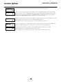
INSTALLER OPTS
This section contains the Installer’s Code, Walk Test Code and System Reset options.
INSTALLER OPTS
(00)
INSTALLER CODE
(0)
WALK TEST CODE
(1)
Installer’s Code. You can program a new Installer’s Code. The default setting is ‘5555’ for the 4-digit
option, or ‘555555’ for the 6-digit option. Enter a new code, using numbers from 0 to 9 only. Use the
installer’s code to enter the [*][8] Installer’s Programming menu. Change this code from the default
setting before programming is complete, to ensure the security of the system.
The Walk Test code gives a user access to the Walk Test Mode. When a user enters the Walk Test code at
a system keypad, they will have access to the following menu options.
Local Walk Test, Local + Com Test, Silent Com Test, Disable Walk Test, Seismic Test
SYSTEM RESET
(2)
PRIVATE KEY
(3)
Perform a “System Reset” if a “Module Comm Fault” occurs. This turns off power to the Combus for 5
seconds. No programming will be lost and the time does not have to be reprogrammed.
The system uses the Private key, together with a randomly generated Public key, to encrypt
communications over the Combus, making them more secure.
Enter an 8-digit code for the private key. See also “Public Key Cycle” under System Times.
3
SYSTEM AREA
System Options
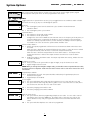
SYSTEM OPTIONS
(01)
SYSTEM OPTIONS
SYS TOGGLE OPT
This section contain options that are relevant to the entire system. System Toggle options, Keypad
Lockout options and System Times can all be programmed in this section.
Sys Toggle Options
SYS TOGGLE OPT
(0)
60 HZ AC
Y
XTAL TIMEBASE
N
FOLLOWS + ALARMS
N
6 DIGIT CODES
N
Toggle options are in question form. Use the [*] key to toggle between Yes and No to enable or disable
the feature. Use the [<] [>] keys to scroll through the options.
60 Hz AC?
YES = The incoming AC power from the transformer cycles at 60 Hz. The North American
standard is 60 Hz.
NO = The incoming AC power cycles at 50 Hz.
Crystal Time Base?
YES = The timebase is the internal crystal oscillator.
NO = The timebase is the AC power input.
Timing for the clock in the PC6010 can come from two sources. The frequency of the AC power, or
a crystal oscillator on the circuit board. The default is to use the frequency of the incoming AC
because it is normally very stable. However, in some locations, the stability of the AC frequency is
less reliable. If this is the case then the crystal oscillator should be used.
Follows includes Alarms?
YES = Enables all outputs programmed to follow zones to also annunciate alarms when those zones
are armed.
When the zone is disarmed, the output will follow the zone status (i.e. when the zone is violated
the output will activate; when the zone is restored the output will deactivate).
When the zone is armed the output follows the zone’s alarm status (i.e. the output will not
activate until the zone is violated. The output remains active until a user clears the alarm
memory).
NO = Disables the ability to latch alarm status. The output only follows zone activity, whether the zone
is armed or disarmed.
Six digit access codes?
YES = All access codes on the system will be 6 digits in length, except for the DLS access code.
NO = Regular 4 digit codes to be used.
NOTE: When you change from 4-digit to 6-digit codes, you should use DLS-3 to upload the user codes,
and then perform a Duplicate Code and Card check. Please refer to the DLS-3 manual for more
information.
N
Keypad tamper enabled?
YES = Keypad Tampers are used. This option should be enabled only if keypad tamper plates are
attached to the keypad.
NO = Keypad Tampers are disabled.
Y
Access Log On?
YES = The system will always make a log entry when it grants access to a user with an access card
NO = The system will not make a log entry when it grants access to a user with an access card, where
the user does not also enter an access code on the reader.
KEYPAD TAMPERS
ACCESS LOG ON
HI BATT CHARG
Y
DUPLICATE
CODE
N
YES = The battery charging current will be 1.4A.
NO = The battery charging current will be 360mA.
Duplicate Code Check?
YES = The system will not allow the programming of duplicate user codes. If a user code is entered
that matches any of the other 1000 users, the Installer code, or any other user code (or the
Duress derivative of any code), the keypad will sound an error tone and the data will not be
saved.
NO = The system will allow duplicate user codes to be programmed.
4
SYSTEM AREA
SYSTEM OPTIONS
SYSTEM TIMES
Keypad Lockout Options
KYPD LOCKOUT OPT
(1)
TOTAL BAD CODES
(0)
LOCKOUT DURATION
(1)
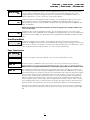
This section contains programming for the keypad and reader lockout features. After a programmed
number of incorrect attempts to enter an access or installer’s code, the keypad will lock users out.
This prevents users from performing any system function. A message “Keypad Lockout is Active” will
be displayed for the lockout duration. Keypad lockout is automatically enabled on all system
keypads. See “READER LOCKOUT” under “System Options” to enable the keypad lockout feature
on PC6820 readers.
Enter the number of incorrect code entries (from 000 to 255) required to activate keypad lockout.
The default setting is 005.
This section determines the number of minutes the keypad lockout will be active. Enter the duration
of the keypad lockout. Valid entries are from 000 to 255. The default setting is 015.
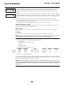
System Times
These times apply to the whole system.
SYSTEM TIMES
(2)
BELL CUTOFF
(00)
TLM DELAY
(01)
AC FAIL DELAY
(02)
AC DELAY
(03)
Program the amount of time (from 000 to 255 minutes) the bell output will activate for when an
alarm occurs. The factory default setting is 004 (4 minutes). Bell Cutoff is for any output (Bell, SW
Aux or PGM) that is programmed for Fire and Burg, Inv Fire and Burg, Burg Only, Inv Burg Only, Fire
Only, Inv Fire Only, and Tamper.
Program the amount of time (from 000-255 seconds) that a TLM Trouble will be delayed before it is
annunciated on the trouble group. The default is 060.
Program the amount of time (000-255 minutes) before an AC Trouble will be annunciated on the
trouble group. The default is 060.
Program the time (000-255 minutes) before the keypad will display an AC trouble in the fault list.
This will delay the “Trouble Group” annunciation and the “AC Fail TX Delay”. This delay does not
apply to the keypad Power light. If there is an AC trouble, the Power light on the keypad will turn off
immediately. The default is 000 minutes.
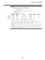
LOW COMBUS DELAY
(04)
Program the time (000-255 minutes) before a “Combus Low PWR” trouble will occur. The default is
000 minutes.
TLM TROUB. DELAY
(05)
Program the time (000-255 minutes) before a TLM trouble will be logged and displayed in the fault
list. The default is 000 minutes.
POLICE CODE TIME
(06)
DELAY AUTOARM
(07)
Program the amount of time (000 - 255 Minutes) before a Police Code Alarm reporting code will be
sent to the central station. A Police Code Alarm is sent when 2 zone alarms occur within the
programmed time. Default is 060 minutes.
Program the time in minutes that automatic arming can be delayed. Users can delay automatic
arming on assigned areas from a system keypad, or an PC6820 reader with a POST input. When the
programmed delay time expires, automatic arming will begin again. Users may delay automatic
arming as many times as desired. To delay automatic arming at a system keypad, users must enter
their access code, and then follow the available choices displayed on the keypad. To delay automatic
arming at an PC6820 reader, users must first pass an access card through the reader, and then
activate the POST input. The default delay is 030 minutes.
5
SYSTEM AREA
SYSTEM TIMES
SYSTEM OPTIONS
SYSTEM AREA
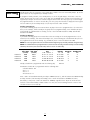
SYSTEM OPTIONS
ARM/DISARM MASK
PUBLIC KEY CYCLE
(08)
DAYLIGHT SAVINGS
(09)
The system uses the Public key, together with the programmed Private key, to encrypt communications
over the Combus, making them more secure. The Public key is generated randomly by the system.
Program how often the system changes the Public key. Valid entries are from 000-255 minutes. The
default is 020 minutes. See also “Private Key” under Installer Options.
Program the dates on which Daylight Savings time begins. You can program the dates for up to three
years. Program the dates in the YY/MM/DD format. At 0200 on the programmed day, the time will
automatically move ahead one hour to 0300. The default dates that are programmed are 00/03/26, 01/
03/25, and 02/03/31.
NOTE: All scheduled events that would have occurred during the hours of 0200 to 0300 will not
occur on these days.
STANDARD TIME
(10)
Program the dates on which Standard time begins. You can program the dates for up to three years.
Program the dates in the YY/MM/DD format. At 0300 on the programmed day, the time will automatically
move back one hour to 0200). The default dates that are programmed are 00/10/29, 01/10/28, and 02/
10/27.
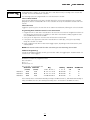
Arm/Disarm Mask
ARM/DISARM MASK
(3)
All areas are toggled to YES, by default. Areas toggled to NO in the mask cannot be armed from a
keypad. Areas toggled to NO can only be armed by automatic arming, keyswitch arming, over the infranet,
or via the DLS-3 software. The default is YES for all areas. Only areas which have been added to the system
can be programmed in the Arm/Disarm Mask. See “Area Section” programming.
Zone Supervision
ZONE
SUPERVISION
(4)
The zone is a normally closed loop to ground. The zone will be violated when it is open.
NO EOL
SINGLE
EOL
DOUBLE
EOL
All zones must have a 5600 ohm resistor across them. If the zone is shorted or open, it will be in a
violated condition. If the zone is open and programmed as a fire zone, it will be in a trouble condition.
NOTE: If zones are programmed for Fire or Links Supervisory, EOL resistors must be used.
This configuration will allow the panel to detect zone Faults (zone loop is shorted), zone tampers (zone
loop is open), open zones (alarm condition 11200 Ohms) and restored zones (5600 Ohms). If the zone is
disarmed and placed in the Tamper or Fault state, the keypad buzzer will sound from all partition keypads
(that the zone belongs to) for the length of Bell Time out or until the alarm is silenced (by user code or
Keyswitch zone). A zone trouble reporting code will be sent to the monitoring station (if programmed).
When the partition is armed and a zone is Tampered or Faulted, the keypad buzzer will sound from all
partition keypads (that the zone belongs to) for the length of Bell Time out or until the alarm is silenced,
but no burglary outputs will be activated and only the Trouble reporting code will be transmitted to the
monitoring station (if programmed). Refer to the System Manual for details on the hookup procedure.
All zones on the PC6010 can use Double End of Line resistors except Fire Zones (all types - Standard Fire
and Auto Verify Fire), Links Supervisory, and Links Answer zone types. These zones must only use Single
EOL.
6
SYSTEM AREA
DLS SECTION
DLS TOGGLES
DLS SECTION
PERIODIC CALLUP
SYSTEM AREA
Download Section
This section will allow you to program all options related to downloading.
DLS SECTION
(02)
Download Toggles
DLS TOGGLES
(0)
RING DETECT
N
DOUBLE CALL
N
DLS CALLBACK
N
PERIODIC DLS
N
USER ALLOWS SERV
N
Downloading Toggle Options. Toggle options are in the form of questions. Use the [*] key to toggle
between Yes and No to enable or disable the feature. Use the [<][>] keys to scroll through the options.
YES = The panel will answer after the programmed number of rings (program in the “# of Rings”
section, see below).
NO = Ring detect disabled. The only way downloading can occur is by using either the Usr Allows Srv
feature, or the Periodic Callup feature (see below).
YES = If the system detects 1 or 2 rings on the first call and then is called again within the programmed
period of time (000 to 255 seconds, see “2 Call Timer”), the system will answer the second call on the
first ring. This is useful for bypassing an answering machine that is sharing a telephone line with the
system.
NO = The system will only answer after the programmed number of rings is reached. See “# of Rings”.
YES = Callback is enabled. After the first connection to the system, both the computer and the system will
hang up. The computer will then wait for the system to call. If there is more than one downloading
computer, callback should be disabled.
NO = Callback is disabled. The downloading computer will have immediate access to the system, once
connected and accepted as valid.
YES = Periodic Downloading is enabled. Periodic downloading is used to allow the computer to execute
batch files. The computer must be waiting for a call for this feature work. See “Periodic Callup” for
programming the time of day, and the number of days in between periodic downloads.
NO = Periodic Downloading is disabled.
User Allows System Service?
YES = When this option is enabled, a Master user will have to turn on the “Allow System Service” option, for
Installer’s Programming to be accessible from either the DLS software, or a system keypad. Once the
Allow System Service option has been turned on, the system will answer incoming telephone calls for
60 minutes. If the “Ring Detect” option is also turned on, the panel will always answer incoming
telephone calls, but a Master user will still have to Allow System Service before a DLS-3 user can access
Installer’s Programming.
NO = Users will not have to turn on the Allow System Service option for Installer’s Programming to be
accessible from the DLS software or from a system keypad. The Allow System Service option will
not be available on the Master user menu. The control panel will not answer incoming telephone
calls unless the Ring Detect option is turned on.
YES = The DLS-3 will display all user codes, user options and user schedules.
SND USR CDS
Y
NO
= When this option is disabled, the PC6010 will send user codes, user options and user schedules
to the DLS-3 as %FF Hex. The rest of the programming options are uploaded normally.
Periodic Callup
(1)
Program the time and number of days between periodic downloads. (See “Periodic DLS” for enabling
Periodic Downloading.)
(0)
Program the number of days (from 001 to 255 days) between periodic downloads. The default setting is
030.
(1)
Program, in 24 hour time, the time of day the panel will call the computer for periodic downloading. The
default setting is 0000.
PERIODIC CALLUP
SET CYCLE DAYS
SET 24HR TIME
7
SYSTEM AREA
DLS SECTION
Other DLS Programming
Enter the telephone number for the DLS computer, if either Periodic DLS, or DLS Callback is enabled.
PHONE NUMBER
(2)
Programming Telephone Numbers
The total number of digits including the dial tone search and pauses must not exceed 31. Press the [*] key to
enter the telephone entry options menu. A “D” for dial tone search is already programmed as the first digit.
[0] Save
[1] Dial tone
[2] Pause 2 Seconds
[3] Pause 4 Seconds
[4] DTMF [*]
[5] DTMF [#]
[6] Clear Display
[7] Clear to End
[0]Select Save when you are finished programming the telephone number, to store it into the system’s
memory, or press [#] when finished entering the number.
[1]Select Dial Tone to add a 2 second dial tone search to the telephone number, which will be
represented by a letter “D” on the display. When the panel does a dial tone search, it looks for dial tone
before dialing the programmed telephone number.
[2]Select Pause 2 Seconds to add a 2 second pause to the dialing sequence, which will be represented by
the letter “E” on the display.
[3]Select Pause 4 Seconds to add a 4 second display to the dialing sequence, which will be represented
by the letter ‘A‘ on the display.
[4]Select DTMF [*] to input an asterisk, represented by a ‘B‘ on the display. The dialer will output the
same frequencies as a touch tone telephone would if the [*] key were pressed. (Frequency required to
disable call waiting.)
[5]Select DTMF [#] to add a ‘#’ represented by a ‘C’ on the display. The dialer will output the same
frequencies as a touch tone telephone would if the [#] key were pressed.
[6]Select Clear Display to clear the entire telephone number.
[7]Select Clear to End to clear the display from the character where the cursor was located to the end of
the display.
(3)
Panel Identifier Code. This six digit code will allow the computer to identify the panel that is calling. Each
system must have a different Panel ID code if Periodic DLS or DLS Callback is used. The default setting is
492100.
(4)
This 4 digit code must be the same on the DLS-3 computer and on the PC6010 system. If the code is
different, the system will NOT allow any uploading or downloading to take place. The default setting is
4920.
PANEL ID CODE
ACCESS CODE
2 CALL TIMER
(5)
# OF RINGS
(6)
ENABLE PC-LINK
(7)
This is the maximum allowable time in seconds between two telephone calls when the “Double Call”
option has been enabled. Valid entries are between 000 and 255 seconds. The default setting is 060. (See
“Double Call” for enabling the double call feature.)
This is the number of consecutive rings the panel must detect before answering the call. (See “Ring
Detect” or “User Allows Serv” for enabling ring detect.) Valid entries are between 001 and 255 rings. The
default setting is 008.
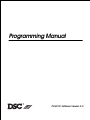
The PC-LINK module allows a direct connection between an on-site computer and the control panel. With
the PC-LINK, the computer can communicate with the panel at 9600 baud. Use a serial cable to link the
computer with the control panel. To download using PC-LINK:
1. Connect the PC-LINK connector to the header on the PC6010 board, as shown.
2. Enable PC-LINK in the Modem Configuration section of the DLS-3 software. The
software will display “PC-LINK Active” in the Status Bar of the Communications
window.
3. Open the appropriate account in the DLS-3, and select the function to be
performed (upload, download, etc.)
4. Go to any system keypad and enter Installer’s Programming and select “System”, then “DLS Section”,
then “Enable PC-LINK”. The keypad displays the message “PC-LINK Active (#) To Exit”.
5. Once the DLS communication is in progress, the panel will automatically exit the Installer Programming
mode.
6. When the desired DLS function(s) are complete, press the hang-up button on the Communications
window. This will disconnect the DLS from the panel.
7. If you are finished, remove the PC-LINK connector from the PC6010.
8
SYSTEM AREA
Communicator Section
COMMUNICATOR
(03)
COMMUNICATOR
MAIN ITEMS
All options concerning telephone line communications can be programmed, including telephone
numbers, reporting codes, account numbers and communicator options.
Main Items - Telephone #’s/Comm Format/Dialer Direction
MAIN ITEMS
(0)
1ST NUMBER
(0)
Programming for the telephone numbers of central stations the system will communicate with. The
PC6010 can call up to 3 different telephone numbers when reporting any event to a central station. The
second and third numbers can be used as backups if the first or second fail.
The panel will send the events programmed in the Dialer Direction section to the first telephone number.
By default, the panel sends all events through the first telephone number. See “Communicator Toggles”
for more details on the backup telephone numbers.
(1)
The panel will send the events programmed in the Dialer Direction section to the second telephone
number. The second telephone number can be used to as a backup for the first telephone number. See
“Communicator Toggles” for more details on the backup telephone numbers.
(2)
The panel will send the events programmed in the Dialer Direction section to the third telephone number.
The third telephone number can also be used as a backup for the first and/or second telephone numbers.
See “Communicator Toggles” for more details on the backup telephone numbers.
2ND NUMBER
3RD NUMBER
PGM TEL NUMBER
(0)
Programming Telephone Numbers
The total number of digits including the dial tone search and pauses must not exceed 31. Press the [*] key
to enter the telephone entry options menu. A “D” for dial tone search is already programmed as the first
digit.
[0] Save
[1] Dial tone
[2] Pause 2 Seconds
[3] Pause 4 Seconds
[4] DTMF [*]
[5] DTMF [#]
[6] Clear Display
[7] Clear to End
[0]Select Save when you are finished programming the telephone number, to store it into the system’s
memory, or press [#] when finished entering the number.
[1]Select Dial Tone to add a 2 second dial tone search to the telephone number, which will be
represented by a letter “D” on the display. When the panel does a dial tone search, it looks for dial tone
before dialing the programmed telephone number.
[2]Select Pause 2 Seconds to add a 2 second pause to the dialing sequence, which will be represented by
the letter “E” on the display.
[3]Select Pause 4 Seconds to add a 4 second display to the dialing sequence, which will be represented
by the letter ‘A‘ on the display.
[4]Select DTMF [*] to input an asterisk, represented by a ‘B‘ on the display. The dialer will output the
same frequencies as a touch tone telephone would if the [*] key were pressed. (Frequency required to
disable call waiting.)
[5]Select DTMF [#] to add a ‘#’ represented by a ‘C’ on the display. The dialer will output the same
frequencies as a touch tone telephone would if the [#] key were pressed.
[6]Select Clear Display to clear the entire telephone number.
[7]Select Clear to End to clear the display from the character where the cursor was located to the end of
the display.
NOTE: The PC6010 will only seize the telephone line if a telephone number has been programmed and
a reporting code has been entered for the event.
9
COMMS
FORMAT
(1)
There are 2 formats in the PC6010 for communicating with the central station: SIA and Contact ID. The
system must be programmed to use the same communications format as the receiver at the central
station. Each format can be programmed to use automatically generated reporting codes. Please see the
“Communicator Toggles” section. The default format is SIA.
NOTE: When using the Contact ID format, only the first four digits of the account code will be
used. When using this format make sure to program the last two digits of the account code as
“FF”.
SIA 1986 Format
The system ID codes and the customer ID codes must be six decimal digits in length. The reporting codes must be 2 digits.
NOTE: Do not program the keypad lockout reporting code or the printer buffer nearly full reporting code.
The SIA format will transmit a 6 digit account code, a 2 digit identifier code and a 2 digit reporting code. The 2 digit identifier is
preprogrammed by the PC6010. The 2 digit reporting code is programmed by the installer with any hex number from 01 to FE.
You can also program the system to automatically generate SIA reporting codes (see the Communicator Toggles section).
Please see Appendix B Reporting Codes, for a list of SIA reporting codes.
Contact ID
The System ID code and Customer ID codes must be 4 decimal digits. The reporting codes must be 2 digits. Substitute the HEX
digit “A” for the zero (0). To prevent the panel from reporting an event, the reporting code should be programmed as [00] or [FF].
NOTE: Do not program the Opening After Alarm, Buffer Nearly Full, Installer Lead In and Installer Lead Out reporting
codes.
Zone Alarms and Restorals can be programmed to send different messages to the monitoring station. For example, if the
Reporting code for zone 5 is programmed with ‘34’, the monitoring station will receive the message ‘*BURG* - ENTRY/EXIT - 5’,
where 5 is the number of the zone which has been activated. Please see Appendix B Reporting Codes, for a list of Contact ID
reporting codes.
You can also program the system to automatically generate Contact ID reporting codes (see the Communicator Toggles section).
10
SYSTEM AREA
DIALER DIRECTION
(1)
ALAR
M / RESTORE
ALARM
Y
COMMUNICATOR
MAIN ITEMS
This section determines which reporting codes are sent to the selected telephone number. All reporting
codes can be programmed to communicate to any or all of the telephone numbers. By default, all
reporting codes are sent to telephone number 1 only. See “Comms Toggles” for using telephone
numbers 2 and 3 as backup telephone numbers.
YES = The following reporting codes are transmitted to the selected telephone number. See
“Reporting Codes” for a description of these groups of reporting codes.
•
Zone Alarms & Restorals
•
Zone Troubles & Restorals
•
Duress Alarms & Restorals
•
Module Tamper Alarms & Restorals
•
Police Code Alarms & Restorals
NO = Alarm and Restoral reporting codes are not sent.
OPEN/CLOSE
N
YES = The following reporting codes are transmitted to the selected telephone number. See
“Reporting Codes” for a description of these groups of reporting codes.
•
•
•
Openings and Closings by Users 001-128, Users 129-1000
Miscellaneous Openings & Closings
Momentary / Maintained Keyswitch Openings & Closings
NO = Opening and Closing reporting codes are not sent.
ALL OTHERS
N
YES = The following reporting codes are transmitted to the selected telephone number. See
“Reporting Codes” for a description of these groups of reporting codes.
•
•
•
•
•
•
NO = All
SYSTEM ID CODE
(3)
System Maintenance
6400 Maintenance
6204 Maintenance
6820 Maintenance
6442 Maintenance
6443 Maintenance
other codes are not sent.
When a reporting code is sent to the central station, a six digit account code is also sent to identify the
customer. Each area has its own account code (See “Customer ID Code”). But for reporting codes that
do not pertain to a particular area, such as AC line trouble etc., the system ID code is sent to identify the
panel. The system ID codes and the customer ID codes must be six decimal digits. The reporting code
groups that send the system ID code are:
• Module Tamper Alarms & Restorals
• System Maintenance
• 6400 Maintenance
• 6204 Maintenance
• 6820 Maintenance
• 6442 Maintenance
• 6443 Maintenance
Note: 6442 events may use the Customer ID Code or the System ID Code depending on if the event
is an area or system event.
11
SYSTEM AREA
COMMUNICATOR
COMMS TOGGLES
Communicator Toggles
COMMS TOGGLES
(1)
COMMS ENABLED
Y
DTMF DIALING
Y
PC ID
N
PC ON AUTO ARM
Y
TLM ENABLED
Y
TLM AUD BELL
Y
FTC AUD BELL
N
RINGBACK
N
Select options relevant to the telephone line communications of the panel. Toggle options are given in
the form of a question. Use the [*] key to toggle between [Y]es and [N]o to enable or disable the feature.
Use the [<][>] keys to scroll through the options.
Communications are enabled?
YES = The communications function is enabled.
NO = The communications function is disabled. No reporting codes will be transmitted to the central
station. Downloading using DLS-3 software will work with the communicator disabled.
DTMF dialing enabled?
YES = The dialer will use DTMF dialing.
NO = The dialer will use pulse dialing.
Partial Closings Identified?
YES = When using SIA, and when a zone is bypassed, unbypasssed, disabled, or enabled, the panel will
log and transmit the appropriate SIA identifier for the event, along with the zone alarm reporting
code. This will occur whether the zone was bypassed, unpassed, disabled, or enabled manually, or
automatically when the panel is armed or disarmed. The partial closing reporting code must be
programmed for this feature to work.
NO = The panel will only send the partial closing reporting code when zones are bypassed, unbypassed,
disabled, or enabled when the area is armed. However, it will still identify the zones in the event
buffer.
NOTE: If Partial Closings are used to identify alarms or restorals, the Alarm or Restoral reporting code
must be programmed for the feature to function properly.
Partial Closings on Auto Arming?
YES = The panel will send the partial closing reporting code to the central station when a zone is force
armed (temporarily bypassed) by an auto arm. If the option “PC ID” is enabled, and if the panel is
programmed to transmit using SIA, the force armed zone will be identified by sending the bypass
identifier and the zone alarm reporting code after the partial closing reporting code. See the
“Zone Operation” section in the System Manual for more information on force arming.
NO = No partial closing reporting code will be sent when zones are force armed during auto arming.
Telephone Line Monitoring Enabled?
YES = The system tests for telephone line faults. If a fault is detected, the trouble is annunciated on the
keypads. A telephone line trouble is generated when the line voltage drops below 3 volts for more
than 30 seconds.
NO = Does not test for telephone line faults.
Telephone Line Monitoring has Audible Bell Alarm?
YES = If there is a Telephone Line trouble and an area is armed, the bell outputs for the armed area will
be activated, along with the keypad annunciation. The bell outputs are any outputs (Bell, SW Aux
or PGM) programmed for “FIRE AND BURG”, “INV FIRE/ BURG”, “BURG ONLY” and “INV BURG
ONLY”.
NO = If there is a Telephone Line trouble, the panel will annunciate the trouble at the keypad only.
Should a Failure to Communicate sound the Bells?
YES = If an area is armed, the bell outputs for the armed area will sound when the PC6010 fails to
communicate with the central station.
NO = A failure to communicate will not cause the PC6010 to sound the bells.
Enable Ringback?
YES = The Ringback option is enabled. A successful communication of a closing to the central station will
be annunciated by the keypads beeping 5 times. Only the keypads belonging to the area that sent
the communication will beep.
If communications are being sent to more than one telephone number, keypads will sound the
ringback after the event(s) have been successfully communicated to each telephone number.
NO = The Ringback option is disabled.
NOTE: Ringback must be enabled on a commercial burglar alarm system.
12
SYSTEM AREA
COMMUNICATOR
COMMS TOGGLES
SYSTEM AREA
COMMUNICATOR
COMMS MISC
RINGBACK SQUAWK
N
PERIODIC TX ?
N
EUROPE DIAL
N
DEFAULT DIAL
Y
PH 1-2 BACKUP
N
PH 1-3 BACKUP
N
PH 2-3 BACKUP
N
AUTO SIA
N
Ringback squawk enabled?
YES = Ringback Squawk option is enabled. If both Ringback and Ringback Squawk are enabled, then after
a successful communication of a closing, the Fire/Burg, Inv Fire/Burg, Burg and Invert Burg outputs
for that area will squawk 4 times.
NO = Ringback Squawk option is disabled.
NOTE: Ringback must be enabled for this feature to function.
Periodic Test Transmission?
YES = The panel will send a test transmission to the central station. See “TEST CODE TX” for information
on programming the time of day, and the frequency the code is sent. See “SYSTEM MAINT” for
programming the reporting code.
NO = The panel will not send a test transmission.
European Dialing?
YES = When the communicator is pulse dialing, the contact closure to the telephone line is made in a 67/33
make/break ratio. This is the European standard method of dialing.
NO = The contact closure to the telephone line is made in a 60/40 make/break ratio. This is the American/
Canadian standard method of dialing.
Dial if No Dial Tone Present?
YES = If the first attempt by the panel to call the central station fails, on every subsequent attempt the
panel will dial regardless of the presence of dial tone.
NO = If a ‘D’ for dial tone search precedes the telephone number, the panel will not dial if a dial tone is
not present. See “PGM TEL NUMBER” for programming the telephone numbers with dial tone
search.
Telephone #2 backs up Telephone #1?
YES = The PC6010 will send the reporting codes to the 2nd telephone number if the 1st telephone
number fails to communicate with the central station after the programmed number of attempts. If
you enable this option, you should disable the dialer directions for the 2nd telephone number.
Otherwise the reporting codes will be sent to the 2nd telephone number, whether the 1st number
failed or not.
NO = Disabled. The 2nd telephone number does NOT back up the 1st telephone number.
Telephone #3 backs up Telephone #1?
YES = The PC6010 will send reporting codes to the 3rd telephone number, if the 1st telephone number
fails to communicate with the central station after the programmed number of attempts. If you
enable this option, you should disable the dialer directions for the 3rd telephone number.
Otherwise the reporting codes will be sent to the 3rd telephone number, whether the 1st number
failed or not. If “PH 1-2 BACKUP” is also enabled, then when 1st telephone number fails the
reporting codes will be sent to both the 2nd and 3rd telephone number.
NO = Disabled. The 3rd telephone number does NOT back up the 1st telephone number.
Telephone #3 backs up Telephone #2?
YES = The PC6010 will send the reporting codes to the 3rd telephone number, if the 2nd telephone
number fails to communicate with the central station after the programmed number of attempts. If
you enable this option, you should disable the dialer directions for the 3rd telephone number.
Otherwise the reporting codes will be sent to the 3rd telephone number, whether the 2nd number
failed or not. If “PH 1-2 BACKUP” is also enabled, then when 1st telephone number fails, the
reporting codes will be sent to the 2nd telephone number. If the 2nd telephone number fails, the
reporting codes will then be sent to the 3rd telephone number.
NO = Disabled. The 3rd telephone number does NOT back up the 2nd telephone number.
Auto SIA?
YES = If the SIA format is selected, the panel can be programmed to automatically generate all zone and
user code numbers, thus eliminating the need to program these items.
If the “Auto SIA” toggle option is enabled, the panel will operate as follows: If an event’s reporting
code is programmed as [00], the panel will not attempt to call the central station. If the reporting
code for an event is programmed as anything from [01] to [FF], the panel will automatically generate
the zone or user code number. See Appendix B for a list of the codes which will be transmitted.
The Communicator Call Direction options can be used to disable the reporting of events such as
openings and closings.
NO = The panel will operate as follows: If an event’s reporting code is programmed as [00] or [FF], the
panel will not attempt to call central station. If the reporting code for an event is programmed as
anything from [01] to [FE], the panel will send the programmed reporting code.
13
SYSTEM AREA
AUTO CONTACT ID
N
COMMUNICATOR
COMMS MISC
TEST CODE TX
Auto Contact ID?
YES = If the Auto Contact ID option is enabled, the panel will operate as follows: If an event’s reporting
code is programmed as [00], the panel will not attempt to call the central station. If the reporting
code for an event is programmed as anything from [01] to [FF], the panel will automatically generate
the zone or access code number. See Appendix B for a list of the codes which will be transmitted.
The panel will automatically generate all zone and access code numbers, eliminating the need to
program these items.
NO = The panel will operate as follows: If an event’s reporting code is programmed as [00] or [FF], the
panel will not attempt to call central station. If the reporting code for an event is programmed as
anything from [01] to [FE], the panel will send the programmed reporting code.
Communicator Miscellaneous
Program other options relating to the communications of the panel.
COMMS
MISC
(2)
MAX. ATTEMPTS 1
(0)
Program the number of dialing attempts from 000 to 255 that the panel will make before a Failure To
Communicate (FTC) trouble occurs for telephone number one. The default number of attempts is 010.
NOTE: Do not program this section with 000.
MAX. ATTEMPTS 2
(1)
Program the number of dialing attempts from 000 to 255 that the panel will make before a Failure To
Communicate (FTC) trouble occurs for telephone number two. The default number of attempts is 010.
NOTE: Do not program this section with 000.
MAX. ATTEMPTS 3
(2)
AC FAIL TX DELAY
(3)
ZONE TX DELAY
(4)
Program the number of dialing attempts from 000 to 255 that the panel will make before a Failure To
Communicate (FTC) trouble occurs for telephone number three. The default number of attempts is 010.
NOTE: Do not program this section with 000.
Enter the time in minutes, that an AC trouble on the main panel must be present, before the AC trouble
reporting code will be logged or communicated. Valid entries are from 000 to 255. The default setting is
060.
Enter the time in seconds that the panel will delay the communication of a zone alarm. Valid entries are
from 000 to 255. The default setting is 000. If the panel is disarmed within the programmed time, no alarm
communication will be sent. See “TX DELAY?” under zone toggle options to enable the transmission delay
on each zone.
Test Code Transmission
TEST CODE TX
(5)
Test Code Transmission. To have the panel send test transmissions, you must program the time of day, the
number of days between test transmissions and the test transmission reporting code. You must also enable
the “PERIODIC TX?” communications toggle option.
(0)
Enter the number of days between test code communications. Valid entries are from 001 to 255. The
default setting is 030.
(1)
Enter the time of day the panel will send the test code. Program the time in 24-hour format HH:MM. The
default setting is 0000.
SET CYCLE DAYS
SET 24HR TIME
14
SYSTEM AREA
COMMUNICATOR
REPORTING CODES
Reporting Codes
REPORTING
ZONE
CODES
(3)
ALARM
(00)
ZONE
RESTORE
(01)
ZONE
TROUBLE
(02)
ZONE
TROB.REST
(03)
MOD TAMP ALARM
(04)
PC6501
Reporting codes are 2 digit codes which are sent to the receiver at the central station, along with the area ID
code for each transmission. They identify the type of alarm, and other events to the central station. Once you
have selected which group of reporting codes to program, use the arrow keys to scroll through the
reporting codes. Please see Appendix B for a table of recommended Contact ID reporting codes, and
automatically generated SIA reporting codes.
Enter a 2-digit number for each code you need to program. To disable a reporting code, program it with FF
(default setting). To enter Hex digits, press the [*] key when entering the code, to call up the Hex digit entry
menu, and to “Save and Exit” from the Reporting Codes menu.
For example:
to enter AB, press [*][1][*][2]
to enter A2, press [*][1][2]
Alarm Reporting Codes for Zones 001 to 256. Momentary and maintained arm zones will send the
reporting code programmed in this section for a closing. All reporting codes are programmed as [FF] at
default.
Restoral Reporting Codes for Zones 001 to 256. The zone restoral will be sent to the central station when a user
clears the alarm. Momentary and maintained arm zones will send the reporting code programmed in this section
for an opening. All reporting codes are programmed as [FF] at default.
Zone Trouble Reporting codes for zones 001 to 256. The system will send zone trouble reporting codes (if
programmed) when there is a zone trouble on standard fire and auto verifying fire zones, or when a tamper
occurs on other zone types. All reporting codes are programmed as [FF] at default.
Zone Trouble Restoral Reporting codes for zones 001 to 256. The system will send zone trouble reporting
codes (if programmed) when zone troubles are restored on standard fire and auto verifying fire zones, or when
tampers are restored on other zone types. All reporting codes are programmed as [FF] at default.
Program reporting codes for tamper alarms on modules.
KEYPADS
(0)
PC6400
There are 16 keypad tamper alarm reporting codes, one for each keypad that can be enrolled on the
system.
This is the PC6400 tamper alarm reporting code.
RS-232
(1)
(3)
There are 30 reporting codes for tamper alarms on PC6108 zone expansion modules. The maximum
number of expansion modules you will use is 30. (30 x 8 zones = 240 zones + 16 zones on the main panel
= 256 zones)
There are 9 module tamper alarm reporting codes, one for each PC6216 module that can be enrolled onto
the system.
(4)
There are 16 module tamper alarm reporting codes, one for each PC6204 module that can be enrolled onto
the system.
PC6108 ZONE EXP
(2)
PC6216 16 O /
P
/P
PC6204
PC6820
O/P
ACCESS
(5)
There are 16 module tamper alarm reporting codes sections, one for each PC6820 Access Control module
that can be enrolled on the system.
This is the PC6442 tamper alarm reporting code.
PC6442
APU
(6)
PC6443
This is the PC6443 tamper alarm reporting code.
ODS
(7)
15
Reporting Codes for the restoral of module tampers.
MOD TAMP RESTORE
(05)
PC6501
KEYPADS
(0)
There are 16 keypad tamper restoral reporting codes, one for each keypad that can be enrolled onto
the system.
This is the PC6400 tamper restoral reporting code.
PC6400
RS-232
(1)
PC6108 ZONE EXP
(2)
(3)
There are 9 tamper restoral reporting codes, one for each PC6216 module that can be enrolled onto the
system.
(4)
There are 16 module tamper restoral reporting codes, one for each PC6204 module that can be enrolled
onto the system.
(5)
There are 16 module tamper alarm restoral reporting codes sections, one for each PC6820 Access Control
module that can be enrolled on the system.
PC6216 16 O / P
PC6204
PC6820
PC6442
There are 30 reporting codes for tamper restorals on PC6108 zone expansion modules. The maximum
number of expansion modules you will use is 30.
O/P
ACCESS
This is the PC6442 tamper restoral reporting code.
APU
(6)
PC6443
This is the PC6443 tamper restoral reporting code.
ODS
(7)
Reporting Codes for Closings.
CLOSINGS
(06)
Reporting codes for users 0001-0128. See “Miscellaneous Closings” for additional users.
USERS 1-128
MISC
CLOSINGS
(07)
Miscellaneous Reporting Codes for Closings.
CLOSING
129-1000
PARTIAL
CLOSING
AUTOARM
ABORT
AUTOARM
CLOSING
6442 APS CLOSING
6443 ODS CLOSING
Closing 129 - 1000 - This reporting code will be sent when any user code from 0129-1000 is used to
arm an area. In order to identify the user which armed the area the panel will first perform a “User
Log” for the user that armed the area and then log/transmit the Closing 129-1000 reporting code.
If an area auto-arms, and some zones were open, the system will force arm the open zones. The
system will send the partial closing reporting code to the central station, along with the alarm
reporting codes of the zones that are open. The partial closing reporting code will also be transmitted
if zones were manually bypassed.
If automatic arming is cancelled, this reporting code will be sent.
When the system auto-arms, the panel will send the auto-arm reporting code to the central station.
The system sends this reporting code when area(s) are closed by the APS software.
The system sends this reporting code when area(s) are closed by the ODS software.
16
SYSTEM AREA
KEYPAD
COMMUNICATOR
REPORTING CODES
If a user enters too many incorrect access codes (see “Total Bad Codes” under “Keypad Lockout
Options” for programming the number of incorrect code entries), the keypad will be locked out,
preventing anyone from attempting to enter any more access codes. When keypad lockout occurs, the
keypad lockout reporting code is sent to the central station.
LOCKOUT
Reporting Codes for Openings.
OPENINGS
(08)
USERS
MISC
Reporting codes for users 0001-0128. See “Miscellaneous Openings” for additional users.
1-128
OPENINGS
(09)
OPENING
Miscellaneous Reporting Codes for Openings.
129-1000
OPEN AFTER ALARM
6442 APS OPENING
6443 ODS OPENING
(10)
Opening After Alarms Reporting Code -The system sends this code to the central station when the
system is disarmed after there was an alarm.
Open Automatic - This reporting code will be sent any time an area on the system is autodisarmed.
OPEN AUTOMATIC
SYSTEM MAINT
Opening 129 - 1000 - This reporting code will be sent when any user code from 0129-1000 is used to
disarm an area. In order to identify the user which disarmed the area the panel will first perform a
“User Log” for the user, and then log/transmit the Opening 129-1000 reporting code.
Miscellaneous Reporting Codes for Openings.
The system sends this reporting code when area(s) are opened by the APS software.
The system sends this reporting code when area(s) are opened by the ODS software.
System Maintenance Reporting Codes. There are 27 reporting codes for events relating to the operation and
maintenance of the system. The reporting codes are:
• Battery Trouble and Battery Restoral - If the battery voltage on the PC6010 main panel is weak,
disconnected or if the battery fuse fails, a battery trouble occurs, and the battery trouble reporting code is
sent. When the battery voltage and fuse are restored, the battery restoral code is sent. See the “Viewing
Fault Conditions” section in the System Manual.
• AC Line Trouble and AC Line Restoral - If the incoming AC voltage to the AC terminals fails, an AC
trouble occurs and the AC trouble reporting code is sent to the central station after the AC Fail Tx Delay
has elapsed (see “AC FAIL TX DELAY”). When the incoming AC is restored, the AC restoral reporting code
is sent to the central station. See the “Viewing Fault Conditions” section in the System Manual.
• Main Bell Trouble and Main Bell Restoral - If a bell trouble occurs, either from the bell fuse failure or the
open bell terminals, the Main Bell Trouble reporting code will be sent to the central station. When the
trouble condition is restored, the Main Bell Restoral reporting code will be transmitted.
• Main Aux Trouble and Main Aux Restoral - If an auxiliary voltage supply trouble occurs, the Main Aux
Trouble reporting code is transmitted, and when the auxiliary voltage supply is restored, the Main Aux
Restoral code is transmitted.
• Combus Low Power and Combus Low Power Restoral - When a module on the system has low power,
the Combus Low Pwr reporting code will be transmitted. When the power is fully restored, the Combus
Restoral reporting code will be sent.
• Combus Comm Fault and Combus Comm Restoral - When the system loses communication with a
module, the Combus Trouble reporting code will be transmitted, and when communications resume the
Combus Restoral reporting code will be sent.
• Backbone Trouble and Backbone Restoral - When the system loses communication with a backbone
module, the Backbone Trouble reporting code will be transmitted, and when communications resume the
Backbone Restoral reporting code will be sent.
• TLM Failure - A TLM reporting code will be sent over the backbone when a TLM trouble occurs.
17
• TLM Restoral - If there is a telephone line trouble, the PC6010 will not be able to communicate with the
central station until the telephone line is restored. When the line is restored, the system sends TLM
Restoral reporting code.
• FTC Restoral - If a failure to communicate trouble occurs, where the PC6010 could not get through to the
central station, the next time the panel attempts to communicate and is successful, it will also transmit the
FTC restoral reporting code.
• Periodic Test - This is the reporting code that is sent to the central station to test communications.
• Buf Near Full - This reporting code is sent only if a printer is not being used, or the printer is off line for
2500 events.
• User System Test - When the user does a communications test, the User System Test reporting code is
sent to the central station to test communications.
• Walk Test Enable and Walk Test Disable - When Walk Test mode is entered the system sends the walk
test enable code. When the walk test is ended, the system sends the walk test disable code.
• DLS Lead In and DLS Lead Out - If the DLS Lead In reporting code is to be used the DLS callback feature
must be enabled. (See “DLS callback” under “DLS Toggles”).
When a computer calls the PC6010 panel, after connection is made, both the panel and the computer will
hang up the telephone line. The panel will then transmit the DLS Lead In reporting code to the central
station. The panel will then call the computer and begin downloading. When the computer is finished
downloading to the panel, they will both hang up the telephone line, and the PC6010 will transmit the
DLS Lead Out reporting code to the central station.
NOTE: DLS Lead In/Out reporting code is only sent for DLS Call Back.
• Ins Lead In and Ins Lead Out - The Installer's Lead In reporting code is sent to the central station when an
installer enters the [*][8] installer’s programming mode. The Lead Out code is sent when the installer leaves
[*][8] installer’s programming.
• Links Test - If this code is programmed and Links Test Transmission is enabled (see Links Toggles), this
reporting code will be sent via the Links unit. This code will never be sent through the regular telephone
line.
6204 MOD MAINT
(11)
6820 MOD MAINT
(12)
6400 MOD MAINT
(13)
6442 MOD MAINT
(14)
6443 MOD MAINT
(15)
The PC6204 module maintenance reporting code section has reporting codes for sixteen modules, with 6
codes for each module, for a total of 96 reporting codes. The 6 codes for each module are Battery Trouble,
AC Line Trouble, Aux Supply Trouble, Battery Restoral, AC Line Restoral and Aux Supply Restoral. These
reporting codes are similar to the system maintenance reporting codes for the PC6010 main panel.
The PC6820 module maintenance reporting code section contains reporting codes for sixteen modules,
with 6 codes for each module, in total 96 reporting codes. The reporting codes for each module are: Battery
Trouble, AC Line Trouble, AUX Supply Trouble, Battery Trouble Restore, AC Line Restore, and AUX Suuply
Restore. The AC and DC trouble reporting codes will be transmitted when those trouble conditions occur.
The PC6820 trouble will be transmitted for any of the following conditions - Lock Device Failure, Aux Supply
Trouble, Reader supply trouble. These events are individually logged to the event buffer but this reporting
code will be sent to identify that one of these trouble conditions exists for the module. In order for the
specific problem to be located the event buffer should be uploaded or checked with the on-site printer/
viewable keypad buffer.
The PC6400 module maintenance reporting code section has 2 reporting codes, RS-232 Trouble and RS232 Restoral. If there is a problem that the RS-232 cannot transmit, the RS-232 Trouble reporting code is
sent to the central station. When the problem is cleared, and the RS-232 has successfully transmitted, the
RS-232 restoral is sent to the central station.
The PC6442 module maintenance reporting code section has 8 reporting codes for the PC6442 module.
The 8 codes are Battery Trouble, AC Line Trouble, Aux Supply Trouble, Battery Restoral, AC Line Restoral,
Aux Supply Restoral, RS232 Communications Trouble, and RS232 Communications Restoral. These
reporting codes are similar to the system maintenance reporting codes for the PC6010 main panel.
The PC6443 module maintenance reporting code section has 8 reporting codes for the PC6443 module.
The 8 codes are Battery Trouble, AC Line Trouble, Aux Supply Trouble, Battery Restoral, AC Line Restoral,
Aux Supply Restoral, RS232 Communications Trouble, and RS232 Communications Restoral. These
reporting codes are similar to the system maintenance reporting codes for the PC6010 main panel.
18
SYSTEM AREA
POLICE CODE ALARM
(16)
COMMUNICATOR
REPORTING CODES
Police Code Alarm is an additional alarm notification feature. When a zone on an armed area goes into
alarm, a timer (Police Code Time - see “System Times”) will begin. If during this time a second zone goes
into alarm, the area’s Police Code Alarm Reporting code will be transmitted (there is a Police Code Alarm
reporting code for each area). Any outputs programmed as Police Code for the area will also activate.
Additional police codes will only be sent once the police code restore has been transmitted for that area
(see “Police Code Restoral”).
Police Code Alarm will only function for burglary zones and only while the area is armed. This includes 24
hour Burg zones (24 Bell, Bell/Buzz, and Buzzer, Seismic Zone) The only zones that will activate the police
code are the following; Standard Delay; Auxiliary Delay; instant; interior; Interior Home Away; Delay Home
Away; 24 Hr Bell; 24 Hr Bell/Buzz; 24 Hr Buzzer; and the Seismic zones.
POLICE CODE REST
(17)
DURESS
CODES
(18)
The Police Code Restoral will be transmitted when all alarms are cleared from the area. A second police
code will only be sent once the Police Code Restore has been transmitted for that area.
Duress Code Alarm. This reporting code will be sent when a duress code is entered from any area
keypad.
Duress Code Restoral. This reporting code will be sent when the duress alarm has been acknowledged
by a user on any area. When you program the Duress Restoral Reporting code, you should use a
different reporting code than the duress alarm reporting code. This allows the Duress Restoral to
be Identified.
19
SYSTEM AREA
Links Module
LINKS
LINKS MODULE
These section options are relevant to the LINKS1000 operation.
MODULE
(4)
NOTE: Dial Tone Search must be included in the land phone number. See ‘Main Item’ for programming details.
1ST
NUMBER
(0)
2ND
NUMBER
(1)
3RD
NUMBER
(2)
DLS
NUMBER
(3)
LINKS
Phone Number 1. If the LINKS1000 module is enabled on the PC6010, this number will be used to back up
the land line first number should the telephone line fail.
Phone Number 2. If the LINKS1000 module is enabled on the PC6010, this number will be used to back up
the land line second number should the telephone line fail.
Phone Number 3. If the LINKS1000 module is enabled on the PC6010, this number will be used to back up
the land line third number should the telephone line fail.
This number is used if downloading is to be done or backed up with the LINKS1000 unit.
Enter the telephone number for the downloading computer if User Call Up, Periodic DLS, or DLS
Callback is enabled. See “PGM TEL NUMBER” for entering a telephone number and options when
programming the phone number. See the “Communicator Options” section of this manual for
instructions on programming telephone numbers.
This section contains all options related to the use of the LINKS1000 module.
TOGGLES
(4)
LINKS
MODULE
N
LINKS module enabled?
YES = The LINKS1000 module enabled. This selection must be enabled in order for the LINKS1000 unit to
operate.
NO = LINKS1000 module disabled.
NOTE: Once the LINKS1000 module is selected the Main PGM OUT automatically changes to Links
Operation and cannot be reprogrammed until the module is deactivated.
PERIODIC
TX
N
LINKS periodic test transmission?
YES = A test transmission is sent by the panel for the LINKS1000 unit. (See ‘Tx Cycle Days’ and ‘Tx Cycle
Time’.)
NO = No test transmission is sent by the panel for the LINKS1000 unit.
NOTE: The Links Test Transmission Code can be programmed under system maintenance of the
reporting code section.
TX CYCLE DAYS
(5)
TX CYCLE TIME
(6)
Test transmission cycle days?
Enter the number of days between test code communications. Valid entries are from 001 to 255. The
default setting is 030.
Test transmission cycle time?
Enter the time of day the test code will be communicated. Times are entered using 24Hr format HH:MM.
The default setting is 0000.
20
SYSTEM AREA
SW AUX OUTPUT
SYSTEM AREA
MAIN BELL OUTPUT
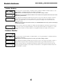
Switched Auxiliary Output
SW AUX OUTPUT
(04)
The switched auxiliary output terminal on the main panel is a 12 volt power supply. It can be activated and
deactivated by any one of 56 programmable output options. Normally the output energizes when it is
activated. The output will de-energize when it is activated if any “INV” options are selected. The switched
auxiliary output, for some options can also be programmed to activate for only selected areas.
Program the output type from the list of 56 output options (see “Programmable Output Options”).
Depending on which output option you select, you may also need to program the area(s) the output will
be active on, which zone the output will follow, which date schedule the output will follow, and/or a
pulse timer for the output.
Typically, this output is used for providing power to latching type devices that require a power
interruption in order to reset.
For example:
The SW AUX output has been programmed for Sensor Reset and enabled on area 1 and area 2. User 005
has been assigned to area 1. When user 005 select answers Yes to “Do you want to reset detectors?”, the
output will deactivate for the amount time programmed in “PGM Pulse Time”.
NOTE: Refer to “Programmable Output Options” for a list of available programmable output types.
Main Bell Output
MAIN BELL OUTPUT
(05)
The bell output on the main control board can be programmed to activate for any one of the 56
programmable output options, on any number of areas. The BELL+ terminal is always 13.8 VDC. The BELLterminal is normally 12.6 VDC. This voltage difference is required for bell circuit supervision. When the bell
output is activated, the panel will switch BELL- to ground.
The Bell output is supervised. If no alarm warning devices are in use, connect a 1000 ohm resistor (brown,
black, red, gold) across BELL+ and BELL– to prevent the panel from displaying a trouble condition.
Program the output type from the list of 56 output options (see “Programmable Output Options”).
Depending on which output option you select, you may also need to program the area(s) the output will
be active on, the zone the output will follow, the date schedule the output will follow, and/or a pulse
timer for the output.
NOTE: Refer to “Programmable Output Options” for a list the available programmable output types.
21
SYSTEM AREA
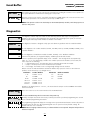
PGM Outputs
PGM OUTPUTS
PGM OUTPUTS
(06)
Main PGM1 and PGM2 Outputs
MAIN PGM1 OUT
(0)
MAIN PGM2 OUT
(1)
The PGM outputs can be programmed to activate for any one of the 56 options listed in the PGM
outputs list. Normally the outputs energize when they are activated. The outputs will de-energize when
they are activated if any “INV” options are selected. The default output type is 25 (Holdup).
Program the output type from the list of 56 output options (see “Programmable Output Options’).
Depending on which output option you select, you may also need to program the area(s) the output will
be active on, the zone the output will follow, the date schedule the output will follow, and/or a pulse
timer for the output. The default output type is 25 (Holdup).
NOTE: Refer to “Programmable Output Options” for a list of the available options.
PC6204 Options
6204
OPTIONS
(2)
Each relay of any 4204 relay module can be programmed to activate for any one of the 56 options listed
in the PGM outputs list. Normally each relay will be de-energized, and energizes when it is activated. The
relay will normally be energized, and then de-energized when it is activated, if any “INV” option is
selected. Output 1 will always be active if left at the default of (15) Combus power, unless there is no
incoming Combus power.
Program the output type from the list of 56 output options (see “Programmable Output Options”).
Depending on which output option you select, you may also need to program the area(s) the output will
be active on, the zone the output will follow, the date schedule the output will follow, and/or a pulse
timer for the output.
NOTE: PC6202 #01 Output #1 is default a “Burg Only” (02) output. Do not use this output to
repower Combus without changing the output type to “Combus Power” (15).
PC6216 Options
6216
OPTIONS
(3)
CUSTOM GROUP
(01)
(09)
A maximum of nine PC6216 output modules can be connected to the system.
First select the PC6216 to be programmed, then select the option it is going to be programmed for. The
PC6216 follow one of nine custom PGM output groups.
The custom group allows each of the 16 outputs to be individually programmed with one of the 56
options listed in the PGM outputs list. Each output is programmed in the “4216 CUSTOM” section.
PC6216 Custom
6216
CUSTOM
(4)
CUSTOM GROUP
(01)
(09)
This section is for programming each of the 9 custom groups for different options. Program one option
for each of the 16 outputs. You can program each output for any of the 56 listed programmable output
options. You can assign each PC6216 modules to one of these groups (see “PC6216 Options”).
Depending on which output option you select, you may also need to program the area(s) the output will
be active on, the zone the output will follow, the date schedule the output will follow, and/or a pulse
timer for the output.
22
SYSTEM AREA
PGM OUTPUTS
PGM Pulse Times
PGM PULSE TIMES
(5)
This section will allow you to select the amount of time a programmable output will remain active, after
being triggered.
NOTE: The system will reset the outputs when a user attempts to clear alarms, regardless of
whether or not all the alarms are cleared.
(0)
The main bell, switched auxiliary or any of the PGM outputs programmed for “Utility Output” and
“Sensor Reset”, can be active from 000 to 255 seconds. The default setting is 005.
(1)
Any output programmed for “Chime Pulse” can be active from 000 to 255 seconds. The default setting is
002.
UTILITY/SENSOR
CHIME PULSE
DURESS PULSE
(2)
Any output programmed as Duress Output for the selected area will activate for 000 - 254 minutes. If you
program 255 for the Duress Pulse time, the output will latch on, until a user enters an access code. The
default Duress Pulse time is 005 minutes.
NOTE: The Duress Pulse timer will follow the minute rollover. This will cause the Duress Pulse time to
be less than one minute in most cases. It is recommended that a Duress Pulse time of more than 1
minute be programmed.
23
Programmable Output Options
SYSTEM AREA
PGM OUTPUTS
The output will activate when any fire or zone alarm occurs on any of the selected areas.
FIRE AND BURG
(00)
The output will deactivate when any fire or zone alarm occurs on any of the selected areas.
INV FIRE/BURG
(01)
The output will activate when any zone alarm occurs on any of the selected areas.
BURG ONLY
(02)
The output will deactivate when any zone alarm occurs on any of the selected areas.
INV BURG ONLY
(03)
The output will activate when any fire alarm occurs on any of the selected areas.
FIRE ONLY
(04)
The output will deactivate when any fire alarm occurs on any of the selected areas.
INV FIRE ONLY
(05)
UTILITY OUTPUT
(06)
SENSOR RESET
(07)
AREA STATUS
The output will activate when a user answers YES to “Do you want to activate door strike?” at any keypad
in any of the selected areas.
NOTE: This output will follow the “Utility/Sensor” PGM pulse time.
The output will deactivate when a user answers YES to “Do you want to reset detectors?” at any keypad in
any of the selected areas.
NOTE: This output will follow the “Utility/Sensor” PGM pulse time.
The output will activate when any of the selected areas are armed.
(08)
LATCHED STROBE
(09)
TROUBLE OUTPUT
(10)
The output will activate when any alarm occurs on any of the selected areas. The output will stay activated
until the area that caused the alarm is disarmed. The following alarms DO NOT activate the latched strobe
output: Standard Fire Zone Alarm, Auto-Verify Zone Alarm.
The output will activate when a trouble condition is present on any of the selected areas.
If a system trouble occurs (i.e. loss of time, TLM) all trouble outputs will activate.
The output will activate during exit and entry delay on any of the selected areas.
COURTESY PULSE
(11)
CHIME FOLLOWER
(12)
The output will activate when door chime is activated on any of the selected areas, and deactivate when
the chime pulse timer expires. (See “Chime Pulse” under “PGM Pulse Times”.)
The door chime activates when a zone is opened and activates again when a zone is closed. For the door
chime feature to work, the user must enable the door chime, and the installer must enable the door chime
for the individual zones (see “Chime Function” under “Zone Options”).
The output will activate when a telephone line trouble is present.
TLM ONLY
(13)
FAILURE TO COMM
(14)
The output will activate when a Failure to Communicate Trouble is present. The output will stay activated
until the trouble is cleared by the user, or until a successful communication is sent to the central station.
This output will remain active at all times unless a system reset is ordered by the main panel.
COMBUS POWER
(15)
READY STATUS
(16)
ZONE ALARM
(17)
The output will activate when all the zones in the area are closed, and the area is disarmed. If a zone
opens or the area is armed, the output will deactivate.
This output will annunciate when a selected zone has gone into alarm.
Any one of the 256 zones can be selected. If the zone is armed and goes into alarm, the output will
activate and remain active, even when the area the zone belongs to has been disarmed. The output will
remain active until the alarm is cleared.
24
SYSTEM AREA
ZONE FOLLOW
(18)
PGM OUTPUTS
This output will follow a selected zone. Any one of the 256 zones can be selected. If the zone is opened,
the output will activate. When the zone is closed the output will deactivate.
See “Follows + Alarms” for enabling the output to be a zone follower and zone alarm annunciator.
(19)
This output will be turned on for the selected area(s) when a duress type code is used to perform any
function. It will follow the duress output timer.
(20)
This output will activate when a programmed area(s) keypad buzzer activates for Entry Delays, Auto Arm
Pre-alert, 24 Hour Buzzer, Tamper and Door Strike.
DURESS OUTPUT
BUZZER FOLLOW
REMOTE OPERATION
(21)
This option can be remotely activated by area with DLS-3, and remains active until deactivated by the DLS3 package.
EXIT FOLLOW
This option will follow the exit delay timer of the area(s) it is assigned to.
(22)
This option will follow the entry delay timer of the area(s) it is assigned to.
ENTRY FOLLOW
(23)
DATE SCHEDULE
(24)
HOLD UP
(25)
SET
(26)
TROUBLE GROUP
(27)
This PGM output type may be programmed to follow any one of 99 date schedules. The schedule which the
output is programmed to follow may be activated at any time, and may remain on for up to 24 hours. See “Date
Schedule” for programming details.
This output type will activate when a Hold Up zone has been tripped for the selected area. The output will latch
on when activated. The output will remain active until a valid access code is entered. If the area is already
disarmed the output will remain active until an access code is entered.
This output will activate only when the selected area(s) are fully armed and will remain active until the area is disarmed.
The term “Fully Armed” refers to the area being armed with no zones bypassed, disabled or force armed and all
interior zones armed. The output will deactivate if one or more zones in the area(s) are in alarm. If the output is
programmed to follow more than one area, then the output will not activate until all assigned areas are fully armed.
There are four different “Trouble Groups” that this output type may follow. Each output that is programmed
as Trouble Group may only follow one group at a time. The troubles are divided as follows:
Group #1
Group #2
Group #3
Group #4
6010 Battery Trouble
6010 AC Trouble
AC Trouble
6204 AC Trouble
6010 Battery Trouble
6010 AUX Supply Trouble
Battery Trouble
6010 AUX Supply Trouble
6010 TLM Trouble
6820 AC Trouble
6442 AC Trouble
6010 TLM Trouble
6010 FTC Trouble
6010 FTC Trouble
6010 Bell Circuit Trouble
6443 AC Trouble
6010 Bell Circuit Trouble
6010 Fire Trouble
6010 Fire Trouble
Module Comm. Fault
Module Communication Fault
6204 Battery Trouble
6204 Battery Trouble
6204 AUX Trouble
6204 AC Trouble
6820 Battery Trouble
6204 AUX Trouble
6820 AUX Trouble
6820 Battery Trouble
6820 Reader Power Trouble
6820 AC Trouble
6820 Lock Device Failure
6820 AUX Trouble
6442 Battery Trouble
6820 Reader Power Trouble
6820 Lock Device Failure
6442 AUX Trouble
6443 Battery Trouble
6442 Battery Trouble
6442 AC Trouble
6443 AUX Trouble
Zone Tamper
6442 AUX Trouble
6443 Battery Trouble
Zone Fault
Seismic Detector Test Fault
6443 AC Trouble
6443 AUX Trouble
PC6442 Aps Comm. Fault
PC6443 ODS Comm. Fault
25
SYSTEM AREA
TAMPER
(28)
CONDITION.AL.
(29)
POLICE CODE.
(30)
MOMENTARY O/P
(31)
MAINTAINED O/P
(32)
BATTERY TEST
(33)
AUXILIARY ALRM
(34)
MEDICAL ALARM
(35)
SEISMIC PULSE
(36)
PGM OUTPUTS
This output will activate when a zone tamper (or zone fault) condition occurs and remain active for the duration
of Bell Time Out, for the selected area(s).
When assigned to one area, this output will activate when two alarms occur on that area within a
programmable amount of time (“Conditional Alrm”, Area Times section, the default is 10 minutes). If the area
is armed the output will remain on until the area is disarmed. If the area is disarmed and two alarms occur on
the selected area then the Conditional Alarm outputs programmed for that area will remain active until the area
the output is assigned to is armed. There is no alarm reporting code for this condition. Each area has its own
programmable Conditional Alarm Time. If the output is programmed for more than one area, then any two
alarms on one of the assigned areas will activate the output.
This programmable output will activate when the police code alarm would be logged/transmitted for the
selected area(s). The output will only deactivate when the alarms are cleared on the selected areas. See Police
Code under “Communicator - Reporting Codes” for more information.
After the system has been armed or disarmed normally, the output will turn on for 10 seconds. A normal
arming is when no zones have been manually bypassed or disabled. A normal disarming is when there
are no alarms in memory, and there were no zones disabled.
If there is a non-normal arming or disarming, the output will flash for 10 seconds. A non-normal arming
is when at least one zone has been manually bypassed or disabled. A non-normal disarming is when
there is at least one alarm in memory, or at least one zone was disabled.
After the system has been armed normally, the output will turn on. A normal arming is when no zones
have been manually bypassed or disabled.
After the system has been disarmed normally, the output will turn off. A normal disarming is when there
are no alarms in memory, and there were not zones disabled.
If there is a non-normal arming, the output will flash for 10 seconds and then remain on. A non-normal
arming is when at least one zone has been manually bypassed or disabled.
If there is a non-normal disarming, the output will flash for 10 seconds and then turn off. A non-normal
disarming is when there is at least one alarm in memory, or at least one zone was disabled.
After area 1 is disarmed, the panel will perform a 30 second battery check. During
this time this PGM output will activate. The output will control a relay to switch a
10 ohm load across the battery during the battery check. Connect the relay as shown
at right.
This output will activate when an Auxiliary zone alarm occurs (either 24
Auxiliary or the Auxiliary zone types) on the selected area(s). This output will not activate for tamper or
fault conditions of these zone types. The output will deactivate when the alarm is cleared.
This output will activate when a Medical zone alarm occurs on the selected area(s). This output will not
activate for tamper or fault conditions of this zone type. The output will deactivate when the alarm is
cleared.
This output is used to test seismic shock sensors. The output may be programmed to follow any Date
schedule from 02 to 99. This output must be assigned to the same Seismic Groups as the zone(s) it will
be testing. When the seismic test is performed, the seismic pulse output will activate for 13 seconds and
then deactivate. During the first 13 seconds of the test, if the zone does not activate, it will immediately
fail the seismic test. The zone must also be restored 10 seconds after the output deactivates, in order to
pass the test.
NOTES: Do not program the Seismic Pulse output to Date schedules 00 or 01. Scheduled Seismic Tests
will not occur while the PC6010 is in Installer’s programming.
ALARM
GROUP
(37)
INV AREA STATUS
(38)
Select an alarm group for the output. When there is an alarm in one of the zones assigned to the alarm
group, the output will activate. See “Zone Programming - Alarm Groups”. Alarm group outputs will not
activate during a walk test.
The output will deactivate when any of the selected areas are armed.
26
SYSTEM AREA
INV LATCHED STROBE
(39)
INV TROUBLE OUTPUT
(40)
INV ZONE ALARM
(41)
PGM OUTPUTS
The output will deactivate when any alarm occurs on any of the selected areas. The output will stay
deactivated until the area that caused the alarm is disarmed. The following alarms DO NOT trigger the
latched strobe output: Standard Fire Zone Alarm, Auto-Verify Zone Alarm.
The output will deactivate when a trouble condition is present on any of the selected areas.
This output will deactivate when the selected zone has gone into alarm. Any one of the 256 zones can be
selected. If the zone is armed and goes into alarm, the output will deactivate and remain off, even when the
area the zone belongs to has been disarmed. The output will remain off until the area is armed again.
INV ZONE FOLLOW
(42)
This output will follow a selected zone. Any one of the 256 zones can be selected. If the zone is opened, the
output will deactivate. When the zone is closed the output will activate.
INV DURESS OUTPUT
(43)
This output will be turned off for the selected area(s) when a duress type code is used to perform any
function. It will follow the duress output timer.
INV DATE SCHEDULE
(44)
This PGM output type may be programmed to follow any one of 99 date schedules. The schedule which the
output is programmed to follow may be activated at any time, and may remain on for up to 24 hours. See
“Date Schedule” for programming details.
INV HOLD UP
(45)
INV SET
(46)
This output type will deactivate when a Hold Up zone has been tripped for the selected area. The output will latch
off when activated. The output will remain off until the alarm is cleared. If the area is already disarmed the output
will remain off until the alarm is cleared.
This output will deactivate only when the selected area(s) are fully armed and will remain off until the area is disarmed.
The term “Fully Armed” refers to the area being armed with no zones bypass or force armed and all interior zones
armed. If the output is programmed to follow more than one area, then the output will not deactivate until all assigned
areas are fully armed.
INV TROUBLE GROUP
(47)
There are four different “Trouble Groups” that this output type may follow. Each output that is programmed
as Trouble Group may only follow one group at a time. See the Trouble Group output type for a list of the troubles
in each group.
INV TAMPER
This output will deactivate when a zone tamper (or zone fault) condition occurs and remain off for the duration
of Bell Time Out, for the selected area(s).
(48)
INV CONDITION.AL.
(49)
INV POLICE CODE.
(50)
INV AUX ALRM
(51)
INV MEDICAL ALM
(52)
INV SEISMIC PULSE
(53)
When assigned to one area, this output will deactivate when two alarms occur on that area within a programmable
amount of time (“Conditional Alrm”, Area Times section, the default is 10 minutes). If the area is armed the output
will remain off until the area is disarmed. If the area is disarmed and two alarms occur on the selected area then the
INV Conditional Alarm outputs programmed for that area will remain off until the area the output is assigned to is
armed. If the output is programmed for more than one area, then any two alarms on one of the assigned areas will
deactivate the output.
This programmable output will deactivate when the police code alarm would be logged/transmitted for the
selected area(s). The output will only activate when the alarms are cleared. See Police Code under “Communicator
- Reporting Codes” for more information.
This output will deactivate when an Auxiliary zone alarm occurs (either 24 Auxiliary or the Auxiliary zone
types) on the selected area(s). This output will not deactivate for tamper or fault conditions of these zone
types. The output will activate when the alarm is cleared.
This output will deactivate when a Medical zone alarm occurs on the selected area(s). This output will not
deactivate for tamper or fault conditions of this zone type. The output will activate when the alarm is
cleared.
This output will deactivate for 10 seconds when a Seismic test is performed. See the Seismic Pulse output
type for more details.
INV ALARM GROUP
(54)
Select an alarm group for the output. When there is an alarm in one of the zones assigned to the alarm
group, the output will deactivate. Alarm group outputs will not activate during a walk test.
APS
This output type is activated and deactivated by the APS or ODS software.
CONTROLLED
(55)
27
SYSTEM AREA
Event Scheduling
EVENT SCHEDULING
(07)
OPEN/CLOSE SUPPR
(0)
EVENT SCHEDULING
Event scheduling allows for a variety of timed events to occur on specific dates and times. Openings and
closings can be suppressed during high traffic times, outputs may be programmed to follow date
schedules and areas may be auto-armed and auto-disarmed by specific times programmed in the date
schedule.
Open/Close Suppression will prevent the communication of openings or closings for the areas, following
a programmed date schedule. When an Open/Close Suppression schedule is active, openings or closings
for the selected areas will be logged to the event buffer, but no transmission will be made to the central
station.
There are 99 Open/Close Suppression Schedules. Each is capable of suppressing either openings or
closings for the selected areas, but not both. To suppress both openings AND closings, you must program
two separate Open/Close Suppression schedules.
The following options are programmable for each Open/ Close Suppression schedule:
Open/Close Suppression Toggle
If the Open/Close Suppression schedule is being used to suppress openings, toggle this option to [Y]. If it
is to suppress closings, toggle this option to [N].
Date Schedule
Enter the 2-digit number of the date schedule that will tell the system when to suppress openings or
closings.
Area Toggle
For the areas that are to have the openings or closings suppressed, toggle the option to [Y]
NOTE: Regardless of opening suppression, when an area is disarmed with alarms in memory, the
opening and opening after alarm reporting code will be reported, if programmed.
Example of an Open/Close Suppression schedule:
Open/Close Suppression Schedule 05 is programmed with:
Openings - Y
Sch. # (Date Schedule Number) - 03
Area 1 - Y
Area 2 - Y
All other areas- N
Date Schedule - 03 is programmed with:
Start Time End Time
Day
Holiday
(HHMM)
(HHMM)
S M T W T F S
1 2 3 4
Interval 1
0730
0930
N Y Y Y Y Y N
N N N N
Interval 2
1630
1830
N Y Y Y Y Y N
N N N N
AutoArm
Y/N
N
N
AutoDisarm
Y/N
N
N
Intervals 3 - 4 are left unprogrammed.
In this example, Open/Close Suppression schedule 05 will suppress openings for areas 1 and 2, following
Date Schedule 03 (Monday to Friday 7:30AM to 9:30AM and 4:30PM to 6:30PM). In this example Holiday
Schedules and Autoarm/Disarm Schedules are not used.
NOTE: In an opening suppression window, if an area is disarmed with alarms in memory the opening
(or Autodisarming) and opening after alarm will be transmitted. In a opening/closing suppression
window the openings and closings will be logged to the event buffer, but no transmission will be made
for the event.
28
SYSTEM AREA
DATE SCHEDULES
(1)
EVENT SCHEDULING
The panel uses date schedules to control the period during which an event will occur. There are 99 date
schedules, each containing four intervals. Date schedules are used by open/close suppression schedules,
holiday groups, arming/disarming schedules, and PGM outputs programmed as Date Schedule.
To disable a date schedule, set all the days of the week and all the holiday groups to N.
NOTE: Date schedules 00 and 01 are special purpose schedules used to control events for the PC6820
Access Control module. For information regarding these schedules, see the PC6820 Installation
Manual.
Interval Programming
Every date schedule contains four intervals. Each interval contains the time and days that the schedule
will be active. Intervals also contain holiday groups as well as automatic arming/disarming options. The
following items can be programmed for each interval:
Set Start Time
Program the time of day that the schedule interval will start (HHMM). The default time is 0000
(midnight). Valid entries are 0000-2359 and 9999 (no start time). If two intervals in a schedule are
programmed for the same start time, the schedule will follow the interval with the longest end time.
Set End Time
Program the time of day that the schedule interval will end (HHMM). The default time is 0000 (midnight).
Valid entries are 0000-2359 and 9999 (no end time).
Select Toggles
The following toggle options are available for each interval. Select either [Y]es or [N]o for each option by
pressing the [*] key. The default for each option is No (off).
Sunday-Saturday: Select on which days of the week the interval will be active.
Holiday 1-4: Select the holiday group(s) that the interval is to follow. See “Holiday Groups”.
Auto-arm: Select whether the interval will be used to automatically arm any area(s) selected by the
arming and disarming schedule. See “Arming/Disarming Schedules”.
Auto-disarm: Select whether the interval will be used to automatically disarm any area(s) selected by the
arming and disarming schedule. See “Arming/Disarming Schedules”.
NOTE: Do not program an interval with both auto-arming and auto-disarming enabled. In order for
these features to work, they must be programmed as separate intervals
Activating Outputs for Less than One Minute
When programming an output to activate for less than one minute, program the output’s pulse time
between 01 and 59 seconds. The output will remain active for the number of seconds programmed. If
the pulse time is programmed as 00, the output will remain active until the end time of the interval (see
“Programmable Output Options – Date Schedule”).
Activating Outputs for Longer than One Day
If a schedule is required to extend past 24 hours, two intervals will be required. Program the start time of
the first interval and select the day of the week on which the schedule should start. Program the end
time of the first interval and the start time of the second interval as [9999]. Program the end time of the
second interval and select the day of the on which the schedule should end.
Activating Schedules on Specific Days
You may have an application that requires a schedule to only be active on holidays. Program an interval
with the desired start and end time. Select [N] for every day of the week. Select [Y] for the correct
holiday group. Normally, the schedule will never activate except on the holidays programmed in the
selected holiday group.
29
SYSTEM AREA
Interval
Interval
Interval
Interval
1
2
3
4
Example:
Setting up a date schedule to control programmable outputs:
PGM1 output programmed for Date Schedule following
Date Schedule - 04
Pulse Timer - 10
PC6204 - output number 2 programmed for Date Schedule following
Date Schedule number 04
Pulse Timer - 00
Date Schedule 04 has been programmed with
Start Time End Time
Day
Holiday
AutoArm
(HHMM)
(HHMM)
S M T W T F S
1 2 3 4
Y/N
0830
0900
N Y Y Y Y Y N
N N N N
N
1200
1230
N Y Y Y Y Y N
N N N N
N
1230
1231
N Y Y Y Y Y N
N N N N
N
1700
1800
N N N N N N N
N N Y N
N
Holiday Group #3 - Is programmed with the following day 1225 (December 25)
EVENT SCHEDULING
AutoDisarm
Y/N
N
N
N
N
In this example, PGM1 will activate every Monday, Tuesday, Wednesday, Thursday and Friday.
It will activate 3 times each day: 8:30AM,12:00PM,12:30PM, for ten seconds each time (this was done by
programming the PGM output pulse timer to 10 instead of leaving it at 00).
This PGM1 will also activate on December 25 (1225) at 5:00PM for 10 seconds regardless of what day of
the week it is.
PC6204 relay number 2 will activate on the same days (as well as December 25) and at the same times, but
will remain on until the programmed End Time occurs. This was accomplished by programming 00 into
the Pulse Timer section for that output.
30
SYSTEM AREA
HOLIDAY SCHEDULE
(2)
EVENT SCHEDULING
Holiday Groups allow for exceptions to the regular date schedule. There are four Holiday Groups. Up to two
years of dates can be programmed per holiday schedule.
To program a holiday schedule, select Holiday Group 1 to 4. The keypad displays “Enter Date.” Enter the
month, day and year—this year or next—as a 6-digit entry (YYMMDD). Once you have entered the date, the
keypad beeps and you can enter the next date using the same format. Use the [<] [>] keys to scroll through
the programmed dates. To erase a selected date, press the [*] key when the date is displayed on the keypad.
You can enable any of the Holiday Groups (1-4) for any interval of a date schedule.
Holidays as Exceptions
If you enable a holiday group on an interval where any day of the week is programmed as Y (as in intervals 1
and 2, in the example), when a holiday in the group falls on a programmed day, events will NOT take place
on the holiday. (E.g. 010199 falls on a Friday, so areas 1 and 2 will NOT autoarm at 1800, and will NOT
autodisarm at 0800.)
Holidays as Additions
If you enable a holiday group on an interval where there are no days of the week programmed as Y (as in
interval 4, in the example), then when the holiday occurs, events following the schedule WILL take place for
the programmed interval on the holiday. (E.g. on 010199, areas 1 and 2 will autoarm at 2200).
NOTE: Be sure to program the time and date before beginning any Holiday Schedule Programming
NOTE: If a scheduled event is programmed to continue to the next day, and the next day is in the Holiday
schedule, the events (start and end times) will not occur on either day.
Interval
Interval
Interval
Interval
Example of Holiday Scheduling: Date Schedule 04 is programmed with
Start Time End Time
Day
Holiday
(HHMM)
(HHMM)
S M T W T F S
1 2 3 4
1
0800
0801
N Y Y Y Y Y N
N Y N N
2
1800
1801
N Y Y Y Y Y N
N Y N N
3
2200
2201
Y N N N N N Y
N N N N
4
2200
2201
N N N N N N N
N Y N N
Holiday Schedule 02 is programmed with the following day:
AutoArm
Y/N
N
Y
Y
Y
AutoDisarm
Y/N
Y
N
N
N
010199
Arm/Disarm Schedule 05 is programmed with the following data:
Schedule Number - 04
Area 1 - Y
Area 2 - Y
All other areas - N
Areas 1 and 2 will autodisarm Monday to Friday at 8:00AM (interval 1), and will autoarm at 6:00PM Monday
to Friday (interval 2). On Saturdays and Sundays, areas 1 and 2 will autoarm at 10:00PM (interval 3).
On January 1, 1999, areas 1 and 2 will autoarm at 10:00PM, regardless of the day of the week. Because
intervals 1 and 2 follow holiday schedule number 2 as well, the events following intervals 1 and 2 of this
schedule will not occur on that day.
31
SYSTEM AREA
ARM/DISARM SCHED
(3)
EVENT SCHEDULING
Arming/disarming schedules are used to auto arm or auto disarm area(s) according to the selected date
schedule. There are 50 Arm/Disarm schedules.
The following options are programmable for each Arm/ Disarm schedule:
Choose a Date Schedule
Enter the two digit number of the Date schedule that will be used to auto arm/disarm. Enter Schedule
[02]-[99]. Do not use schedules 00 or 01. If these schedules are used, the arm/disarm schedule will never
activate.
Choose the Areas
Toggle the option to [Y] for the areas that are to autoarm or autodisarm, following the selected schedule.
Programming Date Schedule Intervals for Auto Arm/ Disarm
1. Program the time to auto arm or auto disarm as the Start time for an interval. Program the End time as
one minute after the Start time. For example, to auto arm or auto disarm at 8AM, program the Start
time as 0800 and the End time as 0801.
2. Select [Y] for the days of the week the areas will auto arm or auto disarm.
3. If the panel is not supposed to auto arm or auto disarm on certain days, select [Y] for any Holiday
Group the schedule is to follow.
4. Finally, toggle the Auto Arm or Auto Disarm toggle option, depending on which function the panel
should perform.
NOTE: Each interval can be used for either auto-arming or auto-disarming, but not both.
Additional Programming:
In order for arm/disarm schedules to work, you must also enable the toggle option “AutoArm Enab.” for
each area (see “Area Toggles”).
Example of Auto Arm/Disarm Scheduling:
Arm/Disarm Schedule 25 programmed with
Date Schedule 11
Area 1 - Y
All other areas - N
Date Schedule 11 programmed with
Start Time End Time
Day
(HHMM)
(HHMM)
S M T W T F
Interval 1
1830
1831
N Y Y Y Y Y
Interval 2
0830
0831
N Y Y Y Y Y
Interval 3
1030
1031
Y N N N N N
S
N
N
Y
Holiday
1 2 3 4
N N N N
N N N N
N N N N
AutoArm
Y/N
Y
N
Y
AutoDisarm
Y/N
N
Y
N
In this example Area 1 will Autoarm Monday to Friday at 6:30PM (interval 1), and Autodisarm Monday to
Friday at 8:30AM (interval 2). On Saturday and Sunday area 1 will autoarm at 10:30PM (interval 3).
32
PC6820 Options
6820
OPTIONS
(08)
SYSTEM AREA
6820 OPTIONS
The PC6820 Access Control module allows the PC6010 have access control of up to 32 doors. Each
PC6820 is capable of controlling 2 access card readers (one for each door) and a total of 16 modules may
be enrolled on the system. Each door can have some or all of the 1000 users enabled to arm or disarm the
assigned area(s).
This section describes all the programming options for the PC6820. For PC6820 wiring, specifications,
and a more detailed description of how the PC6820 works, please see the PC6820 Installation Manual.
The following options are provided for each module.
Terms used in this section:
REX
Request To Exit - This input of the PC6820 when activated will unlock the door for the
duration of the Door Unlock Time.
Post
Postpone Arm - When enabled this PC6820 input will delay the autoarm of the PC6010
for the selected areas for the programmed time.
Arm
Arm Request - this input of the PC6820 will allow the selected areas to be armed when a
valid access card has been used.
Lock
This output of the PC6820 will provide power to the locking device used to control access
to a given area of the system.
Door
A zone input that may be assigned to any area on the system. This door input will then be
an active part of the alarm system.
Reader
A device used to read the identification number of an access card.
Door Forced This event is generated when a door controlled by a PC6820 zone is opened
Open
without a REX activation or valid user card first being used.
Failsoft On
This event is logged to the event buffer by the PC6820 as an indication that the module has
gone into stand alone mode. When the panel loses communication to the module (PC6010
is powered down for example) the PC6820 will still be able to function. All events that occur
will be stored by the PC6820 and when communication is restored to the module, the
events will be sent to the PC6010.
Failsoft Off This event is logged when Combus communication is restored to the module
Window
(inside of window/outside of window) - These terms are used when describing when a
schedule is active (inside of window) or when the schedule time has expired (outside of
window)
READER TYPE
(0)
The PC6820 is capable of supporting different types of access card readers. The same type of reader must be
used on both doors of an access card module but different modules may use different reader types. This data
entry section will allow a reader type to be assigned to the selected PC6820.
Supported Reader Types:
00 - Polaris 1- Magnetic card reader. 7 Digits with clock and data.
01 - Shadow-Prox - Extended range proximity reader SH5, SH6, SH7, SH-VR 32 Bits.
02 - 26 Bit Standard Wiegand
Default access card reader is 00 (Polaris 1).
DOOR DEFINITION
(1)
This section contains the programming for the selected PC6820. Each PC6820 contains two doors (Door
#1 and Door #2) each with independent programming abilities. The following is a description of the
features for each door.
SELECT DOOR 1-2
(1) - (2)
TOGGLE OPTIONS
(00)
LOCK REVERSED?
N
Door Lock Reversed?
YES = Power (13.85V) will be applied to the locking device to keep the door closed. The Lock will
deactivate when a valid access card is used to open the door. This option is dependent on the type
of locking device being used. Check the installation sheet provided with the locking device to see
what is required for power.
NO = Power will be applied to unlock the door. For use with Fail Secure devices such as Electronic Door
Strike.
Default Condition is NO.
33
SYSTEM AREA
UNLOCK ON REX?
Y
FLASH WHEN ARM?
Y
RELOCK ON ARM?
N
TWO READERS?
N
CODE REQUIRED
N
LED REVERSED?
N
LOCK ON CLOSE?
N
6820 OPTIONS
Unlock Door on Request To Exit?
YES = A Request To Exit will cause the door to unlock for the programmed Door Unlock Time. The LED
output will activate to indicate to the user that the door can be opened.
NO = A Request To Exit will not cause the door to unlock. If the door is opened within the door unlock
time the door will not generate a Door Forced Open Event.
Default condition is YES.
Flash the reader LED when armed?
YES = Enabling this feature will indicate the armed status of the assigned area(s) to be enunciated on the
LED of the card reader and the LED output to flash when all areas that the ARM/DISARM MASK is
assigned to are armed. The LED will flash slowly for the duration of the armed period of the
selected areas.
NOTE: The area(s) that the zone is assigned to must also be assigned to the Arm/Disarm Mask for
proper operation of this function.
NO = The LED of the access card reader and the LED output will not indicate the armed status.
Default condition is YES.
Relock On Request To Arm?
YES = A Request To Arm will relock the door when the arm input is activated.
NO = A Request to Arm will not relock the door.
Default condition is NO.
Both readers on one door?
YES = Enabling this option will assign both readers of the PC6820 to the same door input. This will
allow the PC6820 to control access in and out of a secured area. The zone assignment of both
door must be assigned to the same zone and areas on the PC6010. Any time an access card is
used to open the door the other door will also allow access to prevent door forced open event
(both lock outputs will unlock). Each door can be programmed to have its own access levels
(allowing the ability to control entry and exit permissions for any door on the system), and
schedules. NOTE: Only enable this option on door one.
NO = Each reader will be assigned to a separate door input designated Door 1 and Door 2.
Default condition is NO.
User code required to gain access?
YES = When this option is enabled the PC6820 will not allow access to the door, or to the keypad, until
the user enters an access code. When a user passes their access card, the LED on the reader will
flash twice every second to indicate to the user that the reader is waiting for a code to be entered.
The user then has 15 seconds to enter their code. If the access code is entered successfully, then
the reader will grant access. The access code entered must match the code for the user card.
Access will not be granted if the access code does not match the code for the access card, even if
the code is valid on the system.
When access is denied to the user due to a wrong/invalid code being entered, or if time has
expired waiting for the access code, the LED on the reader will flash 3 times every second and the
buzzer will give an audible beep 3 times every second. If an error is made when entering the
access code, the user can press the [#] key and re-enter their access code.
NOTE: A reader that requires a code will follow the Total Bad Codes and Lockout Duration programmed
in the Keypad Lockout Options section.
NO = No access code is required. Default condition is NO.
NOTE: Only use this feature if you have installed either readers with built-in keypads, or where you
have installed PC6501 keypads near each reader. If you have installed keypads near the readers, you
should also assign them to the readers in the Keypad/Reader Assignment section. When you assign a
reader to a keypad, you should not set up the reader to also control a door. The reader should only be
used to grant access to the keypad.
LED output Reversed?
YES = Will make the normal state of the LED output of the PC6820 energized.
NO = The normal state of the LED output will be de-energized.
Default condition is NO.
Lock door when the zone input is closed?
YES = When the door is unlocked by an access card or by a REX device the door will relock once the zone
is opened and then closed.
NO = When the door is unlocked by an access card or by a REX device the door will relock once the zone
is opened.
Default condition is NO.
34
SYSTEM AREA
ARM DISABLE?
N
6820 OPTIONS
Arm Disable?
YES = When all areas assigned in the PC6820 Arm/Disarm Mask are armed, the reader will be disabled.
The LED will not function and access will never be granted until at least one area is disarmed.
NO = The reader will always function regardless of the arm status of any area. Default condition is NO.
NOTE: To use this feature, at least one area must be assigned in the PC6820 Arm/Disarm mask.
NOTE: Do not use the arm disable option for readers that are assigned to keypads.
ACCESS SHUNT?
N
ARM/DISARM MASK
(01)
Access Shunt?
YES = When the system grants access to a user, the system will bypass the zone that the door is assigned
to for the Door Unlock time. If the door is forced open, the zone will go into alarm (or start an
entry delay). If the door is left open past the Door Open time, the zone will go into alarm (or start
an entry delay).
NO = The system will not bypass the zone that the door is assigned to after access is granted. The
default condition is No.
Select the area(s) that the door will be able to arm or disarm. Users will only be able to arm or disarm the
area(s) if their user cards are valid for the area(s). Make sure that the zone the door is assigned to is in the
same area(s) as programmed in the PC6820 Arm/Disarm Mask.
Example: If the door’s zone is programmed for area one, and the Arm/Disarm Mask is enabled on area
one, then all users that have arm/disarm capabilities for area one will be able to arm it (unless the Arm
Request or Disarm Request Schedules do not permit it).
DOOR TIMES
(02)
DOOR UNLOCK TIME
(0)
DOOR OPEN TIME
(1)
LOCK DELAY TIME
(2)
ZONE ASSIGNMENT
(03)
Program the amount of time that the door will remain unlocked after a valid access card has been
presented. This is also the Request To Exit time period. Program the Door Unlock Time to be twice as long
as the Lock Delay Time, plus an adequate amount of time for a person to pass through the doorway.
[Example: if the Lock Delay Time is 3 seconds, program the Door Unlock Time to be at least 16 seconds - 2
x 3 sec., plus 10 sec. for a person to pass through the door.] You must do this because the door cannot be
opened during the Lock Delay Time (because the lock motor is active). The lock motor will be active two
times during this time period - once for unlocking and once for locking. The default setting is 10 seconds.
Valid entries are from 001-255 seconds.
This is the amount of time the door will be allowed to remain open before a door open too long event
will be generated. When half of the Door Open Time has expired the buzzer output will pulse slowly to
indicate that a Warning Door Open Too Long event has occurred (This event - Warning Door Open Too
Long will be logged to the event buffer). At the end of the Door Open Time the buzzer will come on
steady and the PC6010 will log Door Open Too Long. Default is 030 seconds.
The system will wait the programmed amount of time after the system is armed, before locking the door.
Valid entries are 000-255 seconds. The default time is 000 seconds.
The zone assignment allows the door input of the PC6820 to become an active zone input to the
PC6010. The zone that is to be used can be any zone from zone 17 to zone 256. The zone does not have
to be on a zone expansion module. For example the zones for the access control modules could be
assigned to the last 32 zones on the system (zones 225-256), this way the zones used for access control
will not interfere with zones used for the rest of the fire/burglary system. In the event that a door that is
assigned to a zone does exist on a zone expansion module, the door input will be used and all information
from the expander zone will be ignored.
The PC6820 zone is capable of using all of the zone states provided by the PC6010. The end of line
resistors used for the door input are 5600 ohms for the alarm contact, if DEOL is to be used the tamper
contact is also 5600 ohms. The door input must be programmed as a delay type zone. This could include
the Standard Delay, Force Arm Delay, or Auxiliary Delay zone types.
NOTE: In order to perform arming and disarming functions for a given area, the door zone must be
assigned to each of the areas, and the Arm/Disarm Mask must also be assigned to the same areas.
NOTE: In order for door lock devices to log to the event buffer the Zone Assignment must be
programmed and that zone must be assigned to an area.
POSTPONE ARM SCH
(04)
Select a date schedule to determine at what times the auto arming sequence can be postponed by a user
presenting their access card at the appropriate reader. Only the areas to which the door’s zone are
assigned, and that are selected in the arm/disarm mask will be affected. The user’s access card must also
be assigned to the appropriate areas for the feature to work correctly. Default date schedule is 01.
35
SYSTEM AREA
ARM REQ. SCHED.
(05)
DOOR UNLOCK SCH
(06)
REX
SCHEDULE
(07)
SECOND CARD SCH
(08)
DISARM REQ SCH
(09)
ACCESS
LEVEL
(10)
CODE
SCHEDULE
(11)
ACCESS LOG SCH.
(12)
KP/RD
ASSIGNMENT
(09)
6820 OPTIONS
Select a date schedule to determine at what times the selected areas may be armed by a user presenting
their access card at the appropriate reader. Only the areas assigned to the door zone and selected in the
arm/disarm mask will be affected. The user’s access card must also be assigned to the appropriate areas in
order for arming to occur. Default Date schedule is 01.
This schedule will determine when an access door will be unlocked. When the door is unlocked, a user
will not require an access card to open the door. The door will remain unlocked for the duration of the
schedule. Opening the door will not cause a door forced open event. When the area(s) to which the door
zone is assigned are armed, the door will automatically lock at the beginning of the exit delay. If the Door
Unlock schedule becomes active while the area(s) are armed, the door will not unlock. However, if the area
is disarmed while the door unlock schedule is active, the door will unlock, and will remain unlocked until
the scheduled end time. Default Date schedule is 00.
NOTE: If the door is assigned to more than one area, the door will only lock once the last area to be
armed has begun its exit delay.
The REX will unlock the door for the times determined by the Date Schedule assigned to this option.
When the REX schedule is not active the REX will not unlock the door when activated and an event {R.E.X.
DENIED BY SCHEDULE} will be logged to the event buffer. Default Date schedule is 01.
This schedule determines when or whether the system will require a second access card to be presented
before granting access. When the schedule is active, ALL users assigned to the door must have a second
user present their card within the determined time before the user(s) is/are granted access to the area. The
order of the presentation of the cards does not matter. When the first user presents their card, the LED on
the card reader will flash slowly for 10 seconds. If during this time, the second card is presented, the door
will be unlocked and the LED of the reader will turn a solid color.
To have the door grant access to a single card (a second card is never required), program schedule 00.
Program schedule 01 to have a second card always required. Program a schedule from 02-99 to have a
second card required only when the schedule is active. The default schedule is 00.
The date schedule that this option is assigned to will allow the area to be disarmed with the use of an
access card. The area will be disarmed upon the opening of the door input. The area(s) that the arm/disarm
mask and the zone is assigned to will be able to be disarmed as long as one of the Date schedule intervals is
active for that period of time. The default Date schedule is 00.
The access level for a door is assigned to allow specific users to have access to areas of the system at
various times of the day. Each door can be assigned multiple access levels and each access level is
assigned to a date schedule.
First, select an access level, then program the number of the date schedule that the access level will
follow. The access level will only be valid for the door during the window provided by the date schedule.
There are 63 access levels for each door.
User cards programmed with access level 01 are always valid and access levels 02 - 63 will be valid during
the windows provided by the assigned date schedule. To disable an access level for a door, assign the
access level to Date schedule 00. By default all access level are assigned to Date schedule 00 (disabled).
The date schedule to which this option is assigned, will allow the Code Required toggle option to be
scheduled. When the schedule is active, the door will not be unlocked until a valid access code has been
entered on the access card reader. When the schedule is inactive, the door will be unlocked when an
access card is passed. If schedule 00 is programmed into this section, the door will be unlocked by an
access card only if the area(s) the door is assigned to are disarmed. If the door is armed, an access code
will be required. The default Date schedule is 01.
NOTE: This option will only work if the CODE REQUIRED toggle option is enabled.
Program a schedule that determines when the system will log access granted events in the event buffer.
The default Date schedule is 00.
If you install an PC6501 keypad next to a reader, you can program the system so that users will need to
both enter an access code, and swipe their card, to gain entry to the user menu on the keypad. (See the
“Code Required” PC6820 toggle option.) For this to work correctly, you will need to assign keypads used
this way to a specific reader. When you enter this section, select the keypad you want to assign (01-16).
Then, select the PC6820 module (01-16), and the reader (door 01-02) you want to assign the keypad to.
NOTE: When you assign a reader to a keypad, you should not set up the reader to also control a door.
The reader should only be used to grant access to the keypad. Only one keypad should be assigned to
any one reader.
When you assign a keypad to a reader, the keypad will prompt “Present Card” on the start screen,
instead of “Enter Your Code”. If a valid card is presented, the display will change to “Enter Your Code” .
If no code is entered, the display returns to “Present Card”.
NOTE: Do not use the arm disable option for readers that are assigned to keypads.
36
AREA SECTION
Area Section
ADD/EDIT
AREA
(0)
“AREA X”
(01)
AD
D/
EDIT AREA
ADD/
D/EDIT
AREA TOGGLES
Add/Edit Area. Only area 1 is enabled by default. To enable more areas, select the Add/Edit area section,
then select the area. The area is now enabled.
The PC6010 can be divided into 32 areas. Select an area to program in this section.
(32)
AREA ID CODE
(0)
Each area has its own 6 digit customer account number that will be transmitted to the central station
when a reporting code is sent. The central station uses the code to identify the customer.
Area Toggles
AREA
You can enable or disable any of the following options for each area.
TOGGLES
(1)
AUTOARM
ENAB
Y
AUTOARM
SQUAWK
Y
BELL SQUAWK ON
N
SQUAWK
EX.DEL
N
AUD.EXIT
FAULT
N
SQUAWK
EN.DEL
N
EXIT
DEL.TERM.
N
Autoarm enabled?
YES = Auto Arm control enabled.
NO = Auto Arm control disabled. If disabled, areas will not be able to autoarm.
Autoarm squawk enabled?
YES = The bell output will activate for one second every ten seconds during the auto-arm pre-alert.
NO = The bell output will not activate during auto-arm pre-alert.
Bell squawk enabled?
YES = The bell output will activate once briefly when the area is armed, twice when disarmed. All
outputs, when programmed for “Fire and Burg”, “Inv Fire/Burg”, “Burg Only” or “Inv Burg Only”,
will squawk for the assigned area(s).
NO = Bell Squawk disabled.
Bell squawk exit delay?
YES = Bell squawks once every second on exit delay. During the last 10 seconds, bell will squawk twice
every second.
NO = Silent bell on exit delay.
Audible exit fault?
YES = Zone delay will sound the siren for entry delay if zone is still violated at the end of exit delay.
NO = Siren will not be on for entry delay if zone is still violated at the end of exit delay.
Bell squawk entry delay?
YES = Bell squawks once every second on entry delay. During the last 10 seconds, bell will squawk twice
every second.
NO = Bell is silent during entry delay.
Exit delay termination?
YES = During the exit delay exiting through a standard delay, or a force arm delay zone will set the
remainder of the exit delay to 5 seconds once the zone has been restored.
NO = Exit delay will not terminate when a standard delay, or a force arm delay zone is tripped.
NOTE: Do not use Exit Delay Termination with Global Standard Delay Zones.
37
AREA SECTION
AD
D/
EDIT AREA
ADD/
D/EDIT
AREA TIMES
Area Times
AREA
The following programming sections are for programming various times separately for each area.
TIMES
(2)
ENTRY
EXIT
(0)
The keypads will give a tone to signal an entry delay when a Standard Delay or Force Arm Delay zone is
activated. This gives the user time to disarm the system when they enter through a door. The entry delay
time is programmable from 000 to 255 seconds (see “Zone Types” under the “Area Section”). The
default setting is 030.
(1)
When a system is armed, the zones will not become active until the exit delay has expired, this gives the
user time to exit the building without tripping alarms. The exit delay time is programmable from 000 to
255 seconds. The time remaining will be displayed on the keypad. The default setting is 120.
DELAY
DELAY
AUX ENTRY DELAY
(2)
AUX EXIT DELAY
(3)
CONDITIONAL
AUTOARM
AUTO
ALRM
(4)
PRE-WARN
(5)
RE-ARM
(6)
This entry time is for Auxiliary Delay zones, for doorways that may need a longer entry delay than standard
delay zones. This time is programmable from 000 to 255 seconds (see “Zone Types” under the “Area
Section”). Only the standard exit delay time will be displayed on the keypad countdown. The Auxiliary Exit
Delay will not be displayed. The default setting is 045.
This exit time is for auxiliary delay zones, for doorways that may need a longer exit delay than standard
delay zones. This time is programmable from 000 to 255 seconds (see “Zone Types” under the “Area
Section”). The default setting is 120.
NOTE: The auxiliary entry/exit delays should not be shorter than the standard entry/exit delay times.
This is the maximum amount of time between alarms that will allow the Conditional Alarm output to
activate. Programmable from 000-255. The default is 010 minutes.
The AutoArm Prealert time is programmable by area from 000-255. The default is 001 minute.
If the selected area is a high-security area (e.g. an internal vault or cash machine room), you may want to
program the system to automatically re-arm the area after it has been disarmed. If you program a time
other than 000 in this section, the system will automatically re-arm the area when that time expires. Valid
entries are from 001 to 255 minutes. Program 000 if the area will not be automatically re-armed. The
system will sound an auto-arm pre-alert according to the AutoArm PreWarn time described above.
Once a user enters the area, if they enter their code again, or have access granted from the system again,
the system will reset the Auto Re-arm timer. If a user arms the area using a code or an access card, the
area will arm immediately, without an exit delay.
NOTE: If you program an area for Auto Re-arm, you must assign at least one keypad to the area.
38
AREA SECTION
AD
D/
EDIT AREA
ADD/
D/EDIT
ZONE ASSIGNMENT
Zone Assignment
ZONE
ASSIGNMENT
(3)
ADD NEW ZONE
(0)
This section is for assigning type and options for each individual zone.
By default, the first 16 zones on the main panel are assigned to area 1. If zone expanders have been
enrolled, the zones must be added to an area, in order to have the PC6010 monitor them.
Upon entering this section, the zones which have not been assigned to the selected area will be
displayed. Use [<][>] keys to scroll through the zones. Press the [*] key to add the zone to the selected
area.
When you add zones 017-256 to an area, the system checks that the expander module (PC6108A) is
present. If the system cannot find an PC6108A to support the new zone, the keypad displays “Zone
Hardware Is Not Present” for 3 seconds. This is a warning message that an additional zone expander may
be required. The zone still will be added to the area. When adding zones for access control, program the
zone assignment for the PC6820 door, before adding the zone in the Area programming section. This
way, the PC6010 recognize that the zone is not on an expander module, and will not display the “Zone
Hardware Is Not Present” message.
When you edit the Zone Type or Zone Options of a zone that has been added to more than one area, the
keypad displays the message “Other Areas Have Changed” for 3 seconds. This indicates that the zone
programming you are changing affects other areas.
Global Zones: If zone(s) are added to more than one area (global zones), the zone(s) will follow the
following rules:
• A global zone is not armed until all areas which the zone belongs to are armed.
• A global delay zone will follow the longest delay of all areas which it is assigned to. For example, if area
1 has an entry delay of 30 seconds, and area 2 has an entry delay of 45 seconds, the global delay zone
will not be in alarm until the area 2 entry delay expires.
• If a global zone is manually bypassed and any area that the zone belongs to is disarmed, the bypass will
be removed from the zone.
• A zone which is assigned to multiple areas will send alarms and restorals for the area of the LOWEST
number. (Example - A zone is assigned to areas 2, 3 and 4. This zone will only transmit events for area 2.)
All logs will still be made for each area to which the zone is assigned.
• If there is a global zone in the alarm list and the alarm is reset by APS or ODS software, the sensor reset
will only be performed in the area reset by APS/ODS. Sensors will not be reset in all the areas assigned
to the zone.
EDIT ZONE
(1)
Use this section to edit zones which have already been assigned to an area. Upon entering this section,
the zones which have been assigned to the selected area will be displayed. Use the [<] [>] keys to toggle
through the zones, and the [*] key to select the zone to edit.
Edit Zone Type/Options: When you edit the Zone Type or Zone Options of a zone that has been added
to more than one area, the keypad displays the message “Other Areas Have Changed” for 3 seconds. This
indicates that the zone programming you are changing affects other areas.
DELETE
ZONE
(2)
Use this section to delete zones from the area. When selecting which zone to delete, the keypad will only
display zones which are assigned to the area.
39
AREA SECTION
ZONE
LABEL
(0)
AD
D/
EDIT AREA
ADD/
D/EDIT
ZONE TYPE
Each zone can have its own unique label to help identify it on the LCD keypad. Upon first entering this
section, the LCD will display the current zone label.
NOTE: The maximum length of the zone label is 14 characters.
A cursor will appear under the first character of the label. Move the cursor to the left or right using the
[<][>] keys. Use the 1-9 number keys on the keypad to enter letters as follows:
[1] = A, B, C, 1
[6] = P, Q, R, 6
[2] = D, E, F, 2
[7] = S, T, U, 7
[3] = G, H, I, 3
[8] = V, W, X, 8
[4] = J, K, L, 4
[9] = Y, Z, 9, 0
[5] = M, N, O, 5
[0] = Space
For example, if you press the [4] key, the letter ‘J’ will appear above the cursor on the display. Press the [4]
key again, the letter ‘K’ will appear above the cursor. Press the [4] key a third time and the letter ‘L’ will
appear above the cursor. Press it again and the number ‘4’ will appear on the display. If a different key is
pressed, for example the [6] key, the cursor will automatically move to the right one space, and the letter
‘P’ will be displayed. To erase a character, move the cursor under the character using the [<][>] keys, and
press the [0] key.
While programming the zone label, press [*] to call up an options menu. To select an option, either press
the corresponding number key, or toggle through the options using the [<][>] keys, and press [*] to select.
[0] Clear Display
[1] Clear to End
[2] Change Case
[3] ASCII Entry (See Appendix A)
[4] Save
[0] Clear Display will clear the entire zone label.
[1] Clear to End will clear the display from the character where the cursor was located to the end of the
display.
[2] Change Case will toggle the letter entry between upper case letters (ABC...) and lower case letters
(abc...).
[3] ASCII Entry is for entering uncommon characters. There are 255 characters, but 000 to 031 are not
used. Use the [<] [>] keys to toggle through the characters or enter a 3 digit number from 032 to 255.
Press the [*] key to enter the character into the zone label (see Appendix A for the ASCII characters chart).
[4] Save the label programmed and return to the previous menu.
Zone Type
ZONE TYPE
(1)
STANDARD
DELAY
(00)
FORCE ARM DELAY
(01)
Select the zone type for the selected zone. Upon entering this section, the current programmed zone type
is displayed.
For example, zone 001 will display ‘Standard Delay’ the first time it is programmed. All other zones (002
through 256) are instant zones by default.
Standard delay zones have an entry and exit delay. The exit delay starts as soon as the panel is armed. The
loop may be opened and closed during the delay time without causing an alarm. After the exit delay time
has expired, opening the loop will start the entry delay timer. During the entry delay time, the keypad will
sound steadily to advise the user that the system should be disarmed. If the panel is disarmed before the
entry time expires, no alarm will be generated. Program the entry and exit delay times in the Area Times
section.
This zone type is identical to the Standard Delay type zone with one exception - zones of this type can be
force armed (i.e. the system can be armed with this zone in an unrestored or open state). Force arming will
not be shown to the user. When the zone restores (closes), it will become armed with the rest of the area.
Once the zone is armed, an alarm will occur if it is violated again.
NOTE: Force arm delay zones will never cause a “Warning-Security Reduced” message.
AUXILIARY
DELAY
(02)
The auxiliary delay zone operates the same way as the standard delay zone. However different entry / exit
times may be programmed. This is useful when a system has two delay zones, each requiring a different
entry / exit time. Program the auxiliary entry and exit delay times in the Area Times section.
If the zone is violated, it will activate instantly after the area is armed and the exit delay has expired.
INSTANT
(03)
INTERIOR
(04)
The zone will follow the entry time of a delay zone. If no delay zone has been tripped the zone will activate
instantly. Zones of this type can be force armed (i.e. the system can be armed with this zone in an unrestored
or open state). Force arming will not be shown to the user. When the zone restores (closes), it will become
armed with the rest of the area. Once the zone is armed, an alarm will occur if it is violated again.
NOTE: Interior zones will never cause a “Warning-Security Reduced” message.
40
AREA SECTION
24 HR BELL
(05)
24 HR BELL/BUZZ
(06)
AD
D/
EDIT AREA
ADD/
D/EDIT
ZONE ASSIGNMENT
ZONE TYPE
A 24 Hour Bell zone is active at all times, and will create an alarm whether the area is armed or disarmed.
This zone will not go into alarm if the zone is bypassed.
This zone operates like the 24 hour bell option except the bell output terminals are activated when the
area is armed, and the keypad buzzer will be activated when the area is disarmed.
Operates the same as the 24 hour bell, except this zone will only activate the keypad buzzer.
24 HR BUZZER
(07)
STANDARD
FIRE
(08)
AUTO VER FIRE
(09)
MOMENTARY
MAINTAINED
ARM
(10)
ARM
(11)
Automatically Verifying Fire Zone.
This zone works the same way as the Standard Fire Zone, with the exception that it will reset the smoke
detectors and wait for them to go into alarm again before sounding the bells and transmitting the alarm
to the central station. If the smoke detectors do not go into alarm again, the system assumes there is a
false alarm and will not initiate a fire alarm.
To activate an automatically verifying fire zone, the smoke detectors must be powered by the SW AUX
power supply on the main panel, or controlled by a relay on a PC6204 module. Otherwise the PC6010
has no control over the power to the sensors.
When an automatically verifying fire zone is shorted, the PC6010 performs a sensor reset, which removes
the power from the smoke detectors for 20 seconds. All SW AUX, BELL or PGM outputs programmed for
“Sensor Reset” will be activated. The outputs will be deactivated for 20 seconds, regardless of the time
programmed in the “PGM Pulse Times” section. After 20 seconds, the system will restore power to the
sensors, and all fire zone troubles will be bypassed for 10 seconds to allow the detectors to settle.
If the smoke detectors initiate another alarm within 60 seconds after the power is restored, a fire alarm
will immediately sound and the central station will be notified.
If the smoke detector is not reset during the sensor reset, the zone will not be restored. Because the zone
is not restored, a fire alarm will be initiated immediately.
See “Programmable Outputs” for programming outputs for Sensor Reset. See the PC6204 Installation
Instructions for information on powering smoke detectors. See the PC6010 Wiring Diagram in the System
Manual for information on using the SW AUX on the main panel to power the smoke detectors.
NOTE: Do NOT program fire zones as silent. Do NOT use Double EOL resistors with this zone type.
A momentary closure of this zone will alternately arm and disarm the area. This zone can be used as a
keyswitch to arm and disarm the system.
NOTE: Do not assign zones of this type to more than one area. Do not make this zone type bypassable.
When the zone is closed the area will disarm. When the zone is opened the area will be armed.
NOTE: Do not make this zone type bypassable.
(12)
This zone type is a 24 hour silent zone. It will activate its own “Hold Up” output when tripped. This zone
type will not activate Burglary outputs.
(13)
This zone type will generate an instant alarm once the area(s) it is assigned to is armed and the exit delay
has expired.
HOLD UP
AUXILIARY
24HR
A fire zone is a 24 Hour zone that is specially used for fire detection circuits. On alarm, the bell output will
pulse the bells to indicate that the fire loop has been activated. The communicator will immediately
transmit the alarm to the central station if a reporting code is programmed.
If the fire zone is open circuit, the keypads will beep every 10 seconds and a fire zone trouble will be
displayed on the LCD. If programmed the communicator will transmit the trouble to the central station.
NOTE: Do NOT program fire zones as silent. Do NOT use Double EOL resistors with this zone type.
AUXILIARY
(14)
A 24 Hour Auxiliary zone is armed at all times, and will create an alarm when violated if the area is armed
or disarmed. An auxiliary alarm reporting code will be transmitted (if programmed) when the zone goes
into alarm.
41
AREA SECTION
ZONE ASSIGNMENT
ZONE TYPE
ADD/EDIT AREA
ADD/EDIT AREA
AREA SECTION
ZONE ASSIGNMENT
ZONE OPTIONS
24HR
MEDICAL
(15)
SEISMIC
(16)
A 24 Hour Medical zone is armed at all times, and will create an alarm when violated if the Area is armed
or disarmed.
When armed, if violated, this zone type will generate an audible alarm on the area the zone is assigned to.
To have seismic zones tested during a Seismic Test, assign the zones to a seismic group (see “Seismic
Groups”). You should assign the zones to the same seismic group as the Seismic Pulse outputs that will
test them (see “Programmable Output Options - Seismic Pulse”).
NOTE: Seismic zones will log a Seismic Fault for physical faults (i.e. if the zone is shorted or opened).
LINKS
SUPERVISORY
(17)
LINKS
ANSWER
(18)
“Links Supervisory” is used with the LINKS1000 cellular communications unit to monitor for LINKS1000
troubles. When the Links PGM output activates, a Links trouble will be logged on the event buffer and the
zone trouble transmitted.
NOTE: Do NOT use the Double EOL resistors with this zone type.
This zone type provides the LINKS1000 with a forced answer for downloading purposes.
NOTE: Do NOT use the Double EOL resistors with this zone type.
Zone Options
ZONE
OPTIONS
(2)
Enabling or disabling options by zone.
NOTE: Every time a new zone type is selected, the zone options for the selected zone will be set to a
default setting. The default setting will be different depending on the zone type selected. The defaults
for each zone type are shown below.
Zone Attribute Defaults (Y = Option ON; N = Option OFF):
Attribute:
ON
Audible
Steady
Bypass
Chime
Tx. Delay
OFF
Silent
Pulsed
No
No
No
00 Standard Delay
01 Force Delay
02 Aux. Delay
03 Instant
04 Interior
Y
Y
Y
Y
Y
N
N
N
N
N
Y
Y
Y
Y
Y
Y
N
Y
Y
N
N
N
N
N
N
05 24Hr Bell
06 24Hr Bell/Buzz.
07 24Hr Buzz.
08 Stand. Fire
09 Auto Verify Fire
Y
Y
Y
Y
Y
N
N
N
Y
Y
Y
Y
Y
Y
Y
N
N
N
N
N
N
N
N
N
N
10 Momentary Arm
11 Maintained Arm
12 24hr Holdup
13 Auxiliary
14 24hr Auxiliary
Y
Y
N
Y
Y
N
N
N
N
N
Y
Y
Y
Y
Y
N
N
N
N
N
N
N
N
N
N
15 24hr Medical
16 Seismic
17 LINKS Supervisory
18 LINKS Answer
Y
Y
N
N
N
N
N
N
Y
Y
Y
Y
N
N
N
N
N
N
N
N
Zone Type:
BELL
YES = An alarm causes the bell output to activate.
NO = Silent alarm.
AUDIBLE
Y
BELL
YES = The bell output will pulse when the zone is in alarm.
NO = The bell output will be steady when the zone is in alarm.
PULSED
N
BYPASS
YES = The zone may be manually bypassed.
NO = The zone cannot be bypassed.
ENABLED
Y
CHIME
FUNCTION
Y
YES = Every keypad on the area will chime both when the zone is violated and when the
zone is then secured. The area must be disarmed for the chime option to function.
NO = The zone will not chime the keypads.
42
AREA SECTION
TX DELAY ?
N
AD
D/
EDIT AREA
ADD/
D/EDIT
ZONE ASSIGNMENT
ALARM/SEISMIC GROUPS
YES = The reporting of zone alarm will be delayed for the programmed time. If the system is
disarmed within this time, no alarm signal will be communicated. (See “Zone TX Delay”.)
NO = When an alarm occurs, the reporting code is transmitted immediately.
Alarm and Seismic Groups
ALARM
GROUPS
(3)
SEISMIC
GROUPS
(5)
You can assign multiple zones to one or more alarm groups (01-32). When a zone in an alarm group goes
into alarm, outputs programmed for the alarm group will be triggered. This allows you to program zones to
trigger outputs independently of their area assignments.
For this to work, you must assign the zone(s) to one or more groups in this section, and program the PGM
output for an alarm group (see “Programmable Output Options - Alarm Groups”).
In order for zones to be included in a Seismic Test, you need to assign each one to a seismic group (01-32).
Assign each zone to the same seismic group as the Seismic Pulse output that will test it. See “Programmable
Output Options - Seismic Pulse” for more information.
Area Label
AREA
Program a label for the area. See “Zone Label” programming for instructions.
LABEL
(4)
NOTE: The maximum length of the area name label is 14 characters.
Delete/Copy Area
DELETE
AREA
(1)
COPY AREA
(2)
Disables an area.
If an area is deleted, the system will not erase any programming. If you decide to re-enable the area, the
programming will still be there. Only the zones will have to be assigned.
To delete an area, you must delete all zones that are assigned to the area. When selecting the Delete area
option, only areas that have no zones assigned to them will be displayed. If the Delete Area option is
selected, and there are no areas that are ready to be deleted, the message “No Areas Are Available” will be
displayed for three seconds.
Copies an area.
Copies the programming from one area to another one. This includes the Area ID Code, Area Toggles, and
the Area Times. The zone assignment is not copied.
Only areas that are active may be copied to other areas. To select an area to copy, the area must first be
active on the system. Once the area is selected it may only be copied to an area which is not currently active
on the system. If there are no areas that are not active, the message “No Areas Are Available” will be
displayed for three seconds.
43
BACKBONE SECTION
Backbone Section
ORIGINATOR ID
This section contains the programming for the backbone modules.
ORIGINATOR
ID
(0)
If you will be installing an PC6442 or PC6443 module, program 01 for the Originator ID code. The system
sends this code with every communication over the backbone. You must program 01 to be able to enroll
backbone modules.
44
MODULE HARDWARE
Module Hardware
COMBUS MODULE/BACKBONE MODULE
Combus Modules
COMBUS
ENROLL
MODULES
(0)
MODULE
(0)
DELETE
MODULE
(1)
CONFIRM
MODULE
(2)
Select this section to enroll PC6501, PC6108A, PC6216, PC6204, PC6400 or PC6820 modules. See the
System Manual - “Module Enrollment” for complete instructions.
NOTE: Remove AC and battery power from the system when adding modules.
NOTE: Be sure to record the module number for each module in the System Overview section of the
Programming Worksheets.
Before physically removing any module from the system, be sure to first delete the module. To delete a
module from the system first select the module class (e.g. PC6501). Then select the number of the
module (e.g. module # 05) to be removed from the system, by scrolling to the selected module and
pressing the [*] key.
NOTE: If you do not know the module number, use CONFIRM MODULE to verify it, before attempting
to delete the module.
Use this section to find out the number of a module that has already been enrolled on the system. After
you enter this section, the keypad will display “Press Any Key on Desired Unit” (for keypads), or “Create
Tamper on Desired Unit” (for other modules). The keypad will indicate the number of the selected
module.
Backbone Modules
BACKBONE
ENROLL
MODULES
(0)
MODULE
(0)
DELETE
MODULE
(1)
CONFIRM
MODULE
(2)
Select this section to enroll PC6442 or PC6443 modules. See the System Manual - “Module Enrollment”
for complete instructions.
NOTE: Remove AC and battery power from the system when adding modules.
Before physically removing any module from the system, be sure to first delete the module. To delete a
module from the system, scroll to the module you want to delete (e.g. PC6442) and then press [*].
Use this section to find out if a module has already been enrolled on the system. After you enter this
section, the keypad will display “Create Tamper on Desired Unit”. The keypad will indicate whether the
selected module is enrolled.
45
EVENT BUFFER
DIAGNOSTICS
Event Buffer
PRINT BUFFER
DIAGNOSTICS
(4)
The installer can review the events stored in the event buffer by sending the contents of it to a printer. See
the System Manual for information on hooking up a serial printer.
PRN ENTIRE BUFF
(0)
Enter this section to print out the event buffer through the PC6400 module. All events stored in the event
buffer will be printed out. The event buffer can store up to 3000 events.
EVENT
BUFFER
NOTE: If the printer is left on line hooked up to the PC6400 (RS-232) module, it will always print out
events as they occur.
Diagnostics
DIAGNOSTICS
(5)
The Diagnostics function helps the installer to track down any problems that may be occurring with the
modules. If this section is entered during the first two minutes after powering up the system, the selections
Binary Program and Factory Default will also be available to the installer.
The diagnostics function is designed to help you track down any problems with the installed modules.
DIAGNOSTICS
(0)
COMBUS
MODULES
(0)
BACKBONE
MODULES
(1)
To view diagnostics for Combus modules (PC6501, PC6108A, PC6216, PC6204, PC6400, PC6820), select
“Combus Modules”.
To view diagnostics for Backbone modules (PC6442, PC6443), select “Backbone Modules”.
If there are no problems, the keypad will display “PC6010 System No Faults Found.”
If there is a problem, the keypad will display “Error... Module.” This message will be accompanied by
either “E” “T” or “LV” followed by a number. The number represents the module (see list below). The
letters represent the following:
E
= communications error. The main panel has lost communications with the module.
T
= tamper. The tamper zone on the module has been activated.
LV = low voltage. The module is not receiving enough voltage from the Combus.
Below is a list of the indicated numbers and which modules they represent. If there is more than one
problem, use the arrow keys (<>) through the list.
Indicated #
1-16
65
66-95
146-154
178-193
210-225
Combus Module
PC6501 - #1-16
PC6400
PC6108 - #1-30
PC6216 - #1-9
PC6204 - #1-16
PC6820 - #1-16
Indicated #
33
34
35
Backbone Module
Not used
PC6442
PC6443
Example: if the display shows ‘E- T-65 LV- ‘, this means that the tamper on the PC6400 RS-232 module
has been activated.
SOFTWARE
VERSION
(1)
Select this section to see the version number of the PC6010 software.
NOTE: The following items are available during the first 2 minutes after power up.
BINARY
FACTORY
PROGRAM
(2)
DEFAULT
(3)
Normally used upon instruction from factory technical personal for specialized programming not covered
by the standard programming instructions.
The programming keypad will display the message ‘Power System Down and Restart’. Remove all power to
the main panel. This will erase all programming and reset the system to factory default settings. All
modules will have to be reenrolled.
NOTE: When changing software version, a software default is not required. The panel will perform a
default if required.
46
Appendix A
List of Available ASCII Characters
NOTE: Characters 000 - 007 are language dependent.
008
043
060
077
094
111
160
177
194
211
228
245
009
044
061
078
095
112
161
178
195
212
229
246
010
045
062
079
096
113
162
179
196
213
230
247
011
046
063
080
097
114
163
180
197
214
231
248
012
047
064
081
098
115
164
181
198
215
232
249
013
048
065
082
099
116
165
182
199
216
233
250
032
049
066
083
100
117
166
183
200
217
234
251
033
050
067
084
101
118
167
184
201
218
235
252
034
051
068
085
102
119
168
185
202
219
236
253
035
052
069
086
103
120
169
186
203
220
237
254
036
053
070
087
104
121
170
187
204
221
238
255
037
054
071
088
105
122
171
188
205
222
239
038
055
072
089
106
123
172
189
206
223
240
039
056
073
090
107
124
173
190
207
224
241
040
057
074
091
108
125
174
191
208
225
242
041
058
075
092
109
126
175
192
209
226
243
042
059
076
093
110
127
176
193
210
227
244
µ
47
Appendix B
Notes on SIA Format
Reporting Codes
If the SIA 1 Account # option is selected, the panel will send
the system account code along with its data transmission (ref #
[000401], scroll to option). At the receiver, the transmission
would look similar to this example:
Notes on Contact ID
The following is a list of Contact ID reporting codes. The first
digit (in parentheses) will automatically be sent by the control.
The last two digits are programmed to indicate specific
information about the signal.
N Ri01 / BA 001
For example, if zone 1 is an entry/exit point, the alarm reporting
code could be programmed as [34]. The central station would
receive the following:
N
= New Event
*BURG - ENTRY/EXIT - 1
001 = Zone 1
Ri01 = Partition /Area Identifier
BA
= Burglary Alarm
In the above example, the “1” indicates the zone in alarm.
Table 1:
Reporting Codes
Reporting Code
Code Sent When...
Dialer
Direction*
Recommended
Contact ID
SIA Auto Rep
Codes**
Zone Alarms
zone goes into alarm
A/R
Zone Restorals
alarm condition has been restored
A/R
Zone Trouble/Tamper
zone exhibits a trouble/tamper condition
A/R
Zone Trouble/Tamper Rest.
trouble/tamper condition has cleared
A/R
Zone Fault
zone exhibits a zone fault
A/R
Zone Fault Rest.
zone fault condition has cleared
A/R
Module Tamper Alarm/Rest.
enrolled module has a tamper alarm/tamper is
restored
A/R
(1) 45
TA-000/TR-000
Closings
area armed (user 001-128 indicated)
O/C
(4) A2
CL-UUU
Closing 129-1000
user code # 129-1000 used to arm partition
O/C
(4) A2
CL-UUU
Partial Closing
one or more zones intentionally bypassed
when area armed
O/C
(4) 56
CW-000
Automatic (Scheduled) Closing
auto arming according to schedule
O/C
(4) A3
CA-000
Auto Arm Cancellation
auto arm cancelled
O/C
(4) A5
CE-000
6442 APS Closing
area armed by APS software
O/C
(4) A2
CL-000
6443 ODS Closing
area armed by ODS software
O/C
(4) A2
CL-000
Keypad Lockout
max. number of incorrect access codes has been
entered at a keypad
Other
(4) 21
JA-000
see Table 2 “Zone Reporting Codes”
Openings
area disarmed (user 001-128 indicated)
O/C
(4) A2
OP-UUU
Opening 129-1000
user code # 129-1000 used to disarm area
O/C
(4) A2
OP-UUU
Opening After Alarm
area disarmed with alarm in memory
O/C
(4) A6
OR-000
Automatic (Scheduled) Opening
auto disarming according to schedule
O/C
(4) A3
OA-000
6442 APS Opening
area disarmed by APS software
O/C
(4) A2
OP-000
6443 ODS Opening
area disarmed by ODS software
O/C
(4) A2
OP-000
Battery Trouble/Rest.
PC6010 battery is low
Other
(3) A2
YT-000/YR-000
AC Line Trouble/Rest.
AC power to control panel is disconnected or
interrupted
Other
(3) A1
AT-000/AR-000
Main Bell Trouble/Rest.
open circuit detected across bell terminals
Other
(3) 21
YA-000/YH-000
Main Auxiliary Trouble/Rest.
aux voltage supply trouble
Other
(3) AA
YP-000/YQ-000
Combus Fault/Rest.
control panel loses communications with
connected module(s)
Other
(3) 33
ET-000/ER-000
Combus Low Power/Rest.
a module connected to the Combus has low
power
Other
(3) 33
ET-000/ER-000
Backbone Trouble/Rest.
control panel loses communications with
connected backbone module(s)
Other
(3) 33
ET-000/ER-000
TLM Failure/Rest.
telephone line monitoring trouble (sent via
LINKS or when land line communications
resume)
Other
(3) 51
LT-000/LR-000
FTC Restoral
control panel has restored communications to
central station (after TLM Fail)
Other
(3) 54
YK-000
* A/R = alarms/restorals; O/C = openings/closings
** PPP = partition number; UUU = user number (user 1000=999); ZZZ = zone number
Dialer
Direction*
Recommended
Contact ID
SIA Auto Rep
Codes**
Reporting Code
Code Sent When...
Periodic Test
periodic test transmission
Other
(6) A2
RP-000
Buffer Near Full
printer not used or off-line for 1875 events
Other
(6) 23
JL-000
User System Test
bell/communications test
Other
(6) A1
RX-000
Walk Test Enabled
walk test mode entered
Other
(6) A7
TS-000
Walk Test Disabled
walk test complete
Other
(6) A7
TE-000
DLS Lead In
DLS Call Back feature only: downloading
session start
Other
(4) 11
RB-000
DLS Lead Out
DLS Call Back feature only: downloading
session complete
Other
(4) 12
RS-000
Installer Lead In
Installer code has been entered
Other
(4) 58
LB-000
Installer Lead Out
Installer's programming complete
Other
(4) 58
LS-000
LINKS Test
LINKS test transmission
Other
(6) A3
TX-000
PC6204 Battery Trouble/Rest.
PC6204 battery is low/restored
Other
(3) 3A
YT-000/YR-000
PC6204 AC Line Trouble/Rest.
PC6204 AC is disconnected/restored
Other
(3) 3A
AT-000/AR-000
PC6204 AUX Trouble/Rest.
PC6204 aux voltage supply trouble/restored
Other
(3) 3A
UT-000/UR-000
PC6820 Battery Trouble/Rest.
PC6820 battery is low/restored
Other
(3) 3A
YT-000/YR-000
PC6820 AC Line Trouble/Rest.
PC6820 AC is disconnected/restored
Other
(3) 3A
AT-000/AR-000
PC6820 AUX Trouble/Rest.
PC6820 aux voltage supply trouble/restored
Other
(3) 3A
UT-000/UR-000
PC6400 RS232 Trouble/Rest.
PC6400 RS232 trouble/restored
Other
(3) 35
VT-000/VR-000
PC6442 Battery Trouble/Rest.
PC6442 battery is low/restored
Other
(3) 3A
YT-000/YR-000
PC6442 AC Line Trouble/Rest.
PC6442 AC is disconnected/restored
Other
(3) 3A
AT-000/AR-000
PC6442 AUX Trouble/Rest.
PC6442 aux voltage supply trouble/restored
Other
(3) 3A
UT-000/UR-000
PC6443 Battery Trouble/Rest.
PC6443 battery is low/restored
Other
(3) 3A
YT-000/YR-000
PC6443 AC Line Trouble/Rest.
PC6443 AC is disconnected/restored
Other
(3) 3A
AT-000/AR-000
PC6443 AUX Trouble/Rest.
PC6443 aux voltage supply trouble/restored
Other
(3) 3A
UT-000/UR-000
PC6442 RS232 Communications
Trouble/Rest.
PC6443 communications trouble/restored
Other
(3) 3A
NC-000/NR-000
Police Code Alarm/Rest.
two zones on the same partition go into alarm
within the Police Code Time during any given
armed period (incl. 24Hr zones)
A/R
(1) 39
BV-000/BR-000
Duress Alarm/Rest.
Duress code entered/restored
A/R
(1) 21
HA-UUU/HH-UUU
* A/R = alarms/restorals; O/C = openings/closings
** PPP = partition number; UUU = user number (user 1000=999); ZZZ = zone number
Table 2:
Zone Reporting Codes
Zone Definition
Recommended
Contact ID*
SIA Auto Reporting Codes**
Zone
Alm/Rest.
Zone
Troub/Tam
Alm/Fault/Rest.
Zone Alm/Rest.
Zone
Troub/Tam
Alm/Fault/Rest.
Standard Delay, Force Arm Delay,
Auxiliary Delay, Instant, Interior
(1) 3A
(3) 83
BA-ZZZ/BH-ZZZ
BT-ZZZ/BJ-ZZZ
Standard Fire, Auto Verify Fire
(1) 1A
(3) 73
FA-ZZZ/FH-ZZZ
FT-ZZZ/FJ-ZZZ
n/a
(3) 83
n/a
UT-ZZZ/UJ-ZZZ
(1) 22
(3) 83
HA-ZZZ/HH-ZZZ
HT-ZZZ/HJ-ZZZ
(1) AA-61
(3) 83
BA-ZZZ/BH-ZZZ
BT-ZZZ/BJ-ZZZ
ZA-ZZZ/ZH-ZZZ
ZT-ZZZ/ZJ-ZZZ
Momentary Arm, Maintained Arm
Holdup
24Hr Bell, 24Hr Bell/Buzzer, 24Hr
Buzzer
Auxiliary, 24Hr Auxiliary
(1) 52
(3) 83
24Hr Medical
(1) AA
(3) 83
24Hr Seismic
(1) 3A
(3) 83
BA-ZZZ/BH-ZZZ
BT-ZZZ/BJ-ZZZ
LINKS Supervisory
(3) 53
(3) 8A
US-ZZZ/UH-ZZZ
US-ZZZ/UR-ZZZ
n/a
n/a
n/a
n/a
LINKS Answer
MA-ZZZ/MH-ZZZ MT-ZZZ/MJ-ZZZ
© 2000 Digital Security Controls Ltd.
Toronto, Canada
www.dscgrp.com
Printed in Canada
29004812 R001