1
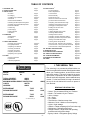
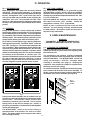
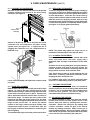
Quality Refrigeration
OWNER’S MANUAL
Instructions for the installation, operation
and maintenance of all Traulsen:
R & A Series Reach-In & Roll-In Refrigerators
R & A Series Pass-Thru & Roll-Thru Refrigerators
R & A Series Reach-In & Roll-In Freezers
R & A Series Reach-In Refrigerator/Freezers
R & A Series Reach-In & Roll-In Hot Food Cabinets
R & A Series Pass-Thru & Roll-Thru Hot Food Cabinets
This Traulsen unit is built to our highest quality standards. We build our refrigerators, freezers and heated
cabinets this way as a matter of pride. This philosophy has made Traulsen the leader in commercial
refrigeration since 1938. We thank you for your choice and confidence in Traulsen equipment and we know
you will receive many years of utility from this equipment.
All Traulsen units are placed on a permanent record file with the service department. In the event of any
future questions you may have, please refer to the model and serial number found on the name tag affixed
to the unit. Should you need service, however, call us on our toll free number, 800-825-8220 between 7:30
am and 4:30 pm CST, Monday thru Friday. It is our pleasure to help and assist you in every possible way.
INSTALLER
COMPLETE THE FOLLOWING INFORMATION PRIOR TO UNIT INSTALLATION
INITIAL START DATE:
SERIAL NO.
MODEL TYPE:
COMPANY/INDIVIDUAL NAME:
INSTALLER:
FORM NUMBER TR35743 REV. 10/04
P/N 375-60176-00
TABLE OF CONTENTS
I. THE SERIAL TAG
II. RECEIPT INSPECTION
III. INSTALLATION
a-Location
b-Packaging
c-Installing Legs or Casters
d-Shelf Pins
e-Roll-In Model Installation
f-Attaching Double Depth Units Together
g-Installing The Condensate Evaporator
h-Remote Installation
i-Cord & Plug
j-Power Supply
k-Wiring Diagram
l-Clearance
IV. OPERATION
a-Refrigerators
b-Freezers
c-Hot Food Cabinets
V. CARE & MAINTENANCE
a-Cleaning The Condenser
b-Hinge Replacement
c-Replacing The Gaskets
d-Cleaning The Exterior
e-Cleaning The Interior
f-Adjusting The Shelves
g-Replacing The Light Bulb
VI. OTHER
a-Service Information
b-Spare Parts
c-Warranty Registration
VII. INTELA-TRAUL®
a-Control Features
b-Alarm Explanations
c-Control Panel
d-Parts Assembly
e-Notes To The User
f-Enter The Customer Access Code
g-Customer Service Parameters
h-Adjusting Thermostat Set Point High
i-Adjusting Thermostat Set Point Low
j-Changing The Temperature Scale
k-Setting The 24-Hour Clock
l-Setting The Date
m-Setting Daylight Savings Time
n-Starting A Manual Defrost
o-Setting Defrost Lockouts
p-Adjusting The Door Perimeter Heaters
q-Adjusting The Room Temperature Offset
r-Setting The Audible Alarm Style
s-Viewing Sensor Temperatures
t-Hot Food Units - Adjusting The Thermostat
u-Hot Food Units - Turning The Unit OFF & ON
v-Hot Food Units - Temperature Adjustment
VIII. TROUBLE SHOOTING GUIDE
XI. SPARE PARTS LIST
XII. STAINLESS STEEL OVERVIEW
XIII. CARE OF STAINLESS STEEL
XIV. CORROSION REMEDIES
XV. WARRANTY INFORMATION
XVI. INDEX
Page 1
Page 2
Page 2
Page 2
Page 2-3
Page 3
Page 3
Page 3
Page 3-4
Page 4
Page 4
Page 4
Page 4
Page 4
Page 5
Page 5
Page 5
Page 5-6
Page 6
Page 6
Page 6
Page 6
Page 6
Page 7
Page 7
Page 7
Page 7
Page 8
Page 9
Page 10
Page 10
Page 11
Page 11
Page 12
Page 12
Page 13
Page 13
Page 14
Page 15
Page 15
Page 16
Page 17
Page 18
Page 18
Page 19
Page 19
Page 20
Page 20
Page 20
Page 21
Page 22
Page 23
Page 23-24
Page 24
Page 25
Page 26
I. THE SERIAL TAG
FORT WORTH, TX.
SERIAL
VOLTS
MODEL
Hz
PH
TOTAL CURRENT
AMPS
MINIMUM CIRCUIT
AMPS
MAXIMUM OVERCURRENT PROTECTION
LIGHTS
WATTS
HEATERS
AMPS
AMPS
REFRIGERANT
DESIGN PRESSURE
TYPE
HIGH
OZ
LOW
REFRIGERANT
DESIGN PRESSURE
TYPE
HIGH
OZ
LOW
370-60294-00 REV (A)
-1-
The serial tag is a permanently affixed sticker on
which is recorded vital electrical and refrigeration data
about your Traulsen product, as well as the model
and serial number. This tag is located in the upper
right interior compartment on all reach-in/pass-thru
and roll-in/roll-thru refrigerator, freezer and dual-temp
models. For hot food models, this tag is located on
the top of the unit behind the louvers to protect it
from the heat.
READING THE SERIAL TAG
• Serial = The permanent ID# of your Traulsen
• Model = The model # of your Traulsen
• Volts = Voltage
• Hz = Cycle
• PH = Phase
• Total Current = Maximum amp draw
• Minimum Circuit = Minimum circuit ampacity
• Lights = Light wattage
• Heaters = Heater amperage (Hot Food units only)
• Refrigerant = Refrigerant type used
• Design Pressure = High & low side operating
pressures and refrigerant charge
• Agency Labels = Designates agency listings
II. RECEIPT INSPECTION
III. INSTALLATION (continued)
All Traulsen products are factory tested for performance
and are free from defects when shipped. The utmost
care has been taken in crating this product to protect
against damage in transit. All interior fittings have been
carefully secured and the legs or casters are boxed and
strapped inside to prevent damage. Door keys will be
attached to the handle with a nylon strip. The handle is
protected by an easily removable nylon netting.
III. b - PACKAGING (cont’d):
WARNING: Read and review these instructions, in their
entirety, BEFORE attempting to disassemble and remove
the interior bracing. If either of the diagonal or upper
ceiling braces are dropped, they could cause personal
injury or damage to the equipment.
You should carefully inspect your Traulsen unit for
damage during delivery. If damage is detected, you
should save all the crating materials and make note on
the carrier’s Bill Of Lading describing this. A freight claim
should be filed immediately. If damage is subsequently
noted during or immediately after installation, contact
the respective carrier and file a freight claim. Under no
condition may a damaged unit be returned to Traulsen.
without first obtaining written permission (return
authorization).
To disassemble the bracing, first open the doors and
carefully remove the banding that holds the two
diagonal braces together.
WARNING: The diagonal braces will now be loose and
can fall out of position and possibly permit the ceiling
corner brace to fall.
Carefull remove one diagonal brace while supporting the
ceiling corner brace, so that it does not fall (see figure
1). Next, remove the ceiling brace, the remaining
diagonal brace, and lastly the floor brace - then discard.
Repeat as necessary for each section of the unit.
III. INSTALLATION
III. a - LOCATION:
Select a proper location for your Traulsen unit, away from
extreme heat or cold. Allow enough clearance between
the unit and the side wall in order to make use of the
door stay open feature at 120° (self-closing feature
operates up to 90°). The door(s) must be able to open a
minimum of 90° in order to make use of the maximum
clear door width available.
III. b - PACKAGING:
All Traulsen units are shipped from the factory bolted to
a sturdy wooden pallet and packaged in a durable
cardboard container. The carton is attached to the
wooden skid with the use of large staples. These should
first be removed to avoid scratching the unit when
lifting off the crate.
Most exterior stainless steel surfaces have a protective
vinyl covering to prevent scratching during
manufacturing, shipping and installation. After the unit
is installed in place of service, remove and discard the
covering from all surfaces.
To remove the wooden pallet, first if at all possible, we
suggest that the cabinet remain bolted to the pallet
during all transportation to the point of final installation.
The bolts can then be removed with a 3/4” socket
wrench. Avoid laying the unit on its front, side or back
for removal of the pallet.
Fig. 1
III. c - INSTALLING LEGS OR CASTERS:
6” high stainless steel legs are supplied standard for all
Traulsen reach-in and pass-thru units. Casters in lieu
of legs are available as an optional accessory for the
same models. These are shipped from the factory
packed inside a cardboard box which is strapped to one
of the shelves. Remove the nylon strap and open the
box, it should contain either four (4) legs or four (4)
casters and sixteen (16) bolts.
WARNING: THE CABINET MUST BE BLOCKED AND
STABLE BEFORE INSTALLING LEGS OR CASTERS.
To install the legs or casters, first raise and block the
reach-in a minimum of 7” from the floor.
For
installing legs, thread the legs into the threaded holes
NOTE: Traulsen does not recommend laying the unit
on the bottom of the cabinet (see figure 2). Be certain
down on its front, side or back. However, if you must
that all legs are tightly secured (legs and casters should
please be certain to allow the unit to remain in an
be tightened to 300 inch/pounds, max). When the unit
upright position afterwards for 24 hours before plugging
is set in its final position, it is important for proper opit in so that the compressor oils and refrigerant may
eration that the unit be level. The legs are adjustable for
settle.
this purpose, turn the bottom of the leg counterclockwise to raise it, clockwise to lower it. Level the
Roll-Thru models also include special interior wood
unit from front to back as well as side to side in this
bracing, intended to protect the cabinet during shipment.
manner, using a level placed in the bottom of the
This bracing should under no circumstances be removed
-2- cabinet.
prior to the unit being installed in its final location.
III. INSTALLATION (continued)
III. e - ROLL-IN MODEL INSTALLATION (cont’d):
facilitate rolling in racks. It is shipped wrapped in brown
paper and secured to the rack guides inside the
cabinet. To secure it in place, remove the two thumb
screws in the breaker strip near the bottom door
opening. Next, loosen the thumb screws located along
the floor at the threshold. Place the ramp(s) on top of
the loosened thumb screws and secure tabs on each
end to breaker strips with thumb screws previously
removed. After installing the ramp(s), it too should be
sealed to the floor.
III. c - INSTALLING LEGS OR CASTERS (cont’d):
Fig. 2
Please note that Traulsen units are not designed to be
moved while on legs. If the unit requires moving, a
pallet jack or forklift should be used to prevent damage.
For installing casters, the casters are “plate” type, and
require the use of four (4) bolts each to secure them
firmly to the cabinet bottom at each corner (see figure
3). The caster bolts are tightened using a 1/2” socket
wrench.
Bumper strips are secured to the back of Roll-In models
with thumb screws. Loosen these and make them
finger tight to conform with the requirements of the
National Sanitation Foundation (NSF).
III. f - ATTACHING DOUBLE DEPTH UNITS TOGETHER:
Double depth roll-in/roll-thru units are shipped as two
separate components which must be attached together
at the jobsite. To accomplish this, first, place the front
and rear cabinets in close proximity to each other being
careful to align the drain from the front of the rear unit
to the drain of the front unit. It will be necessary to level
both units together at this time.
Threaded Holes
Fig. 3
Next, using two pipe clamps, pull the units together (see
figure 5). Install the covers over the gap formed between
the units From inside the cabinets, using the screws
provided, install the breaker strips using the strip as a
template.
Caster
III. d - SHELF PINS:
The unit is supplied with shelves and shelf pins installed.
Check all shelf pins to assure they are tightened down
as they may have come loose during shipping. Rotate
the pins clockwise until they are secured against the
side of the cabinet.
Fig. 5 - Using two pipe
clamps, pull the two
units together and using
the screws provided.
Align the breaker strips
as a template for the
screw pattern inside and
outside the cabinet.
III. e - ROLL-IN MODEL INSTALLATION:
Roll-In cabinets set on the floor require the floor area to
be flat and level. In addition, after the cabinet is set in
place, sealant should be used around the perimeter of
the base to comply with National Sanitation Foundation
requirements (see figure 4). After sealing the unit, the
enclosed ramp should then be installed.
SEALING BASE OF ROLL-IN MODELS
III. g - INSTALLING THE CONDENSATE EVAPORATOR:
A condensate evaporator is normally supplied on all
self-contained models (remote models require provision
of either a floor drain or an optional electric condensate
evaporator). On those models supplied with a
top-mounted evaporator coil compartment, the
condensate evaporator is also secured to the top of the
cabinet. Check that the condensate pan is properly
located underneath the drain tube.
A SEALANT MUST BE USED
AROUND THE PERIMETER OF THE
BASE OF CABINET AS SHOWN TO
FULLY COMPLY WITH SANITARY REQUIREMENTS.
A RECOMMENDED SEALANT IS
DOW CORNING SILASTIC RTV #732
Fig. 4
A stainless steel threshold ramp(s) is included to
-3-
III. INSTALLATION (continued)
III. h - REMOTE INSTALLATION (cont’d):
must be done in accordance with good practice and
local regulations. See section “III. g” for information
concerning condensate removal for remote models.
III. g - INSTALLING THE CONDENSATE EVAP (cont’d):
NOTE: Some models, such as single section dualtemperature refrigerator/freezers, are supplied with a
bottom-mounted electric condensate evaporator. This
is shipped in a cardboard carton secured to the cabinet
interior, and must be PROPERLY installed prior to use
(see instructions supplied with the condensate
evaporator).
III. i - CORD & PLUG:
Most self-contained models are supplied with a cord &
plug attached. It is shipped coiled at the top of the
cabinet, secured by a nylon strip. For your safety and
protection, all units supplied with a cord and plug
include a special three-prong grounding plug on the
service cord. Select only a dedicated electrical outlet with
grounding plug for power source. NOTE: Do not under
any circumstances, cut or remove the round grounding
prong from the plug, or use an extension cord.
After the cabinet has been uncrated and the legs/
casters attached, you must install the bottom-mounted
electric condensate evaporator. Locate the four (4) holes
on the exterior bottom towards the rear of the cabinet.
Then, using the four (4) plastic push pins provided, attach the mounting rails to the cabinet bottom (the end
flange is to be up and be facing towards the cabinet rear).
Next, place the heater into the heater bracket (note the
enclosed springs are only to be used when the heater is
placed on the floor). Slide heater and bracket into the
mounting rails. Plug the supplied cord into both the
heater on one end, and the electrical outlet provided on
the cabinet exterior bottom towards the front (see
figure 6). Screw the “U-Trap” on to the drain line
located on the rear of the cabinet and then screw the
drain extension into the “U-Trap.”
III. j - POWER SUPPLY:
The supply voltage should be checked prior to
connection to be certain that proper voltage for the
cabinet wiring is available (refer to the serial tag to
determine correct unit voltage). Make connections in
accordance with local electrical codes. Use qualified
electricians.
Use of a separate, dedicated circuit is required. Size
wiring to handle indicated load and provide necessary
overcurrent protector in circuit (see amperage
requirements on the unit’s serial tag).
III. k - WIRING DIAGRAM:
Refer to the wiring diagram for any service work
performed on the unit. Should you require one, please
contact Traulsen Service at (800) 825-8220, and provide
the model and serial number of the unit involved.
III. l - CLEARANCE:
In order to assure optimum performance, the
condensing unit of your Traulsen unit MUST have an
adequate supply of air for cooling purposes. Therefore,
the operating location must either have a minimum of
12” clearance overhead of the condensing unit or allow
for unrestricted air flow at the back of the unit.
Clearance of at least 12” above is required in order to
perform certain maintenance tasks.
Fig. 6
NOTE: The use of the “U-TRAP” supplied is required.
Failure to use this component may allow cold air to
migrate down the drain line, resulting in condensation
on the rear of the cabinet.
A remote model is normally supplied configured for
condensate to be run to a floor drain unless purchased
with a condensate evaporator. The installer is
responsible for making the required extension to the
floor drain in accordance with good practice and local
regulations.
III. h - REMOTE INSTALLATION:
Remote models are supplied without compressors,
solenoid valves, etc. The correct voltage, amp listing
and refrigerant are listed on the units serial tag. It is the
responsibility of the installer to specify and supply the
correct size compressor(s) based upon this information
and on-site requirements. Refrigerant line installation
-4-
IV. OPERATION
IV. a - REFRIGERATORS:
Both refrigerators and freezers do not require manual
defrosting. During normal operation, a refrigerator
continuosly circulates above freezing cabinet air through
the coil. A compressor “OFF” cycle occurs every hour to
melt any frost which may accumulate on the coil during the
compressor “ON” cycle. The control will read “dEF” when
this occurs. With standard holding refrigerators, high relative
humidity is also maintained to prevent dehydration of stored
product.
IV. b - FREEZERS:
During normal operation, a freezer continuously circulates
below freezing cabinet air through the coil. The coil requires a
periodic defrosting for proper operation. This is accomplished
by an automatic, time activated, temperature/time terminated,
defrost program. The controller is preset at the factory for six
equally spaced defrost cycles within each 24-hour period.
At the start of a freezer defrost cycle, both the compressor
and evaporator fans are OFF. The INTELA-TRAUL® control will
read “dEF” (see figure 7). The electric heater (attached to the
coil) is energized. When a temperature device affixed to the
coil senses 70°F (models with electric defrost), the coil is fully
defrosted and the compressor operation is resumed, defrost
heaters are automatically turned off. The coil fans are delayed
from starting at the termination of a defrost cycle. Fan
operation is automatically resumed, or they can also be started
by a time or temp delay (whichever comes first). In case of
temp delay, it uses the same coil sensor and starts at 32°F.
The total refrigeration system operation is then resumed.
INTELA-TRAUL
°F
INTELA-TRAUL
°C
°F
SET
°C
IV. c- HOT FOOD CABINETS:
Hot food cabinet operation is governed by the
INTELA-TRAUL control, which controls the ON/OFF
operation of the strip heaters. The control can bet set to
maintain any operational temperature between 120 - 180°
F (in 5°F increments).
Hot food cabinets are delivered from the factory with
the control set to the “OFF” position. Follow the
instructions in section “VII. t” to get started.
NOTE: A vent is included at the top of all hot food
cabinets. The vent opening is factory set and secured
for best position. Be certain to make sure this vent is
kept free of any obstruction.
V. CARE & MAINTENANCE
WARNING
DISCONNECT ELECTRICAL POWER SUPPLY
BEFORE CLEANING ANY PARTS OF THE UNIT
V. a - CLEANING THE CONDENSER:
The most important thing you can do to insure a long,
reliable service life for your Traulsen is to regularly clean
the condenser coil.
The condensing unit requires regularly scheduled
cleaning to keep the finned condenser clean of lint and
dust accummulation. The INTELA-TRAUL control will
notify you through a “CLN-FIL” message when
cleaning is necessary (see page 8). Keeping the
condenser clean allows the cabinet to operate more
efficiently and use less energy.
To clean the condenser, first disconnect electrical power
to the cabinet and lift up the front louver assembly. To
lift this, remove the two screws located on both sides at
the bottom of the louver assembly (see figure 8).
SET
)
)
))
))
REFRIGERATOR
FREEZER
FREEZER
Fig. 7
During freezer defrost operation, heat is confined to the coil
enclosure to prevent any significant rise in temperature within
the food zone. The fan delay controls function upon
termination of a defrost cycle is two-fold. First, to prevent
blowing warm air into the food storage area. Second, to
prevent any condensation on the defrost coil from being blown
into the food storage area.
The INTELA-TRAUL ® control is set from the factory to
terminate defrost at 20 minutes in the event of a sensor
failure. This setting should never be tampered with, without
first consulting the factory.
-5-
Fig. 8
Remove
Screws
V. CARE & MAINTENANCE (cont’d)
V. a - CLEANING THE CONDENSER:
Once the screws are removed, the panel can be pivoted
upwards allowing full access to the front facing
condenser (see figure 9).
V. c - REPLACING THE GASKETS:
To remove the gasket to be replaced, grasp it firmly by
one corner and pull it out. Before attempting to install a
new gasket, both the unit and the gasket itself must be
at room temperature. Insert the four corners first by
using a rubber mallet (or hammer with a block of wood).
After the corners are properly inserted, work your way
towards the center from both ends by gently hitting with
a mallet until the gasket is completely seated in place
(see figure 11 for proper gasket placement).
Fig. 7
Lift-Up Louver
Assembly
Fig. 11
Vacuum or brush any dirt, lint or dust from the finned
condenser coil, the compressor and other cooling
system parts (see figure 10). If significant dirt is
clogging the condenser fins, use compressed air to
blow this clear.
NOTE: The gasket may appear too large, but if it is
installed as indicated above it will slip into place.
V. d - CLEANING THE EXTERIOR:
Exterior stainless steel should be cleaned with warm
water, mild soap and a soft cloth. Apply with a
dampened cloth and wipe in the direction of the metal
grain.
Fig. 10
Avoid the use of strong detergents and gritty, abrasive
cleaners as they may tend to mar and scratch the
surface. Do NOT use cleansers containing chlorine, this
may promote corrosion of the stainless steel.
Care should also be taken to avoid splashing the unit
with water, containing chlorinated cleansers, when
mopping the floor around the unit.
Condenser
Surface
For stubborn odor spills, use baking soda and water
(mixed to a 1 TBSP baking soda to 1 pint water ratio).
Lower louver assembly and replace the screws to hold
it in place.
V. e - CLEANING THE INTERIOR:
For cleaning both stainless steel and anodized
aluminum interiors, the use of baking soda as described
in section “V. d” is recommended. Use on breaker strips
as well as door gaskets. All interior fittings are
removable without tools to facilitate cleaning.
V. b - HINGE REPLACEMENT:
Both the door and hinge can be easily removed from the
cabinet. To remove the door, remove the plug at the
bottom of the top hinge. Inside the hinge there is a small
screw which secures the door in place. Remove this
with a flat head screwdriver and the door can then be
lifted off the hinge. To remove the door portion of the
hinge from the door, lift off the hinge cover and then
remove the three Phillips head screws which secure the
hinge in place on the door. To remove the cabinet
portion of the hinge, remove the three Phillips head
screws which hold it in place. On solid door units, the
top hinge(s) contains a microswitch for controlling the
interior lighting.
V. f - ADJUSTING THE SHELVES:
For shelves mounted on pins, first select the desired
location and remove the white plastic covers in the
interior back and sides by rotating them counterclockwise. Remove the shelf pins by rotating them
counter- clockwise. Install the pins in the desired
location by rotating clockwise. Make sure the pin is
securely tightened down. Do not over tighten. Slide the
shelf into its new position, and replace the white plastic
covers into the holes vacated by the shelf pins.
To reassemble the hinge reverse the previous procedure.
-6-
V. CARE & MAINTENANCE (cont’d)
VI. OTHER
V. g - REPLACING THE LIGHT BULB:
All Traulsen R & A Series models are supplied with
incandecent lighting unless optional fluorescent
lighting was ordered (except for sliding glass door
models for which fluorescent lights are supplied
standard).
VI. a - SERVICE INFORMATION:
Before calling for service, please check the following:
Is the electrical cord plugged in?
Is the fuse OK or circuit breaker on?
The bulb is a 115 volt/40 watt, T-6 ⁄2 intermediate clear
refrigerator lamp. It is mounted at the top front of the
cabinet at the center, and is located behind a plastic light
cover on refrigerator and freezer model.
1
Is the power switch “ON”?
If after checking the above items and the unit is still not
operating properly, please contact an authorized
Traulsen service agent. A complete list of authorized
service agents was provided along with your Traulsen
unit. If you cannot locate this, you may also obtain the
name of a service agent from the Service/Contact page
of our website: www.traulsen.com.
Heated units (RHF/AHF/RIH/AIH/RDH/ADH/RIDH/AIDH)
are equipped with a similar type bulb, however this is
shatterproof because these models do not include a
plastic light cover.
To replace the bulb, first remove the light cover (if so
equipped). This can be accomplished by squeezing it
together on both sides until it comes free. Replace the
light bulb, then squeeze both sides of the light cover
together and replace in its original position.
If service is not satisfactory, please contact our in-house
service department at:
Traulsen
4401 Blue Mound Road
Fort Worth, TX 76106
(800) 825-8220
Traulsen reserves the right to change specifications or
discontinue models without notice.
VI. b - SPARE PARTS:
Spare or replacement parts may be obtained through a
parts supplier or one of our authorized service agents.
A complete list of authorized service agents
accompanies this manual and is also posted on our
company’s official website @ www.traulsen.com.
VI. c - WARRANTY REGISTRATION:
For your convenience, the warranties on your new
Traulsen unit may be registered with us by one of two
methods. Completing the enclosed warranty card
(shipped with the unit).
-7-
VII. The INTELA-TRAUL® Control System
Your new Traulsen Refrigerator, Freezer or Hot Food cabinet is equipped with a state-of-theart electronic microprocessor INTELA-TRAUL® control, which precisely regulates operation
and provides alarms when problems occur. It is supplied from the factory completely ready
for use and requires no adjustment (except Hot Food units which are set in the “OFF”
position, see page for 20 for more info), but without the audible alarms activated. See pages
9 thru 20 for more information.
VII. a - INTELA-TRAUL® CONTROL FEATURES:
1- Internal Time Clock
• Eliminates defrost time clock (refrigerator and freezer models only).
• Defrost cycle can be quickly adjusted to suit individual location and use.
• Must be set at power-up and reset after a power failure.
• Will automatically update for Daylight Savings Time.
2- Water Resistant Housing - The face of the control is water resistant to provide for protection during cleaning.
3- Parameter/Service Levels
• See “Customer / Service Parameters” on Page 11.
4- Defrost Lockouts - See “Setting Defrost Lockouts” on page 17 (refrigerator and freezer models only).
• Customers can set up to 4 different defrost lockout periods. The lockout prevents the unit from going into a defrost cycle
during peak kitchen use. Note: The 24-hour clock must be set for this feature to operate correctly.
5- Data Storage - The control comes equipped with 72 hours worth of data storage capability including:
• Records cabinet air temperatures every 6 minutes, needed to document “Due Diligence” in accordance with HAACP
standards.
• Records alarm events.
• Records diagnostic test of each sensor every 24 hours.
• Records failed security attempts.
• Records door open cycles.
• Records defrost cycles (refrigerator and freezer models only).
Note: The 24-hour clock and the date must be set for the above information to be recorded at the
correct time and date.
6- Communication Ability - An RS485 port port is available as a means of retrieving information from the stored data.
7- Anti-Condensate Door Perimeter Heater Control (refrigerator and freezer models only)
“No-Sweat” feature is an energy savings system that allows the customer to set the percent on time for the door heater as
needed for the prevailing ambient conditions. It is used to prevent condensation from forming around the perimeter of the
doors.
8- Alarms (See the following pages for explanations)
• High Cabinet Air Temperature
• System Leak (refrigerator, freezer & dual-temp models only)*
• Low Cabinet Air Temperature
• Door Open**
• Loss Of Power
• Clean Condenser (refrigerator and freezer models only)*
• Sensor Failure
* Not Available On Remote Models
** Not Available On Fire-Rated Or Sliding Glass Door Models
-8-
VII. INTELA-TRAUL® (continued)
VII. a - ALARM EXPLANATIONS:
*NOTE: Explanation of alarms assume the audible alarm style is set at a 3-second burst or a
continuous audible alarm. References to the audible alarm do not apply if the audible alarm
style is set to OFF (Refer to page 19 for setting the audible alarm style).
High Cabinet Air Temperature: The audible alarm* will sound and the display will read HI
CAb when the temperature inside the cabinet rises above a pre-programmed limit. The limit is
determined by the type of unit being operated (i.e.: refrigerator/freezer). To turn off the audible
alarm*, press the alarm cancel button. The visual alarm text will continue to display until the
cabinet air temperature falls below the limit. If the temperature does not fall below the limit
within 5 minutes, the audible alarm* will sound again and an additional Call Service message
will display.
POSSIBLE CAUSES (for Refrigerator & Freezer Models):
• Doors open for extended periods of time.
• Large amounts of hot product placed inside the cabinet.
• Condenser coil dirty.
Low Cabinet Air Temperature: The audible alarm* will sound and the display will read Lo
CAb when the temperature inside the cabinet falls below a pre-programmed limit. The limit is
determined by the type of unit being operated (i.e.: refrigerator/ freezer). To turn off the audible
alarm*, press the alarm cancel button. The visual alarm text will continue to display until the
cabinet air temperature rises above the limit. If the temperature does not rise above the limit
within 5 minutes, the audible alarm* will sound again and an additional Call Service message
will display.
POSSIBLE CAUSES (for Refrigerator & Freezer Models):
• No product in unit.
• Failed sensors.
Loss Of Power: The audible alarm* will sound and the display will read Electrical Loss, when
the unit regains power after an outage. To turn off the audible alarm* and/or clear the visual
text, press the alarm cancel button. You must reset the clock and date if you are using any
defrost lockouts or are retrieving the information from the data storage memory. See “Setting
The 24-Hour Clock” page 12 and “Setting the Date” page 15.
Door Open: The door open icon on the face of the control will light and the display will read
Door Open, after the door or doors have been open for 2 minutes. If the door remains open for
an additional 13 minutes the audible alarm* will sound. To turn off the alarm, close the door or
press the alarm cancel button. If the door remains open for an additional 5 minutes, the audible
alarm* will sound again (n/a on fire-rated and sliding glass door models).
System Leak: The audible alarm* will sound and the display will read Call Service, when the
control detects a leak in the refrigeration system. To turn off the audible alarm*, press the alarm
cancel button. The visual alarm text will remain until a service technician has repaired the unit.
If the condition remains for 24 hours, the audible alarm* will sound again.
POSSIBLE CAUSES:
• Low refrigerant charge.
• Discharge sensor has failed low.
CONDENSERCLEAN™: The audible alarm* will sound and the display will read Clean
Filter, when the operating pressures and temperatures exceed a safe operating range. As the
load on the condenser decreases, the alarm will turn off by itself. As the pressures on the
condenser continues to rise, the audible alarm* will stay on for longer periods of time. To turn
off the audible alarm*, press the alarm cancel button. The visual alarm text will remain until the
filter/condenser has been cleaned. If the condition remains for 24 hours, the audible alarm* will
sound again and visual display will read Call Service.
POSSIBLE CAUSES:
• Inadequate air flow through condenser unit.
• Discharge sensor has failed high.
Sensor Failures: The audible alarm* will sound and the display will read Sensor Failure Call
Service, when any of the unit sensors fail to operate. To turn off the audible alarm*, press the
alarm cancel button. The visual alarm text will remain until the sensor has been replaced.
Depending on the function of the sensor, the audible alarm* will sound again in either 5 minutes
or 24 hours.
*Not available on remote models.
-9-
VII. INTELA-TRAUL® (continued)
VII. c - CONTROL PANEL:
LED FOR ° F
LED FOR °C
INTELA-TRAUL
°F
3-DIGIT (RED)
LED DISPLAY
°C
SET
DOOR OPEN ICON
W / LED
)
))
ALARM CANCEL
BUTTON
IRDA - INFRA RED
DATA AQUISITION
DEFROST ICON
W / LED
FREEZER
VII. d - PARTS ASSEMBLY: (Reach-In & Roll-In Cabinets)
COIL SENSOR*
337-60071-00
(refrigerator & freezer only)
CABINET SENSOR*
337-60069-00
RH SENSOR*(refrigerator & freezer only)
337-60080-00
DISCHARGE SENSOR*
337-60072-00
(refrigerator & freezer only)
HORN*
337-60070-00
HOLDER CLIP*
377-60038-00
INTELA-TRAUL®**
VERTICAL CONTROLLER
337-60090-00
337-60091-00
337-60092-00
337-60098-00 (Hot Food Units)
INCLUDES ALL SHOWN
HORN
DEFROST COMPRESSOR
RELAY POWER LINE IN 2
(refrigerator & freezer only)
DOOR HEATER
EVAP BLOWER RELAY
POWER IN LINE 1
TRANSFORMER RS485
DOOR RELAY
CABINET AIR
DISCHARGE LINE
(refrigerator & freezer only)
HOLDER CLIP
EVAP COIL (refrigerator & freezer only)
RH / EXTERNAL AIR (refrigerator & freezer only)
-10-
*= Can be ordered seperately
**=Requires unit Model No. & S/N to place order.
VII. INTELA-TRAUL® (continued)
VII. e - NOTES TO THE USER:
You only have 20-30 seconds between button pushes. If you take longer than 30 seconds, the controller will revert back to
displaying the cabinet temperature. If you enter the wrong security code, the controller will revert back to displaying the
cabinet temperature. You can exit the parameters at any time by pressing the alarm cancel button or by waiting 20-30
seconds.
VII. f - ENTER THE CUSTOMER ACCESS: This is required to set any of the control parameters
Use the security code 0, A, 1
Press the set button SET .
and the following instructions:
The display will read
Customer/Service Access.
Press the set button SET .
The display will show three zeros with the left zero flashing
Press the set button SET .
The display will show three zeros with the center zero flashing
Press the down arrow key
to sequence through F, E, d, C, b, A, 9, 8, 7,…etc.
When you reach A press set SET .
The display will show zero, A, zero with the right zero flashing
Press the up arrow key
to sequence through 1, 2, 3, 4, 5, 6, 7, 8, 9, A, b,…etc.
When you reach 1 press set SET .
The display will read
.
Thermostat Set Point High.
You are now in the CUSTOMER / SERVICE PARAMETERS.
-11-
VII. INTELA-TRAUL® (continued)
VII. g - CUSTOMER SERVICE PARAMETERS:
Listed below are the available parameters in the order they appear, using the down arrow key on the
controller. You can use either the up or down arrow keys to scroll through the options.
Thermostat Set Point High*
Defrost Lockout 2
Thermostat Set Point Low
Defrost Lockout 3
Temperature Scale*
Defrost Lockout 4
Audible Alarm Style*
Dew Point Compensation Factor*
Time (24-hour clock)*
Room Temperature Offset
Date (month - day - year)*
Evaporator Coil Sensor
Daylight Savings *
Discharge Line Sensor
Defrost Lockout 1
Start Manual Defrost
*Available on Hot Food units.
VII. h - ADJUSTING THE THERMOSTAT SET POINT HIGH:
This parameter sets the high point of the desired cabinet temperature range. Typically, freezers will
range from -3° F to 0° F (-19° C to -18° C) and refrigerators will range from 36° F to 40° F (2° C to 4° C)
for this parameter setting. This parameter is preset at the factory and does not have to be adjusted
unless the customer chooses to do so. Note: Set Point Low and Set Point High cannot be set to the
same temperature. There will be at least 1-2 degree difference between the two settings.
Follow the instructions to enter the customer access code on page 11. When the control
display reads
Thermostat Set Point High. Press the set button SET .
Use the arrow keys
to adjust the temperature to your desired setting.
When the display shows the temperature you want press the set button SET .
The display will then read
Thermostat Set Point High.
You can use the up or down arrow keys to scroll to the next parameter
or press the alarm cancel button to exit
) .
))
-12-
VII. INTELA-TRAUL® (continued)
VII. i - ADJUSTING THE THERMOSTAT SET POINT LOW:
This parameter sets the low point of the desired cabinet temperature range. Typically, freezers will range
from -6° F to -4° F (-21° C to -20° C) and refrigerators will range from 32° F to 34° F ( 0° C to 1° C) for this
parameter setting. This parameter is preset at the factory and does not have to be adjusted unless the
customer chooses to do so. Note: Set Point Low and Set Point High cannot be set to the same temperature. There will be at least 1-2 degree difference between the two settings.
Follow the instructions to enter the customer access code on page 11. When the control
displays
Thermostat Set High, press the down arrow key
display reads
until the control
Thermostat Set Point Low. Press the set button SET .
Use the arrow keys
to adjust the temperature to your desired setting.
When the display shows the temperature you want press the set button SET .
The display will then read
Thermostat Set Point High.
You can use the up or down arrow keys to scroll to the next parameter
or press the alarm cancel button to exit
) .
))
VII. j - CHANGING THE TEMPERATURE SCALE:
The temperature scale determines if the temperature displayed will be in degrees
Fahrenheit or degrees Celsius.
Follow the instructions to enter the customer access code on page 11. When the control
displays
Thermostat Set High, press the down arrow key
display reads
Temperature Scale. Press the set button SET .
The display will start with the current setting either
or
until the control
for degrees Fahrenheit
for degrees Celsius. Use the arrow keys
to toggle between the options.
When the display shows the scale you want press the set button SET .
The display will then read
Thermostat Set Point High.
You can use the up or down arrow keys
or press the alarm cancel button to exit
to scroll to the next parameter
) .
))
-13-
VII. INTELA-TRAUL® (continued)
VII. k - SETTING THE 24-HOUR CLOCK:
The internal timeclock must be set in order for the data storage memory to correctly log events and to
allow any defrost lockout to occur at the correct time of day. If the clock is not set, the control assumes
the time is 12 a.m. at the time power is supplied to the unit. The hours on a 24-hour time clock read the
following way:
H01 = 1:00 a.m.
H02 = 2:00 a.m.
H03 = 3:00 a.m.
H04 = 4:00 a.m.
H05 = 5:00 a.m.
H06 = 6:00 a.m.
H07 = 7:00 a.m.
H08 = 8:00 a.m.
H09 = 9:00 a.m.
H10 = 10:00 a.m.
H11 = 11:00 a.m.
H12 = 12:00 p.m.
H13 = 1:00 p.m.
H14 = 2:00 p.m.
H15 = 3:00 p.m.
H16 = 4:00 p.m.
H17 = 5:00 p.m.
H18 = 6:00 p.m.
H19 = 7:00 p.m.
H20 = 8:00 p.m.
H21 = 9:00 p.m.
H22 = 10:00 p.m.
H23 = 11:00 p.m.
H24 = 12:00 a.m.
Follow the instructions to enter the customer access code on page 11. When the control
displays
Thermostat Set High, press the down arrow key
display reads
until the control
Clock. Press the set button SET .
The display will show
Hours. The right two numbers will be flashing.
Use the arrow keys
to set the hour.
When the correct hour is displayed, press the set button SET .
The display will show
Minutes. The right two numbers will be flashing.
Use the arrow keys to set the minutes
.
When the correct minutes are displayed, press the set button SET .
The display will then read
Thermostat Set Point High.
You can use the up or down arrow keys
or press the alarm cancel button to exit
to scroll to the next parameter
) .
))
-14-
VII. INTELA-TRAUL® (continued)
VII. l - SETTING THE DATE:
The date must be set in order for the data storage memory to correctly log events. Follow the instructions to enter the customer access code on page 11. When the control displays
Set Point High, press the down arrow key
until the control display reads
the set button SET . The display will show
Press the arrow keys
Thermostat
Date. Press
(year). The right two numbers will be flashing.
to set the year. When the correct year is displayed, press the set
button SET . The display will show
(month). The right two numbers will be flashing. Use
the arrow keys
When the correct month is displayed, press the set
button SET .
the arrow keys
SET
to set the month.
The display will show
to set the day.
. The display will then read
arrow keys
(day). The right two numbers will be flashing. Press
When the correct day is displayed, press the set button
Thermostat Set Point High. You can use the up or down
to scroll to the next parameter, press the alarm cancel button to exit
) .
))
VII. m - SETTING DAYLIGHT SAVINGS TIME:
This parameter is preset at the factory to automatically adjust the 24-hour clock for Daylight Savings
Time. Follow the instructions to enter the customer access code on page 11. When the control
displays
Thermostat Set Point High, press the down arrow key
until the display reads
Daylight Savings Time. Press the set button SET . The display will show
light Savings Time (Yes, automatically adjust for Daylight Savings Time).
button SET , for “NO” press the up or down arrow key
Daylight Savings Time (no). Press the set buttonSET
).
))
-15-
For “YES,” press the set
. The display will read
. The display will read
Set Point High. You can press the the up or down arrow keys
eter or press the alarm cancel button to exit
Day-
Thermostat
to scroll to the next param-
VII. INTELA-TRAUL® (continued)
VII. n - STARTING A MANUAL DEFROST CYCLE:
This parameter allows a service technician to start a defrost cycle at any time. This parameter
will override any lockout settings.
Follow the instructions to enter the customer access code on page 11. When the control
displays
Thermostat Set High, press the down arrow key
display reads
until the control
Start Manual Defrost.
Press the set button SET .
The display will show
(NO).
Press either arrow key
(YES).
The display will show
.
Press the set button SET .
The display will then read
Thermostat Set Point High.
You can use the up or down arrow keys
or press the alarm cancel button to exit
to scroll to the next parameter
) .
))
Reach-In/Roll-In Models
INTELA-TRAUL
°F
°C
The defrost icon will be lit,
SET
)
))
and the display will read
when the unit is
in defrost.
FREEZER
DEFROST ICON
NOTE: Traulsen refrigerator units also have an off-cycle defrost once an hour, at which time the
control will read
. This defrost is temperature terminated and can last from 3 - 10
minutes (dEF will be displayed for 22-27 minutes).
-16-
VII. INTELA-TRAUL® (continued)
VII. o - SETTING THE DEFROST LOCKOUTS:
The defrost lockout parameters allow the customer to prevent the unit from going into a defrost cycle for
two hours during a set timeframe. Customers can set up to four defrost lockout parameters. They are all
programmed the same way. The parameters will be set for the time the lockout is to start. The controller
automatically calculates 2 hours from that setting. The options are similar to the 24-hour clock settings
and are in 30-minute increments. Each of the lockout parameters covers 6 hours of the 24-hour clock.
Note: The 24-hour clock must be set for this feature to operate at the correct time of day. See “Setting
the 24-Hour Clock” on page 14.
Sample:
OFF
020 = 2:00 a.m.
023 = 2:30 a.m.
030 = 3:00 a.m.
033 = 3:30 a.m.
040 = 4:00 a.m.
043 = 4:30 a.m.
050 = 5:00 a.m.
053 = 5:30 a.m.
060 = 6:00 a.m.
063 = 6:30 a.m.
070 = 7:00 a.m.
073 = 7:30 a.m.
080 = 8:00 a.m.
OFF
080 = 8:00 a.m.
083 = 8:30 a.m.
090 = 9:00 a.m.
093 = 9:30 a.m.
100 = 10:00 a.m.
103 = 10:30 a.m.
110 = 11:00 a.m.
113 = 11:30 a.m.
120 = 12:00 p.m.
123 = 12:30 p.m.
130 = 1:00 p.m.
133 = 1:30 p.m.
140 = 2:00 p.m.
OFF
OFF
140 = 2:00 p.m.
200 = 8:00 p.m.
143 = 2:30 p.m.
203 = 8:30 p.m.
150 = 3:00 p.m.
210 = 9:00 p.m.
153 = 3:30 p.m.
213 = 9:30 p.m.
160 = 4:00 p.m.
220 = 10:00 p.m.
163 = 4:30 p.m.
223 = 10:30 p.m.
170 = 5:00 p.m.
230 = 11:00 p.m.
173 = 5:30 p.m.
233 = 11:30 p.m.
180 = 6:00 p.m.
240* = 12:00 a.m.
183 = 6:30 p.m.
243* = 12:30 a.m.
190 = 7:00 p.m.
010 = 1:00 a.m.
193 = 7:30 p.m.
013 = 1:30 a.m.
200 = 8:00 p.m.
020 = 2:00 a.m.
* Denotes not available.
A lockout cannot be programmed to start at 12:00 a.m. or 12:30 a.m. due to conflicts with other
internal programs. The defrost lockouts cannot be programmed to run back-to-back. For example, if
dL1 is set to 080, then a defrost cycle would be locked out from 8:00 a.m. to 10:00 a.m. Because of
the dL1 setting the dL2 parameter would not let the user choose a lockout start time before 10:30
a.m. All lockouts are preset at the factory to OFF.
Follow the instructions to enter the customer access code on page 11. When the control
displays
Thermostat Set High, press the down arrow key
control display reads
The display will show
or
Off. Press the arrow keys
until the control the
. Press the set button SET .
to set the start time.
When the correct time is displayed, press the set button SET .
The display will then read
Thermostat Set Point High.
You can press the up or down arrow keys
or press the alarm cancel button to exit
to scroll to the next parameter
) .
))
-17-
VII. INTELA-TRAUL® (continued)
VII. p - ADJUSTING THE DOOR PERIMETER HEATERS:
This parameter allows the customer to turn ON and OFF the anti-condensate door perimeter heaters.
This parameter is set to the highest setting (100) at the factory so that the door heaters stay on continuously. If you choose to have the door heaters cycle on and off, lower this parameter to approximately 30.
If condensation forms around the doors, increase the parameter until condensation stops. The exact
setting will vary depending on ambient conditions. This feature is not available on undercounter models.
Follow the instructions to enter the customer access code on page 11. When the control displays
Thermostat Set High, press the down arrow key
until the control display reads
DewPoint Compensation Factor. Press the set button SET . Press the arrow keys
to
adjust the factor to your desired setting. When the display shows the factor you want press the set
button SET . The display will then read
down arrow keys
Thermostat Set Point High. You can use the up or
to scroll to the next parameter or press the alarm cancel button to exit
) .
))
VII. q - ADJUSTING THE ROOM TEMPERATURE OFFSET:
The room temperature offset parameter allows a service technician or end user the ability to have the
display show a temperature that is within three degrees of the actual temperature being read by the
cabinet air sensor. This allows for continuity of reading between different temperature reading devices.
(i.e.: thermistor Vs thermocouple Vs handheld thermometer) This parameter is preset at the factory to
“0” or no offset.
Follow the instructions to enter the customer access code on page 11. When the control displays
Thermostat Set High, press the down arrow key
Room Temperature Offset. Press the set button SET .
until the control display reads
Use the arrow keys
to adjust the
offset to your desired setting. When the display shows the offset you want press the set button SET .
The display will then read
keys
Thermostat Set Point High. You can use the up or down arrow
to scroll to the next parameter or press the alarm cancel button to exit
-18-
) .
))
VII. INTELA-TRAUL® (continued)
VII. r - SETTING THE AUDIBLE ALARM STYLE:
This parameter will allow the customer to turn on/off the audible alarm feature on the
INTELA-TRAUL® control. The audible alarm is preset from the factory to OFF. The customer can choose
between an audible alarm that sounds for 3 seconds then automatically turns off, or a
continuous audible alarm that must be manually acknowledged. Regardless of this feature’s setting,
visual alarm text will display when conditions warrant.
To adjust this setting, follow the instructions to enter the customer access code on page 11. When
the control displays
Thermostat Set Point High, press the up arrow key
Audible Alarm Style. Press the set button SET . The display will read
play reads
OFF. Use the arrow keys
or
until the dis-
to scroll between
for the 3-Second Audible Alarm Burst
for Continuous Audible Alarm. When the display shows your choice of style, press the set
button SET . The display will then read
thermostat Set Point High. Use the arrow keys
to scroll to the next parameter or press the Alarm Cancel Button
) to exit.
))
VII. s - VIEWING SENSOR TEMPERATURES:
These parameters allow a service technician or customer to view the temperature of all sensors
within the unit. The temperatures cannot be adjusted.
Follow the instructions to enter the customer access code on page 11. When the control displays
Thermostat Set Point High
Evaporator Coil Sensor
, press the DOWN arrow key
or Disharge Line Sensor
The display will read Thermostat Set Point High
Press the UP or DOWN arrow keys
CANCEL button
unit the display reads
or press the SET button SET .
.
to scroll through the parameters or press the ALARM
) to exit.
))
-19-
VII. INTELA-TRAUL® (continued)
VII. t - HOT FOOD UNITS, ADJUSTING THE THERMOSTAT & TURNING THE UNIT OFF/ON:
This parameter sets the desired cabinet temperature.
Please note that hot food units are delivered
from the factory set to the OFF position.
Follow the instructions to enter the customer access code on page 11. When the control reads
Thermostat Set Point High, press the set button SET .
Use the arrow keys
to adjust the temperature to your desired setting. When the display
shows the temperature you want press the set button SET . The display will then read
Thermostat Set Point High. You can use the up or down
the next parameter or press the alarm cancel button
arrow keys to scroll to
to exit.
VII. u - HOT FOOD UNITS, TURNING THE UNIT OFF/ON:
After the temperature has been set, the customer can continuously turn the unit OFF and then back
ON to the same temperature. To turn the unit ON /OFF press the alarm cancel button
, (please
note that this feature is not available on versions of the control manufactured prior to September
2000), or if an alarm warning condition is present, use the alternative ON/OFF activation method.
To turn the unit ON/OFF using the alternative method, press both arrows
at the same time,
the set temperature will remain in memory.
VII. u - HOT FOOD UNITS, TEMPERATURE ADJUSTMENT:
Press the SET button SET and the UP ARROW button
at the same time. The display will
flash the current temperature setting or OFF (if the unit is turned off). Use the UP
ARROW
or DOWN
buttons to adjust your desired temperature setting (temperature range is 120° thru
180° F, and OFF) then press the SET button SET . The display will go back to reading cabinet
temperature. If OFF is selected. the display will then read OFF. NOTE: If you wish to change the
set temperature at anytime follow this procedure.
These models also include a “One-Time Temperature Setting Adjustment” feature. Upon start-up,
the unit will warm-up to the last temperature you had set for it, unless changed.
-20-
VIII. TROUBLE SHOOTING GUIDE
FIND YOUR PROBLEM HERE
REMEDY
1. Condensing unit fails to start.
a.
b.
Check if cord & plug has been disconnected.
Check INTELA-TRAUL® temperature setting.
2. Condensing unit operates for
prolonged periods or continuously.
a.
b.
c.
Are doors closing properly?
Dirty condenser or filter. Clean properly.
Evaporator coil iced. Needs to defrost. See
instructions for setting a manual defrost cycle
on page 16.
Shortage of refrigerant, call service.
d.
3. Food compartment is too warm.
a.
b.
Check door(s) and gasket(s) for proper seal
Perhaps a large quantity of warm food has
recently been added or the door was kept
open for a long period of time, in both
cases, allow adequate time for the cabinet
to recover its normal operating temperature.
INTELA-TRAUL® setting too high, readjust
per instructions on page 12.
c.
4. Food compartment is too cold.
a.
Perhaps a large quantity of very cold or frozen
food has recently been added. Allow adequate
time for the cabinet to recover its normal operating
temperature.
Adjust the INTELA-TRAUL® to a warmer
setting, see page 13.
b.
5. Condensation on the exterior surface.
a.
b.
Check door alignment and gaskets for proper seal.
Condensation on the exterior surface of the
unit is perfectly normal during periods of
high humidity. However, to alleviate the
condition, adjust the INTELA-TRAUL®
“Dewpoint Compensation Factor,” see page 18.
6. Compressor hums but does not start.
a.
Call for service.
-21-
XI. SPARE PARTS LIST
PART
PART #
DESCRIPTION
Bulb, Fluorescent
337-27690-00
Replacement bulb for fluorescent light models
Bulb, Incandescent
378-29776-00
Replacement bulb for incandescent light models
Bulb Cover
337-30858-00
Replacement bulb cover for incandescent light models
Caster, 6” High
344-13140-01
Optional caster for all reach-in models
Caster, 4” High W/O Brake
SMO-28627-00
Optional lower height caster
Caster, 4” High W/Brake
SMO-28628-00
Optional lower height caster
Caster Bolt (4 req’d per caster)
351-25542-00
Bolt for above
Door Handle, Stainless Steel
344-37690-00
Replacement handle for solid door units
Door Lock, Sliding Glass
346-60005-00
Jewelers type door lock for sliding glass door model
Hinge Cam
344-28488-00
Replacement hinge cam
Hinge Cover
344-28486-00
Replacement hinge cover
Hinge, Spring Assist
SER-29021-03
Alternative hinge, spring assist
Hinge Assembly W/Stop Feature
SER-40677-02
Alternative hinge, stop feature
Hinge Assembly
SER-28583-00
Replacement hinge assembly
Key, Master
346-29467-00
Replacement key for solid door units
Leg, 4” High Adjustable
344-29558-00
Replacement or optional leg
Leg, 6” High Adjustable
344-13168-01
Replacement leg
Shelf Pin
344-24759-00
Replacement shelf pin
Shelf Clip
344-08982-00
Replacement shelf clip for pilasters
Tray Slide, #4 Chrome Rod Type
340-04842-00
Tray slide for rim support of 18” x 26” pan
Tray Slide, Universal
719-07805-00
Tray slide for 18” x 26”, 14” x 18” or 12” x 20” pan
Tray Slide, #1
719-20236-00
Tray slide for 18” x 26” or 14” x 18” pan
-22-
XII. STAINLESS STEEL OVERVIEW
XII. a - INTRODUCTION:
All Traulsen R & A Series Refrigerator, Freezer, DualTemp and Heated Cabinet models are constructed with
a high quality 430 series, 20 gauge stainless steel
exterior finish (front, sides and doors). The interior
finish on these same R-Series models are constructed
using 300 series stainless steel (anodized aluminum is
used for A-Series).
XII. c - UNDERSTANDING THE CAUSES OF CORROSION:
should be cleaned up promptly to avoid possible stains
and corrosion.
XIII. CARE OF STAINLESS STEEL
XIII. a - USING THE PROPER TOOLS:
Use of proper cleaning materials will do much to
prolong the appearance of your Traulsen refrigeration
product. We particularly encourage the use of either
plastic scouring pads or soft cloths for cleaning
stainless steel.
The stainless steel finish on Traulsen R & A Series should
retain its appearance throughout the products usable
lifetime. However, some care is required to maintain this
appearance. The following paragraphs will provide a
guideline on proper care of the exterior/interior finish,
as well as some suggestions on how to repair a finish
which has been marred due to adverse environmental
conditions or improper jobsite care.
Soft nylon scouring pads can also be used, however care
has to used to insure that all scrubbing is done in the
direction of the metals “GRAIN.” Because metals are
chrystalline in nature, when they are in a solid state the
individual ions line up to form visible grain lines. Use of
a soft nylon scouring pad in a direction opposite of the
grain will mar its luster. Always do so “PARALLEL” to
the grain.
XII. b - STAINLESS STEEL, HOW IT WORKS:
The process by which stainless steel retains its
appearance is a result of its type of metal alloy. Steel is
a composite of metals combined in a specific industrial
process. Stainless steel contains a high percentage of
chromium, the addition of which provides both its
appearance, and a microscopic surface layer protecting
the steel underneath from corrosion. This external layer
acts as a barrier, preventing typical oxidation of the steel.
Remove this barrier, and the environment will
eventually corrode the metal, marring its appearance.
There are several types of tools which should NEVER
BE USED when cleaning stainless steel, these include:
•
•
•
•
WIRE BRUSHES
METAL SCOURING PADS
SANDPAPER
SCRAPERS & PUTTY KNIVES
Use of any of these tools will result in scratches or
removal of the stainless steel’s protective layer, which
will eventually lead to corrosion and rust.
XII. c - UNDERSTANDING THE CAUSES OF CORROSION:
Corrosion to stainless steel can only be caused in one
of four specific ways:
XIII. b - USING THE RIGHT CLEANSER:
Avoid all cleaning products containing chloride
ingredients. Use of a cleanser specifically designed for
stainless steel is highly recommended. You may find
yourself in a situation where you are uncertain if a
particular cleaning product contains any chlorides. If
unsure, its probably best to just assume that it does and
avoid its use in cleaning a Traulsen refrigeration
product.
1) ABRASION
Abrasion can be caused during routine cleaning of the
metal, either by use of an abrasive cleanser, or use of an
abrasive device, such as a metal scouring pad.
Abrasion can also be caused by contact with other hard
surfaces, such as nearby equipment, walls or tools.
Special care should be taken to position your unit
properly to prevent accidental dents and scratches.
2) WATER
Water everywhere contains various deposits, or solids,
which as the water drys or evaporates, can leave spots
behind. The spots may eventually cause corrosion if
not removed.
Also to be avoided are cleaning products which contain
“QUATERNARY SALTS.” These salts can literally
attack the stainless steel’s protective layer, leading to
corrosion and pitting of the steels surface.
After cleaning, it is important to always rinse the cleaned
area thoroughly with cool, clean water (do not use hot
water) and wipe completely dry using a paper towel or
soft absorbent cloth.
3) CHEMICALS OR WATER CONTAINING CHLORIDES
Chlorides, such as found in water or many cleaning
materials are especially corrosive to stainless steel.
Daily janitorial duties, such a floor mopping, can splash
water containing chlorinated cleansers against the front
and sides of a Traulsen refrigeration product, resulting
in corrosion. Avoid use of these on or around a Traulsen
refrigeration product if at all possible.
Use of cleaning products designed for use on stainless
steel, in conjunction with the proper tools, as outlined
above will help retain the appearance of your Traulsen
refrigeration product for years and years.
4) PROLONGED CONTACT WITH FOOD PRODUCT
Many food products, such as milk and carbonated
sodas,contain acids which may damage the protective
layer of stainless steel. All food and beverage spills
-23-
XIII. CARE OF STAINLESS STEEL
(cont’d)
XIV. CORROSION REMEDIES
XIII. c - CLEANING SUMMARY - DO’S & DONT’S:
To summarize the proper cleaning of Traulsen
refrigeration products, always follow the below
guidelines.
XIV. a - DEALING WITH RUST AFTER THE FACT (cont’d):
STEP THREE - Apply a preservative polish, such as
“Sheila Shine,” to the affected area (see section II. e).
DO
use only cleaning products designed for
stainless steel, or cleaning products which do
not contain chlorides.
DO
use only non-abrasive cleaning materials, such
as soft cloths or plastic scouring pads.
XIV. b - DEALING WITH EXTREME RUST SITUATIONS:
In the event that rust and corrosion were not dealt with
promptly, more acute situations can be remedied as
follows:
DO
clean-up food and beverage spills ASAP.
NOTE: PROCEDURE REQUIRES USE OF AN ACID
BASED SOLUTION - USE OF PROTECTIVE GLOVES AND
EYEWEAR ARE REQUIRED BEFORE PROCEEDING
DO
scrub only in the direction of the grain when
using soft nylon scouring pads.
STEP ONE - In a clean spray bottle combine water with
“Zep FS Lime Remover” to make a 5 parts to 1 solution.
DON’T use chlorinated cleansers or cleansers
containing quaternary salts.
STEP TWO - Apply this solution to the affected area with
either a clean cloth or sponge.
DON’T use abrasive cleaning materials or tools
which can scratch the stainless steel’s surface.
STEP THREE - After application, wipe the same area
thoroughly clean with water only to remove any
residue.
XIII. d - DEALING WITH ACCIDENTAL CHLORIDE CONTACT:
In the daily routine of a busy foodservice operation, your
Traulsen refrigeration product may occasionally come
in contact with chlorinated cleaners, such as when
being splashed during mopping. Stain and corrosion
problems resulting from this can be avoided by prompt
action to remove this cleanser. Rinse the affected area(s)
thoroughly with cool, clean water (do not use hot water)
and wipe completely dry using a paper towel or soft
absorbent cloth.
XIII. e - PROTECTING THE STAINLESS STEEL SURFACE:
Occasional use of a commercial stainless steel polish,
such as “Sheila Shine,” will help protect the surface of
stainless steel. Follow the directions on the spray can
for proper use.
XIV. CORROSION REMEDIES
XIV. a - DEALING WITH RUST AFTER THE FACT:
Although Traulsen strongly recommends proper care
and cleaning of stainless steel finishes in order to avoid
rust and corrosion before it occurs, we recognize that it
may occur occasionally as a result of the causes
described in section one of this booklet.
To remove small quantities of rust from the surface of
stainless steel, it is far preferable to deal with this when
it first becomes visible. When rust occurs, do not allow
it to remain for any period of time, and remove it using
the following method:
STEP ONE - Use a lightly abrasive compound (free of
harmful chlorides), such as “Bon Ami,” on a soft cloth,
to remove the rust. Care must be taken to rub this on
the area of rust only in the direction of the stainless
steel’s grain.
STEP TWO - Once the rust is removed, clean the affected
area thoroughly with a stainless steel cleaner (see
sections II. a & b).
-24-
STEP FOUR - Once cleaned, apply a light coat of “Zep
Restore” to the surface area. This will serve to preserve
the metal and help prevent future rust from occuring.
STEP FIVE - Restore the remaining stainless steel
surfaces to their original shine using “Zep Stainless
Steel Polish.”
Repeat steps one thru five if necessary for stubborn rust
and corrosion areas.
XIV. c - RESTORING THE PROTECTIVE LAYER:
There are several products available on the market
today which can actually help restore the
“PASSIVATION” of stainless steel. “PASSIVATION”
refers to the protective qualities of the non-reactive
surface layer of stainless steel which prevents
oxidation. Contact your cleaning supplier for product
recommendations and more information.
XV. WARRANTY INFORMATION
STANDARD DOMESTIC WARRANTY
TRAULSEN warrants new equipment to the original purchaser, when installed within the United States against defective material and
workmanship for one (1) year from the date of original installation. Under this warranty, TRAULSEN will repair or replace, at its option,
including service and labor, all parts found to be defective and subject to this warranty. The compressor part is warranted for an
additional four (4) years. During this period TRAULSEN will supply replacement compressor(s) if deemed defective, however all
installation, recharging and repair costs will remain the responsibility of the owner.
This warranty does not apply to damage resulting from fire, water, burglary, accident, abuse, misuse, transit, acts of God, terrorism,
attempted repairs, improper installation by unauthorized persons, and does not apply to food loss.
For Traulsen units purchased with a remote feature, standard warranty will apply only to those components contained within the unit to
the point of connection of the refrigeration lines leading to the remote condenser.
THERE ARE NO ORAL, STATUTORY OR IMPLIED WARRANTIES APPLICABLE TO TRAULSEN, INCLUDING BUT NOT LIMITED
TO, ANY IMPLIED WARRANTY OF MERCHANTABILITY OR FITNESS FOR ANY PARTICULAR PURPOSE WHICH EXTEND
BEYOND THE DESCRIPTION ON THE FACE HEREOF. TRAULSEN SHALL HAVE NO OBLIGATION OR LIABILITY FOR
CONSEQUENTIAL OR SPECIAL DAMAGES, GROWING OUT OF OR WITH RESPECT TO THE EQUIPMENT OR ITS SALE,
OPERATION OR USE, AND TRAULSEN NEITHER ASSUMES NOR AUTHORIZES ANYONE ELSE TO ASSUME FOR IT ANY
OBLIGATION OR LIABILITY IN CONNECTION WITH THE EQUIPMENT OR ITS SALE, OPERATION OR USE OTHER THAN AS
STATED HEREIN.
INTELA-TRAUL® CONTROL WARRANTY
TRAULSEN warrants to the original purchaser of the INTELA-TRAUL® control when installed as part of the Refrigeration/Hot Food
Equipment manufactured and sold by TRAULSEN, to be free of defects in material and workmanship under normal service and use for
a period of two (2) years from the date of installation. Under this warranty statement, TRAULSEN will repair or exchange at TRAULSEN’S
discretion, F.O.B. factory, any part of said control, which proves to be defective. Inspection by the TRAULSEN Service Department of
parts claimed defective shall be final in determining warranty status. The warranty is to include repair or exchange of any defective
In-Warranty control or part(s) of said control for:
Part(s) – Any TRAULSEN INTELA-TRAUL® supplied part(s) found to be defective.
Labor – The labor charges from a TRAULSEN certified service agent to effect the repair or exchange of the defective part(s).
“Defective Part Return” – All claimed defective part(s) must be returned to TRAULSEN for defect validation within 30 days from the
date of the repair. Failure to return all claimed defective part(s) to TRAULSEN will invalidate the warranty claim, this warranty
statement, and forfeit payment for those repairs effected.
This warranty does not apply to damage resulting from fire, water, burglary, accident, abuse, misuse, transit, acts of God, terrorism,
attempted repairs, improper installation by unauthorized persons, and does not apply to food loss, and will not apply if said equipment
is located outside The United States.
INTERNATIONAL COMMERCIAL WARRANTY
TRAULSEN warrants to the original purchaser the Refrigeration Equipment manufactured and sold by it to be free from defects in material and workmanship under normal
use and service for a period of one (1) year from date of shipment. Under this warranty, TRAULSEN will reimburse the purchaser for the replacement of any part of said
equipment (excluding dryers & refrigerant gas) which then proves to be defective. This warranty does not apply to damage resulting from fire, water, burglary, accident,
abuse, misuse, transit, acts of God, terrorism, attempted repairs, improper installation by unauthorized persons, and will not apply to food loss.
TRAULSEN’S standard warranty does not apply to Export Sales. Rather, for a period of one (1) year from date of original installation not to exceed Fifteen (15) months from
date of shipment from factory, TRAULSEN:
will replace, F.O.B. factory, any defective parts normally subject to warranty.
will not cover the cost of packing, freight or labor such costs being the sole responsibility of the dealer.
THIS WARRANTY IS IN LIEU OF ALL OTHER WARRANTIES EITHER EXPRESSED OR IMPLIED AND CONSTITUTES
TRAULSEN’S FULL OBLIGATION AND LIABILITY. WARRANTIES NOT AVAILABLE ON REMOTE MODELS.
-25-
XVI. INDEX
A
Alarms
Audible Alarm Styles
8
19
B
C
Cleaning
Casters
Condensate Evaporator
Cord & Plug
Condenser Clean
Clearance
Customer Access Code
Customer Service Parameters
D
Daylight Savings Time
Defrost
Defrost Lockouts
Data Storage
5, 6
2-3
3-4
4
5-6, 8
4
11
11-12
15
5
17
8
E
R
Remote Installation
Return Authorization
Roll-In Models
Roll-Thru Packaging
Room Temperature Offset
3
2
3
2
18
S
Sealant
Serial Tag
Shelf Pins
Shelves
Strip Heaters
3
1
3, 6
3, 6
5
T
Thermostat Set Point High
Thermostat Set Point Low
Threshold Ramp
12
13
3
U
U-Trap
4
V
Vinyl, Protective Covering
2
W
Warranty
Warranty, Registration
Water Resistant Housing
Wiring Diagram
25
7
8
4
F
G
Gaskets, Replacing The
6
H
Hinge Replacement
6
X
I
Internal Time Clock
INTELA-TRAUL
8
5, 8-20
Y
Z
J
K
L
Legs, Installing The
Light Bulb, Replacing The
Light Cover
Louver Assembly
2-3
7
7
5-6
M
Manual Defrost Cycle
16
N
O
P
Power Supply
4
-26-
HOURS OF OPERATION:
Monday thru Friday 7:30 am - 4:30 pm CST
Traulsen
4401 Blue Mound Road Fort Worth, TX 76106
Phone: (800) 825-8220 Fax-Svce: (817) 740-6757
Website: www.traulsen.com
Quality Refrigeration
© 2004 Traulsen - All Rights Reserved