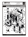
1
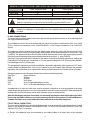
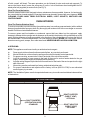
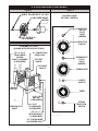
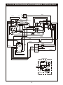
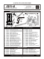
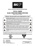
BAKERS
PRIDE
INSTALLATION AND OPERATING INSTRUCTIONS
GAS CONVECTION OVEN
Model: CO11-G
INTENDED FOR OTHER THAN HOUSEHOLD USE
RETAIN THIS MANUAL FOR FUTURE REFERENCE
OVEN MUST BE KEPT CLEAR OF COMBUSTIBLES AT ALL TIMES
IMPORTANT INSTRUCTIONS
After the gas supply has been connected to your unit, it is extremely important to check piping for possible
leaks. To do this, use soap and water solution or solutions which are expressly made for this purpose.
DO NOT USE matches, candles, flames, or other sources of ignition since these methods are extremely
dangerous. Post in a prominent location instructions to be followed in the event you smell gas. Obtain these
instructions from your local gas supplier.
FOR YOUR SAFETY: Do not store or use gasoline or other flammable
!
vapors and liquids in the vicinity of this or any other appliance.
!
!
WARNING: Improper installation, adjustment, alteration, service or
maintenance can cause property damage, injury or death. Read the Installation,
Operating and Maintenance Instructions thoroughly before installing or
servicing this equipment.
!
Initial heating of oven may generate smoke or fumes and must be done in a well-ventilated area.
Overexposure to smoke or fumes may cause nausea or dizziness.
Note: Only Pizza or Bread can have direct contact with ceramic decks. All other food products must be
placed in a pan or container to avoid direct contact with ceramic decks.
This equipment has been engineered to provide you with year round dependable service when used
according to the instructions in this manual and standard commercial kitchen practices.
P/N U4151A 8/07
BAKERS PRIDE OVEN CO., INC.
30 Pine Street
New Rochelle, NY 10801
+1 (914) 576-0200 Phone
+1 (914) 576-0605 Fax
(800) 431-2745 US & Canada
www.bakerspride.com Web Address
[email protected] e-mail Address
1
INDEX
I. INSTALLATION INSTRUCTIONS
SECTION ITEM
A
B
C
D
E
F
G
H
I
PAGE
Receiving
Set-Up Mounting
Installation with Casters (Optional)
Location and Minimum Clearances
Gas Connection
Electrical Connection
Flue Connections-Ventilation
Burner Operation
System Check - Rotary Control
SECTION ITEM
2
2
3
3
4
4
5
5
5
3
4
5
6
7
8
9
10
II. OPERATING INSTRUCTIONS
1
2
General Instructions
System Operation Sequence
6
6
PAGE
A) Cook Only
B) Timed Cooking
C) Cook & Hold
D) Steam Injection
E) Oven Cool Down
Cleaning
Servicing
Illustrations
Electrical Schematic - Rotary Control
Wiring Diagram - Rotary Control
Wiring Diagram - Programmable Control
Replacement Parts & Exploded Views
Warranty
6
6
6
7
7
7
8
8
10
11
12
13
16
NOTE: For units with programmable controls a C&H-3 Plus Controller Manual is shipped under separate cover.
TM
INSTALLATION INSTRUCTIONS
A. RECEIVING:
Read the notice on the outside carton regarding damage in transit. Damage discovered after opening the
carton is "CONCEALED DAMAGE". Carrier must be notified immediately to send an inspector and to
furnish forms for claims against the carrier.
When the oven arrives, it should consist of:
!
!
!
A crate or carton containing your new oven (two for a stacked unit).
A carton containing four 30" legs with mounting hardware ( A set of four 6" legs is supplied for
stacked installations).
A carton containing a Flue Adapter and/or an optional Draft Hood for Direct Venting ( Not available
for European Community Countries)
B. SET UP/ MOUNTING:
In MASSACHUSETTS: All gas products must be installed by a “Massachusetts” licensed plumber or gas
fitter. Ventilation hoods must be installed in accordance with NFPA-96, current edition, with interlocks as
described in that standard.
NOTE: This appliance must be installed by competent person in accordance with the rules in force.
In the U.K. Corgi registered installers (including the regions of British Gas) undertake to work to safe and
satisfactory standards. This appliance must be installed in accordance with the current Gas Safety
(Installation and Use) Regulations and the relevant Building Regulations/lEE Regulations. Detailed
recommendations are contained in the British Standard Codes Of Practice B.S. 6172, B.S. 5440:Part2 and
B.S. 6891.
Your oven will be packed sitting on its bottom. The skid may be left under the oven for convenience in further
handling. Unpack carefully, avoiding damage to the Stainless Steel front and/or trim. If concealed damage
is found, follow the instructions detailed in Section A (Receiving). Keep the area around the ovens free and
clear of combustible materials. Do not store any materials on top of or under any oven. The provision of
adequate air supply to your oven for ventilation and proper gas combustion is essential. As a minimum,
2
observe the clearances detailed in Section D (Location). Provide adequate ventilation and make up air in
accordance with local codes. Servicing your oven is done through the front control panel and right side
access cover. Assure that these areas are kept unobstructed for easy access.
For a single unit:
(1)
Tilt Oven over onto left hand side, and attach two 30" legs on the right hand side with three 1/2" bolts
and washers. Tighten firmly.
(2)
Using proper lifting equipment lift up the Ieft hand side and attach two 30" legs on the left hand side
the same way.
For a stack of two ovens:
(1)
Tilt lower unit over onto the left hand side, attach two mounting plates to the right hand underside
and screw 6" legs into the center holes.
(2)
Using proper lifting equipment lift up the left hand side and attach the mounting plates and 6" legs as
in (Step1 ).
(3)
Using the lifting equipment, raise the top oven to proper height and slide on top of the bottom oven.
Line up sides and front of both ovens and fasten to each other with stacking brackets.
All legs for the CO11-G 1 and CO11-G2 as well as the base cabinet have a leveling adjustment. Start with
adjustment screwed all the way in. With a spirit Ievel placed on an oven rack, check and level side to side
first and then front to back.
Fit the Standard Flue Diverter supplied (Figure 1) into the hole in the top of the oven (for under ventilation
hood installation) and secure with screws. For direct venting. The Flue Adapter and the Draft Hood must be
placed into the hole on top of the oven(Figure 2).
To assemble an open rack stand: Refer to fig.3
(1)
Loosen 12 bolts( attaching 30" legs) slightly.
(2)
Remove 4 inner bolts, 1 from each of the four legs. Place top right angle and top left angle
underneath and tighten these 4 bolts.
(3)
Insert Open Rack Shelf and tighten into place with eight 3/8-16 screws, washers and nuts.
(4)
Position 'Rack Supports' and tighten in place using 4 each of Flat washers and 5/16-18 Hex Nuts.
To assemble over a Base Cabinet:
(1 )
Tilt cabinet over onto the left hand side. Attach two mounting plates to the right underside and screw
6" legs into the center holes.
(2)
Lift up left hand side of the base cabinet and attach the mounting plates and 6" Iegs on the
underside and screw 6" legs into center holes.
(3)
Using the lifting equipment, raise the top oven to proper height and slide on top of the base cabinet.
Line up sides and front and fasten to each other with stacking brackets.
C. INSTALLATION WITH CASTERS (OPTIONAL):
Four casters (two with wheel brakes) and the mounting hardware are packed and included in the shipment
if ordered.
Install casters with wheel brakes on the front of the unit.
Installation of the unit should be made with a connector that complies with the latest edition of the Standard
for Connectors for Movable Gas Appliances ANSI Z21.69, in the USA (CAN CGA-6.16 in Canada) and a
quick disconnect device that complies with the latest edition of the standard for quick disconnect devices
for use with gas fuel ANSI Z21A I in the USA (CAN 1-6.7 in Canada.) Adequate means must be provided to
limit the movement of the appliance without depending on the connector and any quick disconnect device
or its associated piping to limit the appliance movement.
The restraint should be attached to the rear legs of the oven on which casters are mounted. If disconnection
of the restraint is necessary, the restraint should be reconnected after the appliance has been returned to
its originally installed position.
D. LOCATION AND MINIMUM CLEARANCES:
Move the oven to its final location keeping the minimum clearance from the back of the oven to the wall.
This clearance is necessary for safe operation and to provide proper air flow to the burner chamber.
3
MINIMUM CLEARANCES FROM COMBUSTIBLE AND NON-COMBUSTIBLE CONSTRUCTION
RIGHT WALL
LEFT WALL
REAR WALL
Under Ventilation Hood
1”
1"
3"
Direct Venting
1"
3"
3"
q
!
CAUTION: Do not set the oven with its back flat against the wall. It will not operate
properly unless there is at least three inches breathing space behind the oven.
!
!
Suitable for installation on combustible floor when installed with legs or casters
provided.
!
E. GAS CONNECTIONS:
The ovens should not be installed on the same gas line with space heaters, boilers or other gas equipment
with high intermittent demand.
The installation of this oven must conform with the latest local codes or Nationa/Fuel Gas Code. ANSI
Z223.1, Natural Gas Installation Code. CAN/CGA-BJ49.1. or the Propane Installation Code. CAN/CGABJ49.2
The appliance must be isolated from the gas supply piping system by closing it’s manual shut-otf valve
during any pressure testing of the gas supply piping system at test pressures equal to or less than ½ psi
(3.45kPa). The appliance and its shut-off valve must be disconnected from the gas supply piping system
during any pressure testing of that system at test pressures in excess of ½ psig (3.45kPa).
Use a pipe joint compound that is resistant to the action of liquefied petroleum gases when making gas
Connections. For Propane gas, use at least 1/2" (13 mm) pipe or tubing with a 5/8" (16 mm) inside diameter.
For Natural gas, use 3/4" (19 mm) pipe.
The gas pressure regulator is part of the combination valve and is adjusted to yield a pressure of 3.5" water
column (9mbar) for Natural Gas. If the oven is ordered for use on Propane Gas or Butane the pressure
regulator in the combination valve is preset at the factory to yield a pressure of 10" water column (25 mbar).
Gas supply pressure in the European Community countries should be as below:
Gas Type
Supply Pressure
G20
20 mbar
G25
25 mbar
G20/25
20/25 mbar
G30
30 or 50 mbar depending on country
G31
30, 37, or 50 mbar depending on country
A separate shut-off valve for each oven must be provided. It should be as close as possible to the place
where the gas line goes into the oven. It must be located such that it is easily accessible. When stacking with
another oven, two shut-off valves, one for each of the two ovens, must be provided.
After the Gas Supply has been connected, it is extremely important to check all the piping for leaks.
Use a soap and water solution or a product expressly made for this purpose. Do not use Matches,
Candles or a Flame etc to check leaks since these methods are extremely dangerous.
F. ELECTRICAL CONNECTION:
The oven when installed must be electrically grounded in accordance with local codes/and/or the latest
edition of the National Electrical Code ANSI/NFPA No. 70 in the USA (Canadian Electrical Code CSA
Standard C22.I, Part 1 in Canada).
In Europe, the appliance must be connected by an earthing cable to all other units in the complete
4
installation and thence to an independent earth connection in compliance with EN 60335-1 and/or local
codes.
The electric motor, all the related switches, interior lights and the timer/buzzer, are all connected through
the 6ft (1829 mm) power supply cord located at the rear of the oven. The supply cord must be plugged into a
properly grounded three-prong receptacle. DO NOT CUT OR REMOVE THE GROUNDING PRONG
FROM THE PLUG.
Normal factory connections are made for 115 volts AC., 60 Hz. Service in USA and Canada or 230Volts AC,
50 Hz service in European Community Countries. Other voltages can be supplied upon request. Electrical
characteristics of this unit can be found on the rating plate located on the right side of the unit.
This unit is provided with a permanently lubricated electric motor. A wiring diagram may be found on the
back of the service panel on the right hand side and in this manual.
G. FLUE CONNECTION - VENTILATION:
(a) INSTALLATION UNDER VENTILATION HOOD (STANDARD):
If the oven is not vented directly and is installed under a ventilation hood, use the flue diverter (Fig. 1)
supplied. Local inspectors and ventilation specialist should be consulted so that the design and the
installation of the hood conforms to local/municipal codes.
In U.K. ventilation requirements as detailed in B.S. 5440 should be followed.
(b) OPTIONAL DIRECT VENTING-NOT AVAILABLE FOR EUROPEAN COMMUNITY COUNTRIES:
If direct venting, a flue adapter and a draft hood (fig.2) are required to be installed. These prevent the flue
gases leaving the oven from being affected by the air pressure changes on the outside of the flue stack
extending out of the building. The flue pipe from the draft hood must not run downwards at any point from
the oven to the final outlet. It should always slant slightly upwards. For best results it should rise straight up
NOTE: DO NOT PUT A DAMPER IN THE FLUE AND DO NOT CONNECT A BLOWER DIRECTLY TO
THE FLUE.
If the flue runs directly to the free air outside the building, use a wind deflector or a UL listed vent cap at the
end of the pipe. Termination of the vent must be at least two feet above the highest part of the roof within ten
feet. REF: AGA CATALOG NO. XH0474.
H. BURNER OPERATION:
The oven burner flame should always have a blue appearance. This indicates a good mixture of air and gas.
When using LP gas the flame will have a blue yellow appearance. There may be intermittent yellow-orange
flame noticed. This is caused by dust particles burning in the flame.
I. SYSTEM CHECK - ROTARY CONTROL:
I)
2)
3)
4)
5)
6)
7)
8)
9)
10)
Open the oven door.
Turn Selector Switch to 'Hi'. The indicator light near Selector Switch and oven light will illuminate.
Close the door. Oven lights will go off and fan will run. Make sure fan is rotating clockwise looking
from front.
Press Oven Light switch. Oven light will go on and will go off as switch is released.
Turn Gas Cock Dial to 'ON' position.(only for USA & Canada)
Turn the thermostat knob. The indicator light near the thermostat will Illuminate and the burners will
come on.
Turn the Timer Knob and set a time of 2 minutes. At the end of 2 minutes, you should hear the
buzzer. Turn the timer knob to '0' to reset.
Open the oven doors. Oven lights will go on, and burners and fan will go off.
Turn Selector switch to 'Cool Down' position. The fan will run to cool down the oven.
Turn Selector Switch to '0' position.
5
11)
12)
Close the oven doors.
Turn Gas Cock Dial to 'Off position.(only for USA & Canada)
NOTE: OVEN WILL START HEATING AS SOON AS THE SET TEMPERATURE IS HIGHER THAN THE
OVEN TEMPERATURE, THE OVEN DOORS CLOSED AND THE SELECTOR SWITCH IS IN ANY
POSITION EXCEPT ‘0’.
THERMOSTAT INDICATOR LIGHT GOES OUT WHEN OVEN REACHES SET TEMPERATURE AND
COMES ON WHEN OVEN IS HEATING UP.
IN THE EVENT OF POWER FAILURE, THE OVEN WILL NOT OPERA TE.
II. OPERATING INSTRUCTIONS
1. GENERAL INSTRUCTIONS:
(a)
This equipment has an Electronic Temperature Control and Electronic Hot Surface Direct Ignition
System.
(b)
Due to the increased efficiency of this oven, the temperature of standard recipes may be reduced
50°F (30°C).
(c)
Always load each shelf evenly. Space pans away from each other and from sides and back of oven
to allow maximum air flow between them.
(d)
Large tempered glass windows and interior lights allow visual checks on the product making it
unnecessary to frequently open the doors. Products cook faster in a convection oven as compared
to a conventional oven. Depending on the product and the type of pans used, time savings may run
from 20% to as high as 50%.
2. OPERATION SEQUENCE-ROTARY CONTROL:
A. COOK ONLY-ROTARY CONTROL:
(1)
Close the oven doors.
(2)
Turn Selector Switch to 'HI' or 'LO' position. The indicator light near the Selector Switch will be
illuminated.
(3)
Turn the thermostat knob to the desired cooking temperature.
(4)
Upon reaching the set temperature, the indicator light near the thermostat will go out.
/5)
Load the oven with product to be cooked.
(6)
Remove the product from the oven when done.
B. TIMED COOKING-ROTARY CONTROL:
(I)
Close the oven doors.
(2)
Turn Selector Switch to 'HI" or 'LO' position . The indicator light near the Selector Switch will be
illuminated.
(3)
Turn the thermostat knob to the desired cooking temperature.
(4)
Upon reaching the set temperature, the indicator light near the thethermstat will go out.
(5)
Load the oven with product to be cooked.
(6)
Turn the timer knob to the desired bake time and timer will start counting down.
(7)
When timer reaches zero, a buzzer will sound.
(8)
Turn the timer knob to '0' position.
(9)
Remove the product from the oven.
NOTE: TIMER DOES NOT CONTROL THE OVEN.
C. COOK & HOLD-ROTARY CONTROL:
(I)
Close the oven doors.
(2)
Turn Selector Switch to 'HI' or 'LO' position. The indicator light near the Selector Switch will be
illuminated.
(3)
Turn the thermostat knob to the desired cooking temperature.
(4)
Upon reaching the set temperature, the indicator light near the thermostat will go out.
6
(5)
(6)
(7)
(8)
(9)
(10)
Load the oven with product to be cooked.
Turn the timer knob to the desired bake time and timer will start counting down.
When timer reaches zero, a buzzer will sound.
Turn the Timer knob to '0' position to reset.
Turn the thermostat knob to the desired hold temperature.
Remove the product from the oven when done.
D. OPTIONAL STEAM INJECTION-ROTARY CONTROL:
The solenoid valve for steam injection is mounted behind the service panel on the right hand side of the unit.
The electronic timer is preset at the factory. A 1/4" copper tubing is provided on the Solenoid Valve for water
hookup with a compression fitting. After the water hookup is made, make sure that there are no leaks. For
steam injection, press the Steam switch momentarily.
NOTE: Do not use steam injection at temperatures below 275°F (135°C).
E. OVEN COOL DOWN-ROTARY CONTROL:
To cool down the oven to a lower desired temperature, follow the steps detailed below:
(1)
Open the oven doors.
(2)
Turn Selector Switch to 'oven cool down' position. Fan will now operate and cool down the oven.
(3)
When the oven has cooled down to the desired temperature, turn the selector switch to the ‘O’
position. Close oven doors.
CLEANING
Always clean equipment thoroughly before first use. Clean unit daily.
!
WARNING: To avoid any injury, turn the power switch off at the fuse disconnect switch/circuit
breaker or unplug the unit from the power source and allow to cool completely before performing
any maintenance or cleaning.
!
!
WARNING: Unit is not waterproof. To avoid electrical shock or personal injury, DO NOT submerge
in water. DO NOT operate if it has been submerged in water. DO NOT clean the unit with a water jet.
DO NOT steam clean or use excessive water on the unit.
!
!
CAUTION: Use mild detergent or soap solution for best results. Abrasive cleaners could scratch
the finish of your unit, marring it’s appearance and making it susceptible to dirt accumulation. DO
NOT use abrasive cleaners or cleaners/sanitizers containing chlorine, iodine, ammonia or bromine
chemicals as these will deteriorate the stainless steel and glass material and shorten the life of the
unit. Use nylon scouring pads. DO NOT use steel wool.
!
OVEN INTERIOR:
Clean The Racks And Rack Support Guides:
Open the doors and remove all wire racks and rack support guides. Take them to the sink and thoroughly
clean in warm water with mild detergent or soap. Use a nylon scouring pad or stiff nylon brush.
DO NOT USE STEEL WOOL.
Clean The Stainless Steel Interior:
Baked on splatter, oil, grease or discoloration on the stainless steel inside of the oven may be removed with
stainless steel cleaner, or any other similar cleaning agent. NEVER use vinegar or any corrosive cleaner.
Use only cleaners approved for stainless steel. NEVER use cleaning solvents with a hydrocarbon base.
NEVER use a wire brush, steel or abrasive scouring pads, scraper, file or other steel tools.
NOTE: ALWAYS RUB THE STAINLESS STEEL ALONG THE GRAINS.
Clean The Blower Wheel:
To clean the blower wheel, remove and immerse in ammoniated water for 20 to 25 minutes. Then, scrub it
7
off with a small, stiff brush. The same procedure can be followed for wire racks and rack supports. To
remove the blower wheel, loosen the set screws (2) on the hub of the blower wheel and tighten the 3/8”
wheel puller bolt (supplied) in center of hub (See Fig. 3).
Clean The Porcelain Interior:
Porcelain enamel interiors are designed to be as maintenance free as possible. However, for best results,
the oven should be cleaned regularly. Enameled interiors can be easily cleaned with oven cleaners. KEEP
CLEANING FLUIDS AWAY FROM ELECTRICAL WIRES, LIGHT SOCKETS, SWITCHES AND
CONTROL PANEL.
OVEN EXTERIOR:
Clean The Exterior Stainless Steel:
To remove normal dirt or product residue from stainless steel, use ordinary soap and water (with or without
detergent) applied with a sponge or cloth. Dry thoroughly with a clean cloth. Never use vinegar or corrosive
cleaner. Do not use chorine based cleaners.
To remove grease and food splatter or condensed vapors that have baked on the equipment, apply
cleaners to a damp cloth or sponge and rub cleanser on the metal in the direction of the polished lines on the
metal. Rubbing cleanser as gently as possible in the direction of the polished lines will not mar the finish of
the stainless steel. To remove discoloration, use a non-abrasive cleaner. NEVER use a wire brush, steel or
abrasive scouring pads, scraper, file or other steel tools. NEVER RUB WITH A CIRCULAR MOTION.
4. SERVICING:
NOTE: This appliance must be serviced by an authorized service agent.
a)
b)
c)
d)
e)
f)
g)
Power supply to the unit must be disconnected before any service is performed.
Most of the service on the unit can be performed from the front and/or control panel side.
For proper servicing, access to the Control Panel side of the unit will be required.
It will be necessary to have access to the back of the oven for service needs related to the gas
supply , electric power supply and steam injection plumbing.
A system wiring diagram is provided in this manual and on the back of the service panel on the right
side of the oven.
All servicing must be performed by a factory authorized technician only.
For proper maintenance and repairs call the factory toll free (800-431-2745) for an authorized
service agency in your area.
NOTE: The Ventilation System must he inspected at least every six months and maintained clean and free
of obstructions.
5. ILLUSTRATIONS
Figure 1
Figure 2
DRAFT DIVERTER
(DIRECT VENT)
OPTIONAL
DRAFT DIVERTER
(VENTILATION HOOD)
STANDARD
DRAFT ADAPTOR
(DIRECT VENT)
OPTIONAL
8
5. ILLUSTRATIONS (CONTINUED)
Figure 3
Figure 5
WHEEL PULLER BOLT 3/8”-HEX
BLOWER WHEEL
MOTOR
CONTROL PANEL
(ROTARY CONTROL)
SELECTOR
SWITCH
PILOT
LIGHT
(GREEN)
SET SCREW (2)
SELECTOR
SWITCH
Figure 4
ASSEMBLY OF LEGS
(SHOWN WITH OPEN RACK STAND)
3/8”-16 x 3/4”
TRUSS HEAD
SCREW
w/NUT & WASHER
(8 REQUIRED)
30” CONVECTION
OVEN LEGS
THERMOSTAT
PILOT
LIGHT
(AMBER)
TOP LEFT
ANGLE
TOP RIGHT
ANGLE
THERMOSTAT
LIGHTS
SWITCH
RACK
SUPPORT
TIMER
5/16”-18
HEX NUT
(4 REQUIRED)
OPEN RACK
SHELF
STEAM
INJECTION
SWITCH
5/16”
FLATWASHER
(4 REQUIRED)
1/2”-13 x 1”
HEX HEAD BOLT
(12 REQUIRED)
1/2” FLATWASHER
(4 CORNERS ONLY)
9
6. CO11-G ELECTRICAL SCHEMATIC (ROTARY CONTROL)
Power
120VAC
X 0...60'
O0 -
1
Coil
Timer
2
S
TIMER M450
X0O 0...60'
4
Steam Potentiometer
Factory Set (8 Seconds)
6
7
Coil
4
BUZZER
3
SSAC
Steam
Button
5
Solenoid
Valve
1
2
NOTO
120V
24V
ground
l1
Ignition
Module
Valve
valve
Gas Control
RAM
ignitor
therm.
sensor
NO
COM
Door
Switch
Fan Rotary
Switch
(Off, Low, High,
Cool Down)
Ignitor
Flame Sensor
Amber Pilot Light
(Thermostat)
L1
L2
GC-20
Temperature Controller
Green Pilot Light
(Power)
NO
oxxo
1
P1
CO
LO
oxoo
NC
COM
2
P2
ooxo
HI
3
P3
2 Speed Motor
ooox
P4
4
Interior Lights
Interior Lights
(Momentary Switch)
10
7. CO11-G WIRING DIAGRAM (ROTARY CONTROL)
120VAC
steam switch
potentiometer
timer S
M450
6
5
4
7
3
2
1
steam timer
1
blk
yel
red
blu
2
3
4
solenoid
valve
120v
24v
ignitor
L1-24vac
thermostat
valve hot
ground
flame sensor
PILOT
combination control
VR 8205
IN
COM
FF
RAM
ignitor
NO
L2
flame rod
L1
Pilot Light
(Thermostat)
Rotary
Switch
P1
1
P2
2
P3
3
P4
4
LO
Pilot Light
(Power)
COM
HI
light switch
C
NO
NC
Door
Switch
11
8. CO11-G WIRING DIAGRAM (w/PROGRAMMABLE CONTROLS) C&H-3
WT [2]
N
A
120 V
BLK [11]
BRWN [ ]
L1
BRWN [ ]
BLK [13]
Rotary
Switch
BLK [1]
1
P1
120 V
2 Speed Motor
P2
2
P3
3
P4
4
WT [S1]
WT [ ]
LO
R1
COM
WT [ ]
WT [S2]
HI
BLK [S]
BLK [5]
NO Closed
NO
CO
Door
Sw.
BLK [21]
R2
BLK [3]
BLK
BLK [C1]
Lights Switch
WT
WT [ ]
NC Open
NC
B
WT [ ]
BLK [19]
BLUE [10]
WT
WT [C2]
120 V Lights
WT [8]
120V
BLK [9]
BLK [23]
120 V
BLK [17]
RAM
BLK [15]
T5 T4 T3 T2
T8
CH-100
T9
FAST
T7
GREY
[7,8]
T6
T12
T13
WT [4]
GDN
Orange
Black
T11
T10
Valve
Thermostat
Sensor
L1
Igniter
24V
Grn/Ylo
VR8605A
T2
BLU
BLU
VALVE
Purple
Sensor
RED
Ignitor
BLUE [10]
BLUE [12]
D2
BLU
GREY
[26,27]
RTD Probe
STEAM OPTION
H2
B
R
N
A
H1 BRN
STEAM SWITCH
POTENTIOMETER
A1
STEAM TIMER
1
4 31 BLU
2
5
6 H1
3
7
B
29 BLU
H2
BLK
A2 BRN
YEL
RED
A1 BLU
BLU
BUTT
CONNECTOR
12
WATER SOLENOID
VALVE
9. PARTS LISTS & EXPLODED VIEWS
30 Pine Street • New Rochelle • New York • 10801
CO11-G
914 / 576 - 0200
914 / 576 - 0605 fax
1 - 800 - 431 - 2745 US & Canada
www.bakerspride.com web address
Full Size Gas Convection Oven
Burners / Valve / Door Chain / Legs
Figure B
29
33
32
31
26
30
Door Chain Assy
39
35
36
12
22
27
28
IN
21
11
38
IN
18
OUT
Safety Valve
40
24
16
41
20
2
19
Item
1
2
3
4
5
6
7
8
9
10
11
12
13
14
15
16
17
18
19
20
21
22
Burners
Part #
S1050Y
Q4017V
S1217Y
S1252T
S1081X
S1022X
S1023X
K1357E
S1049Y
S1049A
E3148X
E3149X
T3051X
T3052X
T8075X
R3180A
R3175A
R3176A
R3161X
R3160X
M1233X
M1343A
37
24
25
17
34
BAKERS
PRIDE
23
10
9
8
7
6
5
4
3
1
42
13
15
14
43
Legs & Open Rack Stand
Description
30" Leg (Set of 4)
Leg Bolt, Set (For 4 Legs)
24 1/2" S/S Leg (Set/4) Used w/Casters
24 1/2" S/S Leg (each) Used w/Casters
Casters, 4" (Set of 4)
Caster, 4" (No Lock), each
Caster, 4" (w/Lock), each
Mounting Plate (for Casters) each
6" Bullet Legs (Set of 4)
6" Bullet Legs (each)
Top Right Angle, Open Rack Stand
Top Left Angle, Open Rack Stand
Left Rack Support, Open Rack Stand
Right Rack Support, Open Rack Stand
Bottom Shelf w/Hdwr, Open Rack Stand
#48 Burner Orifice Spud (Nat)
#57 Burner Orifice Spud (LP)
1.15mm Burner Orifice Spud CE (LP)
#71 Carry-Over Orifice Hood (Nat)
#78 Carry-Over Orifice Hood (LP)
LP Kit (for Combination Valve)
Natural Kit (for Combination Valve)
Item
Part #
23
24
25
26
27
28
29
30
31
32
33
34
35
36
37
38
39
40
41
42
43
N3068P
N3026A
R3158A
L5090A
L5091X
M1323X
M2140X
R3164X
R3165X
R3178P
R3179P
R1116A
S3228A
S3231X
S3226A
S3227A
S3145X
S3112X
S3224A
S3223A
Q2039A
Description
1/8" Pressure Tap Nozzle Assy
1/2" Union
Carry-Over
Burner (3)
Burner w/Ignitor Bracket (1)
Flame Rod (Flame Sensor)
Igniter, 24V
Combination Valve (Natural)
Combination Valve (LP)
Combination Valve, CE (Natural)
Combination Valve, CE (LP)
Manifold
Flange Bearing (4)
Door Chain Assy (Complete)
Door Chain Rod (Short)
Door Chain Rod (Long)
Sprocket
Roller Chain #35
Chain Connection Link #41
Turnbuckle 1/4-20x3"
1/4-20 Hex Nut, L.H. Thread (2)
Steam Option (Not Shown)
N/S
N/S
N/S
N/S
N/S
N/S
N/S
M1114X
M1115X
N3039A
N3040A
N5831A
N3041A
N5814A
Page 4 of 4
Solonoid Valve
Coil (For Solenoid Valve)
1/8 Brass Coupling
1/8 Brass Elbow
1/8x4" Brass Nipple
1/8NPT-1/4 Compression Fitting
1/8x2 3/8 Nipple
N/S
N/S
N/S
N/S
N/S
N/S
N5815A
N1019X
M1175X
M1231A
M1176X
M1049X
1/4 Tubing x 9"
Steam Injection Nozzle
Steam Timer, 115V
Steam Timer, 208/240V (Export)
Steam Potentiometer
Momentary Switch (Steam)
Note: When ordering, ALWAYS specify Part #, Model #, Serial #,Voltage/Phase & type of Gas.
13
U6003A 8/07
30 Pine Street • New Rochelle • New York • 10801
CO11-G
914 / 576 - 0200
914 / 576 - 0605 fax
1 - 800 - 431 - 2745 US & Canada
www.bakerspride.com web address
Full Size Gas Convection Oven
BAKERS
PRIDE
Exterior / Interior / Controls / Doors
Figure A
81 82 83 84 85
36
45
10
8
35
16
1
12
55
56
44
2
88
90
34
89
37
6
5
91
BA
KE
RS
PR
ID
E
4
9
42
49
20
50
19
21
48
22
47
7
11
18 17
46
54
52
53
51
3
93
23
72
41
71
87
25
24
70
43
13
86
73
57
78
74
80
75
69
79
68
60
29
28
26
27
30
D
oor Switc
94
62
95
92
61
58
h
58
76
75
65
39
66
40
63
32
58
64
31
75
59
14
Page 2 of 4
Note: When ordering, ALWAYS specify Part #, Model #, Serial #,Voltage/Phase & type of Gas.
14
67
38
15
U6003A 8/07
30 Pine Street • New Rochelle • New York • 10801
BAKERS
PRIDE
Item
CO11-G
914 / 576 - 0200
914 / 576 - 0605 fax
1 - 800 - 431 - 2745 US & Canada
www.bakerspride.com web address
Part #
Full Size Gas Convection Oven
Description
Item
Part #
Description
Exterior / Interior / Controls / Doors
1
2
3
4
5
6
7
8
9
10
11
12
13
14
15
16
17
18
19
20
21
22
23
24
25
26
27
28
29
30
31
32
33
34
35
36
37
38
39
40
41
42
43
44
45
46
47
48
E3450X
E3451K
E3466U
S1317U
Q1477A
Q3047A
E3487X
E3485K
E3486K
E3501K
E3499X
E3488X
E3583U
E3498X
S3203K
E3514X
E3454X
E3458X
E3456X
E3460X
S3229A
Q4033A
S1048X
E3053K
Q2009A
E3095X
Q1414A
E3481X
E3482X
E3511X
E3471K
M1102X
Door Seal, Top or Bottom, each (2)
Door Seal, Sides, each (2)
Door Closure Strip
Door Handle
Screw, FH 10-32x1/2 (4)
#10 Lockwasher, Countersunk, Ext. (4)
Vertical Trim
Outer Cover (Left)
Outer Cover (Right)
Outer Cover (Top)
Access Cover (Side)
Top Trim
Bottom Apron
Access Cover (Front)
Latch Assy (Magnetic)
S/S Perforated Rear Panel
Door Assy Left (No Window)
Door Assy Left (w/Window)
Door Assy Right (No Window)
Door Assy Right (w/Window)
Door Rod
Roll Pin 1/4 x 1 1/4
Window Assy
Baffle Plate
Thumb Screw, 1/4-20x1/2 (4)
Baffle Plate Bracket Assy (4)
Screw, Hex Hd, #10x3/4 (8)
Combustion Chamber (Front Center)
Combustion Chamber (Front Left)
Combustion Chamber (Front Right)
Door Switch Actuator
Microswitch (Rotary)
R3166A
R3113A
R3167A
U1043X
U1290A
U1437A
U1296A
U1216A
U1055A
U1128A
U1169A
U1210A
P6004X
P6005X
P6006X
Flue Adapter 7" (For Direct Venting Only)
Flue Diverter (For Direct Venting)
Flue Diverter (For Collection Hood)
Bakers Pride Name Plate (13 3/4")
Control Panel Overlay (Rotary)
Control Panel Overlay (FAST)
Timer Overlay (50 cycle only)
Rating Plate
Caution Hot Label
Supply Connection
Motor Rotation Arrow
Installation Warning
Elec Line Cord, 115V (US & Can)
Elec Line Cord, 250V (US & Can)
Elec Line Cord, 250V (Europe)
49
50
51
52
53
54
55
56
57
58
59
60
61
62
63
64
65
66
67
68
69
70
71
72
73
74
75
76
77
78
79
80
81
82
83
84
85
86
87
88
89
90
91
92
93
94
95
Conversion Kit (Natural to LP)
4
1
1
Elec Line Cord, 250V (UK)
Rear Pipe Connection
Snap-In Light Assy (w/130V Bulb)
Snap-In Light Assy (w/240V Bulb)
Light Bulb (15W, 130V)
Light Bulb (15W,240V)
Conduit BX, 3/8"
Bushing, Anti-Short, 3/8"
Terminal Block (3 Pole)
Switch, Momentary (Light &/or Steam)
Plug Button, 7/16"
Switch, Rotary (EGO)
Pilot Light Amber (Thermostat)
Pilot Light Green (Power)
Timer, 60 Minutes (120V)
Timer, 60 Minutes (208/240V)
Ignition Control Module (24V)
Ignition Control Module, CE (24V)
Harness w/Terminals
T-stat, G6, FAST (Domestic)
T-stat, E6, FAST (CE)
Probe, RTD Temp
Clamp, Temperature Sensor (1)
Victor Clip, Temp Sensor (3)
Potentiometer
Bell Audiolarm
Knob (3)
Ckt Breaker, 120-240V, 15A
M1356A
M1145X
M1174X
M1157X
M1217X
Q3008A
Q3014A
Q2204A
S1195X
Q2302A
P1108A
E3225X
T3044A
T3043A
E3483K
E3531K
M1175X
M1231A
Solid State Relay, CE
Transformer (120V-24V)
Transformer (208/240V-24V)
Motor, 1/4HP, 2Spd, 115V, 60
Motor, 1/4HP, 2Spd, 200-230V,50-60
Flat Washer (4)
Lock Washer, Split (4)
Nut, 5/16 HX, 5/16-18 (4)
Blower Wheel
Bolt, Wheel Puller 3/8-16x2 Hx (2)
Conduit Connector, 3/8"x1/2", 90 deg.
Stacking Bracket, CO11-G2 Only (Each)
Rack Support
Wire Rack
Flame Guard
Door Limit Block
Steam Timer, 115V
Steam Timer, 208/240V (Export)
Conversion Kit (LP to Natural)
R3175A #57 Burner Orifice Spud, LP
M1233X LP Kit for Combination Valve
R3160X #78 Carry-over Orifice Hood, LP
Page 3 of 4
P6007X
N5048P
P1144X
P1145X
P1146X
P1147X
P1082A
P1084A
P1003X
M1049X
S1171A
M1326X
M1339A
M1340A
M1332X
M1346X
M2138X
M1355A
M2139A
M0110A
M1553A
M1555A
E3051K
P1042A
M1176X
M1335X
S1311X
M1352X
4
1
1
R3180A #48 Burner Orifice Spud, Nat
M1343X Natural Kit for Combination Valve
R3161X #71 Carry-over Orifice Hood, Nat
Note: When ordering, ALWAYS specify Part #, Model #, Serial #,Voltage/Phase & type of Gas.
15
U6003A 8/07
10. BAKERS PRIDE LIMITED WARRANTY
30 Pine Street New Rochelle, New York 10801
914 / 576 - 0200 ♦ US & Canada: 1 - 800 - 431 - 2745 ♦ fax 914 / 576 - 0605
WHAT IS COVERED
This warranty covers defects in material and workmanship under normal use, and applies only to the original purchaser
providing that:
♦ The equipment has not been accidentally or intentionally damaged, altered or misused;
♦ The equipment is properly installed, adjusted, operated and maintained in accordance with National and local codes. and
in accordance with the installation instruction provided with the product;
♦ The serial number rating plate affixed to the equipment has not been defaced or removed.
WHO IS COVERED
This warranty is extended to the original purchaser and applies only to equipment purchased for use in the U.S.A.
COVERAGE PERIOD
Full size gas and electric deck ovens: Two (2) year limited parts and labor: Cyclone Convection Ovens: BCO Models: One (1)
Year limited parts and labor; GDCO Models: Two (2) Year limited parts and labor; CO II Models: Two (2) Year limited parts
and labor; (5) Year limited door warranty.
All Other Products: One (1) Year limited parts and labor.
Warranty period begins the date of dealer invoice to customer or ninety (90) days after shipment date from BAKERS PRIDE whichever comes first.
WARRANTY
COVERAGE
This warranty covers on-site labor, parts and reasonable travel time and travel expenses of the authorized service
representative up to (100) miles. round trip, and (2) hours travel time. The purchaser. however, shall be responsible for all
expenses related to travel, including time. mileage and shipping expenses on smaller counter models that may be carried into
a Factory Authorized Service Center, including the following models: PX-14. PX-16, PI8, and BK-I8.
EXCEPTIONS
All removable parts in BAKERS PRIDE Char-broilers, including but not limited to: Burners, Grates. Radiants, Stones and
Valves, are covered for a period of SIX MONTHS.
All Ceramic Baking Decks are covered for a period of THREE MONTHS. The installation of these replacement decks is the
responsibility of the purchaser.
The extended Cyclone door warranty years 3 through 5 is a parts only warranty and does not include labor, travel, milage or
any other charges.
EXCLUSIONS
♦ Failures caused by erratic voltages or gas supplies,
♦ Unauthorized repair by anyone other than a BAKERS PRIDE
Factory Authorized Service Center,
♦ Damage in shipment,
♦ Alteration, misuse or improper installation,
♦ Thermostats and safety valves with broken capillary tubes.
♦ Accessories - spatulas, forks. steak turners, grate lifters,
oven brushes, scrapers, peels. etc.,
♦ Freight - other than normal UPS charges,
♦ Ordinary wear and tear.
♦ Negligence or acts of God,
♦ Thermostat calibrations after (30) days from equipment
installation date,
♦ Air and Gas adjustments,
♦ Light bulbs,
♦ Glass doors and door adjustments.
♦ Fuses,
♦ Char-broiler work decks and cutting boards,
♦ Tightening of conveyor chains,
♦ Adjustments to burner flames and cleaning of pilot burners,
♦ Tightening of screws or fasteners.
INSTALLATION
Leveling and installation of decks. as well as proper installation and check out of all new equipment - per appropriate
installation and use materials - is the responsibility of the dealer or installer, not the manufacturer.
REPLACEMENT
PARTS
BAKERS PRIDE genuine Factory OEM parts receive a (90) day materials warranty effective from the date of installation by a
BAKERS PRIDE Factory Authorized Service Center.
This Warranty is in lieu of all other warranties, expressed or implied, and all other obligations or liabilities on the manufacturers part. BAKERS PRIDE
shall in no event be liable for any special, indirect or consequential damages, or in any event for damages in excess of the purchase price of the unit. The
repair or replacement of proven defective parts shall constitute a fulfillment of all obligations under the terms of this warranty.
Form #U4177A 1/07
16