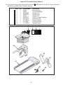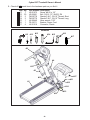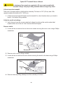
1
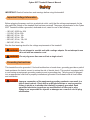
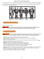
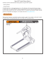
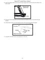
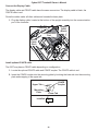
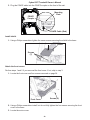
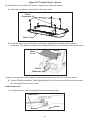
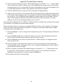
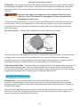
Cybex Treadmill Product Number 625T Owner’s Manual Cardiovascular Systems Part Number LT-23221-4 B www.cybexintl.com Cybex Treadmill Product Number 625T Owner’s Manual Cardiovascular Systems Part Number LT-23221-4 B Cybex® and the Cybex logo are registered trademarks of Cybex International, Inc. Safety Sentry™ is a registered trademark of Cybex International, Inc. Polar® is a registered trademark of Polar Electro Inc. DISCLAIMER: Cybex International, Inc. makes no representations or warranties regarding the contents of this manual. We reserve the right to revise this document at any time or to make changes to the product described within it without notice or obligation to notify any person of such revisions or changes. © 2011, Cybex International, Inc. All rights reserved. Printed in United States of America. 10 Trotter Drive Medway, MA 02053 • 888-462-9239 • 508-533-4300 • FAX 508-533-5183 www.cybexintl.com • [email protected] • LT-23221-4 B Cybex 625T Treadmill Owner’s Manual Table of Contents FCC Compliance Information . . . . . . . . . . 7 Preventive Maintenance Warnings . . . . . . . . . . . . . . . . . . . . . . . . . Regular Maintenance Activities . . . . . . . . Cleaning Your Treadmill . . . . . . . . . . . . . . Running Belt Maintenance . . . . . . . . . . . . Other Preventive Maintenance . . . . . . . . Service Schedule . . . . . . . . . . . . . . . . . . . Safety Important Voltage Information . . . . . . . . . . 9 Grounding Instructions . . . . . . . . . . . . . . . . 9 Important Safety Instructions . . . . . . . . . . 10 User Safety Precautions . . . . . . . . . . . . . 10 Facility Safety Precautions . . . . . . . . . . . 11 Warning Decals . . . . . . . . . . . . . . . . . . . . 12 Caution Decals . . . . . . . . . . . . . . . . . . . . 15 Emergency Stop Key (e-stop) . . . . . . . . . 16 CSAFE Port . . . . . . . . . . . . . . . . . . . . . . . 17 Customer Service Contacting Service . . . . . . . . . . . . . . . . . . Serial Numbers and Voltage . . . . . . . . . . Return Material Authorization (RMA) . . . . Damaged Parts . . . . . . . . . . . . . . . . . . . . Ordering Parts . . . . . . . . . . . . . . . . . . . . . Assembly and Setup Warnings/Cautions . . . . . . . . . . . . . . . . . . Choosing and Preparing a Site . . . . . . . . Electrical Power Requirements . . . . . . . . Assembling the Treadmill . . . . . . . . . . . . . Setup . . . . . . . . . . . . . . . . . . . . . . . . . . . . Testing the Treadmill Operation . . . . . . . . 19 19 20 20 32 34 57 57 58 58 59 Appendix A - Technical Specifications Specifications . . . . . . . . . . . . . . . . . . . . . . 61 Operation Terms Used . . . . . . . . . . . . . . . . . . . . . . . User Control Symbols Used . . . . . . . . . . Console Display . . . . . . . . . . . . . . . . . . . . User Controls . . . . . . . . . . . . . . . . . . . . . . Quick Operation Guide . . . . . . . . . . . . . . Detailed Operation Guide . . . . . . . . . . . . Stopping the Treadmill . . . . . . . . . . . . . . . Safety Sentry . . . . . . . . . . . . . . . . . . . . . . Control During Operation . . . . . . . . . . . . . Data Readouts . . . . . . . . . . . . . . . . . . . . . Displaying Heart Rate . . . . . . . . . . . . . . . Heart Rate Zone . . . . . . . . . . . . . . . . . . . Meaning of % Grade . . . . . . . . . . . . . . . . Preprogrammed Workouts . . . . . . . . . . . . 49 49 49 50 53 54 37 38 39 39 40 40 43 43 44 44 45 46 46 47 5 Cybex 625T Treadmill Owner’s Manual 6 Cybex 625T Treadmill Owner’s Manual FCC Compliance Information WARNING: Changes or modifications to this unit not expressly approved by the party responsible for compliance could void the user’s authority to operate the equipment. This equipment has been tested and found to comply with the limits for a Class A digital device, pursuant to part 15 of the FCC Rules. These limits are designed to provide reasonable protection against harmful interference when the equipment is operated in a commercial environment. This equipment generates, uses, and can radiate radio frequency energy and, if not installed and used in accordance with the instruction manual, may cause harmful interference to radio communications. Operation of this equipment in a residential area is likely to cause harmful interference in which case the user will be required to correct the interference at his own expense. Modifications not expressly approved by the manufacturer could void the user’s authority to operate the equipment under FCC rules. 7 Cybex 625T Treadmill Owner’s Manual 8 Cybex 625T Treadmill Owner’s Manual Safety IMPORTANT: Read all instructions and warnings before using the treadmill. Important Voltage Information Before plugging the power cord into an electrical outlet, verify that the voltage requirements for the site match the voltage of the treadmill that has been received. The power requirements for the Cybex 625T Treadmill include a grounded, dedicated circuit, rated for one of the following: • 100 VAC, 50/60 Hz, 20A • 115 VAC, 60 Hz, 20A • 208 VAC, 60 Hz, 15A • 220 VAC, 60 Hz, 15A • 230 VAC, 50 Hz, 13A, UK • 240 VAC, 50 Hz, 15A See the front warning decal for the voltage requirements of the treadmill. WARNING: Do not attempt to use this unit with a voltage adapter. Do not attempt to use this unit with an extension cord. WARNING: Do not plug more than one unit into a single circuit. Grounding Instructions This treadmill must be grounded. If it should malfunction or break down, grounding provides a path of least resistance for electric current to reduce the risk of electric shock. This product is equipped with a cord having an equipment-grounding conductor and a grounding plug. The plug must be plugged into an appropriate outlet that is properly installed and grounded in accordance with all local codes and ordinances. DANGER: Improper connection of the equipment-grounding conductor can result in a risk of electric shock. Check with a qualified electrician or service provider if there is doubt as to whether the treadmill is properly grounded. Seek a qualified electrician to perform any modifications to the cord or plug. Cybex is not responsible for injuries or damages as a result of cord or plug modification. 9 Cybex 625T Treadmill Owner’s Manual This treadmill is for use on a grounded, dedicated circuit. Make sure that the treadmill is connected to an outlet having the same configuration as the plug. Do not use a ground plug adapter to adapt the power cord to a non-grounded outlet. 115 VAC Euro Plug 220 VAC EMA 5-20 CEE 7/7 NEMA 6-15 N UK 230 VAC Danish 107-2-D1 Important Safety Instructions (Save These Instructions) DANGER: To reduce the risk of electric shock, always unplug this treadmill from the electrical outlet immediately after using it and before cleaning it. User Safety Precautions WARNING: Heart rate monitoring systems may be inaccurate. Over exercise may result in serious injury or death. If you feel faint stop exercising immediately. • Obtain a medical exam before beginning any exercise program. • Stop exercising if you feel faint, dizzy, or experience pain and consult your physician. • Obtain instruction before using. • Read and understand the Owner’s Manual and all warnings posted on the unit before using. • Read and understand emergency stop procedures. • DO NOT wear loose or dangling clothing while using the treadmill. • Keep all body parts and other items free and clear of moving parts. • Place your feet on the two top steps when starting or stopping the treadmill. • Use the treadmill handrails for support and to maintain balance. • Keep all children (12 and under) away. Teenagers (13 and over) and disabled must be supervised. • DO NOT use the unit if you exceed 400 lbs. (181 kg). This is the rated maximum user weight. • Report any malfunctions, damage or repairs to the facility. • Replace any warning labels if damaged, worn or illegible. 10 Cybex 625T Treadmill Owner’s Manual Facility Safety Precautions • Instruct all users on how to clip the e-stop clip onto their clothing and carefully test it prior to using the treadmill. • Instruct all users to use caution when mounting and dismounting the treadmill. • Use a dedicated line when operating the treadmill. A dedicated line requires one circuit breaker per unit. • Connect the treadmill to a properly grounded outlet only. • DO NOT operate electrically powered treadmills in damp or wet locations. • Keep the running belt clean and dry at all times. • DO NOT leave the treadmill unattended when plugged in and running. Before leaving the treadmill unattended, always wait until the treadmill comes to a complete stop and is level. Then, turn all controls to the STOP or OFF position and remove the plug from the outlet. Remove the e-stop key from the treadmill. • Immobilize the treadmill (when not in use) by removing the e-stop key. • Inspect the treadmill for worn or loose components before each use. Do not use until worn or damaged parts are replaced. • Stop and place the treadmill at 0 degrees incline (level) after each use. • Maintain and replace worn parts regularly. Refer to “Preventive Maintenance” section of Owner’s Manual. • DO NOT operate the treadmill if: (1) the cord is damaged; (2) the treadmill is not working properly or (3) if the treadmill has been dropped or damaged. Seek service from a qualified technician. • DO NOT place the cord near heated surfaces or sharp edges. • DO NOT use the treadmill outdoors. • DO NOT operate the treadmill around or where aerosol (spray) or where oxygen products are being used. • Read and understand the Owner’s Manual completely before using the treadmill. • Ensure all users wear proper footwear on or around all Cybex equipment. • Set up and operate the treadmill on a solid, level surface. Do not operate in recessed areas or on plush carpet. • Provide the following clearances: 19.7 inches (0.5 m) at each side, 79 inches (2.0 m) at the back and enough room for safe access and passage at the front of the treadmill. Be sure your treadmill is clear of walls, equipment and other hard surfaces. • Disconnect power before servicing. • DO NOT attempt repairs, electrical or mechanical. Seek qualified repair personnel when servicing. If you live in the USA, contact Cybex Customer Service at 888-462-9239. If you live outside the USA, contact Cybex Customer Service at 508-533-4300. • Use Cybex factory parts when replacing parts on the treadmill. • DO NOT modify the treadmill in any way. • DO NOT use attachments unless recommended for the treadmill by Cybex. • Ensure all User and Facility Safety Precautions are observed. 11 IN THIS DRAWING IS THE SOLE PROPERTY OF CYBEX. Cybex OR WHOLE WITHOUT CYBEX IS PROHIBITED. REVISIONS 625T Treadmill Owner’s Manual Carefully read and understand the following before using the 625T treadmill: • Warning Decals • Caution Decals REV DESCRIPTION ECO . See sheet 1 To replace any worn or damaged decals do one of the following: Visit www.cybexintl.com to shop for parts online, fax orders to 508-533-5183 or contact Cybex Customer Service at 888-462-9239. If you are located outside of the USA, call 508-533-4300. For location or part number of labels, see the parts list and exploded-view diagram on the Cybex web site at www.cybexintl.com. Warning Decals Warning decals indicate a potentially hazardous situation, which, if not avoided, could result in death or serious injury. The warning decals used on the Cybex 625T are shown below. DE-22764-4 Warning UNLESS OTHERWISE SPECIFIED DIMENSIONS ARE IN INCHES TOLERANCES ARE: .XX ± .02 .XXX ± .010 ANGULAR = ± 1° FINISH = 125 RMS FRACTIONS = ± 1/64” MATERIAL SEE NOTES, Page 1 FINISH SEE NOTES, Page 1 DO NOT SCALE DRAWING 12 ADOBE GENERATED DRAWING DO NOT MANUALLY UPDATE APPROVALS DRAWN BY BGarber CHECKED DATE LABE 650T ENGL 7/20/10 RESP ENG MFG ENG QUAL ENG SIZE DWG. NO. B SCALE: 1=1 THIS Cybex 625T Treadmill Owner’s Manual DE-22765-4 Warning UNLESS OTHERWISE SPECIFIED DIMENSIONS ARE IN INCHES TOLERANCES ARE: .XX ± .02 .XXX ± .010 ANGULAR = ± 1° FINISH = 125 RMS FRACTIONS = ± 1/64” MATERIAL SEE NOTES, Page 1 FINISH SEE NOTES, Page 1 DO NOT SCALE DRAWING 13 ADOBE GENERATED DRAWING DO NOT MANUALLY UPDATE APPROVALS DRAWN BY BGarber CHECKED DATE LABEL, W 650T CON ENGLISH 7/20/10 RESP ENG MFG ENG QUAL ENG SIZE DWG. NO. B SCALE: 1=1 THIS FILE IS Cybex 625T Treadmill Owner’s Manual SOLE PROPERTY OF CYBEX. SOLE PROPERTY OF CYBEX. REV ECO . . Se . . . . . . REV ECO . . Se . . . . . . DE-22910 Warning, 115 VAC Artwork scaled to 80% See above artboard for actual size DE-23079 Warning, 230 VAC Artwork scaled to 80% See above artboard for actual size Do not print an outlin See Solidworks draw UNLESS OTHERWISE SPECIFIED DIMENSIONS ARE IN INCHES TOLERANCES ARE: FRACTIONS DECIMALS ANGLES ± .XX ± .02 ± 1 .XXX ± .005 FINISH: 125 RMS 14 MATERIAL ADOBE G DO NO APPRO DRAWN B BGa CHECKED RESP ENG Cord Wrap Area Cybex 625T Treadmill Owner’s Manual WARNUNG UNLESS OTHERWISE SPECIFIED DIMENSIONS ARE IN INCHES TOLERANCES ARE: AVERTISSEMENT REV UNLESS OTHERWISE SPECIFIED DIMENSIONS ARE IN INCHES TOLERANCES ARE: .XX ± .02 .XXX ± .010 ANGULAR = ± 1° FINISH = 125 RMS FRACTIONS = ± 1/64” MATERIAL SEE NOTES, Page 1 FINISH SEE NOTES, Page 1 DO NOT SCALE DRAWING DESCRIPTION ECO . APPROVALS BGarber CHECKED QUAL ENG APPROVAL DATE LABEL, WARNING, DO NOT TILT, 770T 12/2/10 RESP ENG MFG ENG DATE . 10 TROTTER DRIVE MEDWAY, MA ADOBE GENERATED DRAWING DO NOT MANUALLY UPDATE DRAWN BY BY . See sheet 1 SIZE DWG. NO. B DE-23212-4 SCALE: 1=1 THIS FILE IS IN ADOBE ILLUSTRATOR SHEET REV. 2 2 OF 2 DATE 9/23/10 ADOBE GENERATED DRAWING DO NOT MANUALLY UPDATE APPROVALS BGarber DRAWN BY CHECKED RESP ENG MFG ENG QUAL ENG Afin d'éviter tout risque de blessure, voire de décès, installer correctement le cordon d'alimentation. S'assurer que le cordon d'alimentation est acheminé conformément aux instructions du manuel et n'interfère pas avec la course du système d'élévation ni se coince dans les roues d'élévation ou le cadre du tapis de course. ADVERTENCIA WARNUNG SIZE DWG. NO. B AVERTISSEMENT Afin d'éviter tout risque de blessure, voire de décès, installer correctement le cordon d'alimentation. S'assurer que le cordon d'alimentation est acheminé conformément aux instructions du manuel et n'interfère pas avec la course du système d'élévation ni se coince dans les roues d'élévation ou le cadre du tapis de course. LABEL WARNING, POWER CORD, TREADMILL ADVERTENCIA Si no se instala correctamente el cable de alimentación, es posible que se produzcan lesiones graves o la muerte. Asegúrese de que el cable de alimentación pase por los lugares correctos tal y como se indica en el manual y no interfiera con el desplazamiento completo del sistema de elevación o sea pellizcado por las ruedas de elevación o la estructura de la cinta de correr. WARNING Failure to correctly install power cord could result in serious injury or death. Ensure the power cord is routed as instructed in the manual and does not interfere with the full travel of the elevation system or become pinched by the elevation wheels or treadmill frame. DE-23098 A 2 REV. 2 OF 2 10 TROTTER DRIVE MEDWAY, MA DE-23098 SCALE: 1=1 THIS FILE IS IN ADOBE ILLUSTRATOR SHEET Nicht fachgerecht installiertes Netzkabel kann zu ernsthaften oder tödlichen Verletzungen führen. Stellen Sie sicher, dass das Netzkabel wie im Handbuch angewiesen verlegt wird und weder das Hebesystem behindert noch von den Heberädern oder dem Laufbandrahmen eingeklemmt wird. Caution Decals REVISIONS THE INFORMATION CONTAINED IN THIS DRAWING IS THE SOLE PROPERTY OF CYBEX. ANY REPRODUCTION IN PART OR WHOLE WITHOUT THE WRITTEN PERMISSION OF CYBEX IS PROHIBITED. .XX ± .02 .XXX ± .010 ANGULAR = ± 1° FINISH = 125 RMS FRACTIONS = ± 1/64” SEE NOTES, Page 1 MATERIAL FINISH SEE NOTES, Page 1 DO NOT SCALE DRAWING DE-23212-4 Warning Nicht fachgerecht installiertes Netzkabel kann zu ernsthaften oder tödlichen Verletzungen führen. Stellen Sie sicher, dass das Netzkabel wie im Handbuch angewiesen verlegt wird und weder das Hebesystem behindert noch von den Heberädern oder dem Laufbandrahmen eingeklemmt wird. Si no se instala correctamente el cable de alimentación, es posible que se produzcan lesiones graves o la muerte. Asegúrese de que el cable de alimentación pase por los lugares correctos tal y como se indica en el manual y no interfiera con el desplazamiento completo del sistema de elevación o sea pellizcado por las ruedas de elevación o la estructura de la cinta de correr. UNLESS OTHERWISE SPECIFIED ADOBE GENERATED DRAWING DIMENSIONS ARE IN INCHES DO NOT MANUALLY UPDATE TOLERANCES ARE: .XX ±Failure .02 to correctly installAPPROVALS power cord DATE .XXXcould ± .010result in serious injury or death. DRAWN BY ANGULAR = ± 1° Ensure the power cord is routed as FINISH = 125 RMS 12/2/10 instructed in the manual BGarber and does not FRACTIONS = ±the 1/64” interfere with full travel of the elevation CHECKED system or become pinched by the MATERIAL elevation wheels or treadmill frame. RESP ENG DE-23098 A FINISH MFG ENG DE-23098 Warning WARNING SEE NOTES, Page 1 SEE NOTES, Page 1 DO NOT SCALE DRAWING QUAL ENG Caution decals indicate a potentially hazardous situation, which if not avoided, may result in minor or moderate injury. There are no caution decals used on this unit. However, there are caution statements listed in this manual. 15 SIZE DWG. NO B SCALE: 1=1 T Cybex 625T Treadmill Owner’s Manual Emergency Stop Key (e-stop) The e-stop key functions as an emergency stop. In an emergency situation, the e-stop key disengages from the console and the treadmill will come to a stop. Before using the treadmill, clip the e-stop key as described below. 1. C ompress the spring and clip the e-stop clamp to your clothing. Ensure the clip engages enough clothing so it does not fall off in an emergency situation. Be sure the string is free of knots and has enough slack for you to workout comfortably with the e-stop key in place. Clothing Clip 2. W ithout falling off the treadmill, carefully step backward until the e-stop pulls out of the console. If the e-stop clip falls off your clothing then the test has failed. Reclip the e-stop clip to your clothing and repeat this step. 3. Replace the e-stop key. 4. T he treadmill is now ready to be used. Ensure the the e-stop clip is secured to your clothing at all times during use. 5. After use, remove the e-stop key from the treadmill. 16 Cybex 625T Treadmill Owner’s Manual The e-stop key can be removed to help prevent unauthorized use. Refer to the Stopping the Treadmill section in the Operation chapter for more information about the e-stop key. When not in use store the e-stop clip on the storage tab located on the lower cover. E-Stop Lower Cover Storage Tab Clip CSAFE Port The CSAFE standard defines a communication protocol and low-voltage DC power source specific to the Fitness Equipment Industry. These RJ-45 phone jacks are provided for use ONLY within the CSAFE protocol. For more information on CSAFE standard, visit www.fitlinxx.com/csafe. Console CSAFE Port Location (Inside Console) CSAFE (J18) CSAFE Port (Optional) (Front of Unit) 17 Cybex 625T Treadmill Owner’s Manual This page intentionally left blank. 18 Cybex 625T Treadmill Owner’s Manual Assembly and Setup Warnings/Cautions All warnings and cautions listed in this chapter are as follows: WARNING: Use extreme caution when assembling the treadmill. Failure to do so could result in injury. WARNING: Failure to correctly install power cord could result in serious injury or death. Ensure the power cord is routed as instructed and does not interfere with the full travel of the elevation system or become pinched by the elevation wheels or treadmill frame. WARNING: During this procedure STAY OFF THE RUNNING BELT! Stand with your feet on the two steps. CAUTION: A minimum of two people are required to lift, move and assemble this treadmill. Always use proper lifting methods when moving heavy items. Choosing and Preparing a Site Before assembling the treadmill a suitable site must be selected with the proper electrical outlet power available for optimum operation and safety. See the Electrical Power Requirements section (located on the next page) for direction in locating the treadmill’s voltage requirements. The area selected for the treadmill should be well lit and well ventilated. Locate the treadmill on a structurally sound and level surface (do not place in recessed areas or on plush carpet) a few feet away from walls and other equipment. Each side of the treadmill should have a 19.7” (0.5 m) minimum space. Behind the treadmill should be 79” (2.0 m) minimum of space. Allow enough clearance for safe access and passage during use of the machine. If the treadmill is to be located above the first floor, place it near or above major support beams. If the area has a heavy, plush carpet, the airflow around the base of the machine may be restricted or the carpeting may interfere with the moving parts. To protect the carpeting and the machinery, place a 3/4” (1.9 cm) thick wood base under the treadmill. Do not install the treadmill in an area of high humidity, such as in the vicinity of a steam room, sauna, indoor pool, or outdoors. Exposure to extensive water vapor, chlorine, and/or bromine could adversely affect the electronics as well as other parts of the machine. 19 Cybex 625T Treadmill Owner’s Manual Electrical Power Requirements The power requirements for this treadmill are a grounded, dedicated circuit rated for one of the following: • 100 VAC, 50/60 Hz, 20A • 115 VAC, 60 Hz, 20A • 208 VAC, 60 Hz, 15A • 220 VAC, 60 Hz, 15A • 230 VAC, 50 Hz, 13A, UK • 240 VAC, 50 Hz, 15A Contact a qualified electrician to ensure the power supply complies with local building codes. Do not use a ground plug adapter to adapt the 3-prong power cord plug to a non-grounded electrical outlet. Do not use an extension cord. Assembling the Treadmill WARNING: Use extreme caution when assembling the treadmill. Failure to do so could result in injury. CAUTION: A minimum of two people are required to assemble this treadmill. Tools Required • Phillips screwdriver • Long 3/8” drive socket extension • 3/4” Open end wrench • 7/32” Allen wrench (included) • 14 mm Open end wrench The words “left” and “right” denote the treadmill user’s orientation. Read and understand all instructions thoroughly before assembling the treadmill. Verify you have received the correct package. 1. Read the sticker on the outside of the box and verify that the model number, color and voltage are what you ordered. Unpack and verify the contents of the boxes. 1. Lift up and remove the cardboard sleeve that surrounds the treadmill. 20 Cybex 625T Treadmill Owner’s Manual 2. Verify the following items are present. Check off ( 4 ) each item as you find it. If any of the parts are missing contact Cybex Customer Service. Item 1 2 3 4 5 6 7 8 9 10 Qty 1 1 1 1 1 1 1 1 1 1 Part Number Varies Varies FM-22900 FM-22901 Varies CN-22747 AX-23019 LT-23221-4 LT-23229 LT-23226-4 #7 Description Base assembly Console assembly Upright, Left Upright, Right Power Cord CSAFE Coupler (optional) Hardware pack Owner’s Manual Assembly poster Warranty sheet #8 #9 #10 #2 #3 #4 #1 #5 21 #6 Cybex 625T Treadmill Owner’s Manual 3. Check off ( 4 ) each item in the hardware pack as you find it. Item 11 12 13 14 15 16 17 Qty 1 20 2 2 1 1 4 Part Number Description HS-21672 Screw, #8-32 x 1/2” HS-22651 Bolt, 3/8-16 .75”, BHCS, ZN FM-22778 Standoff, M-F, 3/8-16” Thread, Short FM-22779 Standoff, M-F, 3/8-16” Thread, Long HX-00440 Allen wrench, 7/32” FS-23071 Bracket, Power Cord HX-21519 Connector, Plastic Hardware #11 #12 #13 #14 #15 #16 #17 #2 #4 #12 #3 #17 #12 #11 #1 #16 #14 #12 #13 22 Cybex 625T Treadmill Owner’s Manual CAUTION: A minimum of two people are required to lift, move and assemble this treadmill. Always use proper lifting methods when moving heavy items. Lift and move the treadmill. Take note of doorway widths in facility before assembly. The base is 32.5” (83 cm) wide. With uprights installed the width is 35.6” (90.5 cm). 1. At least two people should lift and move the treadmill to a level location where you intend to leave it. Use proper lifting methods. Verify the model and voltage. 1. Verify that you have the correct model and voltage by looking at the serial number label located at the rear of the unit. See Customer Service Chapter. Remove shield. 1. Loosen but do not remove the two front cover screws securing the motor cover using a Phillips screwdriver. Motor Cover Front Cover Screws (2) 2. Remove motor cover by lifting vertically. 3. Loosen but do not remove the seven screws securing the sheild to the base using a Phillips screwdriver. Base Shield Screws (7) 4. Remove shield by sliding sideways and then vertically off of base. 23 Cybex 625T Treadmill Owner’s Manual Install power cord. 1. Locate the power cord. 2. Decide whether you will plug the power cord into a power outlet near the front of the treadmill or the back of the treadmill. Follow the corresponding routing procedure below. Do not plug the power cord into a power outlet at this time. WARNING: Failure to correctly install power cord could result in serious injury or death. Ensure the power cord is routed as instructed and does not interfere with the full travel of the elevation system or become pinched by the elevation wheels or treadmill frame. Front routing: Skip to page 26. Back routing: Remove front cover. 1. Using a Philips screwdriver remove the four screws securing the front cover to the base. Front Cover Screws (4) 2. Remove front cover. 3. Using a Phillips screwdriver, remove the two screws securing the right end cap. Right End Cap Screws (2) 24 Cybex 625T Treadmill Owner’s Manual 4. Remove the right top step by inserting a long 3/8” drive socket extension into the right top step and prying backwards. 3/8” Drive Socket Extension Right Top Step 5. Remove the right top step. 6. Route the power cord through the hole in the upright support and behind the lower cover. Hole in Upright Support Power Cord Inlet Lower Cover Power Cord 7. Adjust the power cord length entering the frame to allow for the power cord to be plugged into the power cord inlet. Do not plug the power cord in at this time. 8. Adjust the power cord length exiting the rear of the frame. Store extra power cord behind lower cover. 9. Install the right top step by placing in position and inserting a long 3/8” drive socket extension into the right top step. 25 Cybex 625T Treadmill Owner’s Manual 3/8” Drive Socket Extension Right Top Step 10.Pry the long 3/8” drive socket extension forwards to secure the right top step. 11.Using a Phillips screwdriver, install the two screws securing the right end cap. Install the uprights. 1. Locate two standoffs short and long. 2. Using a 3/4” open end wrench, secure the standoffs short and long to the right side of the base. Front of Unit Short Long Base 3. Locate the right upright and two bolts. Upright Base Bolt 26 Cybex 625T Treadmill Owner’s Manual 4. Hand thread two bolts into the base. Do not fully thread bolts into the base. 5. Carefully place the right upright onto the base assembly and the bolts installed in the previous step. 6. Hand thread four bolts into the right upright. Upright Bolt Bolt 7. Repeat steps for the left upright. Install the console assembly to the uprights. 1. Locate the console assembly and two bolts. 2. Hand thread one bolt, into the top back hole for each side of the console assembly. Do not fully thread bolts into the console assembly. Console Bolt Upright Display Cable Front of Unit (Right side shown) 3. Locate the display cable exiting the bottom right of the console assembly. Do not pinch or damage display cable when installing console assembly. Two people are required for the following two steps. 27 Cybex 625T Treadmill Owner’s Manual 4. Insert the display cable into the top of the right upright until it exits the hole at the base of the right upright. Display Cable Enters Here Hole 5. Place the console assembly in position on the bolts installed in step 3 in the left and right uprights. 6. Hand thread six bolts, into the remaining holes of the right upright and left upright. Console Upright Bolt (Right side shown) 7. Using the 7/32” Allen wrench, fully tighten all of the bolts. 28 Cybex 625T Treadmill Owner’s Manual Connect the Display Cable. The display cable and CSAFE cable have the same connectors. The display cable is black, the CSAFE cable is red. Route the cables under all other cables and towards the base plate. 1. Plug the display cable, located at the bottom of the upright assembly into the communication port of the controller. Display Cable (Black) Controller Communication Port CSAFE Cable (Red) Install optional CSAFE cable. The 625T may have a CSAFE cable depending on configuration. 1. Locate the optional CSAFE cable and CSAFE coupler. The CSAFE cable is red. 2. Insert the CSAFE coupler into the mounting plate by hooking the lower tab into the mounting plate and snapping in the upper tab. CSAFE Coupler Upper Tab Mounting Plate Lower Tab Installed 29 Cybex 625T Treadmill Owner’s Manual 3. Plug the CSAFE cable into the CSAFE coupler on the front of the unit. Mounting Plate CSAFE Coupler CSAFE Cable (Red) Install shield. 1. Using a Philips screwdriver tighten the seven screws securing the shield to the base. Shield Screws (7) Attach the front covers. Perform steps 1 and 2 if you removed the front cover. If not, skip to step 3. 1. Locate the front cover and four screws removed on page 24. Screws (4) Front Cover 2. Using a Philips screwdriver install, but do not fully tighten the four screws securing the front cover to the base. 3. Locate the motor cover. 30 Cybex 625T Treadmill Owner’s Manual Do not scratch top of hood cover. Place on carpeting or other soft surface. 4. Insert the four plastic connectors into the motor cover. Plastic Connectors (4) Motor Cover 5. Place the motor cover into position vertically by aligning the two tabs and four plastic connectors. Two plastic connectors are mounted in the front cover and two in the motor cover. Tabs (2) Motor Cover Plastic Connectors (4) If motor cover top does not fit properly, loosen the side screws on the front cover as needed. 6. Using a Phillips screwdriver, finish tightening the four front cover screws. Be sure the screws are securing the motor cover’s tabs. Install power cord. 1. Locate the power cord, mounting bracket and mounting screw. Power Cord Screw Bracket 31 Cybex 625T Treadmill Owner’s Manual 2. Using a Phillips screwdriver, secure the power cord with the mounting bracket and mounting screw. Level the treadmill. 1. Confirm that the treadmill is on a level surface. Attach emergency stop key. 1. Confirm that the emergency stop key is in place in the bottom of the console handrail. The treadmill will not run without the key in place. Emergency Stop Key Console Handrail When not in use store the e-stop clip on the storage tab located under the console handrail. Visually inspect the treadmill. 1. Carefully examine the treadmill to ensure that the assembly is correct and complete. Setup Use the following instructions to setup the units settings. CAUTION: During this procedure STAY OFF THE RUNNING BELT! Stand with your feet on the two steps. Cybex recommends that the treadmill be unplugged or the on/off (I/O) power switch turned off (O) when it is not in use. 1. Without anyone on the treadmill, plug the power cord into a power outlet from a grounded, dedicated circuit as described under Electrical Requirements in this chapter. Ensure the power cord is not being pinched under the front of the treadmill. 2. Locate the on/off (I/O) power switch under the front end of the treadmill. Toggle it to the on position (I). 3. The control panel will light up and be in the Dormant Mode. 32 Cybex 625T Treadmill Owner’s Manual Setup options Enter Opening Screen. 1. While in Dormant Mode, Press any key to access the Opening Screen. 2. Press and the hold the SCAN/HOLD and UP Navigate through the setup menu with the UP Press the ENTER and DOWN keys for 3 seconds. keys. key to save any changes. The Setup options are: Time Date Distance Units Weight Units Line Frequency Pause Default Time Max Time Max Speed Max Incline Beeper Dormant Style Set time display format. 12Hr A, 12Hr P or 24Hr (12 Hour AM, 12 Hour PM or 24 Hour). Date format is [YYYY] [MM] [DD]. Y - Year, M - Month and D - Day. MI - Miles or KM - Kilometers. LBS - Pounds, KG - Kilograms or Stone - Stones. 60 - 60Hz (Default) or 50 - 50Hz. Set time length for Pause. OFF (Default), 1:00, 5:00 or 10:00 minutes. Set default workout time. 10, 20, 30 (Default), 60 or 90 minutes. Set maximum workout time. OFF (Unlimited), 20, 30, 40, 50, 60 (Default), 90 or 120 minutes. Set maximum speed. Miles - 1 to 12.4 in one MPH increments. Kilometers 1-10, 12, 16 or 20 KPH increments. Max speed is default. Set maximum incline. 0, 1, 2, 3, 4, 5, 10 or 15% (Default). Toggle console beeper On (Default) or OFF. Default, Default with time (Clock shown), Heart only or Energy Saver (All LED’s off except for center dashes on membrane. Exit Set Up Mode. 1. Press the Stop key to exit Setup options. Your treadmill is now ready for use. Proceed to Testing the Treadmill Operation. Follow the instructions in the Operation chapter to learn how to operate the treadmill. You should begin with walking speeds first, to be sure everything is functioning properly. 33 Cybex 625T Treadmill Owner’s Manual WARNING: Be sure that all electrical requirements are met as indicated in the specifications at the front of the manual and at the beginning of this chapter prior to proceeding. Testing the Treadmill Operation Use the following instructions to test the full speed and incline range of the treadmill and to check the belt for proper operation. CAUTION: During this procedure STAY OFF THE RUNNING BELT! Stand with your feet on the two steps. Cybex recommends that the treadmill be unplugged or the on/off (I/O) power switch turned off (O) when it is not in use. 1. Without anyone on the treadmill, plug the power cord into a power outlet from a grounded, dedicated circuit as described under Electrical Requirements in this chapter. Ensure the power cord is not being pinched under the front of the treadmill. 2. Locate the on/off (I/O) power switch under the front end of the treadmill. Toggle it to the on position (I). 3. The control panel will light up and be in the opening screen. 4. Press the Quick Start key. The treadmill begins a countdown “3...2...1” and sounds a tone for each count. After it reaches one (1), the treadmill gives a longer tone and then begins accelerating the belt to reach 0.5 mph (0.8 kph). 5. The lower left display will show the incline and the lower right display will show the actual speed. 6. Press and hold down the Speed + key until the treadmill reaches a speed of approximately 4 mph (6.4 kph), as indicated on the display. 7. Observe the belt to see that it is running properly; it should stay centered in the middle of the deck. If you have problems with the running belt operation, see Running Belt Adjustments in the Preventive Maintenance chapter. 8. Run the treadmill through its full speed range. First press the Speed + key until the treadmill reaches its highest speed. Then press the Speed - key until the treadmill is back to 0.5 mph (0.8 kph). 9. As you press the Incline ▲▼ or Speed + - keys, the respective displays will show the actual incline or speed. 10.When the treadmill reaches the set incline and speed, the displays will remain steadily illuminated to indicate that the desired settings have been reached. 11.Run the treadmill through its full % grade range. Press the Incline ▲ key until the treadmill reaches its highest grade (15%). Then press the Incline ▼ key until the treadmill reaches 0% grade. 34 Cybex 625T Treadmill Owner’s Manual 12.Press the Stop key once to stop the running belt and enter Review Mode. Press the Stop key again to exit Review Mode and return the display to the opening screen. 35 Cybex 625T Treadmill Owner’s Manual This page intentionally left blank. 36 Cybex 625T Treadmill Owner’s Manual Operation Read and understand all instructions and warnings prior to using the treadmill. See all of the safety related information located in the Safety chapter. Terms Used This section lists some of the common terms and symbols used in this chapter. Other terms and symbols are listed in this chapter as appropriate. For setup options see Setup in the Assembly and Setup chapter. Dormant Mode — This occurs when the treadmill is powered up and not in use. Dormant Mode settings are adjusted in Setup. Wake-up Mode — This occurs when motion is detected or a key is pressed. A tone will be heard. Program Group — This begins after tapping the Programs key. Select from 9 standard Programs. Active Mode — Active Mode is when the running belt is moving. Before Active Mode begins, a three second countdown and “3...2...1” is displayed. Active Mode continues until the preset time limit is reached, the e-stop key is pulled out or the STOP key is pressed. Quick Start — This begins by tapping the Quick Start key. Quick Start enters Active Mode at minimum speed and 0% elevation with time counting up from 0:00. Manual Mode — In this active mode the user sets a goal for Time, Distance or Calorie. The user enters Weight before entering Active Mode. The user controls speed and incline. Manual Mode continues until the goal is reached. Review Mode — This begins after pressing the Stop key once or at the end of a program or when the treadmill detects that the user is not there (see Safety Sentry™ in this chapter). The workout data, any test results and the success of recording the workout to Nike+ will display for the preset review time. Cool Down — This begins at the end of a programmed workout. The countdown timer is set to two minutes, elevation returns to 0% and speed is reduced to 50% of the MET level or 2.5 MPH (4 Km/H) whichever is lower. The last two minutes of a Programs (P1 – P9) will reduce the incline to 0% and the speed to half of the MET level for each of the two remaining minutes. Cool down will also be active when Manual or Quick Start workouts end due to the set or max time. 37 Cybex 625T Treadmill Owner’s Manual User Control Symbols Used % A/V Option Shown Control Control Name INCLINE UP Description Adjust Incline up. INCLINE DOWN Adjust Incline down. SPEED UP Adjust Speed up. SPEED DOWN Adjust Speed down. VOLUME UP (optional) Adjust Volume up. VOLUME DOWN (optional) Adjust Volume down. CHANNEL/TRACK CONTROL (optional) iPod - NEXT track A/V - Channel UP CHANNEL/TRACK CONTROL (optional) iPod - PREVIOUS track A/V - Channel DOWN STOP Press Stop once to end the workout session and start the Workout Review. Press Stop again to exit to Dormant Mode. 38 Cybex 625T Treadmill Owner’s Manual Console Display Bar Graph Heart Rate Indicator Data Readouts Record Indicator Enunciator User Controls Incline Keys Incline Display Manual Key Quick Start Key Programs Key Speed Display Speed Keys % Volume Keys (optional) Scan/ Hold Key Stop Key Setup Key Enter Key Up/Down Keys TV LED (optional) Displays — Incline and Speed are shown in the LED displays. The TV LED indicates when Up/Down keys are active to change channels. Keys — User controls for Incline, Manual, Quick Start, Programs, Speed, Volume, Scan/Hold, Stop, Setup, Enter and Up/Down. 39 Cybex 625T Treadmill Owner’s Manual Quick Operation Guide Maximum user weight is 400 lbs. (181 kg). The following is a quick overview of the operation of the treadmill. For more information read Detailed Operation Guide in this chapter. 1. Place your feet on the two top steps located on each side of the running belt. WARNING: Do not stand on the running belt when starting the treadmill. Always place your feet on the two top steps when beginning a workout. 2. Clip the e-stop clip onto your clothing and test it as described under Emergency Stop in the Safety chapter. 3. Press the QUICK START key. 4. The treadmill begins a countdown, “3...2...1,” after which it accelerates the belt to 0.5 mph (0.8 kph) and enters Active Mode. 5. Hold the handrails while you step onto the running belt and begin walking. 6. Press the Speed + – keys to change the belt speed at any time. The right display will show the current speed. 7. Press the Incline ▲▼ keys to change the incline at any time. The left display will show incline. 8. Press the Stop key at any time to stop the running belt. “Workout Review” is displayed and the incline returns to 0%. Detailed Operation Guide Maximum user weight is 400 lbs. (181 kg). 1. Plug the treadmill power cord into a power outlet from a grounded, single phase, dedicated circuit, rated for one of the following: • 100 VAC, 50/60 Hz, 20A • 115 VAC, 60 Hz, 20A • 208 VAC, 60 Hz, 15A • 220 VAC, 60 Hz, 15A • 230 VAC, 50 Hz, 13A, UK • 240 VAC, 50 Hz, 15A 2. Set the on/off switch to the on position. WARNING: Do not stand on the running belt when starting the treadmill. Always place your feet on the two top steps when beginning a workout. 3. Place your feet on the two top steps located on each side of the running belt. 40 Cybex 625T Treadmill Owner’s Manual 4. Clip the e-stop clip onto your clothing and carefully test the e-stop key to ensure it will activate in case of an emergency. See Emergency Stop Key (e-stop) in the Safety Chapter for properly testing the e-stop key. Also, see Stopping the Treadmill in this chapter for further information about the e-stop key. Be sure the string is free of knots and has enough slack for you to run comfortably with the e-stop key in place. 5. At the opening screen select the Manual, Quick Start or Programs key. If Manual is selected, enter Time then Weight. 1. Adjust time with the UP 2. Press the ENTER and DOWN keys. key to advance to weigh settings. 3. Adjust weight with the UP and DOWN keys. For the most accurate calorie count, you must set your correct weight before beginning your workout (including clothing). 4. Press the ENTER key to advance to weigh settings. 5. The treadmill begins a countdown, “3...2...1,” after which it accelerates the belt to 0.5 mph (0.8 kph) and enters Active Mode. If Quick Start is selected, The treadmill begins a countdown, “3...2...1,” after which it accelerates the belt to 0.5 mph (0.8 kph) and enters Active Mode. If Programs is selected, Select a program and setup options. 1. Select programs P-1 through P-11 with the UP 2. Press the ENTER and DOWN keys. key to advance to setup options. Setup options: Programs P-1 through P-8 Heart Rate Control P-9* Gerkin Protocol P-10* One Mile P-11 Time, Level, Weight Time, Weight, Age, Target Heart Rate Age, Weight, BPM-Qualification Age, Weight, Gender, Speed *The Heart Rate Control and Gerkin Protocol programs require wearing a Polar® compatible chest strap (not included). 3. Use the UP and DOWN Press the ENTER keys to increase or descrease each of the setup options. key to advance to the next option. For the most accurate calorie count, you must set your correct weight before beginning your workout (including clothing). 41 Cybex 625T Treadmill Owner’s Manual 4. Upon entering the last setup option, The treadmill begins a countdown, “3...2...1” and sounds a tone for each count. When it reaches one (1) the treadmill gives a longer tone and then starts accelerating the belt. The running belt will begin accelerating and the incline will change to the corresponding speed and incline of the program and/or level you selected. 5. Hold the handrails while you step onto the running belt and begin walking. 6. Observe the control panel. The top center Bar Graph display shows a graphical representation of the relative incline changes, and if in a program, will show the relative intensity changes that are coming up. The Text Area will start showing the workout data such as Distance, Calories, Heart rate (if available), METs and Pace (Minutes per Mile or Minutes per Km). The data displays will start by automatically shifting every 5 seconds. Heart rate will be displayed in lieu of METs if a valid heart rate is available from a wireless chest strap (not included) or by holding the contact heart rate grips. When you adjust incline in a program, the change will affect only the current segment. The program control will resume starting with the next segment. To increase or decrease overall intensity, adjust the speed and/or the program level. 7. Press the Speed + – keys to change the belt speed at any time. The right display will show the set speed. 8. Press the Incline ▲▼ keys to change the incline at any time. The left display will show the current incline only when incline keys are used, then revert to time. 9. Press the Stop key at any time to stop the workout. “Workout Review” is displayed and the incline returns to 0%. 10.If the e-stop key is removed during a workout, the drive motor power shuts off immediately, causing the belt to stop. “Emergency Stop – Key” is displayed. Replacement of the e-stop key causes Workout Review to begin. 11.When a program is complete the treadmill begins a countdown, “3...2...1” and sounds a tone for each count. The belt slows to a stop, the incline returns to 0% and Workout Review is displayed for the preset time or until you press the Home key. 12.The treadmill returns to Dormant Mode. 42 Cybex 625T Treadmill Owner’s Manual Stopping the Treadmill Press Stop once to end the workout session and start the Workout Review. The treadmill will perform a controlled belt stop and bring the incline to 0%. The Text Area will be displaying accumulated data or the results of the Fitness Test for the duration configured in Setup for Review Time. Press Stop again to exit to Dormant. The function of the immobilization method: The purpose of immobilizing the treadmill is to prevent unauthorized use. This can be accomplished by removing the e-stop key from the treadmill, unclipping it from the cord and putting it in a non-accessible place. The emergency dismount: Follow the steps listed below if you experience pain, feel faint or need to stop your treadmill in an emergency situation: 1. Grip handrails for support. 2. Step onto the top steps. 3. Pull the e-stop key off the console. The function of the emergency stop: The e-stop key functions as the emergency stop. In an emergency situation, remove the e-stop key from the treadmill and the running belt will come to a stop. Safety Sentry If you step off of your treadmill during a workout, it is designed to detect your absence and will stop the belt. Before taking action, the display will beep twice and display “Touch the screen to continue” on the text area. If no response in 20 seconds, it will proceed to exiting Active Mode and then Review. The treadmill will use every sensor available to determine a user is still on the belt before asking if you are present, then shutting it off. If the user is lighter than 100 lbs. (45 Kg), the motor drive may not be able to determine they are on the belt. In this instance, the treadmill can only rely on the motion sensor, key inputs, or the heart rate to establish your presence. It is advisable for lighter users to stay within the ‘sight’ of the motion sensor (no further back than the end of the handrails) or take advantage of the wireless heart rate feature to avoid triggering the Safety Sentry. 43 Cybex 625T Treadmill Owner’s Manual Control During Operation Control keys are usable during operation and may be pressed at any time to make adjustments in speed, elevation or data readouts. The Speed and Incline keys are located near the hand grips, allowing for thumb adjustments without removing your hands from the hand grips. Changing Speed — Press the Speed + – keys to change the speed in increments of 0.1 mph or 0.1 kph. Minimum to maximum speed is from 0.5 - 12.4 mph (0.8 - 20.0 kph). Changing Incline — Press the Incline keys to change the elevation in increments of 1%. Elevation ranges from 0 to 15%. Press multiple times to change incline setting. Elevation is defined as the ratio of rise or fall over run of the treadmill deck. Data Readouts As you exercise, the treadmill keeps track of the following data: Distance — The total accumulated distance, in miles or kilometers, during your workout. Depending on the defaults you’ve chosen this measurement will show in English or Metric. Calories — The total accumulated calories burned during your workout. Your weight must be correctly set before beginning your workout for this measurement to be most accurate. Calories Per Hour — Calculation of present workload’s energy exertion in Calories per Hour. BPM (Beats Per Minute) — Your current heart rate. Heart rate will appear when a signal is introduced. Use the hand grips for Contact Heart rate or wear a Polar® compatible heart rate chest strap. Time — The total time you’ve been working out or time remaining. Display time as hours:minutes. Pace — At your current speed, how long it would take to cover a mile (or kilometer), displayed in minutes:seconds. Watts – Present workload energy exertion. Metabolic Equivalent (METs) — Relates to the user’s energy expenditure. A MET is a basic unit of measurement that is used to compare relative work between individuals and activities. ‘One MET’ is the amount of oxygen consumed at rest. For example, two METs would be twice that amount. If an individual were working at four METs he/she would be consuming oxygen at a rate equal to four times their resting consumption. METs can be used to compare walking on a grade with running or even to cycling and other activities. To review accumulated data after a program: The display automatically shows the accumulated workout data during the Workout Review for the set review time. See Setup in the Assembly and setup Chapter. 44 Cybex 625T Treadmill Owner’s Manual Displaying Heart Rate In order for the Cybex 625T to display your heart rate, hold the hand grips to use Contact Heart rate or wear a Polar® compatible heart rate chest strap. Contact Heart Rate — Hold the hand grips on the console handrail until a heart rate is displayed, typically less than thirty seconds. For best results, hold the hand grips lightly and ensure that your hands contact both the front and back sensors of each grip. Hold your hands as steady as possible as movement can cause interference on the contacts. Factors that can interfere with the heart rate signal include: • excessive movement • body composition • hydration • too loose grip • too tight grip • running • excessive dirt, powder or oil • leaning or resting on grips Cybex does not recommend continuous holding onto the contact heart rate grips during exercise. Contaminants, such as hand lotions, oils or body powder, may come off on the contact heart rate grips. These can reduce sensitivity and interfere with the heart rate signal. It is recommended that the user have clean hands when using the contact heart rate. 45 Cybex 625T Treadmill Owner’s Manual DRAWING IS THE SOLE PROPERTY OF CYBEX. LE WITHOUTHeart Rate Zone S PROHIBITED. Heart rate is described by the number of times your heart beats in a minute. At rest, the average adult will have a heart rate of about 72 beats per minute (BPM). As one begins to exercise, heart rate increases and continues to increase as exercise intensity or difficulty increases. Monitoring your heart rate is an effective way to control the intensity of your workout and subsequently the results it will have. Whether you are a new participant or one with a great deal of experience, weight loss and other performance goals can be achieved by controlling the intensity of your workout. The American College of Sports Medicine recommends that healthy adults exercise between 55 and 85% of their heart rate max. Your heart rate max can be estimated by subtracting your age from 220. Multiply that estimated heart rate max by .55 to estimate the lower end of your heart rate training zone. Then multiply your estimated heart rate max by .85 to estimate the higher end of your training zone. This heart rate training zone gives you a range of intensities at which to exercise. Heart Rate Zone This chart shows heart rate based on percentage and age. Securely clip e-stop clip onto your clothing Beats Per Minute Ma x Quick Start 1. Press 'Quick Start'. 2. Adjust for speed & incline. 200 85 % 180 65 % 160 140 Program Start 1. Press ‘programs’ key to select programs Press multiple times or select with a 2. Follow the prompts. 3. Press 'Enter' to begin. 120 100 80 60 Age 20 30 40 50 60 70 220 - Age = Max Heart Rate DE-18556-4 Meaning of % Grade A 1% grade is not the same as a 1 degree incline. The % grade is the relationship of the measurement of rise over the measurement of run (also called slope). For example, a 1 foot (meter) rise in height over a length of 100 feet (meters) is a 1% grade. Expressed as a mathematical formula, the grade is calculated as follows: 1 ft. (m) / 100 ft. (m) = 0.01 = 1% With respect to treadmills, the percent grade is roughly equal to the increase in height (rise) of the treadmill divided by the length (run) of the treadmill. The degree of incline can be related to % grade by taking the Arctangent of the grade. For instance, 15% grade is equal to 8.53 Degrees (ArcTan(.15)=8.53º). The opposite is true to determine % Grade from Degree of incline (Tan (8.53º)=.15). 46 Cybex 625T Treadmill Owner’s Manual Preprogrammed Workouts WARNING: Obtain a medical exam before beginning any exercise program. Begin comfortably with a lower level and progress with higher levels as you become acclimated. With the 625T, you may choose from Quick Start, Manual Mode, nine program choices, Gerkin protocol and a one mile fitness test. Manual Choices: • Quick Start • Manual Mode Press Quick Start. Control speed and elevation. Set a goal, Time, Distance or Calorie. Enter weight. Control speed and elevation. Program Choices: No. P-1 P-2 P-3 P-4 P-5 P-6 P-7 P-8 P-9 P-10 P-11 Name Weight Loss Rolling Hills Hills Pikes Peak Hill Interval 1:1 Hill Interval 1:2 Hill Interval 1:3 Cardio HR Control Gerkin Protocol One Mile Fitness Test Levels 10 levels. 10 levels 10 levels. 10 levels. 10 levels. 10 levels. 10 levels. 10 levels. N/A N/A N/A Data Entries/Selections Set a goal, enter level and weight. Set a goal, enter level and weight. Set a goal, enter level and weight. Set a goal, enter level and weight. Set a goal, enter level and weight. Set a goal, enter level and weight. Set a goal, enter level and weight. Set a goal, enter level and weight. Set a goal, enter weight, age and target heart rate. Enter age, weight. Enter age, weight, gender, speed 47 Cybex 625T Treadmill Owner’s Manual This page intentionally left blank 48 Cybex 625T Treadmill Owner’s Manual Preventive Maintenance Warnings All warnings listed in this chapter are as follows: WARNING: To prevent electrical shock, be sure that power is shut off and the treadmill is unplugged from the electrical outlet before performing any cleaning or maintenance procedures. WARNING: Keep wet items away from inside parts of the treadmill. Electrical shock could occur even if the treadmill is unplugged. A charge can remain after unplugging the power cord and turning off the treadmill. Regular Maintenance Activities WARNING: All maintenance activities shall be performed by qualified personnel. Failure to do so could result in serious injury. Preventive maintenance activities must be performed to maintain normal operation of your treadmill. Keeping a log sheet of all maintenance actions will assist you in staying current with all preventive maintenance activities. See Service Schedule located at the end of this chapter. Worn or damaged components shall be replaced immediately or the treadmill removed from service until the repair is made. Cybex is not responsible for performing regular inspection and maintenance actions for your treadmill. Instruct all personnel in equipment inspection and maintenance actions and also in accident reporting/recording. Contact Cybex Customer Service at 888-462-9239 or 508-533-4300 for any preventive maintenance or service concerns. Cleaning Your Treadmill When cleaning your treadmill spray a mild cleaning agent, such as a water and dishsoap solution, on a clean cloth first and then wipe the treadmill with the damp cloth. Do not spray cleaning solution directly on the treadmill. Direct spraying could cause damage to the electronics and may void the warranty. WARNING: To prevent electrical shock, be sure that power is shut off and the treadmill is unplugged from the electrical outlet before performing any cleaning or maintenance procedures. After Each Use — Wipe up any liquid spills immediately. After each workout, use a cloth to wipe up any remaining perspiration from the handrails and painted surfaces. Be careful not to spill or get excessive moisture between the edge of the display panel and the console, as this might create an electrical hazard or cause failure of the electronics. 49 Cybex 625T Treadmill Owner’s Manual As Needed — Vacuum any dust or dirt that might accumulate under or around the treadmill. Motors are especially susceptible to dust and dirt, and restricted airflow can prevent adequate cooling that could shorten motor life. Cleaning this area should be done as often as indicated in the Service Schedule. WARNING: Keep wet items away from inside parts of the treadmill. Electrical shock could occur even if the treadmill is unplugged. A charge can remain after unplugging the power cord. To clean the motor components, you must loosen the two Phillips head screws that hold the motor cover in place. Lift the cover straight up; the screws will stay in place. Use a vacuum attachment or hand vacuum to clean the exposed elevation assembly, drive motor, lower electronics and the surrounding areas. Fan and Heat Sink — Vacuum the fan and heat sink area of the motor controller. Motor Controller Fan and Heatsink Also use a dry cloth for the areas that you can not reach with the vacuum cleaner. If the machine has not been used for some time or is excessively dirty, use a dry cloth to wipe all exposed areas. Carefully raise the rear of the treadmill and roll it back from its present position to vacuum the floor area underneath the unit. When finished, return the treadmill to its normal position. Contact Heart Rate Grips — Contaminants, such as hand lotions, oils or body powder, may come off on the contact heart rate grips. These can reduce sensitivity and interfere with the heart rate signal. It is recommended that the user have clean hands when using the contact heart rate. Clean the grips using a cloth dampened with a cleaning solution containing rubbing alcohol. Running Belt Maintenance Belt and Deck — Wipe the belt surface and the deck area with a clean dry towel to minimize the effect of friction between the deck and the running belt. This should be done often to prevent premature wear of the deck, running belt, and the drive motor system. See the Service Schedule at the end of this chapter. The running belt may become loose and slip on the drive roller with each foot plant. If it does, follow the Tension and Center the Belt procedure below. See the Service Schedule in this chapter for a minimum schedule for checking the belt tension. 50 Cybex 625T Treadmill Owner’s Manual Tension and Center the Belt — If the belt is slipping under each step perform this procedure: Tools Required • 3/4” Socket wrench Tension the belt. 1. Use a 3/4” socket wrench to turn each bolt 1/2 turn clockwise. Be sure to adjust each bolt equally on each side. 2. Press the Quick Start key. 3. Press the Speed + to bring the speed up to 3.5-4 mph (5.6-6.4 kph). Allow the treadmill to run for a minute. 4. Observe the belt to be sure it stays centered. If it is not centered follow the Center the Belt procedure. 5. Walk on the belt to see if it still slips. If it does restart this procedure at step 1. If you have to do this procedure three times and it still slips call Cybex Customer Service. Follow the next step to be sure the belt is centered. Be careful not to over tighten the belt. Over tightening the belt can cause the belt to stretch and require replacement. 51 Cybex 625T Treadmill Owner’s Manual Center the belt. The lateral position of the running belt is correctly centered when the Cybex logo is centered between the inside edges of the two belt tracking slots. If the Cybex logo is not centered between the belt tracking slots, center the running belt with the following procedure. 1. With the treadmill running at 5 mph (8 kph) observe the Cybex logo position relative to the belt tracking slots. Cybex Logo Running Belt Belt Tracking Slots While centering the belt choose one bolt to adjust. Do not adjust both bolts. 2. Use a 3/4” socket wrench to tighten the rear roller bolt on the side of the treadmill toward which the running belt is moving. For example: If the running belt moves to the right of the belt tracking slots, tighten the bolt on the right side of the frame, tighten about 1/2 of a turn (clockwise) and wait 30 seconds. If the running belt does not move back to the center of the belt tracking slots, make another adjustment to the same bolt. Once the running belt has been adjusted closer to the center of the belt tracking slots, use about 1/4 of a turn until the running belt has been stabilized. 3. After the running belt has been centered, check the belt tension again. Make sure the running belt tension is tight enough so that the running belt does not slip or hesitate when stepped on. Walk on the treadmill at 3.5-4 mph (5.6-6.4 kph) and every 4th to 5th step throw your weight into your step to feel if the running belt is slipping. If slipping is felt, confirm it is the running belt slipping and not the drive belt. With the hood cover removed, observe movement at the drive belt and front roller. 4. If the drive belt is slipping, replace drive belt. Contact Cybex Customer Service. 5. If the running belt does slip, use a wrench to equally tighten both rear roller adjustment bolts 1/2 of a turn (clockwise). Adjust the running belt until no further slipping is felt. Checking the Running Belt and Deck Surfaces — The running belt and deck should be checked periodically for any excessive wear. In an effort to make sure that the running belt operates properly, visually inspect the belt often to make sure that there are no tears or fraying in the belt material. The running belt should be replaced every 15,000 miles (24,140 km). The running deck should be flipped every 15,000 miles (24,140 km) and replaced every 30,000 miles (48,280 km). A service prompt will appear at this interval and the parts will need to be replaced. 52 Cybex 625T Treadmill Owner’s Manual Inspect the edges of the belt as described below. Tools Required • Phillips screwdriver Disconnect the external power source. 1. Turn the main power switch under the front end of the unit to the off (O) position. 2. Unplug the treadmill from the power outlet. Check the running belt condition. 1. Using a Phillips screwdriver, remove the two screws securing the right end cap. Right End Cap Screws (2) 2. Repeat step 1 for the left end cap. 3. Look at the top surface, seam and edges of the running belt while you roll it by hand. If the belt has any rips or looks excessively worn the belt needs to be replaced. If the running belt and deck need replacement refer to a qualified service technician. 4. Using a Phillips screwdriver, install the screws securing the end caps removed in steps 1 and 2. Other Preventive Maintenance Other preventive maintenance activities must be completed by a qualified service technician at the recommended intervals listed in the Service Schedule at the end of this chapter. These activities include: • Flipping or replacing the running • Replacing the running belt deck Elevation Motor Lubrication — In time the elevation motor pivot points or tube nut may develop a squeak. Lubricate the upper and lower bolts and the spacers with a small amount of lithium grease. You can buy lithium grease at an auto parts store. 53 Cybex 625T Treadmill Owner’s Manual Static Electricity — Depending upon where you live, you may experience dry air, causing a common experience of static electricity. This may be especially true in the winter time. You may notice a static build-up just by walking across a carpet and then touching a metal object. The same can hold true while working out on your treadmill. You may experience a shock due to the buildup of static electricity on your body and the discharge path of the treadmill. If you experience this type of situation, you may want to increase the humidity to a comfortable level through the use of a humidifier. Service Schedule All maintenance activities shall be performed by qualified personnel. Failure to do so could result in serious injury. This is the minimum recommended service. Access and navigate the Statistics menu with the following procedure: Determine distance. 1. While in Dormant Mode, Press any key to access the Opening Screen. 2. Press and the hold the SCAN/HOLD and DOWN signifies the first screen of the Statistics menu. keys for 3 seconds. A beep 3. Menu navigation is done two ways: Up/Down - The UP menu. Enter - The ENTER and DOWN keys allow you to scroll up and down in the statistics key will advance you to the next item in the statistics menu. The Statistics menu includes: Miles/Km, Hours, Starts, Service odometer and Error log. 4. The first menu item is Miles/Km. 5. Record Distance. 6. Navigate to menu item Hours. 7. Record Hours. 8. Exit Statistics menu by pressing the STOP key. First 500 miles (800 km). • Check running belt tension and tracking. 54 Cybex 625T Treadmill Owner’s Manual Every 5,000 miles (8,000 km). • Check running belt tension and tracking. • Vacuum • Move the fan and heat sink area of the motor controller. treadmill and vacuum underneath. • Raise elevation to 15%, carefully roll the treadmill backwards to clean underneath with a dry cloth and vacuum. Return to normal position when done. Every 15,000 miles (24,140 km). • Replace • Check running belt and flip deck. elevation assembly and replace worn parts. • Lubricate elevation pivot points. Every 30,000 miles (48,280 km). • Replace running belt and deck. 55 Cybex 625T Treadmill Owner’s Manual This page intentionally left blank 56 Cybex 625T Treadmill Service Manual Customer Service Contacting Service Hours of phone service are Monday through Friday from 8:30 a.m. to 6:00 p.m. Eastern Standard Time. For Cybex customers living in the USA, contact Cybex Customer Service at 888-462-9239. For Cybex customers living outside the USA, contact Cybex Customer Service at 508-533-4300 or fax 508-533-5183. Serial Numbers and Voltage The base serial number can be found on the rear of your treadmill. The base voltage can be found on the front of your treadmill. The console serial number can be found on the bottom of your console. For your convenience, record your serial numbers and voltage below so that you will have it ready if you call Cybex Customer Service. Base Serial Number Base Voltage Console Serial Number Base Serial Number Console Serial Number Base Voltage 57 Cybex 625T Treadmill Service Manual Return Material Authorization (RMA) The Return Material Authorization (RMA) system outlines the procedures to follow when returning material for replacement, repair, or credit. The system assures that returned materials are properly handled and analyzed. Perform the following procedures carefully. Contact your authorized Cybex dealer on all warranty-related matters. Your local Cybex dealer will request an RMA from Cybex, if applicable. Under no circumstances will defective parts or equipment be accepted by Cybex without proper RMA and an Automated Return Service (ARS) label. 1. Call Customer Service for the return of any item that is defective. 2. P rovide the technician with a detailed description of the problem you are having or the defect in the item you wish to return. 3. Provide the model and serial numbers of your treadmill. See Serial Numbers and Voltage. 4. A t Cybex’s discretion, the technician may request that you return the problem part(s) to Cybex for evaluation and repair or replacement. The technician will assign you an RMA number and will send you an ARS label. The ARS label and RMA number must be clearly displayed on the outside of the package that contains the item(s) to be returned. Include a description of the problem, the serial number of the treadmill and the name and address of the owner in the package along with the part(s). 5. F orward the package through UPS to Cybex. Attn: Repair Department RMA # _______________ Cybex International, Inc. 10 Trotter Drive Medway, MA 02053 USA Merchandise returned without an RMA number on the outside of the package or shipments sent C.O.D. will not be accepted by the Cybex receiving department. Damaged Parts Materials damaged in shipment should not be returned for credit. Shipping damages are the responsibility of the carrier (UPS, Federal Express, trucking companies, etc.). Apparent Damage — Upon receipt of your shipment, check all boxes carefully. Any damage seen with a visual check must be noted on the freight bill and signed by the carrier’s agent. Failure to do so will result in the carrier’s refusal to honor your damage claim. The carrier will provide you with the required forms for filing such claims. Concealed Damage — Damage not seen with a visual check upon receipt of a shipment but noticed later must be reported to the carrier as soon as possible. Upon discovery of the damage, a written or phone request to the carrier asking them to perform an inspection of the materials must be made within ten days of the date of delivery. Keep all shipping containers and packing materials, they will be needed as part of the inspection process. The carrier will provide you with an inspection report and the necessary forms for filing a concealed damage claim. Concealed damage is the carrier’s responsibility. 58 Cybex 625T Treadmill Service Manual Ordering Parts Online www.cybexintl.com Fax 508-533-5183 Email [email protected] Phone 888-462-9239 (for customers living within the USA) 508-533-4300 (for customers outside the USA) CAUTION Use only Cybex replacement parts when servicing. Failure to do so could result in personal injury. All inspections and repairs must be Cybex will void warranty if non-Cybex replacement parts performed by trained service are used. personnel only. Cybex will void warranty if non-Cybex replacement parts are used. 59 Cybex 625T Treadmill Service Manual This page intentionally left blank 60 Cybex 625T Treadmill Owner’s Manual Appendix A - Technical Specifications Specifications Length: Width: Running Area: Weight of Product: Shipping Weight Speed Range: Incline Range: Manual Mode: Programs: Standard Features: Optional Features: 82” (208.3 cm). 34” (86.4 cm). 22” x 60” (56 cm x 152 cm). 400 lbs. (181 kg). 440 lbs. (200 kg). 0.5 to 12.4 mph (0.8 to 20.0 kph) in 0.1 mph or 0.1 kph increments. 0 to 15% grade. Yes. Quick Start, Manual, and 9 standard programs with user orientated goal (Time, Distance or Calories). Other programs included: Heart Rate Control. Gerkin protocol and One mile fitness test. Safety Sentry™, Contact Heart Rate, Polar® wireless heart rate (chest strap not included), CSAFE, frame color choices include white texture, black texture, metaltone gold, black chrome and platinum sparkle. Unlimited custom colors available. Power Requirement: Grounded, single phase, dedicated line (discreet power and return for each circuit) and one of the following: • 100 VAC, 50/60 Hz, 20A • 115 VAC, 60 Hz, 20A • 208 VAC, 60 Hz, 15A • 220 VAC, 60 Hz, 15A • 230 VAC, 50 Hz, 13A, UK • 240 VAC, 50 Hz, 15A Motor: 3.0 hp Continuous, 5.0 hp Peak, AC, Brushless. Emergency Stop: Pull the emergency stop key (e-stop). Maximum User Weight: 400 lbs. (181 kg). Options: Embedded A/V channel and volume controls and video mount bracket. 34” (86.4 cm) 82” (208.3 cm) 61 Cybex 625T Treadmill Owner’s Manual This page intentionally left blank 62