1
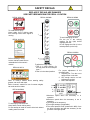
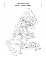
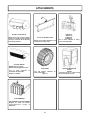
OWNER’S MANUAL
Model Number
700312-5
BERCO
Rotary Tiller
Universal mount for
YARD & GARDEN
Tractors
* ASSEMBLY
* REPAIR PARTS
* OPERATION
* MAINTENANCE
CAUTION:
READ & FOLLOW ALL SAFETY RULES & INSTRUCTIONS BEFORE
OPERATING YOUR EQUIPMENT
106111_EN
*106111*
1
M-02
LIMITED WARRANTY
Owner’s Responsibilities:
Conditions and Products Covered:
BERCOMAC guarantees any part of the product or accessory
manufactured by BERCOMAC and found in the reasonable
judgment of BERCOMAC to be defective in material and or
workmanship will be repaired or replaced by an authorized
dealer without charge up to our maximum labor rates and preestablished times. For replacement parts only standard ground
freight services are covered. This warranty extends to the
original retail purchaser only and is not transferable to any
subsequent purchasers. This warranty applies to the products
bought and used in North America.
BERCOMAC’s defective equipment or part must be returned
to an authorized dealer within the warranty period for repairs.
In the event that defective merchandise must be returned to
manufacturer for repairs, freight fees are prepaid and a written
authorization from BERCOMAC must be obtained by dealer
prior to the shipment. This warranty extends only to
equipment operated under normal conditions. To validate a
warranty claim, it is the user’s responsibility to maintain and
service the unit as specified in the owner’s manual or to have
the unit serviced at their dealer at their expense.
Warranty Period
(from date of the original retail purchase)
General Conditions:
The sole liability of BERCOMAC with respect to this warranty
shall be strictly and exclusively repair and replacement as
mentioned herein. BERCOMAC shall not have any liability for
any other costs, loss or damage, including but not limited to,
any incidental or consequential loss or damage.
Taking advantage of the warranty does not in any way extend
the length or renewal of the warranty.
• Residential use: 1 year
• Semi-commercial, professional or rental use: 90 days
Exceptions Noted Below; the following items are guaranteed
by the original manufacturer and have their own warranty,
conditions and limited time:
• Tire Chains: 90 days
• Engines: Will vary as per the manufacturer
Please refer to the engine manufacturer’s warranty
statement included with the unit. BERCOMAC is not
authorized to handle warranty adjustments on engines.
In particular, without being limited to, BERCOMAC shall have
no liability or responsibility for:
• Travel time, overtime, after hours time or other
extraordinary repair charges or relating to repairs and or
replacements outside of normal business hours.
• Rental of like or similar replacement equipment during the
period of any, repair or replacement work.
• Any communicating or travel charges.
• Loss or damage to person or property other than that
covered by the terms of this warranty.
• Any claims for lost revenue, lost profit or any similar costs
as a result of damage or repair.
• Attorney’s fees.
Items and Conditions NOT Covered:
This warranty does not cover the following:
• Pick-up or delivery charges or in-home services fees.
• Any damage or deterioration of the unit, parts and or finish
of these due to normal use, wear and tear, or exposure.
• Cost of regular use or maintenance service or parts, such as
gas, oil, lubricants, tune-up parts, and adjustments.
• Any part or accessory which has been altered, modified,
misused, neglected, accidentally damaged or not properly
installed, maintained, stored or repaired not in accordance
with the instructions in the owner’s manual.
• Repair due to normal wear and or any wear items such as
shear pins, bolts, belts, etc.
• Expedited freight fee services for replacement parts.
• Shear bolts and shear pins are to be considered as a
preventive measure not as an assured protection, any
damages resulting from the lack of shear bolts breakage are
not covered.
• Damages due to product being installed on a vehicle other
than stipulated in owner’s manual.
NOTE: All warranty work must be performed by an authorized
dealer using original (manufacturer) replacement parts.
BERCOMAC’s responsibility in respect to claims is limited to
making the required repairs or replacement without charge up
to our maximum labor rates and pre-established times and no
claim of breach of warranty shall be cause for cancellation or
rescission of the contract of sale of any product or accessory.
In no event recovery of any kind be greater than the amount of
the purchase price of the product sold.
This warranty gives you specific legal rights. You may also
have other rights, which vary from state to state.
NOTE: Bercomac reserves the right to change or improve the design of any part or accessory without assuming any obligation to modify
any product previously manufactured.
Instructions for Obtaining Warranty Services:
Contact dealer where equipment was purchased or any other BERCO service dealer to arrange service at their dealership. Requests for
warranty claims must be carried out through the same distribution network used to purchase the product.. Don't forget to bring your proof
of purchase (sales receipt) to the BERCOMAC dealer.
Bercomac Limitée
92, Fortin North, Adstock, Quebec, Canada, G0N 1S0
2
TABLE OF CONTENTS
PAGE
INTRODUCTION ...................................................................................................................................................
2
SAFETY PRECAUTIONS .....................................................................................................................................
3
SAFETY DECALS .................................................................................................................................................
5
ASSEMBLY
Overall View & Required Tools ...............................................................................................................
Step 1: Tractor Preparation ....................................................................................................................
Step 2: Rotary Tiller Preparation ............................................................................................................
Step 3: Rotary Tiller Installation, (Primary installation) ..........................................................................
Primary Belt Adjustment ............................................................................................................
Clutch Cable Installation ............................................................................................................
Verify the Rotary Tiller’s Secondary Belt Adjustment ...............................................................
Re-Installation ............................................................................................................................
6
7
9
12
13
14
15
16
OPERATION
Before Tilling ............................................................................................................................................
Operating the Rotary Tiller ......................................................................................................................
Transporting the Rotary Tiller ..................................................................................................................
Inspecting, Cleaning or Parking the Rotary Tiller ...................................................................................
18
18
19
19
MAINTENANCE
Belt Replacement ....................................................................................................................................
Primary Belt Adjustment ..........................................................................................................................
Secondary Belt Adjustment .....................................................................................................................
Maintenance ............................................................................................................................................
Replacing the Tines .................................................................................................................................
20
20
20
20
21
DISMOUNTING
Dismounting the Rotary Tiller ..................................................................................................................
End of Season Storage ...........................................................................................................................
22
22
TROUBLESHOOTING ..........................................................................................................................................
23
PARTS BREAKDOWN AND LISTS
Rotary Tiller (Frame) ...............................................................................................................................
Rotary Tiller (Head) .................................................................................................................................
24
28
TORQUE SPECIFICATION TABLE .....................................................................................................................
31
ATTACHMENTS ...................................................................................................................................................
32
1
INTRODUCTION
TO THE PURCHASER
This new accessory was carefully designed to give years of dependable service. This manual has been provided to
assist in the safe operation and servicing of your attachment.
NOTE: All photographs and illustrations in the manual may not necessarily depict the actual models or attachment, but
are intended for reference only and are based on the latest product information available at the time of publication.
Familiarize yourself fully with the safety recommendations and operating procedures before putting the machine to
use. Carefully read, understand and follow these recommendations and insist that they be followed by those who will
use this attachment.
THIS SAFETY ALERT SYMBOL IDENTIFIES AN IMPORTANT SAFETY MESSAGE IN THIS
MANUAL THAT HELPS YOU AND OTHERS AVOID PERSONAL INJURY OR EVEN DEATH.
DANGER, WARNING, AND CAUTION ARE SIGNAL WORDS USED TO IDENTIFY THE LEVEL OF
HAZARD. HOWEVER, REGARDLESS OF THE HAZARD, BE EXTREMELY CAREFUL.
DANGER:
Signals an extreme hazard that will cause serious injury or death if recommended precautions
are not followed.
WARNING:
Signals a hazard that may cause serious injury or death if the recommended precautions are
not followed.
CAUTION:
Signals a hazard that may cause minor or moderate injury if the recommended precautions are
not followed.
Record your attachment serial number and purchase date in the section reserved below (there is no serial number on
the subframe). Your dealer requires this information to give you prompt, efficient service when ordering replacement
parts. Use only genuine parts when replacements are required.
If warranty repairs are required please present this registration booklet and original sales invoice to your selling dealer
for warranty service.
This manual should be kept for future reference.
Please check if you have received all the parts for your kit with the list of the
bag and the list of the box.
SERIAL NUMBER :
___________________________
(IF APPLICABLE)
MODEL NUMBER:
___________________________
PURCHASE DATE :
___________________________
2
SAFETY PRECAUTIONS
Careful operation is your best insurance against an accident. Read this section carefully before operating the vehicle
and accessory. This accessory is capable of amputating hands and feet and throwing objects. Failure to observe the
following safety instructions could result in serious injury. All operators, no matter how experienced they may be,
should read this and other manuals related to the vehicle and accessory before operating. It is the owner's legal
obligation to instruct all operators in safe operation of the accessory.
GLOSSARY:
4. Handle fuel with care, it is highly flammable.
a) Use approved fuel container.
b) Never add fuel to a running engine or hot engine.
c) Fill fuel tank outdoors with extreme care. Never fill
fuel tank indoors.
d) Never fill containers inside a vehicle, or on a
truck or a trailer bed with a plastic liner. Always
place containers on the ground, away from your
vehicle, before filling.
e) When
practical,
remove
gas-powered
equipment from the truck or trailer and refuel it
on the ground. If this is not possible, then refuel
such equipment on a trailer with a portable
container, rather than from a gasoline
dispenser nozzle.
f) Keep the nozzle in contact with the rim of the
fuel tank or container opening at all times, until
refueling is complete. Do not use a nozzle lockopen device.
g) Replace fuel cap securely and wipe up spilled
fuel.
h) If fuel is spilled on clothing, change clothing
immediately.
In this manual, right and left sides are determined by
sitting on the seat of the vehicle facing forward.
In this manual, "accessories" means attachments
(snowblower, rotary broom, blade etc.) that you install
on the vehicle (lawn tractors, A.T.V. s etc).
TRAINING:
This symbol, "Safety Alert Symbol", is used
throughout this manual and on the
accessory’s safety labels to warn of the
possibility of serious injury. Please take
special care in reading and understanding
the safety precautions before operating the
vehicle and accessory.
1. Read this owner's manual carefully. Be thoroughly
familiar with the controls and proper use of the
vehicle and accessory. Know how to stop the unit
and disengage the controls quickly.
2. Never allow children to operate the vehicle nor the
accessory. Never allow adults to operate the vehicle
nor the accessory without proper instructions.
3. No one should operate the vehicle nor the
accessory while intoxicated or while taking
medication that impairs the senses or reactions.
5.
Never attempt to make any adjustments while the
engine (motor) is running (except when specifically
recommended by manufacturer).
6.
Let the vehicle and accessory adjust to outdoor
temperatures before using.
7.
Never use an accessory without proper guards,
plates, or other safety protective devices in place
8.
Always make sure to wear the appropriate safety
equipment required (glasses, muffs, mask…) for
each type of product. See operation section.
9.
Always make sure of having safe traction on the
vehicle by using the recommended accessories
(chains, A.T.V. tracks, counterweights…). See
operation section.
4. Keep the area of operation clear of all people,
particularly small children and pets.
PREPARATION:
1. Thoroughly inspect the area where the accessory
is to be used and remove door mats, all foreign
objects and the like.
2. For motorized accessories, disengage all clutches
and shift into neutral before starting engine.
10. Always make sure the all components are correctly
installed. (driveline securely attached and locked at
both ends, belts properly installed…)
3. Do not operate the accessory without wearing
adequate winter outer garments. Avoid loose fitting
clothing that can get caught in moving parts. Wear
footwear that will improve footing on slippery
surfaces.
11. Always handle the winch cable with thick leather
gloves.
12. Never modify the accessory or any part without
the written consent from the manufacturer.
3
SAFETY PRECAUTIONS
OPERATION:
MAINTENANCE AND STORAGE
1.
Do not put hands or feet near, under or inside rotating
parts.
2.
Exercise extreme caution when operating on or
crossing gravel drives, walks or roads. Stay alert for
hidden hazards or traffic. Do not carry passengers.
3.
After striking a foreign object, stop the engine (motor),
disconnect the wire from the spark plug(s) and keep
wire away to prevent accidental starting. Thoroughly
inspect the accessory for any damage and repair
damage before restarting and using the accessory.
4.
If the unit should start to vibrate abnormally, stop the
engine (motor) and check immediately for the
cause. Vibration is generally a warning of trouble.
5.
Take all possible precautions when leaving the
vehicle unattended. Disengage the power take-off,
lower the attachment, place the transmission into
neutral, set the parking brake, stop the engine and
remove the contact key.
6.
Do not run the engine indoors, except when starting
the engine and for transporting in or out of the
building. Do not operate or let motor run in a storage
area without ventilation because gas contains
carbon monoxide which is odorless, colorless and
can cause death.
7.
Never use the accessories across the face of
slopes, go from top to bottom. Exercise extreme
caution when using equipment on slopes. Do not
attempt to clear a steep slope.
8.
Never tolerate bystanders in the working zone.
Never use an accessory in the direction of
bystanders, it might throw gravel or debris that can
hurt people or damage property.
9.
Never operate the accessory at high transport
speeds on slippery surfaces. Use care when
backing up.
1.
When cleaning, repairing or inspecting the vehicle
and accessory, make certain that all moving parts
have stopped. For gasoline engine, disconnect wire
from the spark plug(s) and keep wire away to
prevent accidental starting.
2.
Check all the bolts and components at frequent
intervals to make sure that they are properly
tightened.
3.
Never store a motorized accessory with fuel in the
fuel tank inside a building where ignition sources are
present such as hot water and space heaters,
clothes dryers, and the like. Allow the engine to cool
before storing in any enclosure.
4.
Always refer to the owner’s manual when you store
the accessory and vehicle for a prolonged or an
unspecified length of time.
5.
Maintain or replace safety and instruction labels, as
necessary.
6
For winter accessories, (if applicable), let the engine
run for a few minutes after clean snow in order to
prevent the rotary parts from freezing.
7.
Inspect the vehicle’s and accessory’s air filter (if
applicable) every day. Clean it or replace it as
necessary. Change the oil more often when working
in dusty conditions. See the vehicle’s and
accessory's owner’s manual.
10. Do not carry passengers.
11. Disengage power to the accessory when it is
transported or not in use.
THIS SYMBOL MEANS
DANGER !
BECOME ALERT !
YOUR SAFETY IS INVOLVED !
12. Never operate the accessory without good visibility
or light.
13. Keep the accessory away from heat sources or
flames.
14. Never handle the winch cable or hook while in
tension.
4
SAFETY DECALS
REPLACE IF DECALS ARE DAMAGED
SEE PARTS BREAKDOWN FOR DECAL LOCATION
DECAL #105988
DECAL #105129
To avoid serious injury:
Keep hands, feet & clothing away
from rotating knives while engine is
running.
DECAL #105989
1
To avoid damaging the tiller:
Put the pin in the working
position (on the right) before
engaging the tiller.
Do not engage the tiller is in the
locked position (on the left).
DECAL #105130
DECAL #105990
Before installing or using:
Locate, read and make sure to
understand all of the owner’s
manual.
DECAL #105131
2
To adjust the tilling depth:
1.Tiller is in tilling position. On
the first pass do not till deeper
than 1’’.
2.Tiller is in the raised position.
Refer to owner’s manual about wearing safety
glasses, ear muffs and mask.
Refer to owner’s manual for use of counter weights,
cat tracks and tire chains.
1
2
3
For proper adjustment of the
secondary belt:
1. Adjusting nut: Turn the nut to
apply tension on the belt.
2. Not enough tension on belt.
Adjustment required.
3. Belt is well adjusted.
1
2
DECAL #105996
3
4
5
1-Maximum speed when the accessory is in
operation.
2-Maximum speed when the accessory is not in
operation.
3-The weight of the accessory.
4-The engine wattage (if applicable).
5-The sound pressure level (measured in dBA) from
the driver’s position and with the accessory on the
ground at full engine speed.
To avoid injury from drive belt:
Keep hands, feet & clothing away.
Do not attempt to install or remove drive belt without
reading owner’s manual.
5
ASSEMBLY
CONVERSION TABLE
1’’ (po, in)
25.4 mm
1’ (pi, ft)
0.3 m
2
GLOSSARY
Quad = V.T.T., A.T.V.
Véhicule tout terrain
V.T.T.
All terrain vehicle
A.T.V.
1 psi (lb/in )
6.89 kPa
1 lb
0.45 kg
1 lbf
4.4 N
Power take-off
(P.T.O)
1 m/h (mi/h)
1.61 km/h
Prise de force
(P.D.F)
1 hp (cv)
0.75 kW
P.T.O. = P.D.F
IMPORTANT: TORQUE ALL BOLTS ACCORDING TO TORQUE SPECIFICATION TABLE WHEN STATED:
TIGHTEN FIRMLY. REFER TO PARTS BREAKDOWN SECTION FOR PART IDENTIFICATION.
TOOLS REQUIRED:
Overall view
1 Jack
2 Axel stands
1 Pair of pliers
1 Flat screwdriver
5 Wrenches, 3/8", 7/16", 1/2", 9/16", 3/4"
1 Ratchet
3 Sockets 7/16", 1/2", 9/16"
1 Measuring tape
1 Drill
1 Bit 13/32"
6
ASSEMBLY
STEP 1
TRACTOR PREPARATION:
THIS ATTACHMENT IS A UNIVERSAL MOUNT.
THE MANUFACTURER DOES NOT GUARANTEE
THAT IT CAN BE SUCCESSFULLY INSTALLED
ON EVERY BRAND/MODEL OF TRACTOR. A
BELT SIZE OTHER THAN THE BELTS SUPPLIED
MAY BE NECESSARY.
WARNING
TO PREVENT INJURIES:
Stop the motor.
Apply parking brake.
Remove the ignition key.
Disconnect the wire from the spark plug(s) and
keep away from spark plug(s) to prevent accidental
starting.
Please refer to the Recommended Installation Chart
that is included for specific brands of tractors.
Remove the mower deck. See the tractor owner’s
manual for dismounting instructions.
Measure the height (item 1) between the tractor’s rear
tow hitch and the ground. This measurement is
needed for Step 2.
Block the front wheels of the tractor. Using a jack, lift the
rear end of the tractor and remove the wheels.
Block in place with an axle stand (item 4) under each
side.
Determine a set of bolt holes on the transaxle (item 3)
that measure 16 1/4” or 14" center to center in order to
bolt the mounting brackets.
If there are bolts (item 2) already installed, remove them.
Remove wheels and bolts
Tractors with parallel transaxle
For tractors with a set of holes on the transaxle that
measure 16 1/4" center to center.
Install the mounting brackets (item 1) with the 90°
corner (item 4) towards the front of the tractor and
towards the center of the tractor as shown.
For Cub Cadet tractors use brackets (item 5).
NOTE: If the distance between the bottom of the
transmission and the bolts is less than 2 1/4’’ (as
shown) you do not need the sleeves.
If needed, shim with flat washers or sleeves (items 2 or
3) between the mounting brackets and the transaxle so
that the mounting brackets are parallel with the
transmission.
Secure with the 5/16" x 3 1/2" or 5/16" x 4" hex bolts
and nuts as shown.
Do not tighten.
NOTE: If your tractor is equipped with 3/8" n.c. hex.
bolts, drill the holes in the mounting brackets (item 1) to
13/32" diamater and use the hex. bolts 3/8" x 5" and
nuts as shown .
Do not tighten.
View of back of tractor
Install mounting brackets
View of back of tractor
Install these mounting brackets
on the Cub Cadet 2000-2500
7
ASSEMBLY
For tractors with a set of holes on the transaxle that
measure 14" center to center.
Install the mounting supports (item 1), the holes (item 2)
towards the back and towards the center of the tractor.
If necessary , reverse the position of the supports in
order to be able to bolt on the transmission.
Secure with the 5/16" x 3 1/2" or 5/16" x 4" hex bolts and
nuts.
NOTE: If your tractor is equipped with 1/2" bolts, use
these bolts in the holes (item 3) on the mounting
brackets.
Do not tighten.
NOTE:
If there is less than 6’’ between the rear bolts of the
transaxle and the hole on the rear tow hitch, turn the
mounting brackets (item 3) 180° (holes item 2, towards
the front) and install the brackets with the holes towards
the inside of the tractor.
There must be a distance of 12 1/4’’ center to center
between the holes (item 2).
View of back of tractor
Install mounting brackets
Tractors with angled transaxle:
Install the mounting brackets (item 2), the angled end
towards the front of the tractor and the hole (item 4)
towards the center of the tractor as shown.
If needed, shim with flat washers (item 3) between the
mounting brackets and the transaxle so that the
mounting brackets are parallel with the transaxle.
Secure with the appropriate length bolts and nuts as
shown.
Do not tighten.
View of back of tractor
Install mounting brackets
8
ASSEMBLY
STEP 2
ROTARY TILLER PREPARATION
Determine the set of holes (item 1) to use to attach the
tiller’s hitch (item 2) by using the following chart:
NOTE: If you have used the short sleeves to install
the mounting supports, install the tiller hitch (item 2) in
one set of holes higher than which is mentioned in
the chart.
If you have used the long sleeves to install the
mounting supports, install the tiller hitch (item 2) in
two set of holes higher than which is mentioned in the
chart.
*Measurement from the
ground to the tow hitch
Sets holes
(see figure)
7.00" to 7 5/8’’
8th
7 5/8’’ to 8 1/4"
7th
8 1/4" to 8 7/8"
6th
8 7/8" to 9 1/2"
5th
9 1/2" to 10 1/8"
4th
10 1/8" to 10 3/4"
3rd
10 3/4" to 11 3/8"
2nd
11 3/8" to 12"
1st
Attach the tiller’s hitch
*These measurements are given as a reference only.
After installing the rotary tiller, the frame should be 4
1/2" to 5 1/2" off the ground.
Note: If the tiller’s frame touches the back of the tractor
or the wheels, you may add one to four shims (item 3)
between the tiller’s back wall and the tiller hitch (item 2).
If using more than two shims, use the 3/8 x 2" hex bolts.
Verification: Make sure the tiller’s frame will pass under
the transaxle when dismounting the tiller.
9
ASSEMBLY
Install the lift arm (item 1) with four 5/16 x 3/4" bolts
(item 2) and flange nuts.
Install the lift arm
For Installation Purposes Only:
Remove the pin (item 1) from the working position and
insert it in the locked position (item 2). Secure in place
with a hair pin (item 3).
IMPORTANT:
To avoid damage to the tiller, never use tiller with
pin in locked position.
Working Position
Locked Position
Move the pin to locked position
10
ASSEMBLY
NOTE: If the tractor is equipped with a transmission
that has a distance between the bolts of 14",
interchange the mounting pins (item 2 on the left
side and item 3 on the right side) to get a distance of
12 1/4’’ center to center between the pins.
Loosen the square head set screw (item 1) that holds
the mounting pins (right and left) (items 2 & 3).
Slide the mounting pins towards the back of the frame.
Unscrew and remove the hitch pin (item 4).
Prepare the pins
Prepare the adjusting link as shown.
Apply some grease on the adjusting rod (item 1).
Insert the two nuts (item 2) on the adjusting rod and
screw to the middle.
Install the two links (item 3) on each end of the adjusting
rod.
NOTE: In some cases it may be necessary to cut the
adjusting rod (item 1).
Insert a flange nut (item 5) (head first) on the bolt (item
6) and screw down to the end of the threads as shown
(item 4).
For the Cub Cadet 2000 and 2500 series: Items 4,5
and 6 are not required.
You will be using the 5/16’’ x 1 1/4’’ hex bolt and 5/16’’
nut and a 3/8’’ x 1’’ hex bolt and nut.
Prepare the adjusting link
11
ASSEMBLY
STEP 3
ROTARY TILLER INSTALLATION:
(Primary installation)
Lower the lift arm to place the rotary tiller’s frame flat on
the ground. Slide the rotary tiller under the tractor.
Lower the lift arm (item 1) until it locks in the "UP"
position (item 2) to lift the front portion, then lower the
support (item 3) so that it supports the rotary tiller frame.
Raise the lift arm until the rotary tiller’s hitch (item 4) is
even with the tractor’s tow hitch. Slide the rotary tiller
hitch onto the tractor’s tow hitch (the holes must be
aligned). Secure by screwing the hitch pin (item 5)
firmly.
Line up the rotary tiller’s frame with the tractor’s frame.
Lift and slide the mounting pins (item 6) into the
mounting bracket’s holes (item 7) (on both sides,
previously installed on transaxle).
NOTE: If the tractor is equipped with a transmission that
is bolted at 14” center to center, interchange the
mounting pins.
Install the tiller to tractor
Lightly tighten the square head screws on the mounting
brackets (item 8).
To install the adjustable link, locate a hole or if
necessary, drill a hole in the tractor’s frame directly
above the hole on the tiller’s frame as shown.
Note: Check the primary belt alignment before drilling
the hole. Make sure the mower supports do not touch
the rotary tiller’s pulley.
Install the special bolt (item 1) from the outside of the
frame and secure in place with a flange nut (on the
inside of the tractor frame). Tighten firmly. Do the same
on the rotary tiller’s frame.
Attach the link (item 2) on the bolts (item 1) installed.
Secure with two 2.5 mm. hair pins (item 3).
NOTE: If here is too much space between the link and
the frame , add eight flat washers 3/8" (item 4) before
inserting the 2.5mm hair pins as shown.
For the Cub Cadet 2000 and 2500 series:
Remove the bolt from the tractor frame and install the
link with the 5/16’’ x 1 1/4’’ hex bolt and 5/16’’ nut
(head first) to secure the top part of the link on the
tractor frame.
Use the 3/8’’ x 1’’ hex bolt and nut (head first) to
secure the bottom part of the link on the rotary tiller
frame.
Install the adjustable link
12
ASSEMBLY
Please refer to the Recommended Installation Chart
that is included specific brands of tractors.
Note: Choose the appropriate belt among the ones
supplied. However, the rotary tiller being a universal
mounting, a belt size other than the ones supplied
may be necessary.
Install the primary belt (item 1) on the engine pulley
(item 2), flat pulley (item 3) and the pulley on the tiller
(item 4).
Lift or lower the front part of the rotary tiller with the
adjustable link (item 5) so that the belt is aligned with
the pulleys as shown.
Install primary belt
NOTE: If the belt is not aligned with the pulleys, remove
the nut (item 6) and add a few 3/8” flat washers (item 7)
between the flat pulley and the tension arm (item 8).
Make sure the belt is centered on the flat pulley.
Secure with the nut.
Tighten the nuts on the links very firmly.
Lift the support (item 9).
Make sure both sides of the rotary tiller’s frame (item 1)
are at the same height from the ground.
Tighten firmly the bolts that hold the mounting brackets
to the transaxle.
Tighten the square head set screws (item 2) very firmly
on the mounting pins (both sides of tractor).
TIP: To make sure the frame is even, the bottom portion
(item 3) of the mounting pins must measure equally on
both sides. Tire pressure in both rear tractor tires must
be identical.
Tighten the screws
PRIMARY BELT ADJUSTMENT
Tractors with an electric clutch mechanism:
Adjust the tension on the primary belt by loosening the
square head set screw (item 1). Pull the tension rod
(item 2) to stretch the spring (item 3) by 3/4" to 1".
Tighten the square head screw securely.
NOTE: If more tension is necessary, move the 1/4" x
3/4" (item 4) and the nut (item 5) into the second hole
(item 6) in the tension bar.
Adjust tension
13
ASSEMBLY
CLUTCH CABLE INSTALLATION
Tractors with manual clutch mechanism:
Disengage the clutch:
If your cable (item 1) does not have a spring at the end,
attach the cable to the spring (item 3) on the tiller and
attach the cable on the adjustable tension rod (item 2).
Secure in place.
Note: The tension rod (item 2) can be adjusted or
inverted (as shown) to accommodate the length of the
cable.
Note: If you have a cable with a spring at the end, go to
the next step.
Install cable
If your clutch cable has a spring at the end, you must
remove the original spring from the tiller.
Attach the cable’s spring (item 1) to the extension bar
(item 2). Attach the cable shield on the tension rod (item
3) and secure in place with a hair pin.
Note: The tension rod can be adjusted or rotated to
accommodate the length of the cable.
Install spring
Install the spring (item 2) that releases the tension on
the belt, the short hook in the idler arm (item 3) and the
long hook on the rod (item 4).
Adjust the cable when the clutch is engaged. The spring
(item 5) should be stretched to approx. 3/4" to 1"
Install the stopper (item 1) with a 5/16 x 3/4" bolt, flat
washer on the slot and flange nut. Adjust the stopper in
order to be sure the belt does not fall off the engine
pulley when the P.T.O. is disengaged. However, the belt
must be loose enough to allow tiller to stop turning
immediately when P.T.O. is disengaged.
OPTION
If your tractor does not have a clutch cable or the cable
is too short, a "clutch mechanism kit" under model
number #700319 is available as an option.
Install spring and stopper
14
ASSEMBLY
VERIFY THE ADJUSTMENT OF THE ROTARY
TILLER’S SECONDARY BELT:
When the belt is correctly adjusted, you should barely
see the hole in the tension gauge (item 1).
If the hole is exposed (item 2), readjust the belt by
screwing the nut (item 3) until well adjusted (item 1).
Adjustment
Requires
adjustment
Well adjusted
Adjust tension
Reinstall the rear wheels on the tractor.
Move the lift arm (item 1) to the hole (item 2) identified
"0".
Loosen the bolt (item 3) and slide it down in the slot till it
touches the lift arm (item 4).
Tighten firmly.
Remove the pin (item 5) from the locked position and
install it in the working position.
Secure with the hair pin.
Raise the rotary tiller and let it run under supervision.
Make sure everything is running smoothly and that both
V belts do not touch the belt guides.
Last adjustments
15
ASSEMBLY
RE-INSTALLATION:
WARNING
TO PREVENT INJURIES:
Stop the motor.
Apply parking brake.
Remove the ignition key.
Disconnect the wire from the spark plug(s) and
keep away from spark plug(s) to prevent accidental
starting.
On a level surface remove the mower deck from tractor.
Remove the pin (item 1) from the working position and
install it in the locked position. Secure with the hair pin.
(see next page).
Place the rotary tiller’s frame flat on the ground by
lowering the lift arm.
Slide the rotary tiller under the tractor.
Lower the lift arm (item 2) until it locks into the "UP"
position (item 3) to lift the front portion then lower the
support (item 4) to rest the tiller’s frame on the ground.
Raise the lift arm until the rotary tiller’s hitch (item 5) is
even with the tractor’s tow hitch. Slide the rotary tiller
hitch onto the tractor’s tow hitch (the holes must be
aligned) and make sure the mounting pins (item 7) slide
into the mounting bracket’s holes (both sides left on
tractor frame).
Secure by screwing firmly the hitch pin (item 6).
Install the link (item 8) on the special bolt left on the
tractor.
Secure with a 2.5 mm hair pin.
Re-installation
16
ASSEMBLY
Install the drive belt (item 1) on the engine pulley (item
2).
Lift the support (item 3).
If your tractor is equipped with a manual clutch, install
the spring (item 4) at the end of cable to the extension
bar (Item 5). Attach the cable shield to the adjustable
tension rod (item 6).
Secure in place with a hair pin.
Install belt and cable
Raise the tiller and remove the pin (item 7) from locked
position and insert it in the working position (item 8)
inside of the plate.
Secure with a hair pin (item 9).
Locked position
Working position
Move the pin to working position
17
OPERATION
CAUTION
IMPORTANT
TO PREVENT INJURIES:
-Remove all objects and keep people away from
the working area.
-Never let children operate the rotary tiller or
tractor.
-Never let children ride on the tractor or rotary
tiller.
-Never operate the rotary tiller without the guards
and shields in place.
-Wearing ear muffs, a dust mask and safety
glasses are recommended.
AVOID DAMAGE TO THE ROTARY TILLER
Never back up or make sharp turns with the
rotary tiller in the ground.
When breaking ground, it is recommended to till in
two to four stages. The first pass should be tilled at a
shallow depth then progressively deeper with each
pass.
When only a small area is to be tilled, make a pass
through the middle, then circle the pass going
towards the outside.
WARNING
Whenever possible, till straight ahead, tilling in circles
will leave ridges.
TO PREVENT INJURIES AND FOR MORE
TRACTION WITH ACCESSORY:
-Do not drive faster than 3 km/hr (2 m/hr) with the
accessory on the ground.
-Do not drive faster than 10 km/hr (6 m/hr) with
the accessory in raised position.
-Do not operate on a slope greater than 10°.
OPERATING THE ROTARY TILLER
CAUTION
TO PREVENT INJURIES
Tiller may push the tractor forward when tilling in
firm soil and on grass.
Make sure the tractor’s brakes are functional.
Always make sure the engaging system is
functional. If it is not the case, make the required
adjustments.
If the tractor is equipped with a manual clutch,
always stop the tractor’s engine before leaving
the driver’s seat.
BEFORE TILLING:
-Mow the grass and weeds before tilling, these can wrap
around the tines or tine shaft.
-Remove all objects that can damage the rotary tiller
such as rocks, branches, etc…
-Check the tines before tilling. Repair or replace any
loose, bent or broken tines.
-Do not till when the ground is too wet (if the soil forms a
ball in your hand when squeezed). The wet soil will
stick to the tines and tine shaft.
-Push the throttle lever to the medium position.
-Disengage the parking brake.
-Put the P.T.O. control in the ON position to engage the
rotary tiller. (See tractor’s owner’s manual for
instructions).
-Lower the tiller and adjust the tilling depth to 1" or
deeper after first pass.
-Engage the transmission in first gear or move forward
slowly if the tractor has a hydro transmission.
-Till the ground at a shallow depth and at slow traveling
speed (3km/h max.)
18
OPERATION
TRANSPORTING THE ROTARY TILLER:
Always lift the rotary tiller off the ground by lowering the
lift arm as far as it will go and disengage the accessory
when moving from one tilling area to another.
Drive at a safe traveling speed (max 10km/h) when the
tiller is off the ground because of the extra weight due to
the rotary tiller, the tractor is unbalanced.
Drive slowly on slopes and rough ground. Even with
front weights, it is dangerous to climb slopes greater
than 10%.
Never work across the face of a slope
INSPECTING, CLEANING OR PARKING THE
ROTARY TILLER
CAUTION
TO PREVENT INJURIES
Always stop the engine and wait for all moving
parts to stop before leaving the driver’s seat to
avoid injuries from the tines.
WARNING
TO PREVENT INJURIES:
Stop the motor.
Apply parking brakes.
Remove the ignition key.
Disconnect the wire from the spark plug(s) and
keep away from spark plug(s) to prevent accidental
starting.
Lower the tiller to the ground.
19
MAINTENANCE
WARNING
PRIMARY BELT ADJUSTMENT
Tractors with an electric clutch mechanism:
Adjust the tension on the front belt by loosening the
square head set screw (item 10). Pull the adjustable
tension rod (item 11) to stretch the spring by 3/4" to 1".
Tighten the screw securely.
TO PREVENT INJURIES:
Stop the motor.
Apply parking brake.
Remove the ignition key.
Disconnect the wire from the spark plug(s) and
keep away from spark plug(s) to prevent accidental
starting.
Never work under the vehicle nor under the
accessory.
Tractors with a manual clutch mechanism:
Adjust the cable so that the spring is stretched by 3/4" to
1" when the clutch mechanism is engaged.
BELT REPLACEMENT:
Primary belt:
-Remove the belt from engine pulley.
-Remove the bolt (item 1) that holds the idler (item 2).
-Remove the belt (item 3) and reinstall the new one on
the double pulley (item 7) as shown.
-Reinstall the idler (item 2) and belt guide (item 4) in the
same manner as removed. Make sure the belt guide is
90° with the idler arm.
-Reinstall the belt on the engine pulley.
SECONDARY BELT ADJUSTMENT
When the belt is correctly adjusted, you should barely
see the hole in the tension gauge (item 1).
If the hole is exposed (item 2), adjust the belt by
screwing the nut (item 3) until well adjusted.
Adjustment
Requires
adjustment
Well adjusted
Replace belts
Adjust tension
Secondary Belt:
-Unscrew the belt tension nut (item 5).
-Remove the bolt (item 6) and remove the double
pulley (item 7).
-Remove the belt guard (item 9).
-Remove the belt (item 8) and install the new one.
Make sure it is routed as shown.
-Reinstall as dismounted by reversing the steps.
-Screw the tension nut to adjust the V-belt until you
barely see the hole in the tension gauge.
-See secondary belt adjustment instructions
MAINTENANCE
After every hour:
-Remove trash from the tines if necessary.
-Make sure the engaging system is functional.
After every 4 hours:
-Check belt tension
-Adjust if needed
-Clean under the belt.
After every 8 hours or once a year:
-Grease the tiller drive shaft.
-Check mounting bolts at frequent intervals for proper
tightness in order to prevent costly repairs. Make sure
your rotary tiller is in good working condition.
Secondary belt
20
MAINTENANCE
REPLACING THE TINES
CAUTION
WARNING
TO PREVENT INJURIES:
Always safely block the tiller. Never work under
the tractor nor under the accessory.
TO PREVENT INJURIES:
Stop the motor.
Apply parking brake.
Remove the ignition key.
Disconnect the wire from the spark plug(s) and
keep away from spark plug(s) to prevent accidental
starting.
Note: To facilitate replacing the tines, you must remove
the tiller from the tractor and turn it upside down.
-Park the tractor safely.
-Raise the tiller as high as it will go and put some blocks
under the tiller.
Note: Each group of tines must have two left tines and
two right tines.
Left group of tines
For reference purposes:
-Alternate left and right tines in each group.
-A bolt with no spacer is 3/8 x 1 1/4" long.
-A bolt with one spacer is 3/8 x 1 3/4" long.
-A bolt with two spacers is 3/8 x 2 1/4" long.
LEFT GROUP OF TINES:
Remove the nuts (item 1), bolts (item 2) spacers (item
3), two left tines (4) and two right tines (item 5).
Install the new tines with same hardware in exactly the
same position as the old ones were installed.
MIDDLE GROUP OF TINES:
Remove the nuts (item 6), bolts (item 7), spacers (item
8), two left tines (item 9) and two right tines (item 10).
Install the new tines with same hardware in exactly the
same position as the old ones were installed.
Middle group of tines
RIGHT GROUP OF TINES:
Remove the nuts (item 11), bolts (item 12) spacers (item
13), two left tines (item 14) and two right tines (item 15).
Install the new tines with same hardware in exactly the
same position as the old ones were installed.
Right group of tines
21
DISMOUNTING
DISMOUNTING THE ROTARY TILLER
END OF SEASON STORAGE:
a) Clean the rotary tiller.
WARNING
b) Check the belts.
TO PREVENT INJURIES:
Stop the motor.
Apply parking brake.
Remove the ignition key.
Disconnect the wire from the spark plug(s) and
keep away from spark plug(s) to prevent accidental
starting.
c) Replace damaged or worn parts.
d) Paint scratched surfaces to prevent rust.
e) Lubricate the grease points.
f)
On a level surface, park the tractor and apply the
parking brake.
a) Install the pin (item 1) in the locked position.
b) Lower the tiller to the ground.
c) Remove the V-belt from the engine pulley (item 9).
d) Disconnect the clutch cable if installed.
e) Lower the front support (item 4).
f)
Remove the link (item 8) from the tractor frame.
g) Raise the tiller’s lift arm (item 2) to support the tiller
frame.
h) Unscrew the pin (item 6) from the hitch.
i)
Pull out the tiller from the tractor hitch.
j)
Using the lift arm, lower the tiller to the ground and
raise the front support.
k) Place the lift arm so the tiller rests flat on the
ground.
l)
Slide out the tiller from the tractor.
22
Store the tiller on a hard level surface in a clean,
dry place. If tiller must stay outside, wrap it in a
waterproof cover.
TROUBLESHOOTING
* Please refer to parts breakdown section for parts identification.
PROBLEM
Tiller will not turn.
Tiller operates irregularly.
POSSIBLE CAUSES
CORRECTIVE ACTION
Belt is damaged.
Replace the belt.
Belt is broken.
Replace the belt.
Belts are loose.
Tighten belts.
Belts are damaged.
Replace belts.
A group of tines may be packed up.
Remove any debris from the tines.
Till at a slow steady speed.
Make more than one pass. Start by
shallow pass then gradually deeper.
Replace damaged or bent tines.
Tiller is noisy or bouncing at the Tines are damaged or too many Replace bent or damaged tines.
back of tractor.
rocks.
Remove any rocks from tilling area.
23
PARTS BREAKDOWN
ROTARY TILLER (FRAME)
24
PARTS LIST
ROTARY TILLER (FRAME)
Ref.
Réf.
English description
Description française
Qty.
Qté.
Part #
Pièce #
1
Frame
Châssis
1
103436
2
Hitch
Attache
1
103437
3
Hitch pin
Goupille d'attache
1
103438
4
Belt guard
Garde-courroie
1
103439
5
Spacer
Douille
1
103429
6
Support
Support
1
103440
7
Flat pulley
Poulie plate
1
102765
8
Spacer
Espaceur
1
102241
9
Spring
Ressort
1
102892
10
Mounting plate
Plaque de montage
1
103441
11
Flange washer
Rondelle à bride
2
102081
12
Spring
Ressort
1
102152
13
Idler arm
Bras de tension
1
103442
14
Idler arm
Bras de tension
1
103443
15
Belt guide
Guide-courroie
1
102840
16
Flat pulley
Poulie plate
2
102839
17
Spacer
Espaceur
1
102753
18
Ball bearing
Roulement à billes
2
102736
19
Clamp
Crampe
2
103445
20
Right mounting pin
Goupille de montage droite
1
103446
21
Left Mounting pin
Goupille de montage gauche
1
103447
22
Right mounting bracket
Support de montage droit
1
103448
23
Left mounting bracket
Support de montage gauche
1
103449
24
Shim
Cale
4
103450
25
Extension bar
Barre d'extension
1
103444
26
Double pulley inc. 102736 & 102782
Poulie double inc.102736 & 102782
1
103416
27
Sleeve
Douille
1
102782
28
Spring
Ressort
1
102861
29
Sleeve
Douille
1
102418
30
Arm
Bras
1
103451
O/L = Obtain Locally
25
PARTS LIST
ROTARY TILLER (FRAME)
Ref.
Réf.
English description
Description française
Qty.
Qté.
Part #
Pièce #
31
Pin-lock
Goupille de barrure
1
103398
32
Spring
Ressort
1
102868
33
Lift mechanism
Mécanisme de relevage
1
103452
34
Cable shield
Gaine de câble
1
104304
35
Cable
Câble
1
104305
36
Handgrip
Poignée
1
103453
37
Lever w/104304 - 104305 - s. screw
Levier a/104304 - 104305 - v. pression
1
104306
38
Lift arm
Bras de relevage
1
103454
39
V-belt, B-99 (sb)
Courroie en v, B-99 (sb)
1
103414
40
V-belt, A-53
Courroie en v, A-53
1
103400
41
Left Bracket
Plaque de fixation gauche
1
103456
42
Nylon bushing
Coussinet en nylon
1
103087
43
Spring 1/2"
Ressort 1/2"
1
102003
44
Spring
Ressort
1
102304
45
Adjustable tension rod
Tige de tension ajustable
1
103457
46
Special bolt
Boulon spécial
2
103458
47
Link
Lien
2
103459
48
Adjusting rod
Tige d'ajustement
1
103460
49
Spacer
Douille d'espacement
4
103463
50
Hair pin 2.5mm
Goupille à ressort 2.5mm
2
102013
51
Spacer
Douille
1
103461
52
Sleeve
Douille
1
102322
53
Tension gauge
Indicateur de tension
1
103462
54
Stopper
Butée
1
103486
55
V-belt, A-58
Courroie en v, A-58
1
103518
56
V-belt, A-62
Courroie en v, A-62
1
104299
57
V-Belt , A-56
Courroie en V , A-56
1
104848
58
V-Belt , B-118
Courroie en V , B-118
1
104044
59
Right mounting bracket
Support de montage droit
1
104581
60
Left mounting bracket
Support de montage gauche
1
104582
O/L = Obtain Locally
26
PARTS LIST
ROTARY TILLER (FRAME)
Ref.
Réf.
English description
Description française
Qty.
Qté.
Part #
Pièce #
61
Spacer
Douille d'espacement
4
104583
62
Hex. socket set screw 1/4" n.c. x 1/4"
Vis à pression hex. 1/4" n.c. x 1/4"
2
O/L
63
Hex. bolt 1/4" n.c. x 3/4"
Boulon hex. 1/4" n.c. x 3/4"
1
O/L
64
Hex. bolt 1/4" n.c. x 1 3/4"
Boulon hex. 1/4" n.c. x 1 3/4"
1
O/L
65
Hex. bolt 5/16" n.c. x 3/4"
Boulon hex. 5/16" n.c. x 3/4"
5
O/L
66
Hex. bolt 5/16" n.c. x 1 1/4"
Boulon hex. 5/16" n.c. x 1 1/4"
1
O/L
67
Hex. bolt 5/16" n.c. x 1 3/4"
Boulon hex. 5/16" n.c. x 1 3/4"
1
O/L
68
Hex. bolt 5/16" n.c. x 3 1/2"
Boulon hex. 5/16" n.c. x 3 1/2"
4
O/L
69
Hex. bolt 5/16" n.c. x 4"
Boulon hex. 5/16" n.c. x 4"
4
O/L
70
Hex. bolt 3/8" n.c. x 3/4"
Boulon hex. 3/8" n.c. x 3/4"
2
O/L
71
Hex. bolt 3/8" n.c. x 1"
Boulon hex. 3/8" n.c. x 1"
3
O/L
72
Hex. bolt 3/8" n.c. x 1 1/4"
Boulon hex. 3/8" n.c. x 1 1/4"
4
O/L
73
Hex. bolt 3/8" n.c. x 2"
Boulon hex. 3/8" n.c. x 2"
6
O/L
74
Hex. bolt 3/8" n.c. x 2 1/4"
Boulon hex. 3/8" n.c. x 2 1/4"
1
O/L
75
Hex. bolt 3/8" n.c. x 3"
Boulon hex. 3/8" n.c. x 3"
1
O/L
76
Hex. bolt 3/8'' n.c. x 5''
Boulon hex. 3/8'' n.c. x 5''
4
O/L
77
Hex. bolt 5/8" n.c. x 5 1/2"
Boulon hex. 5/8" n.c. x 5 1/2"
1
O/L
78
Square head set screw 3/8" x 1/2"
Vis à pression à tête carré 3/8" x 1/2"
3
O/L
79
Flange nut 3/8" n.c.
Écrou à bride 3/8" n.c.
15
O/L
80
Flange nut 5/16" n.c.
Écrou à bride 5/16" n.c.
6
O/L
81
Hex. nut 1/2" n.c. (thin)
Écrou hex. 1/2" n.c. (mince)
2
O/L
82
Nylon insert lock nut 5/16" n.c.
Écrou à garniture de nylon 5/16" n.c.
6
O/L
83
Nylon insert lock nut 3/8" n.c.
Écrou à garniture de nylon 3/8" n.c.
6
O/L
84
Nylon insert lock nut 1/4" n.c. (thin)
Écrou à garniture de nylon 1/4" n.c. (mince)
2
O/L
85
Nylon insert lock nut 5/8" n.c.
Écrou à garniture de nylon 5/8" n.c.
1
O/L
86
Flat washer 11/16" hole
Rondelle plate 11/16" trou
1
O/L
87
Flat washer 3/8" hole
Rondelle plate 3/8" trou
31
O/L
88
Tie wrap 7"
Attache de nylon 7"
2
O/L
89
Decal depth
Décalque profondeur
1
105988
90
Decal belt adjustment
Décalque ajustement de la courroie
1
105990
91
Decal miniature danger belts
Décalque miniature danger courroies
1
105996
O/L = Obtain Locally
27
PARTS BREAKDOWN
ROTARY TILLER (HEAD)
28
PARTS LIST
ROTARY TILLER (HEAD)
Ref.
Réf.
English description
Description française
Qty.
Qté.
Part #
Pièce #
1
Frame
Châssis
1
103417
2
Tine shaft
Arbre des dents
1
103418
3
Left tine
Dent gauche
8
103419
4
Right tine
Dent droite
8
103420
5
Spacer
Douille
12
103421
6
Drive shaft
Arbre d'entrainement
1
103422
7
Sprocket assembly
Pignon assemblé
1
103423
8
Chain guard
Garde-chaîne
1
103424
9
Deflector
Déflecteur
1
103425
10
Rod
Tige
1
103426
11
Roller chain #50 x 66 links/conn. link
Chaîne #50 x 66 mailles/maille acc.
1
103427
12
Connecting link #50
Maille d'accouplement #50
1
104324
13
Flangette
Flangette
1
102680
14
Bearing with collar and set screw
Roulement à billes avec collet & vis à pres.
2
103466
15
Dust cover
Protège poussière
2
103428
16
Flangette
Flangette
2
102213
17
Shim washer
Rondelle d'espacement
1
103430
18
Seal
Joint d'étanchéité
1
103431
19
Needle bearing
Roulement à aiguilles
2
103465
20
Spring
Ressort
1
103291
21
Key 3/16" x 3/16" x 1.000"
Clé 3/16" x 3/16" x 1.000"
1
102379
22
Pin
Goupille
1
102188
23
Hair pin 3mm
Goupille à ressort 3mm
1
102617
24
V pulley
Poulie en V
1
103415
25
Tensioner
Tensionneur
1
103289
26
Seal
Joint d'étanchéité
1
104586
27
Grease fitting 1/4" n.f.
Graisseur 1/4" n.f.
1
O/L
O/L = Obtain Locally
29
PARTS LIST
ROTARY TILLER (HEAD)
Ref.
Réf.
English description
Description française
Qty.
Qté.
Part #
Pièce #
28
Cotter pin 5/32" x 1"
Goupille fendue 5/32" x 1"
1
O/L
29
Carriage bolt 1/4" n.c. x 5/8"
Boulon à carrosserie 1/4" n.c. x 5/8"
10
O/L
30
Carriage bolt 5/16" n.c. x 1 1/4"
Boulon à carrosserie 5/16" n.c. x 1 1/4"
4
O/L
31
Hex. socket set screw 5/16" n.c. x 5/16"
Vis à pression hex. 5/16" n.c. x 5/16"
2
O/L
32
Hex. bolt 3/8" n.c. x 3/4"
Boulon hex. 3/8" n.c. x 3/4"
1
O/L
33
Hex. bolt 3/8" n.c. x 1"
Boulon hex. 3/8" n.c. x 1"
2
O/L
34
Hex. bolt 3/8" n.c. x 1 1/4"
Boulon hex. 3/8" n.c. x 1 1/4"
6
O/L
35
Hex. bolt 3/8" n.c. x 1 3/4"
Boulon hex. 3/8" n.c. x 1 3/4"
8
O/L
36
Hex. bolt 3/8" n.c. x 2 1/4"
Boulon hex. 3/8" n.c. x 2 1/4"
2
O/L
37
Hex. bolt 7/16" n.c. x 2" GR8
Boulon hex. 7/16" n.c. x 2" GR8
2
O/L
38
Hex. bolt 1/2" n.c. x 3/4"
Boulon hex. 1/2" n.c. x 3/4"
1
O/L
39
Flange nut 1/4" n.c.
Écrou à bride 1/4" n.c.
10
O/L
40
Flange nut 3/8" n.c.
Écrou à bride 3/8" n.c.
1
O/L
41
Flange nut 5/16" n.c.
Écrou à bride 5/16" n.c.
4
O/L
42
Nylon insert lock nut 3/8" n.c.
Écrou à garniture de nylon 3/8" n.c.
18
O/L
43
Nylon insert lock nut 7/16" n.c.
Écrou à garniture de nylon 7/16" n.c.
2
O/L
44
Nylon insert lock nut 5/16" n.c.
Écrou à garniture de nylon 5/16" n.c.
4
O/L
45
Lock washer 1/2"
Rondelle de blocage 1/2"
1
O/L
46
Decal warning safety
Décalque avertissement sécurité
1
105131
47
Decal important
Décalque important
1
105989
48
Berco decal
Décalque Berco
1
102471
49
Decal danger tines
Décalque danger dents
1
105129
50
Decal read instructions
Décalque lire instructions
1
105130
51
Made in Canada decal
Décalque Fabriqué au Canada
1
REF
52
Specifications decal
Décalque spécifications
1
REF
53
Serial number
Numéro de série
1
REF
O/L = Obtain Locally
30
TORQUE SPECIFICATION TABLE
GENERAL TORQUE SPECIFICATION TABLE
USE THE FOLLOWING TORQUES WHEN SPECIAL TORQUES ARE NOT GIVEN
NOTE: These values apply to fasteners as received from supplier, dry or when lubricated with normal oil. They do not
apply if special graphited or moly disulphide greases or other extreme pressure lubricants are used. This applies to
both UNF and UNC threads.
* Thick nuts must be used with grade 8 bolts
SEE Grade No.
BOLT HEAD
IDENTIFICATION
MARKS AS PER GRADE
NOTE MANUFACTURING
MARKS W ILL VARY
BOLT SIZE
Inches
2
5
8*
TORQUE
TORQUE
TORQUE
FOOT POUNDS
Millimetre
NEW TON-METERS
FOOT POUNDS
NEW TON-METERS
FOOT POUNDS
NEW TON-METERS
Min.
Max.
Min.
Max.
Min.
Max.
Min.
Max.
Min. Max.
Max.
Min. Max.
Max.
1/4"
6.35
5
6
6.8
8.13
9
11
12.2
14.9
12
15
16.3
30.3
5/16"
7.94
10
12
13.6
16.3
17
20.5
23.1
27.8
24
29
32.5
39.3
3/8"
9.53
20
23
27.1
31.2
35
42
47.5
57
45
54
61
73.2
7/16"
11.11
30
35
40.7
47.4
54
64
73.2
86.8
70
84
94.9
113.9
1/2"
12.7
45
52
61
70.5
80
96
108.5
130.2
110
132
149.2
179
9/16"
14.29
65
75
88.1
101.6
110
132
149.2
179
160
192
217
260.4
5/8"
15.88
95
105
128.7
142.3
150
180
203.4
244.1
220
264
298.3
358
3/4"
19.05
150
185
203.3
250.7
270
324
366.1
439.3
380
456
515.3
618.3
7/8"
22.23
160
200
216.8
271
400
480
542.4
650.9
600
720
813.6
976.3
25.4
250
300
338.8
406.5
580
696
786.5
943.8
900
1080
1220.4
1464.5
1"
METRIC BOLT TORQUE SPECIFICATIONS
Size Screw
Grade No.
Pitch (mm )
M6
4T
7T
8T
4T
7T
8T
4T
7T
8T
4T
7T
8T
4T
7T
8T
4T
7T
8T
4T
7T
8T
4T
7T
8T
1.00
M8
M10
M12
M14
M16
M18
M20
1.25
1.50
1.75
2.00
2.00
2.00
2.50
COARSE THREAD
Foot Pounds
Newton-Meters
3.6
5.8
7.2
7.2
17
20
20
34
38
28
51
57
49
81
96
67
116
129
88
150
175
108
186
213
-
5.8
9.4
10
14
22
26
25
40
46
34
59
66
56
93
109
77
130
145
100
168
194
130
205
249
4.9
7.9
9.8
9.8
23
27.1
27.1
46.1
51.5
37.9
69.1
77.2
66.4
109.8
130.1
90.8
157.2
174.8
119.2
203.3
237.1
146.3
252
288.6
-
31
7.9
12.7
13.6
19
29.8
35.2
33.9
54.2
62.3
46.1
79.9
89.4
75.9
126
147.7
104.3
176.2
196.5
136
227.6
262.9
176.2
277.8
337.4
Pitch (mm )
FINE THREAD
Foot Pounds
Newton-Meters
-
1.00
1.25
1.25
1.50
1.50
1.50
1.50
12
19
22
20
35
40
31
56
62
52
90
107
69
120
140
100
177
202
132
206
246
-
17
27
31
29
47
52
41
68
75
64
106
124
83
138
158
117
199
231
150
242
289
16.3
25.7
29.8
27.1
47.4
54.2
42
75.9
84
70.5
122
145
93.5
162.6
189.7
136
239.8
273.7
178.9
279.1
333.3
-
23
36.6
42
39.3
63.7
70.5
55.6
92.1
101.6
86.7
143.6
168
112.5
187
214.1
158.5
269.6
313
203.3
327.9
391.6
ATTACHMENTS
SNOWBLOWER
ROTARY TILLER #700312
Mounts to the rear of yard & garden
tractors 14 to 25 HP. Comes complete
with drive & manual lift mechanisms
& mounting hardware.
ROTARY BROOM
#700380 with nylon brush.
#700381 with polypropylene brush.
Fits on same subframe
snowblower & utility blade.
Requires an adaptor.
as
48’’ UTILITY BLADE #700266
Mounts on the same subframe as the
snowblower & rotary broom.
TIRE CHAINS
Two link spacing. Required
traction and safety.
Pkg. of 2
COUNTERWEIGHT
# ACCORDING TO TRACTOR MODEL
Required for safety and traction.
Counterbalances weight of
attachment.
32
for
#700210 40"
#700211 44"
#700255 40’’
#700400 48’’
Fits on same subframe as rotary
broom and utility blade.
TRACTOR WINTER CAB
#700271
#700423
Universal type fits on a wide variety
of lawn and garden tractors.
NOTES
_____________________________________________________________________________________________
_____________________________________________________________________________________________
_____________________________________________________________________________________________
_____________________________________________________________________________________________
_____________________________________________________________________________________________
_____________________________________________________________________________________________
_____________________________________________________________________________________________
_____________________________________________________________________________________________
_____________________________________________________________________________________________
_____________________________________________________________________________________________
_____________________________________________________________________________________________
_____________________________________________________________________________________________
_____________________________________________________________________________________________
_____________________________________________________________________________________________
_____________________________________________________________________________________________
_____________________________________________________________________________________________
_____________________________________________________________________________________________
_____________________________________________________________________________________________
_____________________________________________________________________________________________
_____________________________________________________________________________________________
_____________________________________________________________________________________________
_____________________________________________________________________________________________
_____________________________________________________________________________________________
_____________________________________________________________________________________________
33
BY
WHEN PERFORMANCE
& DEPENDABILITY
ARE NON NEGOTIABLE !
Ber comac Limitée
92, For t in Nor t h, Adstock, Quebec, Canada, G0N 1S0
WWW.BERCOMAC.COM
PRINTED IN CANADA
(ORIGINAL NOTICE)
34