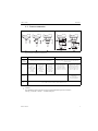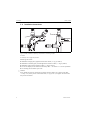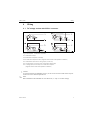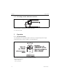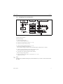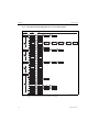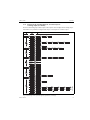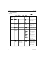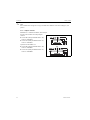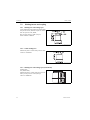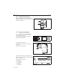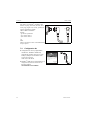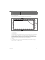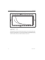
1
Operating manual
Thermophant® T TTR31, TTR35
Temperature switch
BA229R/09/en/07.07
71025405
Release 01.02
Brief overview
Using the following short form instructions you can commission your system easily and swiftly:
Safety instructions
→ Page 4
Æ
Installation
→ Page 6
Æ
Wiring
→ Page 9
Æ
Operation
→ Page 10
Display and operating elements
On-site operation
Operation with PC and configuration software
Æ
Trouble-shooting
→ Page 29
TTR31, TTR35
Table of contents
1
Safety instructions . . . . . . . . . . 4
1. 1
1. 2
1. 3
1. 4
Designated use . . . . . . . . . . . . . . . . . . . . .
Installation, commissioning and operation .
Operational safety . . . . . . . . . . . . . . . . . . .
Return . . . . . . . . . . . . . . . . . . . . . . . . . . . .
2
Device identification. . . . . . . . . 5
4
4
4
4
9. 2 Output . . . . . . . . . . . . . . . . . . . . . . . . . . 32
9. 3 Operating conditions . . . . . . . . . . . . . . . . 32
2. 1 Nameplate . . . . . . . . . . . . . . . . . . . . . . . . . 5
2. 2 Certificates and approvals . . . . . . . . . . . . . 5
3
Installation . . . . . . . . . . . . . . . . 6
3. 1
3. 2
3. 3
3. 4
Incoming acceptance, storage . . . . . . . . . .
Dimensions . . . . . . . . . . . . . . . . . . . . . . . .
Process connection . . . . . . . . . . . . . . . . . .
Installation instructions . . . . . . . . . . . . . . .
4
Wiring. . . . . . . . . . . . . . . . . . . . 9
6
6
7
8
4. 1 DC voltage version with M12x1 connector 9
4. 2 DC voltage version with valve connector . 10
5
Operation . . . . . . . . . . . . . . . . 10
5. 1 On-site operation . . . . . . . . . . . . . . . . . . . 10
5. 2 Operation with PC and Readwin® 2000 . 21
6
Maintenance. . . . . . . . . . . . . . 22
7
Accessories. . . . . . . . . . . . . . . 23
7. 1 Adapter concept for TTR35 . . . . . . . . . . . 23
7.3 Electrical connection . . . . . . . . . . . . . . . . 27
7.4 Configuration kit . . . . . . . . . . . . . . . . . . . 28
8
Trouble-shooting . . . . . . . . . . 29
8. 1
8. 2
8. 3
8. 4
Errors and warnings . . . . . . . . . . . . . . . .
Repair . . . . . . . . . . . . . . . . . . . . . . . . . . .
Disposal . . . . . . . . . . . . . . . . . . . . . . . . .
Software history and
compatibility overview . . . . . . . . . . . . . .
9
29
30
30
31
The most important
technical data . . . . . . . . . . . . . 31
9. 1 Power supply . . . . . . . . . . . . . . . . . . . . . 31
Endress+Hauser
3
Safety instructions
1
TTR31, TTR35
Safety instructions
1. 1 Designated use
The Thermophant® T is a temperature switch for monitoring, displaying and regulating process
temperatures. The device has been safely built with state-of-the-art technology and meets the
applicable requirements and EC Directives. It can, however, be a source of danger if used
incorrectly or for anything other than the designated use.
1. 2 Installation, commissioning and operation
Installation, electrical connection, commissioning, operation and maintenance of the measuring
system must be carried out by trained, qualified specialists authorised to perform such work by
the facility's owner-operator. The specialist must have read and understood these Operating Instructions and must follow the instructions they contain. The device may only be modified and
repair work carried out if this is explicitly permitted in the Operating Instructions. Damaged devices which could be a source of danger may not be commissioned and must be labelled and
identified as defective.
1. 3 Operational safety
The measuring device meets the general safety requirements according to EN 61010-1 and the
EMC requirements according to IEC/EN 61326 in addition to the NAMUR recommendations
NE 21, NE 43 and NE 53.
• Functional safety
The Thermophant® T temperature switches were developed according to the standards IEC
61508 and IEC 61511-1 (FDIS). The device version with PNP switch output and additional
analog output is equipped with fault detection and fault prevention facilities within the
electronics and software.
• Ex-area
The Thermophant® T is not approved for use in Ex-areas.
1. 4 Return
The following procedures must be carried out before a device is returned to Endress+Hauser:
• Always enclose a fully completed “Declaration of Contamination” form with the device. Only
then can Endress+Hauser transport and examine a returned device. A copy of the “Declaration of Contamination” can be found on the second last page of these Operating Instructions.
• Remove all fluid residues. This is particularly important if the fluid is hazardous to health, e.g.
flammable, toxic, caustic, carcinogenic, etc.
#
4
Warning!
Do not return a measuring device if you are not absolutely certain that all traces of hazardous
substances have been removed, e.g. substances which have penetrated crevices or diffused
through plastic.
Endress+Hauser
TTR31, TTR35
2
Device identification
Device identification
2. 1 Nameplate
To identify your device, compare the complete order code and the version information on the
delivery papers with the data on the nameplate.
a0008138
Fig. 1: Nameplate for device identification (as example)
!
m
Order code
r
Connection diagram
n
Serial number
s
Measuring range
o
TAG number
t
Ambient temperature
p
Release number (change status)
u
Degree of protection
q
Connection values
v
Approvals
Note!
The release number indicates the change status of the device. A change in the last two figures
does not have any affect on the compatibility - see also → Chap. 8.
2. 2 Certificates and approvals
CE mark, declaration of conformity
The devices are designed and tested to meet state-of-the-art safety requirements in accordance
with sound engineering practice. They have left the factory in a condition in which they are safe
to operate. The devices comply with the standards EN 61010 -1 "Protection Measures for
Electrical Equipment for Measurement, Control, Regulation and Laboratory Procedures" and
with the EMC requirements of IEC/EN 61326. The device described in these Operating
Instructions is therefore in conformity with the statutory requirements of the EU Directives. The
manufacturer confirms a positive completion of all tests by fitting the unit with a CE mark.
Hygiene standard
The TTR35 temperature switch meets the requirements of Sanitary Standard no. 74-03.
Endress+Hauser confirms this by applying the 3–A symbol (not valid for process connection
conical metal-metal).
Endress+Hauser
5
Installation
TTR31, TTR35
UL listed for Canada and USA
The device was examined by Underwriters Laboratories Inc. (UL) in accordance with the
standards UL 61010B-1 and CSA C22.2 No. 1010.1-92 and listed under the number E225237
UL.
3
Installation
3. 1 Incoming acceptance, storage
• Incoming acceptance:
Check the packaging and the device for damage. Check that the goods delivered are complete
and nothing is missing.
• Storage:
Storage temperature -40 °C to +85 °C (-40 °F to +185 °F).
3. 2 Dimensions
T09-TTR31xxx-06-xx-xx-en-000
Fig. 2: Dimensions in mm (inches)
Version L in 50, 100 and 200 mm (1.97, 3.94 and 7.87"),
for TTR35 as option: L = 23 mm (0.91") and ∅ 4 mm (0.16")
M12x1 connector as per IEC 60947-5-2
M16x1.5 or NPT ½" valve plug as per DIN 43650A/ISO 4400
6
Endress+Hauser
TTR31, TTR35
Installation
3. 3 Process connection
T09-TTR31xxx-17-xx-xx-en-000
Fig. 3: Process connection of the devices
Field of
application
Process
connection
Sensor
length L
Measuring
range
"
TTR31
TTR35
Monitoring, display and control of process temperatures
Monitoring, display and control of process temperatures in
hygienic processes
Item A
Version without
process
connection (’w’).
Suitable welding
bosses and
coupling
(→ Chap. 7)
Item B
Version with
thread process
connection
ANSI NPT ¼"
(m = AF14) and
NPT ½"
(m = AF27)
Item C
Version with
thread process
connection
G¼A (n = AF14)
and G½A
(n = AF27) as
per ISO 228
Item D
Conical metal-metal for
hygienic processes,
G½" thread. Suitable
welding boss available as
accessory (→ Chap. 7.2)
50, 100 and 200 mm (1.97, 3.94 and 7.87")
Item E
Adapter concept - version
with M24x1.5 thread for
adapters with process connection for hygienic processes (→ Chap. 7.1.2)
23 with Ø 4 mm (0.91"
with Ø 0.16")
50, 100 and 200 mm
(1.97, 3.94 and 7.87")
-50 °C to +150 °C (-58 °F to 302 °F)
-50 °C to 200 °C (-59 °F to 392 °F), version TTR35 with neck
Caution!
The maximum process pressure for the conical metal-metal process connection
(see Fig. 3, item D) is 16 bar = 1.6 MPa (232 psi)!
Endress+Hauser
7
Installation
TTR31, TTR35
3. 4 Installation instructions
T09-TTR31xxx-11-00-xx-xx-000
Fig. 4: Possible installation options for temperature monitoring in pipes
m TTR31
n TTR35 for use in hygienic processes
Mounting instructions:
•
•
•
•
•
"
8
Installation at angle pieces, against the direction of flow (→ Fig. 4, Item A).
Installation in smaller pipes, inclined against the direction of flow (→ Fig. 4, Item B).
Installation vertical to the direction of flow (→ Fig. 4, Item C).
The on-site display can be rotated electronically 180° − see section 5. 1 "On-site operation".
The housing can be rotated up to 310°.
Caution!
Do no thread into process connection by turning housing. Always use a wrench (see table,
→ Chap. 3. 3) on the process connnection fluts (→ Fig. 4, Pos. 1) to tighten the sensor into
the process connection.
Endress+Hauser
TTR31, TTR35
Wiring
4
Wiring
4. 1 DC voltage version with M12x1 connector
P01-PTx3xxxx-04-xx-xx-xx-002
Fig. 5: Thermophant® T with M12x1 connector
A1: 1x PNP switch output
A2: 2x PNP switch outputs R1 and m(R2)
A2’: 2x PNP switch outputs R1 and m (diagnosis/break contact with adjustment "DESINA")
A3: 1x PNP switch output and 1x analog output (4 to 20 mA)
A4: 1x analog output (4 to 20 mA) and 1x PNP switch output m(R2)
A4’: 1x analog output (4 to 20 mA) and 1x PNP switch output m
(diagnosis/break contact with adjustment "DESINA")
"
!
Caution!
To avoid the analog input damaging of a PLC, do not connect the active PNP switch output of
the device to the 4...20 mA input of a PLC.
Note!
More informations about DESINA see www.desina.de (→ Chap. 5.1.4 Basic settings).
Endress+Hauser
9
Operation
TTR31, TTR35
4. 2 DC voltage version with valve connector
P01-PTx3xxxx-04-xx-xx-xx-003
Fig. 6: Thermophant® T with M 16x1.5 or NPT ½" valve plug
B: 1x PNP switch output
5
Operation
5. 1 On-site operation
The Thermophant® T is operated by means of three keys. The digital display and the light
emitting diodes (LED) support navigation in the operating menu.
T09-TTR31xxx-19-xx-xx-en-001
Fig. 7: Position of operating elements and possibilities for display
Digital display illumination:
– White = OK status
– Red = error status
10
Endress+Hauser
TTR31, TTR35
Operation
5.1.1 Navigating in the operating menu
T09-TTR31xxx-19-xx-xx-xx-002
Fig. 8: Navigating in the operating menu
A Function group selection
B Function selection
m Enter the operating menu
– Press the E key for longer than 3 s
n Select the "Function group" with the + or − key
o Select the "Function" with the E key
p Enter or change parameters with the + or − key
– Then return to "Function" with the E key
Note: If software locking is enabled, it must be disabled before making entries or changes
q Press the E key several times to return to the "Function group"
– until the appropriate function group is reached again
r Jump back to the measuring position (Home position)
– Press the E key for longer than 3 s
s Query to save data (select "YES" or "NO" with the + or − key)
– Confirm with the E key
!
Note!
Changes to the parameter settings only become effective if you choose s 'YES' when asked to
save data.
Endress+Hauser
11
Operation
TTR31, TTR35
5.1.2 Structure of the operating menu for 1x or 2x switch outputs
T09-TTR31xxx-19-xx-xx-xx-003
Fig. 9: Operating menu: A function groups, B functions, C settings
12
Endress+Hauser
TTR31, TTR35
Operation
5.1.3 Structure of the operating menu for 1x switch output or
1x analog output (4 to 20 mA)
At devices with analog output both output 1 and output 2 can be configured as an analog output.
Furthermore it is possible to configure both output 1 and output 2 as a switch output.
T09-TTR31xxx-19-xx-xx-xx-003
Fig. 10: Operating menu: A function groups, B functions, C settings
Endress+Hauser
13
Operation
TTR31, TTR35
5.1.4 Basic settings
!
Note!
The function group 4-20 is only available if the 4 to 20 mA analog output (0>.,) is selected in
the function group - or . under 6 or 6..
Function
group
Function
Technical unit
Settings
Description
C
Select technical unit:
°C, °F, K
Factory setting: °C
C6
Configure zero
point
,M,
Position adjustment:
within ±10 °C/K
(±18 °F) of the upper
range limit
7@
Accept zero point
,M,
No settings possible (not
available in PC software)
Display
PV: measured value
display
PVRO: measured value
display rotated 180°
SP: set switch point
display
SPRO: set switch point
display rotated 180°
OFF: display off
66
14
Damping:
display value,
output signal
66
OFFR: display off rotated
180°
Factory setting:
measured value (PV)
,M,
Measured value damping
with regard to display
value and output: 0 (no
damping) or 9 to 40 s (in
increments of 1 second)
Factory setting: 0 s
Endress+Hauser
TTR31, TTR35
Operation
Function
group
Function
DESINA
Settings
Description
PIN assignment of the
M12 connector is in
accordance with the
guidelines of DESINA
Factory setting: NO
!
Note!
Configuration DESINA is
only possible, if output 1
and output 2 are
selected.
5.1.5 Settings for output - 2x switch output
• Hysteresis function
The hysteresis function enables two-point control via a hysteresis. Depending on the
temperature T, the hysteresis can be set via the switch point SP and the switch-back point
RSP.
• Window function
The window function enables the monitoring of a process temperature range.
• NO contact or NC contact
This switch function is freely selectable.
• Factory setting (if no customer-specific settings have been ordered):
Switch point SP 1: 45 °C (113.0 °F); Switch-back point RSP 1: 44.5 °C (112.1 °F)
Switch point SP 2: 55 °C (131.0 °F); Switch-back point RSP 2: 54.5 °C (130.1 °F)
• Range of adjustment
LRL = Lower Range Limit
URL = Upper Range Limit
LRV = Lower Range Value
URV = Upper Range Value
Endress+Hauser
15
Operation
TTR31, TTR35
T09-TTR31xxx-05-xx-xx-xx-001
Fig. 11: Switch point functions
a: Hysteresis-function
b: Window-function
m Window - NC contact
n Hysteresis - NC contact
o Window - NO contact
p Hysteresis - NO contact
SP switch point; RSP switch-back point
Function
group
Function
6
6.
Output 1
Switching
characteristic
Settings
Description
WINC:
window/NC contact
HYNC:
hysteresis/NC contact
WINO:
window/NO contact
HYNO:
hysteresis/NO contact
Factory setting: HYNO
.
Output 2,
as option
.
16
Switch point value
,M,
Switch point
-49.5 to 150 °C
(-57.1 to 302 °F)
in increments of 0.1 °C
(0.18 °F)
Endress+Hauser
TTR31, TTR35
Operation
Function
group
Function
.
Output 1
Settings
Description
Switch-back point
value
,M,
Switch-back point
-50 to 149 °C
(-58 to 300 °F)
in increments of 0.1 °C
(0.18 °F)
.
Switch point delay
,M,
Delay time
0...99 s
in increments of 0.1 s
Factory setting: 0 s
.
Switch-back point
delay
,M,
Delay time 0...99 s
in increments of 0.1 s
Factory setting: 0 s
.
Output 2,
as option
Min. distance between SP and RSP: 0.5 °C/K (0.9 °F)
5.1.6 Settings for output - 1x switch output and 1x analog output (4 to 20 mA)
Function
group
Function
6
6.
Output 1
Switching
characteristic
Settings
Description
WINC:
window/NC contact
HYNC:
hysteresis/NC contact
WINO:
window/NO contact
HYNO:
hysteresis/NO contact
.
Output 2,
as option
0>.,
4 - 20: analog output
Factory setting: HYNO
.
Endress+Hauser
Switch point value
,M,
Switch point
-49.5 to 150 °C
(-57.1 to 302 °F)
in increments of 0.1 °C
(0.18 °F)
17
Operation
TTR31, TTR35
Function
group
Function
.
Output 1
Settings
Description
Switch-back point
value
,M,
Switch-back point
-50 to 149 °C
(-58 to 300 °F)
in increments of 0.1 °C
(0.18 °F)
.
Switch point delay
,M,
Delay time
0...99 s
in increments of 0.1 s
Factory setting: 0 s
.
Switch-back point
delay
,M,
Delay time 0...99 s
in increments of 0.1 s
Factory setting: 0 s
.
Output 2,
as option
Min. distance between SP and RSP: 0.5 °C/K (0.9 °F)
0>.,
Value for 4 mA
(LRV)
,M,
-50 to 130 °C
(-58 to 266 °F)
Lower range value in
increments of 0.1 °C
(0.18 °F)
Factory setting:
0.0 °C (32.0 °F)
Value for 20 mA
(URV)
,M,
-30 to 150 °C
(-22 to 302 °F)
Enter upper range value
in increments of 0.1 °C
(0.18 °F)
Factory setting:
150 °C (302 °F)
7@
Temperature
applied for 4 mA
(LRV)
,M,
Take temperature value
as lower range value
(not via PC software)
7@
Temperature
applied for 20 mA
(URV)
,M,
Take temperature value
as upper range value
(not vial PC software)
Analog
output
18
Endress+Hauser
TTR31, TTR35
Operation
Function
group
Function
0>.,
6
Error current
Analog
output
Settings
Description
Current value in event
of error:
MIN = ≤ 3.6 mA
MAX = ≥ 21.0 mA
HOLD = last value
Factory setting:
MAX
Min. distance between SETL and SETU: 20 °C/K (36 °F)
!
Note!
The function group 4-20 is only available if the 4 to 20 mA analog output (0>.,) is selected in
the function group - or . under 6 or 6..
5.1.7 Settings for service functions
Function
group
Function
Settings
Description
Locking code
,
Enter the locking code
for enabling the device.
Change locking
code
,
Freely selectable code
1...9999.
0 = no locking;
A locking code already
assigned can only be
changed by first entering
the old code for enabling
the device.
Reset
Reset all entries to the
factory setting
@
Revision counter
,
Increases by 1 with each
configuration
@
Last device status
,
Displays the last device
status to occur ≠ 0
Service
functions
Endress+Hauser
19
Operation
TTR31, TTR35
Function
group
Function
.
Service
functions
Simulation
output 1 or 2
Settings
Description
66
OFF:
No simulation
OPEN:
Switch output open
CLOS:
Switch output closed
3.5:
Simulation values for
analog output in mA
(3.5/4.0/8.0/12.0/
16.0/20.0/21.7)
(if output 2
available)
/M1
(if analog
output
available)
20
@
Max. indicator
,M,
Display of max.
measured
process value
@
Min. indicator
,M,
Display of min.
measured
process value
Endress+Hauser
TTR31, TTR35
Operation
5. 2 Operation with PC
The device can be configured with the configuration software ReadWin® 2000 or FieldCare. For
the connection between the USB port of the computer and the device a configuration kit (e.g.
TXU10) is necessary.
T09-TTR31xxx-04-xx-xx-en-004
Fig. 12: Operation with PC
Item 1: PC with configuration software ReadWin® 2000 or FieldCare
Item 2: Configuration kit TXU10-AA or FXA291
Item 3: Temperature switch
5.2.1 Additional operating options
In addition to the operating options listed in the previous "On-site operation" section, the
ReadWin® 2000 or FieldCare configuration software provides further information on the
Thermophant® T:
Function group
Description
SERV
Number of switch changes for output 1
Number of switch changes for output 2
Device status
INFO
Tag number
Order code
Limit switch serial number
Sensor serial number
Electronics serial number
Endress+Hauser
21
Maintenance
TTR31, TTR35
Function group
Description
INFO
Device release
(change status)
Hardware version
Software version
5.2.2 Hints for the configuration with Readwin® 2000
Comprehensive information on the ReadWin ® 2000 configuration software may be found in
the Operating Instructions BA137R/09/en.
5.2.3 Hints for the configuration with FieldCare
FieldCare is an universal configuration software based on FDT/DTM technology.
!
Note!
• To configure the Thermophant® T TTR31/35 with FieldCare the “PCP (ReadWin)
Communication DTM” and the Thermophant Device-DTM are required.
• All devices with software version 1.01.00 or higher can be configured with FieldCare.
• The device supports only offline configuration and up-/download of parameters. The online
configuration is not supported.
Detailed information concerning FieldCare may be found in the operation manual (BA027S/c4)
or see: www.endress.com.
6
"
22
Maintenance
Any buildup on the sensor can have a negative effect on the sensor response time. For this reason, check the sensor for buildup at regular intervals.
Caution!
Make sure the process is unpressurized before you remove the device! Do not twist the device
out of the process connection thread at the housing. Always use a suitable open-ended wrench
for disassembly work (→ Chap. 3. 3 and → Fig. 4).
Endress+Hauser
TTR31, TTR35
7
Accessories
Accessories
If ordering accessories, please specify the serial number of the unit! All dimensions in the
drawings are given in mm (inches).
7. 1 Adapter concept for TTR35
The process connection is an adapter and the sensor module has an adapter thread
(see section 3. 3, process connection). As a result, the process connection can easily be changed
at a later stage.
7.1.1 Adapter change
The adapter can be changed on TTR35.
T09-TTR31xxx-17-xx-xx-xx-000
Fig. 13: Changing the adapter
m Sensor module with adapter thread
n Standard O-ring
o Adapter
Please note the following when changing the adapter:
• Use a new O-ring. Diameter 15.54 x 2.62 mm (0.612" x 0.103").
EPDM 70 Shore FDA 3-A approved.
• Fix the device (sensor module) in place with an open-ended wrench AF 27. Never hold the
housing of the device to loosen or tighten the process connection adapter.
• The adapter can be screwed on with an open-ended wrench AF 27 or AF 32, depending on
the process connection, (see section 7.1.2 adapter versions).
The maximum torque is 80 Nm. The thread can become loose if exposed to severe strain
through pressure and temperature. For this reason, the air-tightness must be checked
regularly and the thread tightened if necessary.
• When changing the adapter, make sure that the sensor tube of the sensor is not damaged.
Endress+Hauser
23
Accessories
!
TTR31, TTR35
Note!
We recommend to change the O-ring in the same time frame as of all other sealings in your
process.
7.1.2 Adapter versions
EN10204-3.1 = Material certificate (melt analysis)
DTT35: order numbers for clamp adapter
versions.
• Version DB (Clamp ISO2582 DN25 - 38):
order no. 52023994
• Version DL (Clamp ISO2582 DN40 - 51):
order no. 52023995
Optional with EN10204-3.1:
• Version DB (Clamp ISO2582 DN25 - 38):
order no. 52024001
• Version DL (Clamp ISO2582 DN40 - 51):
order no. 52024002
P01-PTx3xxxx-06-xx-xx-en-009
24
Endress+Hauser
TTR31, TTR35
Accessories
TTR35: order numbers hygiene adapter
versions.
• Version LB
(Varivent F pipe DN25 - 32, PN40):
Order no. 52023996
• Version LL
(Varivent N pipe DN40 - 162, PN40):
Order no. 52023997
• Version HL (APV-Inline DN50 PN40):
Order no. 52024000
• Version PH (DIN11851 DN40 PN40):
Order no. 52023999
• Version PL (DIN11851 DN40 PN40):
Order no. 52023998
Optional with EN10204-3.1:
• Version LB
(Varivent F pipe DN25 - 32, PN40):
Order no. 52024003
• Version LL
(Varivent N pipe DN40 - 162, PN40):
Order no. 52024004
• Version HL (APV-Inline DN50 PN40):
Order no. 52024007
• Version PH (DIN11851 DN40 PN40):
Order no. 52024006
• Version PL (DIN11851 DN40 PN40):
Order no. 52024005
P01-PTx3xxxx-06-xx-xx-en-010
7.1.3 O-ring for adapter replacement
O-ring 15.54 x 2.62 mm (0.61 x 0.1 in), EPDM 70 Shore FDA, order no. 51008363
Endress+Hauser
25
Accessories
7.2
TTR31, TTR35
Welding bosses and coupling
7.2.1 Welding boss with sealing taper
Collar welding boss moveable with sealing taper
and pressure screw; material of parts in contact
with the process: 316L, PEEK,
max. process pressure 10 bar (145 psi)
Order number: 51004751
T09-TSM470AX-06-09-00-en-000
7.2.2 Collar welding boss
Material of parts in contact with process: 316L
Order no. 51004752
T09-TSM470BX-06-09-00-en-000
7.2.3 Welding boss with sealing taper (metal-metal)
Welding boss
Seal, metal-metal,
Material of parts in contact with process: 316L
Max. process pressure 16 bar (232 psi)
Order no. 60021387
a0006621
26
Endress+Hauser
TTR31, TTR35
Accessories
7.2.4 Coupling with sealing taper
Moveable coupling, G½" process connection,
coupling and parts in contact with process: 316L
Order no. 51004753
T09-TSM470AX-06-09-00-en-001
7.3
Electrical connection
7.3.1 Plug-in jack; connecting cable
Coupling M12x1; straight
Connection to M12x1 housing connector
Order number: 52006263
P01-PMP13xxx-00-xx-00-xx-003
Coupling M12x1; elbowed
Connection to M12x1 housing connector
IP 67, PG7
Order number: 51006327
T09-TTR3xxxx-06-09-xx-en-000
PVC cable, 4 x 0.34 mm2 (22 AWG) with
M12x1 coupling, elbowed, screw plug, length
5 m (16.4 ft), IP 67
Order number: 51005148
Core colours:
- 1 = BN brown
- 2 = WH white
- 3 = BU blue
- 4 = BK black
Endress+Hauser
T09-TTR31xXX-00-00-xx-xx-002
27
Accessories
TTR31, TTR35
PVC cable, 4 x 0.34 mm2 (22 AWG) with
M12x1 coupling, with LED, elbowed, 316L
screw plug, length 5 m (16.4 ft), specially for
hygiene applications, IP 69K
Order number: 52018763
Display:
−gn: device operational
−ye1: switch status 1
−ye2: switch status 2
ye 1
ye 2
gn
!
Note!
Not for use at devices with "4 to 20 mA analog
output" option!
7.4
T09-TTR31xxx-00-00-xx-xx-001
Configuration kit
• Configuration kit for PC-programmable
transmitters - ReadWin® 2000 setup
program and interface cable for PCs with
USB port; Adapter for transmitters with
4-pole post connector
Order code: TXU10-AA
• ReadWin® 2000 can be downloaded free of
charge directly from the internet at the
following address:
www.endress.com/readwin
28
a0008067
Endress+Hauser
TTR31, TTR35
8
Trouble-shooting
Trouble-shooting
8. 1 Errors and warnings
If an error in the device occurs, the colour of the status LED changes from green to red and the
digital display illumination changes from white to red. A status LED flashing red and green
signals a warning. The display shows:
• E-code for errors
In the event of an error message, the measured value is uncertain.
• W-code for warnings
In the event of a warning, the measured value is reliable.
Code
Explanation
Remedy
E011
Device configuration faulty
Reset device (→ Chap. 5.1.7)
E012
Error in measurement or medium
temperature outside specification
Check medium temperature, return
device to E+H where necessary
E019
Power supply outside specification
Check operating voltage
Memory error
Return device to E+H
E022
Power is only supplied to the device via
the communication interface
(measurement is deactivated)
Check operating voltage
E025
Switching contact 1 is not open although
it should be
Switching contact defective,
return device to E+H
E026
Switching contact 2 is not open although
it should be
Switching contact defective,
return device to E+H
E040
VCC (Controller voltage) is out of
working area
Return device to E+H
E042
Output current can no longer be
generated (only for 4 to 20 mA output,
e.g. load at analog output too high or
open analog output)
Check load.
Switch off analog output via
configuration, if it isn’t required,
→ Chap. 5.1.6.
E015
E020
E021
Endress+Hauser
29
Trouble-shooting
TTR31, TTR35
Code
Explanation
Remedy
E044
Output current drifts too much
(± 0.5 mA)
Return device to E+H
Code
Explanation
Remedy
W107
Simulation active
Switch off the output simulation for
output 1 and output 2
W202
Measured value outside of the sensor
range
Operate the device in the specified
temperature range
W209
Device starts
W210
Configuration modified (warning code
will be displayed for 15 s approx.)
W212
Sensor signal outside the permitted range
Operate the device in the specified
temperature range
W250
Number of switch cycles exceeded
Replace the device
W270
Short-circuit or overload at output 1
Check output wiring.
Extend the load resistance at output 1
W280
Short-circuit or overload at output 2
Check output wiring.
Extend the load resistance at output 2
8. 2 Repair
A repair is not planned.
8. 3 Disposal
Please pay particular attention to the local disposal regulations of your country. When disposing,
ensure that the materials of the device components are separated and processed accordingly.
30
Endress+Hauser
TTR31, TTR35
The most important technical data
8. 4 Software history and compatibility overview
The release number on the nameplate and in the Operating Instructions indicates the change
status of the device: XX.YY.ZZ (example 01.02.01).
XX
Change in the main version.
Compatibility no longer provided. Device and Operating Instructions change.
Change in functionality and operation.
Compatibility provided. Operating Instructions change.
Trouble-shooting and internal modifications.
Operating Instructions do not change.
YY
ZZ
Software history
Date
Release no.
device
06.2004
01.00.00
12.2004
01.01.00
New analog electronics
BA201r/09/en/02.05
(51009833)
02.2005
01.02.00
Internal
BA201r/09/en/02.05
(51009833)
02.2006
01.02.01
Parameter functional safety for the optional
analog output is not applicable
BA229r/09/en/03.06
(71025405)
9
Changes in software
Documentation
KA174r/09/en
(51008032)
The most important technical data
9. 1 Power supply
Supply voltage
• DC voltage version 12...30 V DC
Current consumption
• Without load < 60 mA, with reverse polarity protection
Power supply failure
• Behaviour in case of overvoltage (> 30 V)
The device works continuously up to 34 V DC without any damage. No damage is caused to
the device in case of a short-term overvoltage up to 1 kV (as per IEC 61000-4-5). If the supply
voltage is exceeded, the properties specified are no longer guaranteed.
• Behaviour in case of undervoltage
If the supply voltage drops below the minimum value, the device switches off (status as if not
supplied with power = switch open).
Endress+Hauser
31
The most important technical data
TTR31, TTR35
9. 2 Output
Switching capacity
• Switch status ON: Ia ≤ 250 mA
• Switch status OFF: Ia ≤ 1 mA
• Switching cycles: > 10,000,000
• Voltage drop PNP: ≤ 2 V
• Overload protection
Automatic load testing of switching current; output is switched off in case of overcurrent, the
switching current is tested again every 0.5 s; max. capacitance load: 14 μF for max. supply
voltage (without resistive load).
Load (analog output)
• Max. (Vsupply - 6.5 V) / 0.022 A
Signal on alarm
• Analog output: ≤ 3.6 mA or ≥ 21.0 mA adjustable
(if setting ≥ 21.0 mA the output is ≥ 21.5 mA)
• Switch outputs: in safe state (switch normally open)
9. 3 Operating conditions
• Any orientation
• Any position-dependent zero shift can be corrected
Offset: ±20 % URL
9.3.1 Environment
• Ambient temperature range
–40...+85 °C (-40...+ 185 °F)
• Storage temperature
–40...+85 °C (-40...+ 185 °F)
9.3.2 Process
Process temperature limits
• -50 to 150 °C (-58 to 302 °F) generally,
• -50 to 200 °C (-58 to 392 °F) version TTR35 with neck
"
Caution!
Restrictions depending on process connection and ambient temperature:
• No restriction with coupling (see Accessories, → Chap. 7.2.1, → Chap. 7.2.4, order no.
51004751, 51004753) and neck tube length min. 20 mm (0.79").
• with process connection:
32
max. ambient temperature
max. process temperature
up to 25 °C (77 °F)
no restriction
up to 40 °C (104 °F)
135 °C (275 °F)
Endress+Hauser
TTR31, TTR35
The most important technical data
up to 60 °C (140 °F)
120 °C (248 °F)
up to 85 °C (185 °F)
100 °C (212 °F)
Process pressure limits
Maximum permitted process pressure depending on the insertion length.
a0008063-en
Fig. 14: Maximum permitted process pressure
L = insertion length
p = process pressure
The diagram takes into consideration not only the overpressure but also the pressure load caused
by the flow, whereby a safety factor of 1.9 has been specified for operation with flow. The
maximum permitted static operating pressure is lower at greater insertion lengths due to the
increased bending load caused by the flow. The calculation assumes the maximum permitted
medium velocity for the respective insertion length (see diagram below).
"
Caution!
The maximum process pressure for the conical metal-metal process connection (see Fig. 3,
item D) is 16 bar = 1.6 MPa (232 psi)!
Endress+Hauser
33
The most important technical data
TTR31, TTR35
Permitted flow velocity depending on the insertion length.
a0008065-en
Fig. 15: Permitted flow velocity
L = insertion length, during flow
v = flow velocity
Medium: ----- air; - - - - - water
The permitted flow velocity is the minimum from resonance velocity (resonance distance 80%)
and load or buckling caused by flow, which would lead to failure of the thermometer tube or to
exceedance of the safety factor (1.9). Calculation was performed for the specified limit operating
conditions of 200°C (392°F) and ≤10 MPa (1450 PSI) process pressure.
34
Endress+Hauser
www.endress.com/worldwide
BA229R/09/en/07.07
71025405
CCS/FM6.0+SGML