1
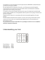
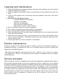
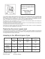
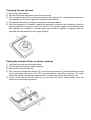
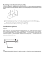
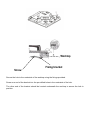
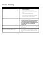
Gas Hobs User and Installation Manual Model: UGH602SS Your 1 Year Guarantee Your appliance carries a 1 year parts and labour warranty. To fulfill the conditions of your guarantee, the appliance must be correctly installed, operated in accordance with the instructions and only be used for normal domestic purposes. Please note that the guarantee and service availability only apply to the United Kingdom mainland. Customer Service In case of difficulty please call the Customer Service Helpline number. 0844 800 7848 • When calling customer service, please ensure you have the model and serial number to hand. • Please keep your receipt or invoice in a safe place as they will be required as proof of date of purchase. Appliance 365 Limited, 730 Mandarin Court, Centre Park, Warrington, WA1 1GG These instructions have been drawn up for your safety and that of others. We therefore request you read them carefully before installing and using this appliance. Keep this instruction manual in a convenient place near the appliance for future reference. If the appliance is sold or moved, make sure that the manual is handed over to the new user. Installation Installation of this appliance and its connection to the electric and gas supply must only be carried out by QUALIFIED PERSONNEL. In the case of gas connection this hob must be installed by a Gas Safe Registered Installer. Before undertaking any maintenance or repair procedure, it is important to check that the appliance is DISCONNECTED from the electrical supply. DO NOT attempt to modify or change the characteristics of this product. 1. After removing the appliance from the packaging, make sure that it is not damaged and that the electrical lead is in perfect condition. Report any damage or losses to your dealer before installing or putting the appliance into operation. 2. Check the Data Plate against the domestic supply to ensure that the appliance is correctly calibrated for the type of gas and electricity supply in the property. 3. If this appliance is not equipped with Flame Supervisory Devices on each gas burner, then from 1st January 2008 it is illegal to install the appliance in a property classified as a ‘Multi-Dwelling’; typically flats and apartments. 4. The Manufacturer declines all responsibility for failure to comply with Health and Safety accident prevention regulations. 5. Gas cooking appliances produce heat and moisture in the room in which they are installed. Make sure there is sufficient ventilation in the room where this appliance is to be installed. An opening window or external door is required, and where ventilation grilles are installed, these should be free from obstruction and in good working order. Alternatively ventilation can be via means of an extractor hood with discharge pipe to the outside. Poor ventilation produces a shortage of oxygen. 6. If the appliance is used intensively for a long period of time the effectiveness of the ventilation may have to be increased, for example by opening a window or external door or by increasing the power selection of any electric extractor fan. During use This product is designed for domestic use only, for the cooking of food, and not for professional catering purposes. It should not be used for any other purpose. After using the appliance, make sure that all controls are “OFF” or in the “CLOSED” position. If you use an electrical socket close to this appliance, take care that the cable to the appliance you are using cannot make contact with the hot parts of this appliance. Do not use unstable pans and always ensure the pan handle is positioned away from the edge of the hob. Do not cover the hob or place combustible materials on or near the surface when the hob is in use Do not fill deep fat frying pans more than one third full of oil and NEVER leave them unattended. In the event of a fire: 1. Don’t take any risks. 2. Turn off the heat only if it is safe to do so. 3. Never throw water over it. 4. Don’t tackle the fire yourself. 5. GET OUT, STAY OUT and CALL 999. General safety This appliance must only be used by adults. Make sure that children are kept away from hot cooking areas when the appliance is in use. Children must not be left un-supervised or allowed to touch or play with the appliance controls. This appliance is not intended for use by persons (including children) with reduced physical, sensory and mental capabilities, or lack of experience and knowledge, unless they have been given supervision or instruction concerning use of the appliance by a person responsible for their safety. The exposed parts of this appliance heat up during cooking and remain hot for some time, even after it is switched off. Keep children well away at all times. Please remove all packaging prior to use and dispose of or recycle accordingly. Packaging materials (e.g.; polystyrene and plastic items) must be kept out of reach of babies and young children at all times due to risk of suffocation. Environmental protection advice All the materials used in the construction of this appliance are environmentally friendly and recyclable. Please make your contribution to conserving the environment by using the local waste collection channels available in your area. Disposal of your old appliance Before discarding of your old appliance: • Switch off and disconnect it from the power supply • Cut off the plug • Cut off the cable directly behind the appliance to prevent mis-use. These steps should be carried out by a suitably qualified and competent person. This appliance is marked according to the European directive 2002/96/EC on Waste Electrical and Electronic Equipment (WEEE). By ensuring this product is disposed of correctly, you will help prevent potential negative consequences for the environment and human health, which could otherwise be caused by inappropriate waste handling of this product. The symbol on the product indicates that this product may not be treated as household waste. Instead it shall be handed over to the applicable collection point for the recycling of electrical and electronic equipment. Disposal must be carried out in accordance with local environmental regulations for waste disposal. For more detailed information about treatment, recovery and recycling of this product, please contact your local council, your household waste disposal service or the shop where you purchased the product. The manufacturer cannot be held liable for any damage caused due to non-compliance with these important safeguards. Understanding your hob Front left burner Rear left burner Rear right burner Front right burner 3000w 1850w 1850w 1000W Instructions for use The symbols on the hob control knobs are as follows: ● No gas flow or OFF Maximum gas flow Minimum gas flow All operating positions must be set between the maximum and minimum flow settings, and never between the maximum setting and the closed position. Igniting the burners To obtain a flame more easily, light the burner before placing a cooking utensil on the pan stand To light a burner, depress the control knob fully and turn it anticlockwise to the “maximum flow” setting. Press the ignite button once. Once the burner is lit, allow the control knob to spring back into the upright position before adjusting the flow. In the event of a power cut, the burners can be ignited by a lit match or taper; proceed as described above. If the flame does not light after a few attempts, check that the “burner cap” and “flame ring” are correctly positioned. To extinguish the flame and turn off the burner, turn the control knob clockwise to the ● s ymbol. Before removing pans from the burners, always lower or turn off the flame. Do not leave any empty pots or pans on a lit burner. Optimum use of the hob For lower gas consumption and better efficiency, use only flat-bottomed pans of dimensions suitable for the burners, as shown in the table below. Always ensure that the pans are centred on the pan supports to ensure they remain stable thus avoiding the risk of spillages. Please note, as soon as a liquid comes to the boil take care to turn the flame down to a level that will just keep it boiling or simmering. Burner Minimum Diameter Large (rapid) 200mm Medium (semi-rapid) 160mm Small (auxiliary) 100mm Maximum Diameter 220mm 180mm 140mm Caution: Hot fat is highly flammable so pay extra attention when preparing food with grease or oil. Frying should only be carried out under constant supervision. Cleaning and maintenance Before undertaking any cleaning operation, disconnect the appliance from the electrical supply and allow it to cool down. Keep the appliance thoroughly cleaned. Accumulations of food residues may cause fire risks. Clean the hob regularly with a soft damp cloth and lukewarm water with a little liquid detergent. Do not use the following products: - household detergents or bleaches. - soaped scouring pads. - steel wool scouring pads. - stain removers for baths or sinks. - paint remover, acids or similar solvents. Do not use Steam Cleaners to clean this appliance. Do not leave components immersed in water for long periods. Do not use scourers or abrasive materials that may scratch. Wash enamelled parts with lukewarm water and detergent: Do not use abrasive products which may cause damage. Wash the burner caps and burner rings frequently with hot water and detergent, taking care to remove all deposits. Thoroughly rinse and dry each component and ensure the burner holes are clear. The hob pan stands can also be washed in a dishwasher. Routine maintenance Check the condition of the flexible gas pipe for cracking, and the L.P.G. pressure regulator (if installed) periodically. If anomalies are found, do not attempt repairs but have the faulty part replaced by a Qualified Engineer. Should the appliance gas taps become stiff or difficult to turn, contact our service department. Under no circumstances should repairs be attempted by Non Qualified Personnel. Service and parts Before leaving the factory, this appliance was tested and adjusted by specialist skilled staff to give the best operating results. In the event of component failure or malfunction, do not attempt to repair the appliance yourself. Repairs by unskilled persons may cause damage and accidents. First refer to the Troubleshooting guide at the back of this manual. If you do not find the necessary information, contact your nearest Service Centre, specifying the nature of the problem, the model number of the appliance and the serial number. This information is provided on the data label which is located on the underside of the hob. Always make a note of the model and serial number before the appliance is installed as this will be required in the event of any servicing requirement. Model Number: Serial Number: Any service work on this appliance should only be carried out by an Authorised Technical Service Centre, who will always use original spare parts. Instructions for installation CAUTION: This appliance must only be installed and used in rooms with a means of permanent ventilation, compliant to current Gas Regulations. Installation of the appliance and its connection to the gas and electrical supply must only be carried out by QUALIFIED PERSONNEL. Before any maintenance or repairs are carried out, it is important to check that the appliance is DISCONNECTED from the electrical supply. The Manufacturer declines all responsibility for any damage arising from installation in breach of the regulations in force or from failure to comply with Health & Safety Regulations. Requirements for installation For the proper operation of a gas appliance, the air necessary for the combustion of the gas must be able to flow into the room naturally. The air must flow into the room directly through openings in the outside walls. These openings must have an unobstructed cross-section not less than 2m3/h for each kw of power (see total power in kw on the appliance data plate). This opening must be constructed so that it will not be obstructed from the inside or out, or located close to the floor. The opening is recommended to be on the side opposite to that on which the flue gases are discharged. If it is not feasible to provide these openings in the room where the appliance is installed, the necessary air may be taken from an adjacent room, provided that: • this room is not a bedroom or a hazardous environment; • this room has ventilation; • the ventilation between the room where the appliance is installed and the adjacent room has opening window/s and/or an external door. L.P.G models must not be installed in a room or internal space below ground level, e.g. in a basement Discharge of flue gases All gas cooking appliances give off cooking vapours and combustion gases; it is therefore advisable to have an extractor hood fitted above the cooker to discharge cooking vapours and flue gases externally. Where this is not possible, an opened door and or window, or electrically operated wall or window extractor is recommended throughout the cooking process. Connection to the gas supply The gas connection must be made in accordance with Gas Regulations. When installing, fit an isolation tap upstream of the hob. The appliance leaves the factory tested and set for the type of gas indicated on the data plate on the underside of the appliance. Make sure that the type of gas to be supplied to the appliance is the same as that shown on the plate. Otherwise, follow the instructions provided in the “Adapting to different types of gas” section. For maximum efficiency and minimum consumption, make sure that the gas supply pressure complies with the values shown. If the gas used is different from that specified (or variable) a suitable pressure regulator must be installed on the supply pipeline. The male gas inlet union (C) must be fitted on the end of the gas rail, with gas seal (B) between the union and nut (where applicable) (A) that is attached to the appliance as shown in the illustration. Screw the parts together without forcing them. Fit the union so that it points in the required direction then tighten all the parts. When making the connection, take care not to apply stresses of any kind to the appliance. Connection Make the connection to the gas system using a rigid metal pipe, or with a stainless steel flexible hose / catering hose complying with Gas Safe Regulations. If flexible hoses are used, take care that they do not come into contact with the heated surfaces of the underside of the hob or the casing of an oven built-in below. When the installation is complete, always check all the unions are absolutely gas tight using a manometer or Approved Leak Detection Fluid – Do Not use a soapy water solution and NEVER use a naked flame to check for leaks. Electrical connection The appliance is manufactured to operate with a power supply voltage of 230V to 240V single-phase. The connection must be made in accordance with I.E.E. Regulations and Laws in force. Before making the connection, make sure that: 1) The safety circuit-breaker and the electrical system are able to withstand the load of the appliance (see data plate). 2) The power supply system has an Earth connection in good working order in accordance with the Regulations in force; 3) The socket or omni polar isolation switch used is easily accessible with the appliance installed. The wires in the mains cable are coloured in accordance with the following code: Green & Yellow = Earth, Blue = Neutral, Brown = Live If you wish to make a direct connection to the mains, an omni polar switch with a separation gap between the contacts of at least 3 mm, with suitable R.C.D. / R.C.C.B., current rating for the load and complying with the regulations in force, must be installed between the appliance and the mains. The switch must not break a contact in the yellow/green Earth wire. The Brown live wire (connected to the “L” terminal of the terminal board) must always be connected to the live wire of the power supply. The Blue neutral wire (connected to the “N” terminal of the terminal board) must always be connected to the neutral wire of the power supply. In all cases, the power supply lead must be positioned so that it does not reach a temperature 50oC above the room temperature at any point. Replacing the power supply lead If the lead has to be replaced, only HO5RR-F or HO5RN-F type cables suitable for the load and the operating temperature must be used. In addition, the yellow/green earth wire must be about 2 cm longer than the live and neutral wires. Adapting to the different types of gas MAX OUTPUT MIN OUTPUT G20 20mbar G30 28-30mbar Kw Kw Jet Size mm Jet Size mm Small Auxiliary 1.00 0.60 Medium Semi-Rapid 1.85 0.90 Large Rapid 3.0 1.2 BURNER TYPE Gas intake connection Electricity supply G.1/2″ 220-240v~50/60Hz 0.72 0.97 1.15 0.49 0.67 0.87 Changing the gas injectors 1) Remove the pan stands. 2) Remove the burner and flame caps from the burners. 3) Use a socket wrench (B) to unscrew and remove the injectors (A), replacing them with those corresponding to the type of gas to be used (see table above). 4) Reassemble the parts, reversing the operations described above. 5) Once this operation is complete, replace the data plate located on the underside of the hob with one relevant to the type of gas in use. If the L.P.G. pressure of gas used is different from that specified (or variable), a suitable piped gas pressure regulator complying with the standard must be installed on the supply pipeline. Setting the minimum flame or simmer settings 1) 2) 3) 4) Light the burner as previously described. Turn the tap to the minimum flame position. Remove the control knobs (M). Use a long thin straight screwdriver (D) to turn the by-pass screw (C) located down the centre of the tap spindle (as shown). For LPG, turn the by-pass screw fully clockwise. The result should be a small, homogeneous flame which is uniform around the entire burner ring. 5) Finally, check that the burner does not go out when the tap is turned quickly from the maximum to the minimum position. Building into fitted kitchen units This hob is designed for installation into fitted kitchen units up to 600mm deep on the assumption that the clearances indicated below are observed. The worktop height should be between 40 and 50mm. A. The height clearance to the underside of a chimney hood not less than 750mm (a). B. Any combustible surface taller than the height of the hob itself must be at least 150mm away from the opening into which the hob is inserted (b). C. The clearance from the wall, minimum gap of 65mm (C). Installation options Option1: When fitting a gas hob above a drawer or standard housing unit, suitable precautions must be taken to prevent contact with the casing of the hob, which becomes very hot during operation. The recommended method for overcoming this problem is to fix a wooden panel within the cabinet at a distance of 15mm below the underside of the hob (see fig 1). This panel must have adequate ventilation to the rear. Ventilation slot Fig 1 The panel underneath the hob must be easily removable to allow for any servicing requirements. Option 2: If installing this appliance above an oven it is necessary to remove the front cross rail of the oven housing unit to provide adequate ventilation within the cabinetry. Installation dimensions B A A = W557mm B = D477mm Inserting and fixing the hob Before inserting the hob into the work surface, place the adhesive seal (a) around the underside edge of the hob. It is important to fix this gasket evenly, without gaps or overlapping to prevent liquids from seeping underneath the hob. 1) Remove the pan stands and the burner caps then turn the hob upside down, taking care not to damage the ignition plugs and the thermocouples. 2) Place the gasket around the bottom edge of the hob as shown in the illustration overleaf (left). 3) Place the hob in the installation opening and push it down so that the hob is resting firmly on the cabinet. 4) Secure the hob in position using the fixing brackets supplied. Worktop Fixing bracket Screw Secure the hob to the underside of the worktop using the fixings provided. Screw one end of the bracket into the pre-drilled holes in the underside of the hob. The other end of the bracket should be located underneath the worktop to secure the hob in position. Trouble Shooting Symptom Solution There burner fails to ignite • Check that the unit is wired in and the power supply is switched on • • Check the main fuse has not blown Check there is not a problem with your gas supply • • Check the plate is clean and dry Check the burner cap and crown have been replaced correctly e.g. after cleaning • Check the main jet is not blocked and the burner crown is clear of food particles • Check that the burner is dry and that food spillage or cleaning fluids are not present on the burner. This can be dried with a cloth and stubborn marks cleaned away with a dry nylon brush (old toothbrush etc) The burner sounds noisy • It is natural for the burner to emit noise as the gas is being drawn through the burner and may reduce as they heat up The burner is emitting a popping sound • This is a natural occurrence when the burner is alight and does not affect the performance of the burner The gas ring burns unevenly Note: Consistent with our continuing product development policy, improvements may have been made which render the contents of this package slightly different to that shown. Model No. UGH602SS October 2009 Appliance 365 Ltd. Cranage House 730 Mandarin Court Centre Park Warrington United Kingdom WA1 1GG www.appliance365.co.uk