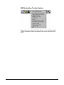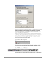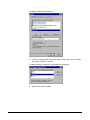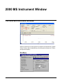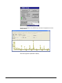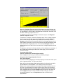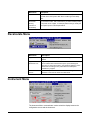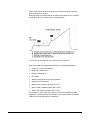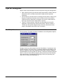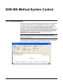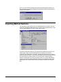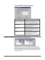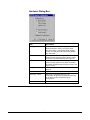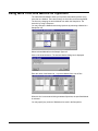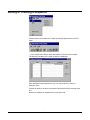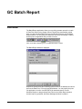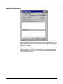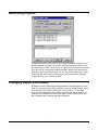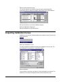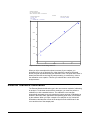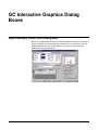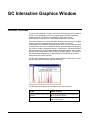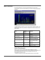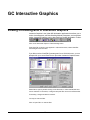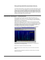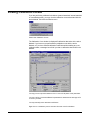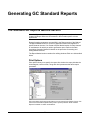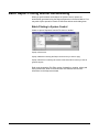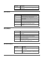
1
NOTICE: Varian, Inc. was acquired by Agilent Technologies in May 2010. This document is provided as a courtesy but is no longer kept current and thus will contain historical references to Varian. For more information, go to www.agilent.com/chem. Varian, Inc. 2700 Mitchell Drive Walnut Creek, CA 94598-1675/USA Saturn® 2000 GC/MS MS Workstation Version 6 Operation Manual ©Varian, Inc. 2003-2009 Printed in U.S.A. 03-914979-00:5 Contents Getting Started........................................................................................................................11 About this Manual/Help ............................................................................................................................................11 Additional Manuals/Help...........................................................................................................................................11 MS Workstation Toolbar ........................................................................................................13 Overview...................................................................................................................................................................13 Elements of the MS Workstation Toolbar.................................................................................................................14 Launching Applications from the MS Workstation Toolbar................................................19 Using the Application Icon Buttons...........................................................................................................................19 Using the Data File and Method Quick Link buttons ................................................................................................19 MS Workstation Toolbar Options..........................................................................................21 Moving the MS Workstation Toolbar ........................................................................................................................21 The MS Workstation Toolbar Options Menu ............................................................................................................21 2000 MS Module Control ........................................................................................................25 Starting System Control the First Time ....................................................................................................................25 Configuring the Instrument .......................................................................................................................................25 Configuring the 3800 or 3900 GC Communication (No Company Network) ...........................................................32 Configuring the GC for a Company Network............................................................................................................34 Using a Password to Protect BOOTP Settings ........................................................................................................39 Adding a GC and Varian MS to the Instrument in System Control ..........................................................................41 2000 MS Instrument Control Command Reference .............................................................47 Saturn Module Dialogs .............................................................................................................................................47 2000 Module Window ...............................................................................................................................................48 2000 MS Instrument Window .................................................................................................59 The 2000 MS Instrument Window ............................................................................................................................59 Status and Control Window ......................................................................................................................................73 3800 GC System Control Window .........................................................................................99 The Instrument Window............................................................................................................................................99 The 3800 GC Status and Control Window .............................................................................................................100 Documenting Module Information ..........................................................................................................................104 3800 GC Injecting a Single Sample .....................................................................................107 Overview.................................................................................................................................................................107 Using the Inject Single Sample Dialog Box ............................................................................................................107 Specifying the Data File Name and Path ...............................................................................................................108 1 Specifying Per-Sample Data Handling Parameters ...............................................................................................109 Specifying a RecalcList ..........................................................................................................................................110 Monitoring the Status of the Run ............................................................................................................................110 Using QuickStart.....................................................................................................................................................111 3800 GC Injecting Multiple Samples ...................................................................................113 Introduction .............................................................................................................................................................113 Using a SampleList in System Control ...................................................................................................................113 Specifying the Data File Name and Path ...............................................................................................................115 Specifying Per-Sample Data Handling Parameters ...............................................................................................116 Specifying a RecalcList ..........................................................................................................................................116 Changing Default SampleList Entries.....................................................................................................................117 Reading Vial Positions from an 8200 AutoSampler ...............................................................................................117 Monitoring the Status of Runs ................................................................................................................................118 Saving SampleLists for Later Use ..........................................................................................................................119 Using More Than One Method for Injections..........................................................................................................119 3900 GC System Control Window .......................................................................................123 The Instrument Window..........................................................................................................................................123 The 3900 GC Status and Control Window .............................................................................................................124 Documenting Module Information ..........................................................................................................................128 3900 GC Injecting a Single Sample .....................................................................................131 Overview.................................................................................................................................................................131 Using the Inject Single Sample Dialog Box ............................................................................................................131 Specifying the Data File Name and Path ...............................................................................................................132 Specifying Per-Sample Data Handling Parameters ...............................................................................................132 Specifying a RecalcList ..........................................................................................................................................133 Monitoring the Status of the Run ............................................................................................................................133 Using QuickStart.....................................................................................................................................................134 3900 GC Injecting Multiple Samples ...................................................................................137 Introduction .............................................................................................................................................................137 Using a SampleList in System Control ...................................................................................................................137 Specifying the Data File Name and Path ...............................................................................................................139 Specifying Per-Sample Data Handling Parameters ...............................................................................................140 Specifying a RecalcList ..........................................................................................................................................140 Changing Default SampleList Entries.....................................................................................................................141 Monitoring the Status of Runs ................................................................................................................................141 Saving SampleLists for Later Use ..........................................................................................................................142 Using More Than One Method for Injections..........................................................................................................142 System Control Menus.........................................................................................................145 File Menu ................................................................................................................................................................145 Edit Menu................................................................................................................................................................146 Inject Menu .............................................................................................................................................................147 Automation Menu....................................................................................................................................................147 Recalculate Menu...................................................................................................................................................148 Instrument Menu.....................................................................................................................................................148 Windows Menu .......................................................................................................................................................149 Help Menu ..............................................................................................................................................................150 2 System Control Toolbar .......................................................................................................151 Main Toolbar...........................................................................................................................................................151 2000 MS Method Basic Scan Functions .............................................................................153 Introduction .............................................................................................................................................................153 2000 MS Method Chemical Ionization .................................................................................155 Introduction .............................................................................................................................................................155 The Chemical Ionization Scan Function.................................................................................................................155 Ion Formation By Chemical Ionization....................................................................................................................157 The CI Parameters .................................................................................................................................................158 Chemical Ionization Using Fixed Parameters ........................................................................................................162 Using Liquid CI Reagents.......................................................................................................................................162 Adjusting the CI Reagent Gas Pressure for Gases Other Than Methane .............................................................165 Tuning for CI Operation ..........................................................................................................................................166 Low-Pressure CI vs. High Pressure CI...................................................................................................................166 Recommended Reading.........................................................................................................................................167 2000 MS Method Command Reference...............................................................................169 Spreadsheet editing................................................................................................................................................169 The CI Parameters .................................................................................................................................................175 CI Fixed Parameters...............................................................................................................................................176 Ion Storage (SIS) Parameters ................................................................................................................................177 Customize SIS ........................................................................................................................................................177 The MS/MS Ion Prep Method .................................................................................................................................178 The MS “q” Calculator ............................................................................................................................................178 Ion Preparation MS/MS ..........................................................................................................................................183 MSn .........................................................................................................................................................................185 2000 MS Method Electron Ionization ..................................................................................189 The Electron Ionization Scan Function with Automatic Gain Control (AGC) .........................................................189 Ion Formation..........................................................................................................................................................190 AGC Prescan..........................................................................................................................................................190 Mass Scanning .......................................................................................................................................................191 Basic Equation of the AGC Software .....................................................................................................................192 Software Parameters..............................................................................................................................................193 2000 MS Method Ion Preparation ........................................................................................199 The Ion Preparation Method...................................................................................................................................199 Theory of Operation of the SIS Option ...................................................................................................................201 Selected Ion Storage (SIS) Parameters .................................................................................................................202 Customize SIS ........................................................................................................................................................203 Tips for Using SIS...................................................................................................................................................205 The MS “q” Calculator ............................................................................................................................................205 2000 MS Method MS/MS Option: Theory of Operation .....................................................207 Overview.................................................................................................................................................................207 The MS/MS Ion Prep Method .................................................................................................................................212 The MS “q” Calculator ............................................................................................................................................214 Customize Non-resonant Method...........................................................................................................................214 Customize Resonant Method ................................................................................................................................217 3 Tandem Mass Spectrometry (MS/MS) ...................................................................................................................219 Automated Methods Development .........................................................................................................................221 MS/MS ....................................................................................................................................................................224 Unit Resolution Selected Ion Storage ....................................................................................................................224 MS/MS/MS..............................................................................................................................................................224 2000 MS Method Section......................................................................................................227 Overview.................................................................................................................................................................227 Using Star Assistant to Create a New Method .......................................................................................................227 The Method Builder Window ..................................................................................................................................230 The 2000 MS Method Windows .............................................................................................................................231 The Flow Sampling Segment .................................................................................................................................233 2000 MS Method System Control ........................................................................................235 The Startup Method ................................................................................................................................................235 Editing Methods from the Saturn Status and Control Window ...............................................................................236 Changing Method End Time from the Saturn Control and Status Window............................................................236 Importing Method Sections.....................................................................................................................................237 Deleting Method Sections.......................................................................................................................................238 Printing the Method ................................................................................................................................................239 Password Protecting a Method ..............................................................................................................................239 3800 GC Method Command Reference...............................................................................241 3800 GC AutoSampler ...........................................................................................................................................241 3800 GC Sample Delivery ......................................................................................................................................248 3800 GC Injector ....................................................................................................................................................249 3800 GC Flow/Pressure .........................................................................................................................................253 3800 GC Column Oven ..........................................................................................................................................256 3800 GC Detector...................................................................................................................................................257 3800 GC Output......................................................................................................................................................265 3800 GC Data Acquisition ......................................................................................................................................266 3800 GC Method Section......................................................................................................267 Overview.................................................................................................................................................................267 Using Star Assistant to Create a New Method .......................................................................................................267 The Method Builder Window ..................................................................................................................................270 The 3800 GC Method Windows .............................................................................................................................271 Sample Delivery Window........................................................................................................................................274 Injector Window ......................................................................................................................................................276 Flow/Pressure Window...........................................................................................................................................281 Column Oven Window............................................................................................................................................285 Detector Window ....................................................................................................................................................286 Output Window .......................................................................................................................................................294 Data Acquisition Window........................................................................................................................................295 Autosampler Window..............................................................................................................................................296 Auto-Configuring the Method to Match the 3800 GC Hardware ............................................................................297 Uploading the Method from the 3800 GC...............................................................................................................297 The Startup Method ................................................................................................................................................298 Editing Methods from the 3800 Status and Control Window..................................................................................298 Importing Method Sections.....................................................................................................................................299 Deleting Method Sections.......................................................................................................................................300 Printing the Method ................................................................................................................................................301 Password Protecting a Method ..............................................................................................................................301 4 3800 GC System Control Command Reference .................................................................303 Status and Control Window ....................................................................................................................................303 Setup Ethernet Ports Dialog Box............................................................................................................................327 8400/8410 SampleList Window Extensions ...........................................................................................................330 3900 GC Method Command Reference...............................................................................333 3900 GC AutoSampler ...........................................................................................................................................333 3900 GC Injector Section .......................................................................................................................................341 3900 GC Flow/Pressure Section ............................................................................................................................343 3900 GC Column Oven Section .............................................................................................................................344 3900 GC Method Section......................................................................................................345 Overview.................................................................................................................................................................345 Using Star Assistant to Create a New Method .......................................................................................................345 The Method Builder Window ..................................................................................................................................348 The 3900 GC Method Windows .............................................................................................................................349 GC Control Window................................................................................................................................................352 Autosampler Window..............................................................................................................................................356 Auto-configuring the Method to Match the 3900 GC Hardware .............................................................................357 Uploading the Method from the 3900 GC...............................................................................................................357 The Startup Method ................................................................................................................................................358 Editing Methods from the 3900 Status and Control Window..................................................................................358 Importing Method Sections.....................................................................................................................................359 Deleting Method Sections.......................................................................................................................................360 Printing the Method ................................................................................................................................................362 Password Protecting a Method ..............................................................................................................................362 3900 GC System Control Command Reference .................................................................363 Status and Control Window ....................................................................................................................................363 Setup Ethernet Ports Dialog Box............................................................................................................................377 8200 AutoSampler Instrument Control Command Reference ..........................................381 8200 AutoSampler Status and Control Window .....................................................................................................381 8200 SampleList Window Extensions ....................................................................................................................385 8200 Method Command Reference .....................................................................................389 8200 Configuration Window ...................................................................................................................................389 Automated MS Report Generation ......................................................................................393 Overview.................................................................................................................................................................393 Automation File Editor Command Reference ....................................................................395 Menus .....................................................................................................................................................................395 Main Toolbar...........................................................................................................................................................397 Open Automation File Dialog Box ..........................................................................................................................398 Save Automation File As Dialog Box......................................................................................................................399 Print Setup Dialog Box ...........................................................................................................................................400 Edit Notes Dialog Box.............................................................................................................................................401 RecalcList Window .................................................................................................................................................402 SampleList Window ................................................................................................................................................408 5 Sequence Window..................................................................................................................................................414 Automation File Editor .........................................................................................................415 Overview.................................................................................................................................................................415 Accessing the Automation File Editor.....................................................................................................................415 Editing or creating a RecalcList..............................................................................................................................415 Editing or creating a SampleList.............................................................................................................................417 Specifying the Data File Name and Path ...............................................................................................................419 Specifying Per-Sample Data Handling Parameters ...............................................................................................420 Specifying a RecalcList ..........................................................................................................................................421 Changing Default SampleList Entries.....................................................................................................................421 Using More Than One Method for Injections..........................................................................................................422 Editing or Creating a Sequence .............................................................................................................................423 GC Batch Report...................................................................................................................425 Overview.................................................................................................................................................................425 Method Selection ....................................................................................................................................................426 Generating Reports ................................................................................................................................................427 Changing Report Commands .................................................................................................................................427 GC Data Handling Calibration .............................................................................................429 Types of Calibration................................................................................................................................................429 Preparing the Method for Calibration .....................................................................................................................429 Automated Calibration ............................................................................................................................................430 Inspecting Calibration Curves ................................................................................................................................431 Generating Calibration Block Reports ....................................................................................................................433 Calibration Verification............................................................................................................................................434 GC Data Handling Fundamentals ........................................................................................435 Introduction .............................................................................................................................................................435 Performing a Pilot Run ...........................................................................................................................................435 Peak Detection .......................................................................................................................................................436 Identifying Peaks ....................................................................................................................................................439 Building a Calibration Curve ...................................................................................................................................439 External Standard Calibration.................................................................................................................................440 Internal Standard Calibration..................................................................................................................................441 Normalized Percent Calibration..............................................................................................................................441 Choosing a Calibration Type ..................................................................................................................................441 GC Data Handling Method Command Reference...............................................................443 Integration Parameters ...........................................................................................................................................443 Peak Table..............................................................................................................................................................445 Calibration Setup ....................................................................................................................................................447 Calibration Curve Window ......................................................................................................................................450 Verification Setup....................................................................................................................................................454 Time Events Table..................................................................................................................................................455 GC Interactive Graphics Dialog Boxes ...............................................................................459 Open Multiple Data Files Dialog Box......................................................................................................................459 Open Method File Dialog Box.................................................................................................................................462 Open Original/Recalc Dialog Boxes .......................................................................................................................463 6 Save Method As Dialog Box...................................................................................................................................464 Saturn Printer Setup Dialog Box.............................................................................................................................465 Preferences Dialog Box..........................................................................................................................................465 Reintegration List Dialog Box .................................................................................................................................471 Fill Peak Table Window ..........................................................................................................................................473 Exact View Dialog Box ...........................................................................................................................................474 GC Interactive Graphics Menus ..........................................................................................475 File Menu ................................................................................................................................................................475 Edit Menu................................................................................................................................................................476 View Menu ..............................................................................................................................................................476 Results Menu..........................................................................................................................................................477 Edit Method Menu...................................................................................................................................................478 Help Menu ..............................................................................................................................................................479 GC Interactive Graphics Toolbars.......................................................................................481 Toolbar Overview ...................................................................................................................................................481 Main Toolbar...........................................................................................................................................................481 Method Quick Link Toolbar.....................................................................................................................................482 Chromatogram Toolbar ..........................................................................................................................................482 GC Interactive Graphics Window ........................................................................................485 Locator Window ......................................................................................................................................................485 Main Window ..........................................................................................................................................................486 Info-Panels..............................................................................................................................................................489 Visual Method Edit Window....................................................................................................................................491 GC Interactive Graphics.......................................................................................................497 Viewing Chromatograms in Interactive Graphics ...................................................................................................497 Elements of the Interactive Graphics Window........................................................................................................498 Changing Viewing Options .....................................................................................................................................501 Selecting a Method .................................................................................................................................................504 Changing the Data Handling Parameters...............................................................................................................507 Filling the Peak Table .............................................................................................................................................510 Interactive Editing of Timed Events ........................................................................................................................511 Moving Peak Start and End Points.........................................................................................................................513 Calculating Results.................................................................................................................................................513 Viewing Results ......................................................................................................................................................515 Viewing Calibration Curves ....................................................................................................................................516 Printing and Copying the Chromatogram Display ..................................................................................................517 GC Standard Report Method Command Reference...........................................................519 Print Options ...........................................................................................................................................................519 Results Format .......................................................................................................................................................521 Chromatogram Format ...........................................................................................................................................522 Calibration Block Report Format ............................................................................................................................524 Generating GC Standard Reports .......................................................................................525 The Standard GC Reports Method Section............................................................................................................525 Automated Report Generation................................................................................................................................528 Automated Printing to Multiple Printers ..................................................................................................................529 7 Batch Report Printing without Recalculating ..........................................................................................................530 Viewing a Report for a Single Run .........................................................................................................................531 Method Builder Dialog Boxes..............................................................................................535 Create/Open Method File Dialog Box.....................................................................................................................535 Open Method File Dialog Box.................................................................................................................................536 Save Method File As Dialog Box ............................................................................................................................537 Add Password Dialog Box ......................................................................................................................................538 Change Password Dialog Box................................................................................................................................539 Print Method Sections Dialog Box ..........................................................................................................................540 Star Printer Setup Dialog Box.................................................................................................................................541 Delete Method Sections Dialog Box.......................................................................................................................542 Import Method File Sections Dialog Box ................................................................................................................543 Star Assistant Wizard .............................................................................................................................................543 Method Builder Menus .........................................................................................................549 File Menu ................................................................................................................................................................549 Edit Menu................................................................................................................................................................550 View Menu ..............................................................................................................................................................550 Window Menu .........................................................................................................................................................550 Help Menu ..............................................................................................................................................................551 Method Builder Toolbars .....................................................................................................553 Overview.................................................................................................................................................................553 Main Toolbar...........................................................................................................................................................553 Directory Toolbar ....................................................................................................................................................554 Window Toolbar......................................................................................................................................................555 Method Builder Window.......................................................................................................557 Overview.................................................................................................................................................................557 Method Directory ....................................................................................................................................................558 Method Parameters ................................................................................................................................................559 Module Information Editor ...................................................................................................561 Module Information Editor ......................................................................................................................................561 Creating a Section ..................................................................................................................................................562 Deleting a Section ..................................................................................................................................................562 Renaming a Section ...............................................................................................................................................562 Adding an Entry to a Section ..................................................................................................................................563 Deleting an Entry from a Section............................................................................................................................563 Editing an Entry or Renaming an Item ...................................................................................................................563 Creating a Default Module Information Template ..................................................................................................564 Designing Documentation Structures.....................................................................................................................564 Retrieving Information from Data Files...................................................................................................................565 Commands .............................................................................................................................................................565 Dialog Boxes...........................................................................................................................................................566 Security Administration .......................................................................................................569 Overview.................................................................................................................................................................569 Passwords ..............................................................................................................................................................569 Application Locking.................................................................................................................................................571 8 File Revision Settings .............................................................................................................................................572 Standard GC Reports Command Reference ......................................................................575 File Menu ................................................................................................................................................................575 Search Menu ..........................................................................................................................................................575 Font Menu...............................................................................................................................................................575 View Menu ..............................................................................................................................................................576 Options Menu .........................................................................................................................................................576 Windows Menu .......................................................................................................................................................576 Help Menu ..............................................................................................................................................................577 Standard GC Reports Dialog Boxes....................................................................................579 Open Data File Dialog Box .....................................................................................................................................579 Print Dialog Box ......................................................................................................................................................580 Printer Setup Dialog Box ........................................................................................................................................581 Title Dialog Box.......................................................................................................................................................581 Chromatogram Options Dialog Box........................................................................................................................582 Results Options Dialog Box....................................................................................................................................584 Find Dialog Box ......................................................................................................................................................585 Standard GC Reports Format Descriptions .......................................................................587 Results Report ........................................................................................................................................................587 Verification Report ..................................................................................................................................................593 Standard GC Reports Toolbar .............................................................................................595 Main Toolbar...........................................................................................................................................................595 9 10 Getting Started About this Manual/Help This manual/help system contains information about how to acquire data, build methods, and operate the Saturn GC/MS through the Varian MS Workstation. This manual also describes the configuration of the 3800 and 3900 GCs for standard Ethernet communication with the Saturn 2000 and MS Workstation’s System Control application. Use this manual in conjunction with the other manuals supplied with your MS Workstation and your 3800 GC or 3900 GC. All of the information included in this manual is also available in the On-Line Help section of the software. Additional Manuals/Help Other sources of information are available to help you get the most from this product. 2000 GC/MS Hardware Reference Manual/Help The Hardware Reference Manual/Help system provides the necessary information for installing, maintaining, using and repairing your Saturn GC/MS System. All of the information included in this manual is also available in the OnLine Help section of the software. MS Workstation Manual/Help This Manual/Help provide a practical way to quickly learn how to perform basic tasks using the MS Workstation Software. While these tutorials use Saturn 2000 ion trap files, they can easily be adapted to your instrument configuration. 3800 and 3900 GC Operator’s Manuals These manuals are included on the Varian MS Workstation CD-ROM and describe the GC Method, instrument operation, and the process of connecting your GC to a PC or to an existing network. Context Sensitive Help The MS Data Review, Method Builder and System Control sections of the software contain Context Sensitive Help. Help can be obtained simply by positioning the mouse pointer on the item of interest, clicking the right mouse button and selecting "What's This". 11 12 MS Workstation Toolbar Overview Saturn GC/MS Workstation is a suite of applications for controlling chromatographs, collecting data from chromatograph detectors, and analyzing those data. The MS Workstation Toolbar provides quick and easy access to the Saturn GC/MS Workstation applications. When activated, the MS Workstation Toolbar behaves very much like the Windows Taskbar. It can be docked on any of the four sides of the display screen and other Windows programs will not cover or go behind it when they are opened in full screen mode. If the MS Workstation Toolbar is not already opened on your Saturn GC/MS Workstation, you can start it from the Windows Start Menu. 13 Elements of the MS Workstation Toolbar Application Buttons for immediate access to the selected application. Tooltip shows the application name when the cursor rests on the Application Button. Quick Link Buttons provide menu selections of operations to be performed on the listed file. Application Descriptions give a brief description of the application that will be opened when the cursor rests on the Application Button. 14 Application Buttons Used to monitor instrument status, perform automated injections, and perform batch recalculations. Used to view and edit instrument operation, data acquisition, and data handling methods. Used for off-line editing of SampleLists, RecalcLists and Sequences. Used to review chromatograms and spectra, perform library searches, and review and process quantitation results. Used to create, edit, and view standard MS reports. Used to create, edit, and view customized MS reports. Used to convert data files between DOS and Windows formats. Used to review standard GC chromatograms, interactively edit data handling parameters, and recalculate results. Used to preview standard chromatogram and results reports. Used to generate standard reports for a group of Data Files by dragging and dropping them on the Batch Report Window. Used to run a sample without a Sample List. Used to set Saturn GC/MS Workstation security options and passwords. In addition, other application buttons may be added to the MS Workstation Toolbar when you install additional Saturn GC/MS Workstation options, such as StarFinder and Star Custom Report Writer. 15 Quick Link Buttons Most Recently Used Data File. A menu of operations that can be performed on the Most Recently Used Data File are displayed when the button is pressed. A different data file can be selected from a list of most recently used files. Most Recently Used Method. Menu of operations that can be performed on the Most Recently Used Method will be displayed when the button is pressed. A different method can be selected from a list of most recently used methods. 16 MS Workstation Toolbar Options Right-click the bar to display the Toolbar Options. A menu of MS Workstation Toolbar configuration options and operations that may be performed will be shown. 17 18 Launching Applications from the MS Workstation Toolbar Using the Application Icon Buttons Saturn GC/MS Workstation applications appear as icon buttons on the MS Workstation Toolbar. As you move the mouse over these buttons, the name of the application is shown in a tooltip window below the cursor. Click any icon in the MS Workstation Toolbar to launch the corresponding application. Using the Data File and Method Quick Link buttons The two buttons to the right of the application buttons are Quick Link buttons. These two Quick Link buttons correspond to recently used Data Files and Methods. On each Quick Link button is the name of the file associated with that button. When you click the Quick Link button, a menu is displayed showing operations that can be performed on the corresponding file. The Quick Link buttons in the MS Workstation Toolbar are always updated with the most recently used Data File and Method. If the Data File or Method you wish to use is not displayed in the Quick Link button, you can choose from the eight most recently used files by selecting “Pick a different Data File (or Method)” from Quick Link button’s menu. 19 20 MS Workstation Toolbar Options Moving the MS Workstation Toolbar The MS Workstation Toolbar can be moved to any edge of the Windows screen. Click a portion of the MS Workstation Toolbar that does not contain application or Quick Link buttons and drag the toolbar to the edge of the screen that you desire. When you release the mouse, the toolbar will remain on that edge. The MS Workstation Toolbar remembers its location the next time it is started. Additionally, you can display the MS Workstation Toolbar as a Windows Taskbar icon. To do so, select “Move to Windows Taskbar” from the MS Workstation Toolbar options menu. Taskbar icons appear in the lower right (or bottom) of the Windows Taskbar (the bar on which the “Start” button appears). When displayed as a Taskbar icon, the toolbar no longer takes up space on the screen. When you click the MS Workstation Toolbar icon, the options menu is displayed. The MS Workstation Toolbar Options Menu When you move the mouse over an area of the MS Workstation Toolbar not containing application or QuickLink buttons, you may right-click to display an option menu. 21 Move to Windows Taskbar You can display the MS Workstation Toolbar as a Windows Taskbar icon. Taskbar icons appear in the lower right (or bottom) of the Windows Taskbar (the bar on which the “Start” button appears). When displayed as a Taskbar icon, the toolbar no longer takes up space on the screen. When you click the MS Workstation Toolbar icon, the options menu is displayed. Show/Hide Applications on Toolbar Selecting this option displays the Show and Hide Applications on Toolbar dialog box. This dialog box allows you to select which Saturn GC/MS Workstation applications are represented by icons on the MS Workstation Toolbar. The top list box shows all applications that are currently displayed in the toolbar. The bottom list shows all applications that are installed but not displayed in the toolbar. To remove an icon from the toolbar, select it from the top list and click Remove. To add an icon to the toolbar, select it from the bottom list and click Add. Enable/Disable Instrument Modules Selecting this option displays the Enable/Disable Instrument Modules dialog box. 22 This dialog box allows you to select which Saturn GC/MS Workstation instrument modules are available from this Workstation. When an instrument module is available, it will appear in System Control if the corresponding instrument is connected and powered-on, you will be able to create a Method section for it, and you will be able to format reports for it. The top list box shows all instrument modules that are currently installed and enabled in the Saturn GC/MS Workstation. The bottom list shows all instrument modules that are installed but not enabled. To disable an instrument module, select it from the top list and click Disable. To enable an instrument module, select it from the bottom list and click Enable. Application Descriptions When this menu item is checked, application descriptions are displayed when you move the mouse over application buttons in the MS Workstation Toolbar. Small Buttons on Toolbar When this menu item is checked, the MS Workstation Toolbar is reduced in size. 23 Run Application This hierarchical menu item lists all applications showing on the MS Workstation Toolbar. When you select an item from this list, the corresponding application is launched. Help on This hierarchical menu item lists all applications showing on the MS Workstation Toolbar. When you select an item from this list, the online help corresponding to the application is displayed. Pick Data File for Quick Link Button This hierarchical menu item lists the eight most recently used Data Files in order of use. When you select a Data File from this list, the Data File currently displayed in the Quick Link button is changed to the selected file. Pick Method for Quick Link Button This hierarchical menu item lists the eight most recently used Methods in order of use. When you select a Method from this list, the Method currently displayed in the Quick Link button is changed to the selected file. Help on MS Workstation Toolbar Displays the help you are now using. Product Support Web Site If you have Internet access and a web browser installed on your computer, this option will automatically open the Saturn GC/MS Workstation Product Support Web Site. Here you will find the latest software and documentation updates for the Saturn GC/MS Workstation suite of products, along with additional notes, tips, and answers to frequently asked questions. You may wish to visit this site periodically to see if new information is available that may be pertinent to you. About MS Workstation Toolbar Displays the About Box for the MS Workstation Toolbar. The About Box contains information about the software version, installation information, and a list of the instrument control modules that you have installed. Quit Quits the MS Workstation Toolbar application. If you elected to run the MS Workstation Toolbar automatically when Windows starts, the MS Workstation Toolbar will reappear the next time you start Windows. 24 2000 MS Module Control Starting System Control the First Time Before you enter System Control for the first time, confirm that the proper instrument modules have been enabled and that any instrument modules that are not part of the system have been disabled. To enable or disable instrument modules refer to the section of the MS Workstation Toolbar, Enable/Disable Instrument Modules. Configuring the Instrument Before beginning the configuration process, you should know whether you will be attaching your Workstation and 3800 or 3900 GC to a company network or an isolated network only used for instrument control. If you have a Network Administrator on site, you may wish to ask which configuration is recommended. Use this table to determine the order in which you should read the following sections. 1. If an Ethernet card has not been installed and configured on your PC, read Installing and Configuring the Ethernet Card in Your PC and one of the following: No Company Network: Configuring TCP/IP Parameters with no Company Network. Company Network: Configuring TCP/IP Parameters for a Company Network. 2. Read Connecting Your 3800 or 3900 GC to Your PC or Network. 3. If you have not already installed the Varian MS Workstation, do so before proceeding. No Company Network: Read Configuring the 3800 or 3900 GC Communication (No Company Network). Company Network: Read Configuring the GC for a Company Network. 4. Continue reading the rest of the sections, starting with Adding a GC and Varian MS to the Instrument in System Control. 5. Installing and Configuring the Ethernet Card in Your PC. NOTE: The following section describes a procedure that is relatively generic; consult your Windows documentation and that of the Ethernet card’s manufacturer for more detailed explanations. 25 Refer to the installation instructions packaged with your Ethernet card for information on installing the Ethernet card in your computer. Before proceeding, your Ethernet card should be recognized by your Windows version. When done, the Network Neighborhood icon should appear on your Windows desktop. NOTE: For the following procedure, the use of disks other than the ones that were used for the original Windows installation may result in a Ethernet driver version mismatch that keeps Windows from starting. Should this occur, it may be necessary to remove the Ethernet Board from the computer to remove the incorrect Ethernet drivers. You must configure your computer’s network settings to allow communication with the 3800 or 3900 GC. You do so by running the Windows Control Panel. 1. Run the Control Panel by selecting it from the Start menu (under Control Panel or Settings). The Control Panel window is displayed. 2. Double-click the Network icon to set your Network options. 26 The Network dialog box is displayed. 3. If TCP/IP is already listed in the list of network components, skip to the Note after step 5, otherwise, click Add. The Select Network Component Type dialog box is displayed. 4. Select Protocol and click Add. 27 The Select Network Protocol dialog box is displayed. 5. Select Microsoft as the manufacturer. Select TCP/IP as the protocol. Click OK. The protocol is added to your installed network Component list. NOTE: If you are not connecting your Workstation to a company network (that is, you are not assigned an IP address by a Network Administrator), follow the next three steps. If you are connecting your Workstation to a company network, skip to Configuring the GC for a Company Network. Configuring TCP/IP Parameters with no Company Network The following three steps assume you have completed steps 1 through 5 from the previous procedure. 1. Select TCP/IP from the network components list and click Properties. The TCP/IP properties dialog box is displayed. 28 Enter an IP address in the range 10.2.128.1 through 10.255.255.254. Note that if you are adding more than one Workstation to this network, each Workstation PC must have a unique IP address within this range. The Subnet Mask will be automatically set to 255.0.0.0. Do not change this value. 29 Ensure that no entries have been made in your Gateway, and that Domain Name Server (DNS) and WINS Configuration have been disabled. These entries are not used in an isolated network and may cause problems if they are present. Delete any settings that may have been entered from a previous configuration. 2. Click OK. Reboot Windows for the changes to take affect. NOTE: Refer to Communication Problems in the Diagnostic and Troubleshooting section for information about diagnostic tools to verify that your network installation is correct. Configuring TCP/IP Parameters for a Company Network The following three steps assume you have completed steps 1 through 5 from the previous table. 3. Select TCP/IP from the network components list and click Properties. The TCP/IP properties dialog box is displayed. Enter the IP address to be used by this Workstation. Contact your Network Administrator (or whoever assigns IP addresses in your network) to get the appropriate address. Note that each Workstation PC must have a unique IP address. Enter the appropriate Subnet Mask to be used with this IP address. 4. Your Network Administrator may instruct you to obtain an IP address automatically by selecting the appropriate radio button. 30 Contact your Network Administrator (or whoever assigns IP addresses for your network) to see what the appropriate settings are for your Gateway, and whether Domain Name Server (DNS) and WINS Configuration are needed. 5. Your Network Administrator may also instruct you to specify parameters in the Bindings and Advanced tabs. 6. Click OK. Reboot Windows for the changes to take affect. NOTE: Refer to Communication Problems in the Diagnostic and Troubleshooting section for information about diagnostic tools to verify that your network installation is correct. Connecting Your 3800 or 3900 GC to Your PC or Network Refer to the Installation Instructions for the 3800 GC Communications Board (packaged with the 3800 GC Communications Kit) for details on adding the communications board to your 3800 GC (if not previously installed). Also, refer to the “Communications” section of the 3800 GC Operator’s Manual or 3900 GC Operator’s Manual for instructions on connecting your GC to the PC or a company network. Before proceeding, your GC should be connected to your PC or network. 31 Configuring the 3800 or 3900 GC Communication (No Company Network) Use the following instructions if either a 3800 or 3900 GC and Varian MS Workstation PC are being connected to an isolated network, that is, a network dedicated to Varian MS Workstations and the instruments they control. In this case, a Network Administrator will not be involved in assigning IP addresses. NOTE: If you are connecting your 3800 GC and Varian MS Workstation PC to a multi-purpose company network managed by a Network Administrator, refer to Configuring the 3800 or 3900 GC Communication (No Company Network). You may connect one 3800 GC directly to one Workstation… After you have configured your computer’s network settings start System Control. Click System Control/ Automation. When System Control has started for the first time, the Star Assistant Communication Configuration Wizard will appear to guide you through the setup and network connections of your 3800 GC. Use the following procedure for configuring the IP address for your GC. The first time the Star Assistant guides you through the setup of your 3800 you will get the following messages: Read the description presented in each window and click Next. 32 From the Setup Ethernet Ports, click Setup for IP Address Management [BOOTP Server]. Click Setup. When the Setup BOOTP Server dialog box is displayed, turn on the 3800 or 3900 GC that has been connected to the network. NOTE: If more than one Workstation is being connected on the same network, only one Workstation should manage the IP addresses for all GCs connected (all others should have the Manage IP addresses from this Workstation checkbox unchecked). If more than one Workstation is managing IP addresses, naming conflicts may arise. As the GC is powered on, an entry is added to the table. For each entry, an IP address is automatically assigned. For each GC, you provide a host name that will be used to identify it in the Varian MS Workstation. 33 Click the Manage IP addresses from this Workstation checkbox to manage your GC’s IP address from this Workstation. As the GC is turned on, its Ethernet address is added to the list.. The IP address is automatically generated. Enter a host name for each GC. This name is used to identify the GC in the Workstation. You cannot connect to a GC until you provide it a name. Click OK after entering host names for each GC. NOTE: Proceed to Using a Password to Protect BOOTP Settings. Configuring the GC for a Company Network Use the following instructions if either a 3800 or 3900 GC and Varian MS Workstation PC are being connected to a company network, that is, a multipurpose network used for services in addition to instrument control. In this case, a Network Administrator will be involved in assigning IP addresses. If the GC and Varian MS Workstation computer are the only devices being connected together, refer to Configuring the 3800 or 3900 GC Communication (No Company Network). You may connect virtually any number of 3800 and 3900 GCs and any number of Varian MS Workstation computers to a company Ethernet network. Depending upon your network configuration, all Varian MS Workstations will be able to control all 3800 and 3900 GCs on the network. After you have configured your computer’s network settings start System Control. 34 Click System Control/Automation. When System Control has started for the first time, the Star Assistant Communication Configuration Wizard will appear to guide you through the setup and network connections of your GC. NOTE: Before proceeding with this section, consult your Network Administrator about whether a central BOOTP Server is available on the network. 1. If IP addresses are managed by a central BOOTP Server, then proceed to Specifying IP Addresses from a Central BOOTP Server. 2. If IP addresses are specified by a Network Administrator but not centrally managed, then continue reading Specifying IP Addresses from System Control. Specifying IP Addresses from System Control The Varian MS Workstation can be used to specify IP addresses to 3800 and 3900 GCs attached to the network. Use the following procedure to manage IP addresses form System Control. The first time the Star Assistant guides you through the setup of your GC you will get the following messages: Read the description and click Next. 35 From the Setup Ethernet Ports dialog box select Setup to display the BOOTP Server dialog box. Select Setup to display the BOOTP Server dialog box. The BOOTP Server dialog contains a table listing all 3800 and 3900 GCs to which IP addresses may be assigned. 36 NOTE: If more than one Workstation is being connected on the same network, only one Workstation should manage the IP addresses for all GCs connected (all others should have the Manage IP addresses from this Workstation checkbox unchecked). The Workstation acting as BOOTP Server must remain running all the time to allow other Workstations to connect to GCs. If more than one Workstation is managing IP addresses, naming conflicts may arise. Check this box to enable the BOOTP Server. If 3800 or 3900 GCs are already connected to the network and powered on, their Ethernet addresses will appear in this table. You must enter a name for each GC. The IP address will not be assigned to the GC until a name is entered. You may manually assign any IP address to any GC. When this item is selected, type the IP addresses directly into the table. Select OK when all addresses and names have been entered. 37 When the Assign # IP addresses starting from: #.#.#.# radio button is selected, the bottom portion of the dialog changes. You may select to consecutively assign IP addresses beginning from a particular address. Enter the number of IP addresses you want to assign automatically. Enter the starting address here. As 3800s are powered on, IP addresses are automatically assigned starting with this address. NOTE: Proceed to Using a Password to Protect BOOTP Settings. Specifying IP Addresses from a Central BOOTP Server If IP addresses are managed by a Network Administrator from a central source, the 3800 and/or 3900 GCs must be added to the list of devices requiring IP addresses. IP addresses must be assigned to GCs using a BOOTP Server. A BOOTP Server lists Ethernet addresses (which are unique to each communication card installed in each 3800 and 3900 GC) along with the IP addresses that are to be assigned to the corresponding device. You may obtain the Ethernet address for each GC from the GC’s front panel or the label on the Ethernet card within the 3800 GC. Turn on the 3800 GC and press any key to allow it to start in local mode. The Ethernet address will be automatically loaded into the BOOTP Server list for 3900 GCs. PAGE START CURSOR STOP NOT READY READY RUN TABLE EDIT NEW LINE DELETE LINE CLEAR TABLE METHOD ACTIVATE EDIT MENU ENTRY HELP UNDO AUTOMATION SINGLE METHOD METHOD SEQUENCE SELECT/ EDIT GC CONTROL PRIORITY SAMPLE SUSPEND RESUME INSTRUMENT SAMPLE DELIVERY INJECTOR FLOW/ PRESSURE COLUMN OVEN DETECTOR OUTPUT STATUS SETUP MENU INCR DECR ENTER When the GC has completed its initialization process, press the menu button. 38 The Instrument menu is displayed. Press 1 to select the Remote/ Local Control screen. The Ethernet address, IP address and Alias (which may not yet be assigned) are displayed. ACTIVE METHOD EDIT METHOD Method 1 Method 1 CTRL RUN TIME END TIME 0.00 20.00 REMOTE / LOCAL CONTROL Enable Ethernet Address: XX:XX:XX:XX:XX:XX IP Address: XXX.XXX.XX.XXX Alias: 3800A Use the Ethernet address shown here when setting up the BOOTP Server. The IP Address and Alias (host name) are assigned by the BOOTP Server. If the BOOTP Server that you are using automatically updates its table with Ethernet addresses broadcast by devices on the network, then the Ethernet addresses from 3800 and 3900 GCs connected to your network and powered on will automatically appear. Note that the frequency with which these addresses are broadcast by the GC decreases over time to a maximum rate of once per minute. This means that the BOOTP Server may not receive an Ethernet address for up to a minute from any given GC. If you are using a 3800 GC on a 2000R system and the BOOTP Server that you are using does not automatically update its table with Ethernet addresses broadcast by devices on the network, then the Ethernet address can be obtained from the label on the Ethernet card in the 3800 GC. Once you have entered the Ethernet address for each GC on the network to the BOOTP Server, power each GC off then on again. Check that the IP address shown on the front panel of each GC (in the Remote/Local Control screen) matches the intended address entered into the BOOTP Server. If they do not match, verify the Ethernet address, updating the BOOTP Server if necessary. Powering the GC off and on will update the IP address. NOTE: When IP addresses are managed from central location by a Network Administrator, the BOOTP Server on your workstation must be disabled. Verify that the Manage IP addresses from this Workstation is unchecked in the Setup Ethernet Ports dialog box. Using a Password to Protect BOOTP Settings You may wish to restrict access to the BOOTP Server dialog box to avoid inadvertent or unauthorized changes to IP address assignments. To do so, enable password protection in the BOOTP Server dialog box. If the Setup 39 Ethernet Ports dialog box is not displayed, select the Setup Ethernet Communications menu item from the Instrument menu to display the Star Assistant Communication Wizard. Click Next. Select Setup to display the BOOTP Server dialog box. The BOOTP Server dialog is displayed. Check this box to enable password protection. The next time you enter the BOOTP Server dialog box from the Setup Ethernet window, you will be prompted for a password. Enter a password here. Once successfully entered, you may change the password below. Enter a new password here twice. The initial password is blank (no password). To set your password initially, enter the desired password in the Enter new password and Re-enter new password fields. Subsequent entry into the BOOTP Server will require this password. NOTE: Refer to Recovering a Lost Password for BOOTP Server Access in the Diagnostics/Troubleshooting section for instructions on resetting the password. 40 Adding a GC and Varian MS to the Instrument in System Control Once you have configured your Workstation computer and 3800 or 3900 GC for network communication, you may select one GC to be controlled from each Varian MS Workstation. If it is not already running, start System Control. The Star Assistant Communication Configuration Wizard will be displayed if you have not yet configured your GC Ethernet connections. Click Next. Click Address to attach to a 3800 GC on the Ethernet network. When the Address button is selected, the Module Selection dialog box is displayed. Select the GC that you wish to connect to the address (44). Click OK. NOTE: If you are running on a company network, only GCs on the same local subnet appear in the Select Available Modules dialog box. To connect to a GC in a different subnet, type its IP Address directly into the IP address field in the Setup Ethernet Ports dialog box. Consult your Network Administrator about subnets on your network. After you have completed your selection, the Setup Ethernet Ports Dialog Box shows the 3800 GC connected to your Workstation. 41 This 3800 GC is connected to Port 44. The status indicates the availability of the GC. The IP address of the GC is shown here. Click OK, and wait for the 3800 to connect. When the GC connects to System Control, it will be represented by an icon at the bottom of the Configuration Window. The icon will have a label reading 3800.44, and will include the Host Name of the GC appended to the label. The number 44 is a System Control communication addresses that correspond to the Ethernet port connected to the device. The same principles are true for the 3900 GC. Modules and Instruments Defined The Varian MS system consists of two modules, the 3800 GC and the 2000 MS. Additionally, a third module is present if you have the 8200 AutoSampler (Note that the CP-8400 and CP-8410 AutoSamplers will not have a separate icon but will be included on the 3800 or 3900 Status and Control Window). These modules also have addresses and the message logs frequently refer to the module and address. The modules and allowed addresses are listed below. Module Name Address Mass Spectrometer 2000 40 Gas Chromatograph 3800 44 AutoSampler 8200 26 Other communication addresses are used for different types of communication hardware: 16,18,20,22 for Varian ADC Boards; 17,19,21,23 for Varian 3400 and 3600 GCs, and 24 - 39 for Serial Port devices. If an 8200 AutoSampler is attached to the J4-SID1 connector on the 3800 GC, the 8200 icon will also appear with the Host Name of the corresponding GC appended to the label. NOTE: Refer to the 8200/SPME AutoSampler for 3800 GC Manual for information about configuring your 8200 for use with the 3800 GC. 42 Elements of the Configuration Screen After the 3800 or 3900 connects to System Control, configure it in an Instrument by moving its icon from the bottom of the Configuration Window into the Instrument Area. System Control will remember where to put the icon the next time that the 3800 connects. If the 3800 is to be operated with an 8200, make the 8200 the AutoControl Module. Place the GC icon in the AutoControl Module if either a CP-8400 or CP8410 AutoSampler will be used with the GC. If the 3800 or 3900 is to be operated without an AutoSampler controlled from the Varian MS Workstation, leave the AutoControl Module box empty. If you are using a sampling device with the 3800, the device must be connected to the synchronization port of the GC. The Varian MS is usually configured into 2 modules, the 2000 and the GC. Additionally, an 8200 AutoSampler can also be part of the system. After each module connects to System Control, configure it in an Instrument by moving its icon from the bottom of the Configuration Window into the Instrument Areas. System Control will remember where to put the icon the next time that the system connects. 43 Instrument Parameters, Instrument Name, Operator Name, and Instrument status are listed here. AutoStart Module area. Place the 8200 AutoSampler Module icon in this box. Module icon showing that 3800 GC Module 44 has been configured to Instrument #1. Click button to enter or change the Instrument Name, Operator Name, and Maximum allowable error count. Modules that have logged in and are available for configuration into an instrument are displayed here. Once the modules are in place you are ready to proceed. Setting Instrument Parameters Some parameters used by the Instrument are set in the Instrument Parameters dialog box accessed from the Configuration window. The instrument name appears on reports and in the instrument window. The operator name appears on reports. The Ready File is used only with older Varian 44 software versions (i.e. the forth software system). When the maximum number of non-fatal errors is exceeded during automation, the automation sequence halts. Setting this value to zero disables this feature. You are optionally prompted for this information when you start an automated sequence of injections or recalculations. Running an MS Method Without a GC Method To run an MS method without the GC module or GC method, open System Control. Under the menu Instrument, select Configuration. Move the GC icon from the mid field to below the bar labeled Available Modules, by click, drag and dropping the icon . When a MS method is activated, the GC method will not be downloaded. To activate the GC and AutoSampler modules, click-drag-drop the icons into the active field. NOTE: If an AutoSampler icon is present: click, drag and drop the AutoSampler icon in the Available Modules area. 45 46 2000 MS Instrument Control Command Reference Saturn Module Dialogs Saturn Module Keypad Dialog This dialog can be hidden by clicking on Hide Keypad. 47 Spectrum Toolbar Click the green arrow t hide the toolbar. Click the upper left of the full screen display to restore the toolbar. Click full scale to normalized to chromatogram. Double-clicking the chromatogram does the same. Click to return the xy axes to the previous scale. Click spectrum plot to open a preview of the spectrum. Click scale to choose between Auto Scale and Fixed Scale Intensity. Click mass range to choose between Acquired Mass Range, Fixed Mass Range, or Maximum. Click to switch graphics or text displays of ion intensity and status information. Click select preferences to change the color of the chromatogram display, labels, axes, font, and other features. Click Report Preferences to choose the chromatogram and spectra options for the standard report. 2000 Module Window 48 Item Description Manual Control Click the Manual Control to turn on or off the trap controls (rf, Filament, and Multiplier) and to open the CI and Cal gas valves. Also adjust the rf response, the CI gas pressure, and the Cal gas pressure. This mode is also used to select the current trap filament and to adjust the axial modulation voltage. Although scans may be taken and displayed under method conditions of any one of the MS Method segments, data may not be acquired while in this mode. To acquire data, Acquisition Mode must be selected. Auto Tune Tune the instrument, including the multiplier setting, mass calibration, and trap function calibration. Temperatures Change the temperature of the ion trap or transfer line. Do bakeout to remove volatile materials absorbed on electrode surface. Diagnostics Check the system for status and faults. Shutdown Shutdown for routine maintenance or for an extended period. Acquisition Acquire data for a single sample or an automated list . Manual Control Ion trap schematic Item Description On/Off Turn on or off the ion trap (the filament, rf and multiplier). Turn on or off the rf Turn on or off the filament. Turn on or off the multiplier. Open the valve to turn on the CI gas. Open the valve to turn on the Cal gas. Hide Keypad Remove the upper portion of the screen display so that the lower portion is expanded. Display Selection Select from to view the spectrum in profile or centroid mode. 49 Instrument Settings Item Description Method button Opens the Method Editor program. Segment # box Select the current segment of the active method. Scan Mode Ionization mode of the current segment, such as EI-Auto. Ion Prep. Ion preparation method of the current segment, such as MS/MS. Setpoints tab Item Description Filament Selection Click to select the current filament. Saturn has 2 filaments so the system can be used if one burns out. Axial Modulation Voltage Select the voltage to apply to the upper end caps. Recalibrate the mass axis when you change this value. Apply button Apply changes you make to the Axial Modulation Voltage. If the voltage edit control has the focus, press enter to apply the changes. Adjustments tab 50 Item Description Adjust Cal Gas Click to adjust the cal gas pressure. Adjust rf Ramp Change the rf setting for the instrument by turning the screw at the bottom front panel. Adjust Set the proper CI reagent pressure for CI analysis. The pressure is very dependent on the reagent gas used. Reagent Gas Selection Box Choose which CI gas you are using. Done Used when you complete your adjustment. Status Item Description Mode State Indicates what function the Saturn MS is currently performing, such as scanning or adjusting cal gas. Fault State Indicates if a fault has occurred. Ion Time Indicates the ionization time of the last scan. Ion Count Indicates the ion count of the last scan. Auto Tune 51 Item Description Start Auto Tune Begins the event sequence that will tune the instrument. Only checked boxes will be executed. Reset Stops the auto tune process. Continue Starts the next selected function if the single step option has been checked. Hide Keypad Causes upper portion of the screen to be removed so that the lower portion can be expanded in the display. Display Selection Select the display. Method Item Description Air/Water Check Measures the air and water content of the trap, to determine if there is a leak. Electron Multiplier Tune Autoset the electron multiplier voltage. FC-43 Mass Calibration Calibrate the mass axis. Choose Straight Line or FC-43. Trap Function Calibration Calculate the waveforms for CI, MS/MS and SIS. Single Step Observe each step in the auto tune process. Use Continue to proceed after each step. Set Points 52 Item Description Electron Multiplier Voltage Manual adjustment of the Final Gain Setting determine from the Auto Tune check. SIS Amplitude Adjust Factor Adjust each trap system for optimum ion sensitivity and ejection. The voltage adjustment range is between 50 to 200%. The default is 100%. Temperatures Item Description Start Bakeout Execute the bakeout conditions, which removes volatile material from the ion trap surface. Reset End a bakeout before the specified time. Hide Keypad Hide the upper portion of the screen and expand the lower. Analysis Conditions Set temperature for trap, manifold and transfer line. Click Apply to initiate conditions. Bake out Conditions Hold Time specifies the number of hours for bake out. Under Trap, set the bake out temperature, such as 220 C. The manifold bakeout temperature is fixed. The transfer line bakeout temperature matches the analysis temperature. Diagnostics Mode 53 Item Description Start Click Start to execute the desired test Reset Cancel a test executed with Start. System Test Item Description Run To Completion Click to run all tests without stopping. Halt On Error Halts the system checks when an error is detected. Detailed test of the heater zones Item Description Trap Tests the Ion Trap heater element May take up to 13.5 hours to complete. Manifold Tests the Manifold Heater element. Transfer Line Tests the Transfer Line heater element. 54 Monitor Window Item Description Multiplier check box Display the voltage (center left) on the multiplier when on. rf check box For Service Engineers. Filament check box Display the status of the system filaments (upper right). Ion gauge check box View the vacuum status using the filament selected by the Filament Radio Button. Filament Select a filaments and view the ion gauge vacuum system test. Shows current temperature readings for each zone 55 Shutdown Mode Item Description Shutdown button Shuts down the system in an orderly manner. The pump speed is slowly reduced and the heaters are turned off so that the system slowly cools. Reset button Brings the system back to a ready state if the Shutdown procedure was started. This restarts the pumps and turns on the heaters. Diffusion Pump Shutdown Sequence NOTE: The Diffusion Pump System shutdown sequence takes at least 30 minutes: The Saturn GC/MS heaters are turned OFF. The GC temperature zones should be cooled downed before maintenance is performed. The diffusion pump heater is turned OFF while the Peltier Baffle cooler is kept on. The DIFFUSION PUMP STATUS changes from NORMAL to COOLING. After 15 minutes, when there is no pump vapor to contaminate the system, the Peltier Baffle cooler is turned OFF. After another 15 minutes, the cooler has warmed to the point that it won’t condense water vapor, and the pump is considered to be off. The DIFFUSION PUMP STATUS then changes from COOLING to OFF. NOTE: If the word “FAULT!” is displayed in the Vacuum Status box, click Diagnostics for detailed information. The Vacuum Status represents the state of the diffusion pump. To precisely identify the problem, the USER should go to the Diagnostics mode and run "System Test to Completion”. Fault messages may appear on startup or during normal operation. 56 Turn OFF main power by placing switch at rear of system into OFF (down) position. Manually vent the system for at least 5 minutes using the lever on front panel. NOTE: DO NOT ATTEMPT to VENT SYSTEM by any other method (via transfer line, foreline vacuum clamps, etc.). Rapid, improper venting of the system will cause diffusion pump fluid to backstream into the manifold and ion trap. Maintenance procedures SHOULD NOT BE attempted until the shutdown program has finished! Acquisition Mode Item Description Start Acquisition button Click to start the analysis. Reset button Will end the acquisition and reset the conditions to their initial conditions. End time button Click to increase or decrease the end time of the analysis. Hide Keypad button Causes the upper portion of the screen to be removed so that the lower portion can be expanded in the display. Display Box Selector Allows you to choose among chromatogram, spectra, or both. Method button Used to open the Method Editor with the active method. You can edit the method and then return to this screen for analysis. 57 58 2000 MS Instrument Window The 2000 MS Instrument Window System Control has four major sections: the System Control Menu bar, System Control Toolbar, Saturn Keypad Dialog, Chromatogram and Spectrum Toolbar, and Spectrum Display. File Menu 59 Activate Method allows you to choose a method from those already prepared. This will set the conditions for the GC, MS, AutoSampler and data handling. Other sections will also be activated if they are part of the method. Upload Active Method from Modules will allow you to get the conditions from the existing modules to be saved in a new method. Whichever method is active will now be converted to the conditions of the active modules. New Sample List allows you to open the dialog box to create a sample list. Open Sample List allows you to select and activate an existing sample list. The sample list dialog box is shown below. New Recalc List allows you to open the dialog box to create a recalculation list. Open Recalc List allows you to select and activate an existing recalculation list. The Recalc list dialog box is shown below. NOTE: You may process a Recalc List either in System Control (by clicking the Begin button) or in SaturnView. In SaturnView use the menu command Quantitation… Process/Review Recalc List to access this feature. Also note that processing of a Recalc List takes more time when done from System Control but has the advantage of allowing AutoLink functions such as automated reporting with SaturnWriter templates. New Sequence List allows you to open the dialog box to create a sequence list. Open Sequence List allows you to select and activate an existing sequence list. The sequence dialog box is shown below. 60 Edit Menu Click the Edit menu and highlight Edit Module Info. Each module in your system (3800GC, 2000MS, 8200 AutoSampler) contains its own message log and documentation screen. The Module Documentation screen shown below allows you to keep a record of performance, maintenance, hours used, or any other comments you wish to make. Use the Add, Edit, and Delete buttons to record any information you wish about the MS module. 61 Inject Single Sample Menu The command will allow you to give the sample information prior to an injection. The dialog box below will appear when this command is invoked. The 2000 module window must be in acquisition mode for the system Not Ready to convert to Ready and then a manual injection can be made. If an AutoSampler is used, click Inject in the bottom left corner. The sample type can be changed by double clicking in the field below Sample Type. The following displays your choices. The same procedure can be used for injection notes. Any notes that you wish to enter here will be saved with the data file. The AutoLink button works in the same way. Note the picture below. A command can be entered here to execute a program once the data file acquisition is completed. For example, this can be a program to activate Saturn Writer to print the sample reports. To run a SaturnWriter report in automation enter the directory path and the name of the SaturnWriter template (for example C:\VarianMS\EPA525.swt). Note that SaturnWriter templates should always be stored in the VarianWS directory. The browse command can be used to select the command executable file. Select OK when you have made your selection. 62 Automation Menu Below is a picture of the Automation pull down menu and a description of the functions. Begin Sample List will cause an automation to start at line 1 and end at the last line. Begin Sequence will allow you to change methods and sample list during an automation. An example of this might be to run a set of samples using EI and then the same set of samples using a different MS method for CI. Begin At starts an automation at a particular line and runs until the last line is completed. Suspend Automation stops an automation at its last completed sample. Resume Automation starts the automation after it has been suspended. It starts where it was suspended. Stop Automation ends the automation action. Reset Modules brings the various modules to there ready states. Enable Automated Printing allows the printer functions to work during an automation. Recalculate Menu The above picture highlights the Recalculate pull down menu. Note that recalculation may be performed here in System Control or in SaturnView under the menu command Quantitation… Process/Review Recalc List. Also note that processing of a Recalc List takes more time when done from System Control than in SaturnView but has the advantage of allowing AutoLink functions such as automated reporting with SaturnWriter templates. 63 Begin RecalcList will allow you to start an automated recalculation. A recalculation list must already be prepared and selected to do this. A New Recalc list may need to be made. Begin at Selected RecalcList Line allows you to process a recalculation list starting with a chosen line and proceeding with the rest of the list. View Calibration Curves will allow you to view any of the curves for the calibrated compounds in the active method. An example of the calibration curve screen is given below. For a complete explanation of this screen, go to the Quantitation section. Instrument Menu The pull down Instrument menu: Saturn GC/MS #1 denotes that this is the instrument configured. Configuration allow you to add new modules to the existing instrument. This is necessary if additional hardware is added such as an additional GC detector. 64 Instrument 1 Faults allows you to see if there are any faults in any of the modules contained in Instrument 1. An example of this screen is shown below. The update key will allow you to periodically check for new faults without opening and closing the dialog box. 2000 faults are not reported in this window. Setup Ethernet Communication will allow you to set up the communication between the 3800 GC and System Control. Windows Menu The pull down menu titled Windows allows you to view any of the windows associated with the system control. This list is shown in the picture below. Show Module Windows allows you to see all of the module windows that are configured in the instrument. In this example the module available is the 2000. Iconize Module Windows causes the individual module windows to become icons at the bottom of your screen. Show Automation Windows allows you to view any of the automation screens. These are the Sample list, Recalc list, and Sequence list. Arrange Icons arranges the icons, if any, in a row at the bottom of the System Control window. Sequence List allows you to display the active sequence list. Sample list allows you to display the active sample list. Recalc list allows you to display the active recalculation list. 65 Instrument 1 Status allow you to view the status of the modules connected to the system. Message Log allows you to view the event log for the MS module. The log display is shown below. All error messages for the Saturn Module will show up here. 2000 module allows you to display the Saturn module control screen. Help Menu Click an item in the Contents box to open online help. 66 In the Help dialog box, from the Index tab, you can select a particular topic. Click the selection, go to the bottom of the screen and click Display. 67 System Control Toolbar The system control toolbar is located near the top of your screen. A picture of this toolbar is displayed below. Clicking on this button will allow you to create a new automation file. Clicking on this button will allow you to select a new automation file. Clicking on this button will allow you to view/edit or print a method. Clicking this button will allow you to activate a method. Clicking on this button will allow you to edit notes for an automation file. Clicking on this button will allow you to edit module information for any module that is online such as the 2000, 3800GC, or 8200 AutoSampler. Clicking on this button allows you to inject a single sample. Clicking on this button allows you to start a recalculation list if you have one active. 68 Clicking on this button allows you to start a sample list that you have created. The list must already be selected. Clicking on this button allows you to start a sequence list that has been created. Clicking on this button allows you to suspend a list that is running. Clicking on this button allows you to begin a list. Clicking on this button is used to stop a list that is already running. Saturn Module Keypad Dialog This dialog can be hidden by clicking on Hide Keypad. Click Show Keypad to display Saturn Module Modes : Manual, Auto Tune, Temperatures, Diagnostics, Shutdown, and Acquisition. See Saturn Module Modes for details. 69 Spectrum Toolbar Click the arrow to hide the toolbar. Click the upper left of the screen to restore the toolbar. Click full scale to normalize the chromatogram in the vertical and horizontal directions. Double-click the chromatogram to do the same. Click this to return the xy axes to the previous scale. Clicking on the spectrum plot button will cause a window previewing the spectrum to be displayed. Clicking on the scale button allows you to choose between Auto Scale Intensity and Fixed Scale Intensity. Clicking on the mass range button allows you to choose between Acquired Mass Range, Fixed Mass Range, or Maximum. This button allows you to switch between graphics and text displays of ion intensity and status information. Configuring the Real-Time Chromatogram Display Before performing an analysis the MS module window must be in acquisition mode. To enter this mode, click Acquisition. During an analysis, observe the chromatogram in the system control screen. From the following list box ,select the Chromatogram, Spectrum, or both to be displayed. 70 Choosing the Chromatogram only option will allow you to see a live chromatogram as in the example below. Click Hide Keypad to expand the chromatogram. Notice in the following picture the text information at the top is hidden. To bring the keypad display back, click Show Keypad. Configuring the Real-Time Spectrum Display During an analysis it is possible to observe the spectrum in the system control screen. However, if there are insufficient processor resources, the spectrum control will not be updated until those resources become available. Selecting the time selector mode in the chromatogram display will also stop the real-time update of the spectrum display. In the picture below the drop down list box allows the selection of Chromatogram, Spectrum, or both to be displayed. 71 Choosing the Spectrum only will allow you to see a live spectrum as in the example below. Click hide keypad to expanded the display. 72 Click Show Keypad to display the keypad. Status and Control Window You are now ready to program the GC/MS to perform fully automated data acquisition. Initially the MS Module Window will look similar to the figure below. If you do not see this screen, go to the pull down menu labeled Instrument, and select the item “Saturn GC/MS”. The upper left side of the window shows the ion trap schematic, which allows the ion trap to be turned on. If the trap is displayed in red, it is currently disabled. The trap is disabled if the current segment is a filament/multiplier delay segment, one with an ionization mode of none, or if a fault has occurred. If the ion trap icon is not currently disabled, clicking in the center of the ion trap will turn on the trap. The black schematic will turn green to denote that it is on, as displayed below. 73 You must select a method segment that is not a Filament/multiplier delay segment for the ion trap to be enabled. This method and segment selection is located in the center of the screen. This center section deals with the active method and the instrument set points. The ion trap symbol is a pictorial representation of the ion trap showing the endcaps (two horizontal curved lines), the rf-voltage ring electrode (two vertical curved lines), the electron multiplier (a curved cone), the filament (a triangle), the tank for the CI reagent gas, and the reservoir for the calibration compound. By clicking on the appropriate part of the ion trap symbol, or by clicking on the corresponding button, you can turn on and off the various parameters shown in the symbol (i.e. click triangle to turn on filament). Click in the center of the trap and the Cal Gas bulb, a spectrum of PFTBA will be displayed. Method Now notice the three tabs in the center of the System Module: Method, SetPoints and Adjustments. There is always an active method controlling the GC/MS system. This method is the last method selected from a previous use or the default method if the instrument is just being configured. In the default method, the first MS Method Segment defines a "Filament/Multiplier Delay." When such a segment is active, the trap controls are forced off and scans are not taken to protect the trap from solvent peaks that elute shortly after injection. This kind of segment is specified in the method by selecting an Ionization Mode of "None." When such a segment is active in Manual Control, the trap icon appears red, indicating that the trap is off and that its state cannot be changed. To actually take (and display) scans, an MS Segment must be specified that has an Ionization Mode of other than "None." Once this is done, the color of the trap icon will return to black and the trap may again be turned on by clicking on the trap icon. (Note that the trap icon may also temporarily appear red while the system is initializing). Below the method button is the segment number. Click the up arrow to select segment 2. See Saturn Method Editor for more information on methods. 74 The informational fields displayed in the above dialog are taken from the currently executing method. The Scan Mode describes the ionization mode of the current segment, for example, EI-Auto. The Ion Prep. is the ion preparation method of the current segment, such as MS/MS. The Range will show the mass range being scanned by the current segment. Operating Conditions The Operating Conditions located to the far left of the Saturn Module window allows you to observe the current instrument information. The Mode State will indicate what function the Saturn MS is currently performing such as scanning or adjusting cal gas. The Fault State will indicate if a fault has occurred. The Ion Time indicates the ionization time of the last scan. The Ion Count indicates the ion count of the last scan. If profile mode is selected, this is the total ion count. If centroid mode is selected, this is the reconstructed ion count. SetPoints The SetPoints tab allows us to select the filament and the axial modulation voltage. Clicking on that tab will bring up the following screen. 75 Two filaments are provided to reduce down time for maintenance. The selection of the filament is made by choosing the radio button. The Axial Modulation voltage can be changed by using the up/down arrows and then clicking the apply button. The Axial Modulation Voltage is applied to the endcap electrodes as described in the section Saturn Method Editor. Proper setting of this voltage is critical to resolution and sensitivity in the ion trap. In most cases, the best Axial Modulation voltage is the lowest value at which there is still good resolution of the 131/132 and 414/415 cal gas peaks. For most instruments this value will be between 2 and 4 volts. The Axial Modulation voltage must be adjusted to its proper value before the AGC target TIC is determined and before the mass calibration is done. If the value of the Axial Modulation voltage is too low, high molecular weight ions will not be observed. If the value for the Axial Modulation voltage is too high, the peak widths for low molecular weight ions will be broadened and mass misassignments may occur. NOTE: The mass calibration must be done if the axial modulation setting is changed. See the autotune section for mass calibration. Adjustments The third tab is the Adjustments tab. Clicking on this tab will bring up the screen below. This tab is used to adjust the Cal gas pressure, the CI reagent gas pressure, select the CI reagent, and to adjust the rf ramp. When you select Adjust rf Tuning Ramp, you obtain a screen from which you can determine if the rf voltage is in tune throughout the entire mass range of the Saturn GC/MS. This is done by observing the rf modulator response. 76 When the rf Modulator Response screen is displayed, it shows a real time view of the rf modulator response from 20 to 650 m/z. The vertical axis of the display is in percentage of counts, and the horizontal axis is mass units. One scan, over the entire mass range, requires about 1s. The Counts are displayed as Average rf modulator response and Highest rf modulator response in counts. To monitor the rf voltage, observe the displayed ramp. If the rf voltage generator circuit is properly tuned, the ramp will rise gradually in a generally straight line from low mass to high mass without any sudden rises in the ramp, and the Average number counts will be less than 1000. If the rf voltage generator is not tuned properly all the way to 650 m/z, the end of the ramp will rise sharply at the mass above which the generator is out of tune, and the Average number of counts might be above 1000. If this is the case, the rf voltage amplitude must be adjusted. The text just to the left of the rf button will tell you if an adjustment is necessary. If the rf voltage is tuned throughout the entire mass range, you will receive the following message: rf response within limits continue adjustment to minimize highest reading If the rf voltage is out of tune, you receive the following message: rf response out of range adjust the rf screw for a linear response The rf coil is tuned by adjusting its resonant frequency to match that of the output of the rf generator board. This is done as follows. Open the front door and insert a flat head screwdriver into the tuning rod within the hole labeled “rf ADJUSTMENT” on the lower part of the front panel. Slowly turn the screw clockwise until the slope of the ramp increases, then turn the screw counterclockwise until either the slope of the ramp is at its lowest or there is a sudden rise at the end of the ramp. At that point, turn the screw three turns clockwise and verify that the Average number of counts is less than 750 and the Highest number of counts is less than 1500. If they are, the coil is successfully adjusted. If not, run Diagnostics and call a qualified service representative. 77 When it is properly adjusted, the dialog will say the rf response is within limits. When you are finished, select the Done button. To adjust the Cal gas pressure click “Adjust Cal Gas”. You obtain a screen from which you can check and adjust the setting of the calibration compound needle valve. When adjusting the cal gas, the following happens automatically. The filament, electron multiplier, and rf voltage are turned on; the calibration compound solenoid operated valve is opened; and the scan range is set to display calibration compound peaks from 45 to 135 m/z. Then, the program determines if the calibration compound pressure in the vacuum manifold is too low, too high, or satisfactory. Under Control and Status dialog box, messages are displayed that indicate the status of the calibration compound pressure in the vacuum manifold. The messages are listed below. Below the dialog box, a progress bar display that shows the status of the pressure visually. If the pressure is satisfactory, you will receive the following message: The calibration gas pressure is OK. Allow time for the gas to flow and the emission current to equilibrate. In this case, click Done. If the calibration compound pressure is too low, you receive the following message: Increase calibration gas pressure by adjusting the calibration needle valve. Allow time for the gas to flow and the emission current to equilibrate. In this case, turn the calibration compound needle valve 1/4 turn counterclockwise. Wait for about 30 seconds for the instrument to equilibrate. Then, note the message again. If the pressure is too high, you will receive the following message: Decrease calibration gas pressure by adjusting the calibration needle valve. Allow time for the gas to flow and the emission current to equilibrate. In this case, turn the calibration compound needle valve 1/4 turn clockwise. Wait for about 30 seconds for the instrument to equilibrate. Then, note the message again. If you are using Chemical Ionization you will need to select a CI reagent gas and adjust its pressure. Select the reagent gas you are using by clicking on the arrow below the word Adjust. 78 In CI, as in EI, the Saturn GC/MS is tuned to achieve the best combination of maximum peak height (sensitivity), optimum resolution of peaks, and smooth peak shape. And in CI, as in EI, the key to proper tuning is to optimize the number of ions in the ion trap: Too few ions, sensitivity suffers; too many ions, resolution and peak shape suffer. In CI, the two main factors that affect the number of ions in the ion trap are the ionization time and the reaction time. (Once again, the emission current is an important third factor.) The CI ionization time is the time that energetic electrons, emitted from the filament, are allowed to interact with reagent gas to form reagent ions. The reaction time is the time that reagent gas ions are allowed to react with sample molecules to form ions. To a first approximation, the number of reagent ions formed is directly proportional to the ionization time, and the number of sample ions formed is directly proportional to the reaction time. Once you have selected methane as the CI reagent gas it is time to adjust the flow rate of the gas into the mass spectrometer. Make sure that the gas tank is open and connected to the back of the instrument. Select the adjust button. This will open the CI valves, turn on the filament and multiplier. You will see the screen below. This is an example of the CI gas spectrum for methane, when the CI gas pressure is too low and needs to be increased. Notice the resolution and relative ratio between masses 10 and 30. See the Chemical Ionization section in the Hardware Manual for setup and CI gas adjustment. 79 Increase the CI gas pressure by adjusting the CI needle valve on the front of the 2000. Turn the knob clockwise to increase the pressure. When the pressure is correct you will see the picture below. If you increase the pressure too much, you will see a picture like the one below and you will have to decrease the pressure until you get the picture above. Once the pressure is adjusted properly you are finished and ready to perform chemical ionization experiments. Autotune Mode It is necessary to perform an auto tune when the instrument is first setup. Additionally, you must recalibrate the mass axis (FC-43 Mass Calibration) whenever the temperature, axial modulation, or rf adjustment is changed. Each time the system is shut down the auto tune must be performed when it is restarted. There are four major sections to the Auto Tune window: the Control and Status display, the Method & Set Points, the Operating Conditions display and the Spectrum and Event Message window. 80 Control and Status The Auto Tune methods are started from this display by clicking on the Start Auto Tune button. The method maybe stopped by clicking on the Reset button. The State displays whether the Saturn MS is currently executing an auto tune function or is idle. The Function shows which tuning function is currently being performed. Method and Set Points There are four auto tune checks to automatically set up, tune and calibrate the mass spectrometer. Air/Water check, Electron Multiplier Tune, Mass Calibration and Trap Function Calibration. Set Points are for manual adjustment of the Electron Multiplier Voltage and the SIS Amplitude Adjust Factor. NOTE: The Air/Water Check will use the last 105 Electron Multiplier Setting and not the manual setting. If the electron multiplier is replaced, the autotune of Electron Multiplier Tune must be done before the Air/Water Check. Operating Conditions The operating conditions of the auto tune display will vary depending on the currently executing auto tune function. The display will show the current results of the function. 81 An example: The dialog for the air/water check is shown below. The mass 28 peak width is used to determine if air is present in the trap. The progress bar labeled “Air Level” is a graphical representation of the peak width. The mass 19/18 ratio value is used to determine if water is present in the trap. The progress bar labeled “Water Level” is a graphical representation of the ratio. Spectrum and Event Message Window On the left side of the auto tune screen you will see the picture below. You can select what information you wish to see displayed during the auto tune tests by clicking on the arrow and selecting from the display options drop down list box. The Hide Keypad button will cause the upper portion of the screen to disappear and for the lower portion to be expanded. The Current Module Attributes is the information stored from the last auto tune. When you are finished performing the auto tune you can view this information which is stored in an auto tune log. 82 Auto Tune Checks In the top center of the screen you will see 4 check boxes. These are the auto tune steps that are to be performed. If your system does not contain SIS, or MS/MS the Trap Function Calibration does not need to be performed. To perform the auto tune click the check boxes and click Start Auto Tune. Each one of the items that you selected in the check boxes will now be executed. If you checked the single step button, a single step will be executed but will not proceed to the next until the continue button is clicked. You can stop the auto tune at any time by clicking on the Reset button. Air/Water Check When you select Air/Water Check, you obtain a screen from which you can determine the relative amount of air and water vapor in the vacuum manifold. When you display the Air/Water screen, the following happens automatically: The filament, electron multiplier, and rf voltage are turned on; AGC is turned off; and the scan range is set to display the air/water spectrum (14 to 44 m/z). To determine the air background, the width of the peak for mass 28 at 10% peak height is calculated. To determine the water background, the ratio of mass 19 to mass 18 is calculated. 83 On the left side of the dialog box is an progress bar that indicates the relative amount of AIR in the system. A message is displayed below the bar. If the display reads OK, there is essentially no air leak in the system. If the message MAYBE is displayed, there is a small air leak. The system can be operated, but performance might not be optimum. If the display reads HIGH, there is a significant air leak. The leak must be found and corrected before the system can be operated. On the right side of the dialog box is an progress bar that indicates the relative amount of WATER in the system. A message is displayed below the bar. If the meter reads OK, there is very little water in the system and the system can be operated. If the display reads MAYBE, there is a small amount of water, and the system can be operated, but performance might not be optimum. If the meter reads HIGH, there is a comparatively large amount of water present in the system, and the system must be bake out to remove the water before the system can be operated. (A relatively high water background is generally observed immediately after you have vented the instrument. It will usually go away within a few hours of restoring the instrument to its normal operating conditions.) 5 NOTE: The Air/Water Check uses the electron multiplier voltage giving a 10 gain and not the manual setting. If the electron multiplier is replaced. The autotune of Electron Multiplier Tune must be done before the Air/Water Check. Electron Multiplier Tune 84 The Electron Multiplier Tune will determine three proper settings: the Integrator Zero, the 105 gain for the Electron Multiplier and the Electron Multiplier voltage boost for optimum peak intensity and resolution. The Integrator Zero Set obtains the average value of the signal level coming from the Integrator Circuitry when the filament is off. When the filament is off, the major source of signal coming from this circuitry is electronic noise. The Integrator zero is adjusted such that the average value of electronic noise is slightly greater than zero. NOTE: The average value for the integrator zero; it should be between 0.20 and 0.80 counts. The Setting can range between 0 and 255. The Electron Multiplier Tune program can automatically set the electron multiplier voltage, such that the electron multiplier gain is approximately 105 electrons per ion. The program to set the electron multiplier voltage should only be run when there is no sample of any kind in the instrument. For example, you should wait at least 30 minutes after you close the calibration compound valve before you run the program. For the determination of 105 gain, Electron Multiplier Tune program runs in two phases. In the first phase, the electron multiplier is set to a low test voltage, the message PRE-ADJUSTMENT PHASE is displayed. The electron multiplier voltage is increased by 100V increments until a signal is detected coming from the electron multiplier. The electron multiplier voltage is then set to 300V less than the value at which a signal was first detected. This ends the first phase. In the second phase of the program, the electron multiplier voltage is increased by 100V increments beginning with the final value of the first phase of the program. In this phase, the Locate Low Voltage End where 105 gain is not achieved and Locate High Voltage Start where 105 gain is exceeded. NOTE: The electron multiplier is approaching the end of its lifetime when the voltage setting nears 3000 volts. The final determination is the Electron Multiplier boost, which determines the EM voltage and AGC Target value for optimum peak intensity and resolution. It uses the calibration compound peak at mass 131. The program adjusts the target TIC value to a level that provides reasonable resolution of the major peak and its first isotope peak. The program determines the height and area of the major peak of interest, the height and area of the isotope peak, the height of the valley between the two peaks, and ratio of the height of the valley and the height of the isotope peak. The Final Gain setting will reflect any increase in the voltage for optimal 85 sensitivity and resolution. This setting is also the value displayed in the Set Points dialog, in the Electron Multiplier voltage field. Mass Calibration The mass calibration function adjusts the rf Scale for a coarse full mass range calibration and, then locates several FC-43 masses for a multi-point calibration curve. To initiate mass calibration based on FC-43, click the button to the left of FC-43 Calibration. When you initiate the program, the calibration compound valve is opened, and the electron multiplier, filament, and rf voltage are turned on automatically. The program then automatically uses the calibration compound peaks at masses 69, 131, 264, 414, 464, 502, and 614 to create a calibration curve. Factors Affecting the Mass Calibration: The program also uses the air peak at mass 28 for the calibration of low masses. Any air leak results in a distorted calibration at low mass. Therefore, do not run the Mass Calibration program if your instrument has an air leak. If one or more of the mass peaks are not found by the program, the rf voltage amplitude might need to be adjusted. Temperature changes can adversely affect the mass calibration and this procedure should be initiated after the manifold has reached its equilibrium point (i.e., approximately 3 hours after the set-point temperature has been established). An ideal slope (that of a straight line calibration) is 6.300 steps per atomic mass unit. You will generally obtain a slope of 6.3 0.1. The standard deviation should be 0.15 steps per atomic mass unit or less. (If the standard deviation you obtain 86 is outside of these limits, check if the rf voltage amplitude is adjusted properly over the entire mass range). Straight Line Mass Calibration To initiate a straight line mass calibration, click Straight Line Calibration and Start Auto Tune. A straight line calibration assumes a linear relationship between DAC steps and mass. It is used for certain hardware adjustments. When you initiate the program, a straight line calibration curve is calculated with the zero DAC step set equal to 0 m/z and 4095th DAC step set equal to 650 m/z. Trap Function Calibration When the mass calibration has completed, the trap function calibration can be performed, if an MS/MS or SIS key is installed on the SAP/Wave Board. This calibration determines parameters which are required for the operation of ion preparation methods such as MS/MS and SIS. It takes several minutes to complete and the Trap Function calibration should be done each time a mass calibration is done. If you are not using any ion preparation methods, the trap function calibration does not have to be done. However, before you activate an ion preparation method, you must then repeat the mass calibration with a trap function calibration. At the completion of Trap Function Calibration, the Event Message Window displays the secular frequency values for the two trap function calibration points. Nominal values are 257 and 255, respectively. These values can vary up to 4 KHz between instruments. Set Points x The electron multiplier voltage and the SIS amplitude adjust factor can be set by either changing the value in the edit box or by clicking on the up/down arrows. The values are not set until the apply button is clicked and will be reset to their previous values if the setpoints tab is left before clicking the apply button. If one of the edit controls has the focus, the enter key can be pressed instead of the apply button. Electron Multiplier Voltage. Final Gain Setting determine from the Auto Tune check of EM. 87 SIS Amplitude Adjust Factor. Each trap system must be adjusted for optimum ion sensitivity and ejection. See Tutorial on SIS Calibration for your system. The voltage adjustment factor may be set between 50 to 200%. The default is 100%. Temperatures Mode The temperature settings to control the Saturn and the transfer line are accessible by clicking on the Temperature button located in the top center of the instrument control screen. When you select this a screen like the following opens. Click any temperature to change it. After you change a setting, the Apply button becomes active and you must click this for the changes to occur. Manifold temperature (range 0°C to 120°C; default = 40°C), the Trap heater (range 0°C to 250°C; default = 150°C), and the Transfer Line temperature (range 0°C to 350°C; default = 170°C). The manifold heater is primarily used for baking out the analyzer and should not exceed 50°C when performing acquisition. The default temperature of 40°C is recommended. The transfer line temperature should be adjusted so that its temperature is no lower than that of the trap or the GC oven. NOTE: DO NOT heat the transfer line above the maximum temperature specified for the capillary column. Whenever any temperature is changed, 2 to 3 hours should be provided to allow the system to equilibrate after the temperature has reached its setpoint. Once equilibrium is reached, the rf tuning should be checked, and adjusted if necessary. The Start Bakeout button will cause the Bakeout Conditions (time and temperature) to be activated. The reset button will end the bakeout session. The manifold bakeout temperature is fixed at 120 C. The transfer line bakeout temperature defaults to its Setpoint temperature. 88 Whenever you execute changes, the event log at the bottom of the screen will be updated with the time and the event that has occurred. The screen below is an example. At the conclusion of the bakeout, the trap, and manifold temperatures will return to the set point values. New setpoint values can be applied during a bakeout. A bakeout must be halted, by clicking the reset button, before a new bakeout duration or new bakeout temperatures can be set. Diagnostics Mode Click Diagnostics in the top center of the screen. The upper portion of the screen is divided into 3 sections: Control and Status, Diagnostic Method, and Monitor States. An automated diagnostics can be initiated by clicking on the Run to Completion Box and clicking the Start 89 The Monitor and Event Message window will detail results of the basic system. If a fault had occurred, the message would indicate what test failed and the source of the problem. A more detailed test of the heater zones can be done by clicking in the box of the zone to be tested under Heater Test. To complete these tests can take up to 13.5 hours for the trap, 2 hours for the manifold, and three hours for the transfer line. The manifold and transfer line tests can be run simultaneously. At the far right of the window is a dialog box of Monitor States, which allows you to monitor the multiplier, rf, Filament, and Ion Gauge if present. Click the check box to activate the selection. Some elements of the diagnostic display are active if some trap components are not on. 90 Also, present temperature values for each of the heating zones is displayed. Monitoring diagnostics on startup will identify any problems. Please refer to the Trouble Shooting section of the Hardware manual for additional information. Shutdown Mode The shutdown procedure is used to shut the system down in an orderly fashion. The screen is shown below and it is accessed by clicking on the top button labeled Shutdown. After you see the screen and you want to shut down the GC/MS system, click Shutdown in the left center of the screen, just above the Reset button. This 91 action will cause the heaters to be turned off and the system will begin to cool. Additionally, the turbo pump will be slowly turned off. In the screen below the shutdown command has been activated. Notice that the turbo pump speed is being reduced as the temperature is being cooled. Should you wish to restart the system after you have activated the shutdown, simply hit the reset button on the left side of the screen above. This will restart the pumps and turn on the heaters. After the temperature zones have cooled, turn OFF main power by placing switch at rear of system into OFF (down) position. Manually vent the system for at least 5 minutes using the lever on front panel. Diffusion Pump Shutdown NOTE: During the SHUTDOWN procedure, the MS temperature zones are reduced (<80°C). The system is manually vented to atmosphere when the trap temperature is less than 80°C. From System Control click Shutdown. The Shutdown display appears, click Shutdown above the reset button. The shutdown procedure and capabilities for the Diffusion Pump system are similar to the turbomolecular system. Shutdown Page NOTE: The Diffusion Pump System shutdown sequence takes at least 30 minutes: The Saturn GC/MS heaters are turned OFF. The GC temperature zones should be cooled down before maintenance is performed. The diffusion pump heater is turned OFF while the Peltier Baffle cooler is kept on. The DIFFUSION PUMP STATUS changes from NORMAL to COOLING. After 15 minutes, when there is no pump vapor to contaminate the system, the Peltier Baffle cooler is turned OFF. After another 15 minutes, 92 the cooler has warmed to the point that it won’t condense water vapor, and the pump is considered to be off. The DIFFUSION PUMP STATUS then changes from COOLING to OFF. NOTE: If the word “FAULT!” is displayed in the Vacuum Status box, click on the Diagnostics mode button for detailed information on the cause of the fault. The vacuum status represents the state of the diffusion pump. To precisely identify the problem, the USER should go to the Diagnostics mode and run "System Test to Completion”. Fault messages may appear on startup or during normal operation. Turn OFF main power by placing switch at rear of system into OFF (down) position. Manually vent the system for at least 5 minutes using the lever on front panel. NOTE: DO NOT ATTEMPT to VENT SYSTEM by any other method (via transfer line, foreline vacuum clamps, etc.). Rapid, improper venting of the system will cause diffusion pump fluid to backstream into the manifold and ion trap. Maintenance procedures SHOULD NOT BE attempted until the shutdown program has finished! Diffusion Pump Startup NOTE: The Diffusion Pump System Startup sequence takes at least 30 minutes: First, the Peltier Baffle cooler is turned on while the pump heater is left off. This step lasts 15 minutes and allows the cooler to drop in temperature before any pump vapors are created. When the foreline pressure reaches proper vacuum (~500 mTorr), the pump heater is turned on. When the heater has reached operating temperature, after approximately 15 minutes, the ion trap electronics can be turned on. If a diffusion pump fault occurs the system will go to the shutdown mode. The USER may check for faults on Startup by going to the Diagnostics mode and checking the Vacuum Status field for "Fault". "Run Tests to Completion" and check the event window for messages. Diagnostics Page to Determine Diffusion Pump Status 93 NOTE: The Vacuum System status should be periodically checked during Startup for foreline pressure. The pressure should read below 500 mTorr in 5 minutes and < 100 mTorr after 45 minutes. Higher values may indicate a leak. Refer to the Troubleshooting chapter in the Hardware manual. Acquisition Selecting the Acquisition button activates the 2000 module for analysis. When you first go into this screen the module will load the information for the active method so that it is ready to collect data according to the conditions prescribed in the method. You will see a screen similar to the one below on the left side of your monitor. Within a few moments you will see the red lights turn to green. This is an indication that the Saturn module is ready for analysis. If the GC and/or AutoSampler are not ready you will see a Not Ready message at the top of the screen. Once the GC and AutoSampler come to a ready state, the not ready message will change to Ready. To determine the individual ready states of the components you can go the top pull down menu under Windows and see the states for the 2000, 3800, and 8200 modules. Once all components are ready, you are ready to start an analysis. An analysis can be run as a single sample or through an automated sequence. To run a single sample, go to the top pull down menu called Inject. Select inject single sample. You will see a screen similar to the one below. All of the fields in the picture above are editable for your particular sample. Be sure to give the correct information about sample name, vial position and injection volume if an AutoSampler is used, and data file path. Once this information has been entered correctly, select the inject button in the bottom left corner. If no AutoSampler is used, inject the sample the sample manually when the GC ready light illuminates on the GC keyboard. If an AutoSampler is used, it will now be activated and make the injection for you. Refer to the Tutorial Manual or Help for more information on injection. 94 In the above screen there are additional buttons which allow you to browse or check data files that already exist to make sure that you are not overwriting an existing file. Prior to making the injection any of these buttons can be selected and checks can be made. The sample type can be changed by double clicking in the field below Sample Type. Note the picture below for the selections that can be made. The same procedure can be used for injection notes. Any notes that you wish to enter here will be saved with the data file. The AutoLink button works in the same way. Note the picture below. A command can be entered here to execute a program once the data file acquisition is completed. This can be a program to activate Saturn Writer to print the sample reports, for example. The browse command can be used to select the command executable file. Select OK when you have made your selection. The RecalcList button can be used to create a list of samples for data processing from the injection that you are making. This will save you some time in creating the list manually. See the picture below. 95 Select one of the 3 radio buttons and name the recalculation list you are using if appropriate. In order to perform automated injections of a group of samples you must first build a sample list and then a sequence list. An example of a sample list is displayed below. This screen can be activated from the pull down menu under File, New Sample List. You must create the list from the empty table you see on your screen. All of the entry fields are the same as the previous information in this section for single sample injections. Be especially sure that the AutoSampler vial information is correct in your sample list. Once the sample list is created, it is time to create the sequence which will cause the injections to be made. An example is given below. Select Inject for action, type the name of the method that you wish to run, and type the name of the sample list you wish to be injected. When this is completed you are ready to inject your samples. Use the begin button to start the sequence. General Parameters that Affect EI Operation Electron Multiplier Gain Normal Saturn GC/MS operation assumes that the electron multiplier gain is set up to produce approximately 105 electrons per ion. This is accomplished automatically with Auto Tune. The AGC software operates on information derived from the prescan measurement of the TIC (the AGC peak). (See Main Method Editor in the Saturn Method Manual for details of scan function). Unlike the ionization time or filament emission current that can alter the actual number of ions created in the ion trap, changing the electron multiplier gain only alters the amplification of the ion current signal of ions after they are 96 scanned out of the ion trap. Thus, when the multiplier gain is changed, there is no change in the actual quantity of ions formed and measured in the prescan measurement, but the peak area of the AGC peak will be changed. The AGC software will misinterpret this change in peak area as a real change in the number of ions created in the ion trap and will adjust the ionization time accordingly. An incorrect ionization time may cause a change in mass resolution. The AGC software is dependent on the multiplier gain remaining constant in order to measure the quantity of ions in the ion trap correctly and set the proper ionization time. Under certain circumstances (low background, small signal) increasing the 5 electron multiplier gain by +100 or +200 volts above the 10 gain can decrease the detection limit. As explained in the note above, the same multiplier gain must be used for determining the calibration curve and analyzing unknown samples. Axial Modulation The number of ions stored in the ion trap cavity is proportional to the ionization time and the filament emission current. Although the maximum ion-storage capacity of the ion trap is approximately 106 to 107 ions, space-charge repulsion occurs when the number of ions exceeds 104 to 105. Space-charge interactions cause a loss in unit mass resolution. To overcome this limitation, a small ac voltage, the axial modulation voltage, is applied to the endcap electrodes. The axial modulation voltage is applied at a fixed frequency and amplitude during the ramp of the rf voltage. The frequency of the axial modulation voltage is 485 kHz, which is about one-half of the frequency of the rf voltage. Only when an ion is about to be ejected from the ion trap cavity is it in resonance with this frequency. When an ion comes into resonance with this frequency, it moves away from the center of the trap, where the field generated by the rf voltage is zero (and space-charge effects are strong), into a region where the field produced by the rf voltage is strong (and space-charge effects are small). As a result, the ejection of the ion is facilitated, and mass resolution is significantly improved. The default axial modulation voltage is 4.0. Once the optimum axial modulate ion amplitude has been set for a given instrument, it need not be changed. Emission Current The number of ions formed in the trap is a function of both the ionization time and the intensity of the electron beam. In general, increasing the filament emission current increases the quantity of ions produced. The relationship between the filament emission current and the measured TIC (i.e., the number of ions generated in the ion trap) is not a strictly linear one. In particular, the emission current and the measured TIC do not vary linearly for emission current values above 40 µA and at high sample concentration. In certain cases, a high emission current can be used to increase the sensitivity. One of these is EI/MS/MS where the MS/MS isolation step eliminates the higher background that would normally arise from a high emission current. Ion Trap Temperature After the system has been shut down and the ion trap vented to the atmosphere, we recommend an initial trap temperature of 220°C for the rapid removal of water vapor. After this period, a reduction in trap temperature to 150-175°C will extend the turbomolecular vacuum pump lifetime. Some applications may require higher 97 temperatures and this is okay. In general use the lowest temperature which provides acceptable chromatography. The manifold bakeout functions can be used to do this overnight and reset the temperatures to operating conditions automatically. The trap temperature value selected should be high enough so that chromatographic performance is not affected. We have found trap temperatures can be 50-75°C below the ending temperature for the GC column temperature ramp, without compromising chromatographic performance. Certain compounds (e.g., straight chain hydrocarbons) will show more fragmentation at hotter ion trap temperatures. AGC Target TIC Value In EI mode with AGC on, the target TIC value determines how many ions AGC allows into the ion trap during the calculated ionization time. While increasing the target TIC value will increase peak heights, increasing it too far will result in a loss of mass resolution. This would be observed as mass misassignments and/or incorrect isotope abundance ratios. For full-scan EI operation, a target TIC of 20,000 is a good starting point. Under special circumstances, e.g., MS/MS, a much lower target TIC is required. As the m/z distribution of the stored ions becomes smaller, fewer ions can be trapped without a loss of resolution. 98 3800 GC System Control Window The Instrument Window Once you have configured your 3800 GC in an instrument, you may view the Instrument Window. The instrument window allows you to monitor the status of all modules assigned to the instrument, perform injections of one or more samples, and perform batch recalculations. Double-click in this area or select the instrument from the Instrument menu to view the 3800 GC Status and Control window. If the Status and Control Windows for the modules configured in the instrument are not currently displayed, you can select Show Module Windows from the Windows menu. 99 Elements of System Control Toolbar System Control Toolbar provides you with buttons to do the most common tasks performed in System Control. Most Toolbar buttons correspond to a menu command. You can find what each button does by resting the pointer on the button. Note that the buttons controlling the SampleList, Sequence and RecalcList become available after you activate a corresponding automation file. Click on the Active Method button for additional options The 3800 GC Status and Control Window You are now ready to program each 3800 to perform fully automated data acquisition. Initially the 3800 Module Window will look similar to the figure below. The left side of the window shows the 3800 Operation parameters: RunTime, EndTime, Method State, and Fault State. The Start, Reset, and Method buttons control the 3800 GC. Displays the 3800 Setup dialog. Selects the detector signals to view. Selects the component status to view. The detector signals viewed in the real time chromatogram display can be selected. 100 Multiple detectors can be viewed horizontally or vertically. The component status display can be changed to view detailed status of each component in the GC. Click on a temperature zone entry to select the corresponding component status or select the component status from the list. Detailed component status is displayed. The 3800 Setup dialog is accessed from the View Setup button. 101 Installed hardware is listed here. The setup is changed from the 3800 GC front panel. The 3800 Setup dialog for the Saturn 2000R/3800 is also accessed from the View Setup button and shows a different display. The setup is changed from the Varian MS Workstation. The Real-Time Chromatogram Display All detectors installed on the 3800 GC display their chromatographic signals in real time. Configuration of the chromatogram display for all detectors is the same. 102 Show only the chromatogram display. Continue to view the signal after the run Select the detector(s) to view. Hide/unhide the Toolbar. Set both the amplitude and time axes to full scale. Set the amplitude axis to full scale. Set the time axis to full scale. Use these buttons to move between stored scalings. Enable/disable the Auto Scale feature. Enable/disable the cursor display. Select the background color for the display. Drag an area of the display to view a more detailed section of the plot, or zoom in both axes by pressing and holding the left mouse button on the spot you wish to enlarge. (Holding the Shift key down will allow you to zoom out.) 103 Adjust zero offset. Adjust amplitude scale. Adjust time scale. Hide/unhide vertical amplitude scale slider. Documenting Module Information You may wish to document the configuration of your modules, their installation and most recent service dates, and other information pertinent to your instrument. To do so, use the Module Information Editor accessed from the Edit menu in the instrument window. Click on the module window to give it the focus. Select Edit Module Info. The Module Information Editor window is displayed. 104 You may add and edit sections and items in sections. The injections value is updated each time an injection is performed. Select Help for details on creating and editing module information. Click on Done to close the window. Module information is copied into Data Files generated after injections and can be included in the Run Log portion of the results report. 105 106 3800 GC Injecting a Single Sample Overview By now you should have your 3800 GC configured and a basic Method built for data acquisition. If this hasn’t been done, please refer to the previous sections for instructions on doing this. Using the Inject Single Sample Dialog Box You can inject a single sample from System Control by using the Inject Single Sample dialog box. Display the Inject Single Sample dialog by selecting it from the Inject menu…or by clicking on the Inject Single Sample button on the toolbar. The Inject Single Sample dialog box is displayed. Specifies the number of injections of this sample. Enter notes about the sample. Refer to the Specifying Data Handling Parameters section in this manual. Enter information about the sample. The fields in the table change depending on the type of sampling device configured in the instrument. Select the Method to use for the run. Change the location and name of the Data Files Click Inject to start the run. If you have an 8200 or 8400 AutoSampler or 8410 AutoInjector configured as part of your instrument, there is a shortcut available to you. Instead of going to 107 the Inject Single Sample, double-click on the vial position you wish to inject from in the carrousel display. This will bring up the Inject Single Sample dialog box with the vial number already entered. Specifying the Data File Name and Path Data File names can be up to 255 characters long. Sample ID, injection date, module name, and injection number can be embedded in the file name making the Data File name correlate with each sample injection. When you click on the Data Files… button, the Data Files Generation dialog box is displayed. This dialog box allows you to select the path and the filename “specification” for the data file. The left side of the Data File Generation dialog box allows you to select the drive letter and subdirectory (path) where the data files are to be stored. The right side of this dialog box allows you to create a filename “specification”. You can combine text entry with the “%” variable symbols shown to specify filenames that contain sample injection specific information. An example of the filename is dynamically updated as you type in the filename specification. This makes it easy to see how a Data File created with this filename specification would appear. 108 Specifying Per-Sample Data Handling Parameters Most Data Handling parameters are specified in the Method used during the injection. Some parameters may vary on a per-sample basis, and are therefore specified when you perform the injection. The following Data Handling parameters can be specified on a per-sample basis: Unidentified Peak Factor Multiplier Divisor Amount Standard when one Internal Standard is being used Refer to the Varian MS Workstation Data Handling and Reports Manual for a brief description of these parameters. Refer to the Regulatory Compliance Manual for a complete description of how these parameters are used to calculate results. Not only can you specify these parameters on a per-sample basis, but you can specify them on a per-detector channel basis. This is useful if, for example, you have different detectors installed on your 3800 GC. In addition, if you are using multiple internal standards, you can also specify their amounts on a per sample and per detector channel basis. To access these extended Data Handling parameters, click on the button in the Multi-Channel Multi-Standard column in the Inject Single Sample dialog box. The Data Handling Channels dialog box is displayed. When you select the detector channel to in the Data Handling Channels dialog box, the calculation type, internal standard peaks and amounts are read from the active Method. Be sure the Method you will be using is already active before you enter detectorspecific parameters. Select specific detector channels here (up to 4). An amount may be entered for each internal standard peak in the Method. Use these buttons to edit the corresponding sections of the active Method. 109 Specifying a RecalcList You can choose to create a new RecalcList, append to an existing RecalcList, or not create nor update a RecalcList. To select the RecalcList option that you want, click on the RecalcList button. The RecalcList Generation dialog box is displayed. If you choose to create a new RecalcList, this automatically generated RecalcList will not overwrite an existing RecalcList. If a RecalcList with the same filename exists, the newly created RecalcList will have number appended to its filename to make it unique and to prevent the older RecalcList from being overwritten. Monitoring the Status of the Run After an injection is performed, the status of the run can be monitored in the instrument window. Module status is shown in the status and control windows and on the toolbar. The total number of injections completed is shown in the Instrument Status window. 110 List of Data Files generated in System Control, and a Quick Link button above provides access to the selected file. Automation actions and errors are logged in the Message Log. The chromatogram is displayed as it is acquired. When you double-click on the status bar at the bottom of the instrument window, the entire Message Log window is displayed. All Message Log entries are stamped with the time they occurred. Using QuickStart QuickStart is a fast way to inject a single sample without having to use System Control directly. QuickStart can be customized and is ideal when setting up instruments for routine use. Refer to the on-line help in QuickStart for further details. This button on the MS Workstation Toolbar opens QuickStart for doing injections of routine samples. QuickStart first starts System Control and waits until all modules have logged in. When ready, the QuickStart window is displayed. 111 Choose the instrument for the injection. Enter information about the sample. Enter the name of the Method you wish to use. Enter the name of the stand-by Method. This Method is downloaded to the modules after the run is complete, and is used to specify the stand-by state of the instrument. Enter sampling information. This information is specific to the type of sampling device installed. Refer to the on-line help for more details on the QuickStart screen. Press Start to begin. 112 3800 GC Injecting Multiple Samples Introduction By now you should have your 3800 GC configured and a basic Method built for data acquisition. If this hasn’t been done, please refer to the previous sections for instructions on doing this. Using a SampleList in System Control You can inject multiple samples from System Control by using the SampleList. Choose to open either a New SampleList or an existing SampleList from the File menu.. …or by clicking on the New or Open Automation File button on the toolbar. The SampleList window for the open SampleList is displayed. It contains fields that are specific to the sampling device configured in the instrument. In this case, if a sampling device such as the 8200 AutoSampler is configured, the corresponding SampleList is used. 113 Spreadsheet columns can be sized by dragging their border using the left mouse button. Right click on the column headers for formatting options. Enter notes about the sample. Enter post-run operations to be performed. Enter information about the samples and the injections you wish to perform. Select the location and name for the Data Files generated by the SampleList. Specify RecalcList generation options. Press the Begin button to start injecting samples. When the table is scrolled to the right, the Sample Name column doesn't scroll so you can easily tell for which sample you are entering additional parameters. Commonly used data handling parameters, the amount for single internal standard calculations, the unidentified peak factor, a multiplier, and a divisor, can be entered directly into this table. If you have more complex requirements, such as multiple internal standards or multiple detectors requiring different entries for these data handling parameters, click on the button in MultiChannel MultiStandard column. Click here to enter extended data handling parameters If you need to add several similar lines to the sample list, click on the Add Lines… button. You can then enter the common information in the dialog box. 114 For sequentially numbered Sample names, enter the starting number and the number of entries to add to the SampleList. The Sample Names will have these numbers appended to them. When you press the Begin button, you are prompted for the Method to use. Enter the Method to use for the run……or browse for the Method file. After you click on OK, the Method is downloaded to the 3800 GC and the run will begin. If you are using a manual injector or a sampling device that is not controlled by the Varian MS Workstation, you will need to start the device manually. Specifying the Data File Name and Path Data File names can be up to 255 characters long. Sample ID, injection date, module name, and injection number can be embedded in the file name making the Data File name correlate with each sample injection. When you click on the Data Files… button, the Data Files Generation dialog box is displayed. This dialog box allows you to select the path and the filename “specification” for the data file. The left side of the Data File Generation dialog box allows you to select the drive letter and subdirectory (path) where the data files are to be stored. The right side of this dialog box allows you to create a filename “specification”. You can combine text entry with the “%” variable symbols shown to specify filenames that contain sample injection specific information. An example of the filename is dynamically updated as you type in the filename specification. This 115 makes it easy to see how a Data File created with this filename specifications would appear. Specifying Per-Sample Data Handling Parameters Most Data Handling parameters are specified in the Method used during the injection. Some parameters may vary on a per-sample basis, and are therefore specified when you perform the injection. The following Data Handling parameters can be specified on a per-sample basis: Unidentified Peak Factor Multiplier Divisor Amount Standard when one Internal Standard is being used Refer to the Data Handling and Reports Manual for a brief description of these parameters. Refer to the Regulatory Compliance Manual for a complete description of how these parameters are used to calculate results. Not only can you specify these parameters on a per-sample basis, but you can specify them on a per-detector channel basis. This is useful if, for example, you have more than one detector installed on your 3800 GC. In addition, if you are using multiple internal standards, you can also specify their amounts on a per sample and per detector channel basis. To access these extended Data Handling parameters, click on the button in the MultiChannel MultiStandard column in the 8200 SampleList. The Data Handling Channels dialog box is displayed. When you select the detector channel in the Data Handling Channels dialog box, the calculation type, internal standard peaks and amounts are read from the active Method. Be sure the Method you will be using is already active before you enter detector-specific parameters. Select specific detector channels here (up to 4). An amount may be entered for each internal standard peak in the Method. Use these buttons to edit the corresponding sections of the active Method. Specifying a RecalcList You can choose to create a new RecalcList, append to an existing RecalcList, or not create nor update a RecalcList. To select the RecalcList option that you want, click on the RecalcList button. The RecalcList Generation dialog box is displayed. 116 If you choose to create a new RecalcList, this automatically generated RecalcList will not overwrite an existing RecalcList. If a RecalcList with the same filename exists, the newly created RecalcList will have number appended to its filename to make it unique and to prevent the older RecalcList from being overwritten. Changing Default SampleList Entries When you add a new row into a SampleList, default values are used for each cell. To change the default values, click on the Defaults… button in the open SampleList window. The following dialog box will be displayed. Enter the desired default values and click on Save. Reading Vial Positions from an 8200 AutoSampler The 8200 AutoSampler can read the position of vials present in its carrousel. This information can then be used to build a SampleList containing entries for each vial in the AutoSampler. 117 Click on the Carrousel button. The Carrousel dialog box is displayed. Click on the button to perform the desired operation. The SampleList is then updated with the vial information from the AutoSampler. Default values are used for each entry added to the SampleList. Refer to the 8200/SPME AutoSampler for 3800 GC Manual for details about use of the 8200 AutoSampler with the 3800GC. Monitoring the Status of Runs After an injection is performed, the status of the run can be monitored in the instrument window. Module status is shown in the status and control windows and on the Toolbar. The total number of injections completed is shown in the Instrument Status window. 118 List of Data Files generated in System Control, and a Quick Link button above to access the selected file. Automation actions and errors are logged in the Message Log. The chromatogram is displayed as it is acquired. When you double-click on the status bar at the bottom of the instrument window, the entire Message Log window is displayed. All Message Log entries are stamped with the time they occurred. Saving SampleLists for Later Use When you make changes to the open SampleList, the changes are automatically saved to the SampleList file and will be used for the automated runs that are in progress. If you want to edit a SampleList other than the open SampleList, use the offline Automation File Editor application described in the next section of this manual. Using More Than One Method for Injections The Varian MS Workstation allows you to perform automated injections using more than one Method. There are two ways in which this can be accomplished. The first is by changing the active Method from within the SampleList. The second is by using a Sequence. Changing the Method in the SampleList You may change the Method used during injections by activating a Method in a SampleList row. 119 Select Activate Method from the Sample Type cell. Click on the AutoLink button. The Activate Method dialog box is displayed. Enter the name of the Method to use……or pick the Method from a list of files. When this line is encountered during automated injections, the specified Method is activated. You may specify any number of Methods to be used in the SampleList. Using the Sequence Window The Sequence window allows you to specify multiple Methods and SampleLists to be processed during automation. Choose to open either a New Sequence or an existing Sequence from the File menu.. …or by clicking on the New or Open Automation File button on the toolbar. 120 The Sequence window for the open Sequence is displayed. Enter the Method and SampleList to use. You may enter any number of Sequence lines. Choose the action to be done in that step of the Sequence from the drop down box. Browse for a Method or SampleList file in the active cell. Press Begin to start the automation. 121 122 3900 GC System Control Window The Instrument Window Once you have configured your 3900 GC in an instrument, you may view the Instrument Window. The instrument window allows you to monitor the status of all modules assigned to the instrument, perform injections of one or more samples, and perform batch recalculations. Double-click in this area or select the instrument from the Instrument menu to view the 3900 GC Status and Control window. If the Status and Control Windows for the modules configured in the instrument are not currently displayed, you can select Show Module Windows from the Windows menu. 123 Elements of System Control Toolbar System Control Toolbar provides you with buttons to do the most common tasks performed in System Control. Most Toolbar buttons correspond to a menu command. You can find what each button does by resting the pointer on the button. Note that the buttons controlling the SampleList, Sequence and RecalcList become available after you activate a corresponding automation file. Click on the Active Method button for additional options The 3900 GC Status and Control Window You are now ready to program each 3900 to perform fully automated data acquisition. Initially the 3900 Module Window will look similar to the figure below. The left side of the window shows the 3900 Operation parameters: RunTime, EndTime, Method State, and Fault State. The Start, Reset, and Method buttons control the 3900 GC. Displays the 3900 Setup dialog. Selects the detector signals to view. Selects the component status to view. The detector signals viewed in the real time chromatogram display can be selected. 124 Multiple detectors can be viewed horizontally or vertically. The component status display can be changed to view detailed status of each component in the GC. Click on a temperature zone entry to select the corresponding component status or select the component status from the list. Detailed component status is displayed. The 3900 Setup dialog is accessed from the View Setup button. 125 Installed hardware is listed here. The setup is changed from the 3900 GC front panel. The 3900 Setup dialog for the Saturn 2000R/3900 is also accessed from the View Setup button and shows a different display. The setup is changed from the Varian MS Workstation. The Real-Time Chromatogram Display All detectors installed on the 3900 GC display their chromatographic signals in real time. Configuration of the chromatogram display for all detectors is the same. 126 Show only the chromatogram display. Continue to view the signal after the run Select the detector(s) to view. Hide/unhide the Toolbar. Set both the amplitude and time axes to full scale. Set the amplitude axis to full scale. Set the time axis to full scale. Use these buttons to move between stored scalings. Enable/disable the Auto Scale feature. Enable/disable the cursor display. Select the background color for the display. Drag an area of the display to view a more detailed section of the plot, or zoom in both axes by pressing and holding the left mouse button on the spot you wish to enlarge. (Holding the Shift key down will allow you to zoom out.) 127 Adjust zero offset. Adjust amplitude scale. Adjust time scale. Hide/unhide vertical amplitude scale slider. Documenting Module Information You may wish to document the configuration of your modules, their installation and most recent service dates, and other information pertinent to your instrument. To do so, use the Module Information Editor accessed from the Edit menu in the instrument window. Click on the module window to give it the focus. 128 Select Edit Module Info. The Module Information Editor window is displayed. You may add and edit sections and items in sections. The injections value is updated each time an injection is performed. Select Help for details on creating and editing module information. Click on Done to close the window. Module information is copied into Data Files generated after injections and can be included in the Run Log portion of the results report. 129 130 3900 GC Injecting a Single Sample Overview By now you should have your 3900 GC configured and a basic Method built for data acquisition. If this hasn’t been done, please refer to the previous sections for instructions on doing this. Using the Inject Single Sample Dialog Box You can inject a single sample from System Control by using the Inject Single Sample dialog box. Display the Inject Single Sample dialog by selecting it from the Inject menu…or by clicking on the Inject Single Sample button on the toolbar. The Inject Single Sample dialog box is displayed. Specifies the number of injections of this sample. Enter notes about the sample. Refer to the Specifying Data Handling Parameters section in this manual. Enter information about the sample. The fields in the table change depending on the type of sampling device configured in the instrument. Select the Method to use for the run. Change the location and name of the Data Files Click Inject to start the run. 131 Specifying the Data File Name and Path Data File names can be up to 255 characters long. Sample ID, injection date, module name, and injection number can be embedded in the file name making the Data File name correlate with each sample injection. When you click on the Data Files… button, the Data Files Generation dialog box is displayed. This dialog box allows you to select the path and the filename “specification” for the data file. The left side of the Data File Generation dialog box allows you to select the drive letter and subdirectory (path) where the data files are to be stored. The right side of this dialog box allows you to create a filename “specification”. You can combine text entry with the “%” variable symbols shown to specify filenames that contain sample injection specific information. An example of the filename is dynamically updated as you type in the filename specification. This makes it easy to see how a Data File created with this filename specification would appear. Specifying Per-Sample Data Handling Parameters Most Data Handling parameters are specified in the Method used during the injection. Some parameters may vary on a per-sample basis, and are therefore specified when you perform the injection. The following Data Handling parameters can be specified on a per-sample basis: Unidentified Peak Factor Multiplier Divisor Amount Standard when one Internal Standard is being used Refer to the Varian MS Workstation Data Handling and Reports Manual for a brief description of these parameters. 132 Specifying a RecalcList You can choose to create a new RecalcList, append to an existing RecalcList, or not create nor update a RecalcList. To select the RecalcList option that you want, click on the RecalcList button. The RecalcList Generation dialog box is displayed. If you choose to create a new RecalcList, this automatically generated RecalcList will not overwrite an existing RecalcList. If a RecalcList with the same filename exists, the newly created RecalcList will have number appended to its filename to make it unique and to prevent the older RecalcList from being overwritten. Monitoring the Status of the Run After an injection is performed, the status of the run can be monitored in the instrument window. Module status is shown in the status and control windows and on the toolbar. 133 The total number of injections completed is shown in the Instrument Status window. Automation actions and errors are logged in the Message Log. The chromatogram is displayed as it is acquired. When you double-click on the status bar at the bottom of the instrument window, the entire Message Log window is displayed. All Message Log entries are stamped with the time they occurred. Using QuickStart QuickStart is a fast way to inject a single sample without having to use System Control directly. QuickStart can be customized and is ideal when setting up instruments for routine use. Refer to the on-line help in QuickStart for further details. This button on the MS Workstation Toolbar opens QuickStart for doing injections of routine samples. QuickStart first starts System Control and waits until all modules have logged in. When ready, the QuickStart window is displayed. 134 Choose the instrument for the injection. Enter information about the sample. Enter the name of the Method you wish to use. Enter the name of the stand-by Method. This Method is downloaded to the modules after the run is complete, and is used to specify the stand-by state of the instrument. Enter sampling information. This information is specific to the type of sampling device installed. Refer to the on-line help for more details on the QuickStart screen. Press Start to begin. 135 136 3900 GC Injecting Multiple Samples Introduction By now you should have your 3900 GC configured and a basic Method built for data acquisition. If this hasn’t been done, please refer to the previous sections for instructions on doing this. Using a SampleList in System Control You can inject multiple samples from System Control by using the SampleList. Choose to open either a New SampleList or an existing SampleList from the File menu.. …or by clicking on the New or Open Automation File button on the toolbar. The SampleList window for the open SampleList is displayed. It contains fields that are specific to the sampling device configured in the instrument. In this case, if a sampling device such as the 8400 AutoSampler is configured, the corresponding SampleList is used. 137 Spreadsheet columns can be sized by dragging their border using the left mouse button. Right click on the column headers for formatting options. Enter notes about the sample. Enter post-run operations to be performed. Enter information about the samples and the injections you wish to perform. Select the location and name for the Data Files generated by the SampleList. Specify RecalcList generation options. Press the Begin button to start injecting samples. When the table is scrolled to the right, the Sample Name column doesn't scroll so you can easily tell for which sample you are entering additional parameters. Commonly used data handling parameters, the amount for single internal standard calculations, the unidentified peak factor, a multiplier, and a divisor, can be entered directly into this table. If you have more complex requirements, such as multiple internal standards or multiple detectors requiring different entries for these data handling parameters, click on the button in MultiChannel MultiStandard column. Click here to enter extended data handling parameters If you need to add several similar lines to the sample list, click on the Add Lines… button. You can then enter the common information in the dialog box. For sequentially numbered Sample names, enter the starting number and the number of entries to add to the SampleList. The Sample Names will have these numbers appended to them. 138 When you press the Begin button, you are prompted for the Method to use. Enter the Method to use for the run……or browse for the Method file. After you click on OK, the Method is downloaded to the 3900 GC and the run will begin. If you are using a manual injector or a sampling device that is not controlled by the Varian MS Workstation, you will need to start the device manually. Specifying the Data File Name and Path Data File names can be up to 255 characters long. Sample ID, injection date, module name, and injection number can be embedded in the file name making the Data File name correlate with each sample injection. When you click on the Data Files… button, the Data Files Generation dialog box is displayed. This dialog box allows you to select the path and the filename “specification” for the data file. The left side of the Data File Generation dialog box allows you to select the drive letter and subdirectory (path) where the data files are to be stored. 139 The right side of this dialog box allows you to create a filename “specification”. You can combine text entry with the “%” variable symbols shown to specify filenames that contain sample injection specific information. An example of the filename is dynamically updated as you type in the filename specification. This makes it easy to see how a Data File created with this filename specifications would appear. Specifying Per-Sample Data Handling Parameters Most Data Handling parameters are specified in the Method used during the injection. Some parameters may vary on a per-sample basis, and are therefore specified when you perform the injection. The following Data Handling parameters can be specified on a per-sample basis: Unidentified Peak Factor Multiplier Divisor Amount Standard when one Internal Standard is being used Refer to the Data Handling and Reports Manual for a brief description of these parameters. Refer to the Regulatory Compliance Manual for a complete description of how these parameters are used to calculate results. Specifying a RecalcList You can choose to create a new RecalcList, append to an existing RecalcList, or not create nor update a RecalcList. To select the RecalcList option that you want, click on the RecalcList button. The RecalcList Generation dialog box is displayed. If you choose to create a new RecalcList, this automatically generated RecalcList will not overwrite an existing RecalcList. If a RecalcList with the same filename exists, the newly created RecalcList will have number appended to its filename to make it unique and to prevent the older RecalcList from being overwritten. 140 Changing Default SampleList Entries When you add a new row into a SampleList, default values are used for each cell. To change the default values, click on the Defaults… button in the open SampleList window. The following dialog box will be displayed. Enter the desired default values and click on Save. Monitoring the Status of Runs After an injection is performed, the status of the run can be monitored in the instrument window. Module status is shown in the status and control windows and on the Toolbar. Automation actions and errors are logged in the Message Log. The chromatogram is displayed as it is acquired. When you double-click on the status bar at the bottom of the instrument window, the entire Message Log window is displayed. 141 All Message Log entries are stamped with the time they occurred. Saving SampleLists for Later Use When you make changes to the open SampleList, the changes are automatically saved to the SampleList file and will be used for the automated runs that are in progress. If you want to edit a SampleList other than the open SampleList, use the offline Automation File Editor application described in the next section of this manual. Using More Than One Method for Injections The Varian MS Workstation allows you to perform automated injections using more than one Method. There are two ways in which this can be accomplished. The first is by changing the active Method from within the SampleList. The second is by using a Sequence. Changing the Method in the SampleList You may change the Method used during injections by activating a Method in a SampleList row. Select Activate Method from the Sample Type cell. Click on the AutoLink button. The Activate Method dialog box is displayed. 142 Enter the name of the Method to use……or pick the Method from a list of files. When this line is encountered during automated injections, the specified Method is activated. You may specify any number of Methods to be used in the SampleList. Using the Sequence Window The Sequence window allows you to specify multiple Methods and SampleLists to be processed during automation. Choose to open either a New Sequence or an existing Sequence from the File menu.. …or by clicking on the New or Open Automation File button on the toolbar. The Sequence window for the open Sequence is displayed. 143 Enter the Method and SampleList to use. You may enter any number of Sequence lines. Choose the action to be done in that step of the Sequence from the drop down box. Browse for a Method or SampleList file in the active cell. Press Begin to start the automation. 144 System Control Menus File Menu Menu Item Description Activate Method… Displays the Activate a System Control Method File dialog box to activate a Method and download the Instrument Control sections to the modules. Upload Active Method from Modules… Displays the Save a System Control Method File dialog box to allow you to name the Method that will receive the instrument control sections uploaded from all modules connected to the instrument. New SampleList… Displays the Create a New System Control SampleList File dialog box to name a new SampleList. Open SampleList… Displays the Open a System Control SampleList File dialog box to open an existing SampleList . New RecalcList… Displays the Create a New System Control RecalcList File dialog box to name a new RecalcList. Open RecalcList… Displays the Open a System Control RecalcListFile dialog box to open an existing RecalcList. New SequenceList… Displays the Create a New System Control Sequence File dialog box to name a new Sequence. Open SequenceList… Displays the Open a System Control Sequence File dialog box to open an existing Sequence. Print Prints the contents of the active window in System Control. Printer Setup… Opens the Star Print Setup Dialog Box to select a printer and set options for it. You can open the Print Setup dialog box from the Star Printer Setup dialog box. The Varian MS Workstation only uses the printer for instrument 1. 145 Menu Item Description Remember Last Open Files When checked, upon startup System Control will restore the active Method and any automation files that were open when System Control was last closed. Exit Closes System Control. If System Control is in the process of performing a critical operation, you may be prompted before the application is closed. Edit Menu These commands are for use with Sequences, SampleLists, and RecalcLists. Menu Item Description Cut Deletes a selection and copies it to the Clipboard. Used to remove or move a selected part of a spreadsheet. Copy Copies a selection to the Clipboard. Used to duplicate a selection and place the duplicate in a new place (using Paste). Paste Inserts previously cut or copied information that was stored in the Clipboard into a spreadsheet. Clear Deletes a selection but leaves the Clipboard unchanged. Add Adds a new line in a Sequence, SampleList or RecalcList. Insert Inserts a new line in a Sequence, SampleList or RecalcList. Select All Selects all lines in a Sequence, SampleList or RecalcList. Fill Down Causes the contents of the top cell in a series of highlighted cells to be copied to the cells below it. Used to edit all the cells in a column quickly. Edit Notes... Opens the Edit Notes Dialog Box to permit editing of the notes associated with the Sequence, SampleList, RecalcList, or Method file displayed in the active window. Edit Module Info... Opens the Module Information Editor Dialog Box to permit editing of the Module Information associated with the module displayed in the active window. 146 Inject Menu Menu Item Description Inject Single Sample... Opens the appropriate Inject Single Sample Dialog Box for your system. Used to inject a single sample without building a Sequence and SampleList manually. Automation Menu Menu Item Description Begin SampleList Begins execution of the currently open SampleList. Begin Sequence Begins execution of the currently open Sequence. Begin at Selected SampleList Line... Begins the open SampleList at the selected SampleList line. This item is enabled when a SampleList is open. Upon selecting this menu item, a prompt for the line in the SampleList appears. This is useful when recovering from a power failure that interrupted automation in progress. Begins the open Sequence at the selected Sequence line. This item is Begin at enabled when a Sequence is open. Upon selecting this menu item, a Selected Sequence Line... prompt for the line in the Sequence appears. This is useful when recovering from a power failure that interrupted automation in progress. Suspend Automation Suspends execution of automation after the current run has been completed. Resume Automation Resumes execution of automation after it has been suspended. Stop Automation Stops the current run, resets all modules simultaneously and suspends automation. 147 Menu Item Description Reset Modules Stops the current run, resets all modules simultaneously. Automation proceeds to the next injection after all the modules go to the Ready state. Enable Automated Printing Turns on or off the printing of reports automatically generated during any automation action. This is useful when you wish to disable printing (if the printer is out of paper, for example) without having to modify the Print Options portion of the Report Method. (checked or unchecked) Recalculate Menu Menu Item Description Begin RecalcList... Begins recalculation of the open RecalcList using the active Method. Begin at Selected RecalcList Line... Begins the open RecalcList at the selected RecalcList line. This item is enabled when a RecalcList is open. Upon selecting this menu item, a prompt for the line in the RecalcList appears. This is useful when recovering from a power failure that interrupted automation in progress. View Calibration Curves... Opens the Open a Method File to View Curves dialog box to view calibration curves that are stored in a Method file. Instrument Menu The Instrument Menu commands are used to switch the display between the configuration screen and the instrument. 148 Menu Item Description #:instrument name Displays the Instrument Status window and Status and Control windows for the named Instrument. i.e. Saturn GC/MS #1 Configuration Displays the Configuration window. Instrument # Faults Displays the Instrument Faults dialog box, showing recent and selftest messages and faults. The list of faults may be printed from this dialog box. Setup Ethernet Communications Available if an optional module driver is installed that uses Ethernet to communicate with the device. See the Operation Manual for your module driver for a detailed description if applicable. Allows set-up of the communication between the 3800 GC and Mass Spectrometer Setup COM Ports Available if an optional module driver is installed that uses Serial I/O to communicate with the device. See the Operation Manual for your module driver for a detailed description if applicable, such as the 3400 GC. Setup ADC Board Ports Opens the Setup ADC Board I/O Ports Dialog Box to configure the ADC Board base address and determine the Switch S1 settings for each ADC Board. Applicable only if the ADC Board module driver is installed. Windows Menu Menu Item Description Show Module Windows Opens the Status and Control windows for all the modules in the Instrument. It is disabled when all the windows are open, even if some are hidden under others. Iconize Module Windows Iconizes the Status and Control windows for all the modules in the Instrument. It is disabled when all the windows are iconized. Show Automation Windows Opens the windows for all the automation files open in the Instrument. It is disabled when all the automation windows are open, even if some are hidden under others. Iconize Automation Windows Iconizes the windows for all the automation files in the Instrument. It is disabled when all the windows are iconized. 149 Menu Item Description Arrange Icons Arranges the icons, if any, in a row at the bottom of the System Control window. Sequence:, Opens the window for the selected file or moves it to the front. Used to display the open Sequence, SampleList, or RecalcList. SampleList:, RecalcList: Displays the corresponding window for the instrument or moves it to the front. Used to see the instrument status, Message Log, or Configuration Log. Instrument Status, Message Log, Configuration Log (only if Configuration window is open) Module Window (name varies depending on module) Displays the Status and Control window for the chosen module or brings it to the front. Help Menu Menu Item Description Help Topics Displays the help you are now viewing. Product Support Web Site If you have Internet access and a web browser installed on your computer, this option will automatically open the Varian MS Workstation Product Support Web Site. Here you will find the latest software and documentation updates for the Varian MS Workstation suite of products, along with additional notes, tips, and answers to frequently asked questions. You may wish to visit this site periodically to see if new information is available that may be pertinent to you. About System Control Displays the About Box for the System Control application. The About Box contains information about the software version, installation information, and a list of the instrument control modules that you have installed. 150 System Control Toolbar Main Toolbar The System Control main toolbar appears at the top of the Configuration and Instrument Windows. Item Description Creates a new automation file (RecalcList, SampleList or Sequence). You are prompted for the name of the new file. Opens an existing automation file. Displays the Open Automation Dialog Box. Active Method QuickLink button. When clicked, displays operations that may be performed on the active method, including re-activation (which downloads the method to any modules attached to the instrument). Activates a Method. Displays the Active Method Dialog Box. Displays the Edit Notes Dialog Box. Notes are displayed in the Open File dialog box and are included in the automation file printout Displays the Module Information Editor Dialog Box. Module information is logged in data files generated by the instrument and can be included in reports. Inject a single sample. Displays the Inject Single Sample Dialog Box. Begins the RecalcList currently open in the instrument. This item is disabled unless a RecalcList has been opened. Begins the SampleList currently open in the instrument. This item is disabled unless a SampleList has been opened. Begins the Sequence currently open in the instrument. This item is disabled unless a Sequence has been opened. Pause automation. The current run will complete and then automation will be suspended. 151 Resume automation after a pause. Automation will continue at the point that it was suspended. Stop automation. Stops the current run, resets all modules simultaneously and suspends the Sequence. Instrument status indicator. Shows whether the instrument is not ready, running, computing or printing. When the instrument is ready but not running (idle), no status is shown. 152 2000 MS Method Basic Scan Functions Introduction The Saturn GC/MS analyzes the gas-phase ions formed from a sample in terms of their mass-to-charge (m/z) ratios and their relative abundances in the resulting spectra. The mass spectrum is a graphical representation of the ion intensities versus the mass-to charge ratio. The Saturn GC/MS creates the mass spectrum with an ion-trap analyzer. This type of analyzer differs from beam transport analyzers such as magnetic sectors, quadrupoles, and time-of-flight instruments where the ions to be separated pass through a sequence of fixed electromagnetic fields. Instead, the ion trap confines the ions within a single region where they experience time-dependent electromagnetic fields. Sample analysis with an ion trap analyzer may be divided into several steps: Sample Introduction: Compounds are introduced from the transfer line to the ion trap analyzer through the direct coupled capillary column. Sample Ionization: The compound is ionized in the mass spectrometer by either: destabilizing its molecular structure, causing an electron to be removed from somewhere on the molecule (Electron Impact/Ionization) (EI). pressuring the MS with a selected reagent gas; e.g., methane, performing EI on the gas to form reagent ions, and allowing ion-molecule reactions to occur between the compound and the reagent ion (Chemical Ionization) (CI). Sample Fragmentation: Depending on the compound’s original structure and the excess destabilizing (internal) energy present in the structure, the ionized compound (molecular ion) breaks apart (fragmentation). This process forms fragment ions and neutral fragments. Ion Storage: The ions (molecular and fragment ions) which were just produced are stored and stabilized in the ion trap cavity, where they travel in defined orbits. Helium buffer gas is also present in the cavity. It helps to focus the ions into more compact orbits which produce sharper mass peaks as they are scanned out. Helium is used because it does not ionize as readily as the analyte molecules. While helium ions are the most dominant species in the trap, they are not stored, but are pumped away as soon as they are formed. Ion Analysis: The ions are analyzed by applying a radio frequency (rf) (1.1 MHz) voltage to the ring electrode encircling the trap cavity. As the voltage increases on the ring electrode, ions are sequentially ejected from the trap according to their mass-to-charge ratio. A small AC voltage (axial modulation voltage) of fixed 153 frequency and amplitude is also applied to the endcap electrodes during the analysis to improve ion injection and unit mass resolution. The Saturn GC/MS has two techniques for generating sample ions in the ion trap. Consequently there are two basic scan functions, i.e., the electron ionization scan function and the chemical ionization scan function. A scan function is a representation of the timing sequence for ion trap operation. It shows the variations in time of the rf potential applied between the ring electrode and the end cap electrodes, as well as any supplementary waveforms applied to the cap electrodes. 154 2000 MS Method Chemical Ionization Introduction Chemical ionization (CI) provides mass spectral data that complement electron ionization (EI) data for the analysis of complex compounds. In the CI mode of operation, a CI reagent gas is introduced into the ion trap analyzer. The reagent gas is ionized by EI. Then, the sample molecules are ionized by ion molecule reactions with the reagent gas ions. CI is a softer ionization technique than EI. That is, CI imparts less energy to the sample molecules than does EI. Thus, the ionized sample molecule undergoes less fragmentation, and an ion indicative of the molecular weight is more likely to be observed. In addition to molecular weight confirmation, CI mass spectra often provide other significant structural information that may not be available from EI mass spectra. The Chemical Ionization Scan Function EI space charge control uses the integrated ion current from a fixed ion time prescan to calculate the analytical scan ionization time. In contrast, CI space charge control does not use a fixed ionization time prescan to measure the charge formed. CI uses a portion of the ions detected during the previous analytical scan to calculate the ionization and reaction times for the next analytical scan. 155 The figure below shows the scan function for chemical ionization. A Reagent gas ionization, time determined by the previous scan B Ejection of unwanted ions (i.e., non-reagent ions) using SECI waveform C Reaction of reagent gas ions with sample molecules, time determined from previous scan D Ejection of ions with masses lower than that of the background mass E Acquisition of CI mass spectrum CI Scan Function Chemical ionization occurs by forming reagent ions by electron impact, which react with the sample to form product ions by ion molecule reactions. The ionization and reaction storage rf are maintained at the same level. Unwanted sample ions formed by electron ionization during the formation of the reagent ions are ejected using a low frequency waveform prior to the chemical ionization step. The ion trap operates in a pulsed mode. The supply of reagent ions is created during the ionization pulse and consumed during the reaction period to form analyte ions. The number of analyte ions depends on the concentration of the analyte, the initial reagent ion intensity, and the reaction time. Because the spectral intensity is proportional to sample concentration and reaction time, linear calibration curves can be obtained. Then, during the analytical scan, the following steps occur: 1. The reagent gas is ionized for the length of time determined by the previous scan.(A) 2. All ions with a mass greater than the reagent ions are ejected, i.e., all EI ions from the sample. ( B) 3. Reagent gas ions react with sample molecules to form sample ions. (The reaction time was determined by the previous scan.) (C) 156 4. Reagent gas ions are ejected. (D) 5. The CI mass spectrum is acquired for the sample ions. (E) SECI ejects all ions above a cutoff mass by applying a waveform between the ionization and reaction periods. This is the preferred mode of operation on the Saturn GC/MS, since all EI artifact ions are eliminated. It should be noted that fragmentation can still be observed in CI spectra due to energy imparted when the proton is transferred from the reagent ion to the sample molecule. Ion Formation By Chemical Ionization In CI, ionization of sample molecules is a two-step process. In the first step, reagent gas ions are formed as the reagent gas is ionized by interaction with electrons emitted by the filament. In the second step, the reagent gas ions react with sample molecules in the ion trap to form sample ions. There are four principal reactions between reagent gas ions and sample molecules. They are: (A) Proton transfer: (RH)+ + M (MH)+ + R (B) Hydride abstraction: R+ + M [M-H]+ + RH (C) Association: R+ + M (MR)+ (D) Charge transfer: R+ + M M+ + R where R+ is the secondary reagent gas ion and M is the neutral sample molecule. For methane CI, proton transfer (A) is the major reaction, and hydride abstraction (B) is the next most often observed reaction. In both cases the resulting evenelectron ions are often relatively stable, and the observation of strong (M+1) or (M-1) ions is possible even if the EI spectrum of the same component shows no molecular ion. The exothermicity of the reactions determines the amount of energy deposited; therefore, the degree of fragmentation can be controlled by the choice of a suitable CI reagent gas. The proton affinities of some common reagent gases of this type, known as proton transfer agents or Bronsted acids, range from 130 kcal/mol to 200 kcal/mol in the following order: methane, water, isobutane, and ammonia (with ammonia resulting in the “softest” ionization). By choosing a suitable reagent gas, you can obtain high specificity (i.e., less efficient detection of background or matrix interferences compared to the analyte) as well as molecular weight information for the compounds of interest. The association or clustering reactions (C) typically have very low reaction rates, and the reaction products require rapid collisional stabilization. They are typically seen on the Saturn GC/MS at much lower abundance then the (M+1) ion, but when (M+28) and (M+41) ions are observed using methane, they are useful for verifying the molecular weight. The charge transfer reaction (D) produces a radical molecular ion (i.e., an ion with an odd number of electrons) that dissociates quickly, giving EI-like spectra. However, the energy deposited in the molecular ion and the resulting fragmentation pattern does not depend on the electron energy of the ionizing electrons. Common charge-transfer reagent gases are nitrogen and argon. 157 NOTE: Reagent ion formation can be a complex process. For example, for proton transfer CI with methane used as the reagent gas, reagent gas ions are formed as follows: First, methane is ionized to form two primary ions: CH4 + e- (CH4 )+ + 2 eCH4 + e- CH3+ + e- + HThese primary ions then react very rapidly to form predominantly the secondary ions, CH5+ and C2H5+: (CH4 )+ + CH4 CH5+ + CH3 CH3+ + CH4 C2H5+ + H2 The CI Parameters Reagent Gas When you select a standard reagent gas (i.e., methane, isobutane, acetonitrile or ammonia), the CI parameters for the selected gas are set automatically, and you do not need to change the default values of the CI parameters. Be aware that if you do change a CI parameter and set it incorrectly, you may not be able to operate properly in CI. However, the CI parameters: Max. Ion Time, Max. React Time, CI Storage Level Ejection Amplitude (v), and Background Mass can be varied to optimize for sensitivity. CI Storage level CI Storage level is the value of the smallest mass stored in the ion trap during the ionization of the reagent gas and the lowest mass stored during the reaction 158 period. The CI storage Level is typically set to a value that is lower than the mass of the reagent ion of interest. The CI Storage Level can be set to any value from 5 to 150 m/z. The optimum CI storage level will depend on the molecular ion of the analyte. Generally, one should use higher CI storage levels for higher molecular ions, without raising the storage level to cause ejection of CI reagent ions. For example, the molecular ion of the analyte is 352 m/z. Using acetonitrile, raising the rf storage level to 25 m/z may give better sensitivity than the default of 19 m/z. If the CI storage level is raised, the Ejection amplitude will have to be increased. For acetonitrile, raising the rf storage level from 19 to 25 m/z, requires an increase in the ejection amplitude from 15 to 25 volts. These values are determined empirically. Ejection Amplitude (v) Ejection Amplitude (v) is a voltage that corresponds to a low mass ejection cutoff that is slightly higher than the mass of the largest reagent ion produced by the selected reagent gas. This voltage actively ejects unwanted ions (i.e., not reagent ions) that are produced during ionization. All ions with masses equal to or greater than the level established by this voltage will be ejected prior to the CI reaction. When this value is set to 0, active ejection is disabled; otherwise, increasing the voltage decreases the ejection cutoff mass. Generally, higher CI storage values require higher ejection voltages. The voltage should not be set so high as to cause the ejection of CI reagent ions. Background mass Background mass is a mass value that is greater than or equal to the mass of the largest reagent ion produced by the selected reagent gas. All ions with masses less than this mass value are ejected from the ion trap after the reaction between the reagent ions and sample molecules. The background mass level can be set to any value from 10 to 300 m/z. For methane, ammonia, and isobutane, the reagent ion ejection levels are 45, 45, and 65 m/z, respectively. Target TIC Value In CI Auto mode, the target TIC value determines how many ions are allowed in the ion trap. A maximum value of 30000 can be set. Maximum ionization time Maximum ionization time is the maximum time that energetic electrons, emitted from the filament, are allowed to interact with reagent gas molecules to form reagent ions. In CI, the maximum ionization time can be set to any value from 10 to 2500 sec. For methane, ammonia, and isobutane, the maximum ionization time is usually set to 2000 sec. Maximum reaction time Maximum reaction time is the maximum time that reagent gas ions are allowed to react with sample molecules to form ions. The maximum reaction time can be set to any value from 1 to 128 milliseconds. For methane, isobutane, and ammonia, the maximum reaction time is typically set to 60 milliseconds. 159 Prescan Ionization Time Prescan Ionization Time parameter as used in MS/MS applications is set to 200 sec. Default Parameters for Reagent Gases used in Chemical Ionization Mode Reagent Gas Methane Isobutane Ammonia Maximum Ionization Time (sec) 2000 2000 2000 Maximum Reaction Time (msec) 60 60 60 CI Storage Level (m/z) 13 19 13 CI Background Mass (m/z) 45 65 40 Ejection Amplitude (v) 9.0 15 9 Using Non-Standard CI Reagent Gases Gases other than methane, ammonia, or isobutane can be used successfully with the Saturn GC/MS. If you are using a non-standard CI reagent gas, you need to select the Reagent Gas list item labeled "User Defined". Then you will need to input the name of the gas and the values for the CI parameters; the parameter values will not be set up automatically. NOTE: When you install a new supply of a non-standard reagent gas, you must adjust the reagent gas pressure. After the pressure has been adjusted properly, you should check the pressure at least once every day if you plan to operate in CI on a daily basis. For procedures to adjust and check the pressure of a nonstandard reagent gas, please contact a Customer Support Representative. How to Optimize the CI Background Mass The proper setting for the CI background mass eliminates reagent ions which are left over after the reaction period. With the CI reagent connected and properly adjusted, click the CI Gas control on the System Control Manual Control page to open the CI gas valve solenoids. Turn on the trap and observe the spectrum over the scan range specified in the acquisition method, (don’t use adjust CI Gas). Look for any ions at the low end of the range. The figure below shows an acetonitrile spectrum with the CI background mass set too low (=50 m/z). The 54 ion is clearly visible and has caused a reduced ionization time. The next figure shows a proper background mass setting for the same conditions (=65 m/z). 160 CI Background Mass Set Too Low. CI Background Mass Properly Set. How to Determine the Proper Ejection Amplitude The proper setting for the Reagent Ion Eject Amplitude will remove EI generated fragments but not affect the reagent ions. With the CI reagent connected and properly adjusted, click the CI Gas control on the Manual Control page in System Control to open the CI gas valve solenoids. Turn on the trap and observe the spectrum over the scan range specified in the acquisition method, (don’t use Adjust CI Gas). Temporarily set the CI background mass to a value below that of the highest mass reagent ion (record the previous value so you can restore it when you finish with this procedure). Adjust the Ejection Amplitude until the reagent ion starts to be diminished. Restore the CI background mass and verify that no reagent ions remain. 161 Chemical Ionization Using Fixed Parameters The reaction parameters that are normally set by the Auto Control can also be set manually. For Chemical Ionization using fixed parameters, the instrument uses the Ionization Time entered in the method editor. The reaction time that will be used is determined as follows: ReactionTime= MaximumReactionTime x Set IonizationTime MaximumIonizationTime where the maximum reaction and ionization times are entered below the Ionization Time. Using Liquid CI Reagents Introduction Liquids may be used with the Saturn GC/MS as CI reagents in addition to the standard CI reagent gases. The liquid is placed in a reservoir and connected in place of the tank of CI gas. The vapor pressure of the liquid reagent is usually sufficient to provide a constant, low flow to allow operation in the CI mode. Hardware The figure below shows a functional block diagram of the CI plumbing setup for using liquid reagents. Liquid Reservoir Restrictor CI Shutoff Valve Restrictor CI Solenoid To Manifold CI Needle Valve To Roughing Pump Functional Block Diagram of Liquid CI Plumbing 162 Choice of Liquid CI Reagents Many liquids may be used as CI reagents. The general requirements are a moderate vapor pressure and fairly low molecular weight. If the molecular weight is too high, you may have problems seeing low molecular weight analytes because they will be excluded as the reagent ions are ejected. If the vapor pressure is too low, not enough reagent will enter the Saturn GC/MS for effective CI operation. This may be remedied by passing a stream of helium through the reagent vial. This strategy has been used successfully with water as the reagent. The following have been used as liquid CI reagents on a Saturn GC/MS: Methanol Dimethyl ether Dimethylamine Acetonitrile Diethyl ether Carbon disulfide Water (with a helium stream) Setting CI Parameters for Liquid Reagents Set the CI Storage level sufficiently low to store the CI reagent ions. Set the CI background mass to a level sufficiently high that reagent ions do not appear in the CI spectrum. Set the Reagent ion eject amplitude to a value between 7.4 and 12.5 volts. As a starting point, use these values: Mass Eject Amplitude <20 7.5 21-50 9 >50 12.5 Adjust the value up or down as necessary to eject ions above the highest reagent ion while not ejecting the ions from the reagent. Suggested CI Parameters for Liquid CI Reagents Reagent Liquid Acetonitrile d3-Acetonitrile Methanol CI Storage Level (m/z) 19 19 19 Ejection Amplitude (v) 15 15 15 Background Mass (m/z) 65 65 55 Target TIC 5000 5000 5000 Maximum Ionization Time (µsec) 2000 2000 2000 Maximum Reaction Time (msec) 40 20 40 Prescan Ion Time (sec) 100 100 100 163 Setting the Reagent Pressure for Liquid CI Reagents Connect a liquid reagent reservoir containing the chosen liquid to the liquid reagent inlet block. Open the CI needle valve 6-7 turns counterclockwise. Open the CI gas valve solenoids by clicking on the CI Gas Control on the System Control page and allow the vapor flow from the reservoir to equilibrate. If, after several minutes, there is not enough CI gas entering the trap, further open the needle valve (clockwise). While observing the spectrum using Adjust CI Gas, turn the CI needle valve to increase or decrease the amount of reagent entering the trap until the resolution between M and M+1 just starts to degrade. For best results when using acetonitrile, use a filament emission current of at least 20 A and maintain at least 50% valley between m/z 41 and m/z 42. Properly Adjusted Acetonitrile Reagent Spectrum Properly Adjusted Methanol Reagent Spectrum 164 Adjusting the CI Reagent Gas Pressure for Gases Other Than Methane When you install a new supply of reagent gas, you must adjust the pressure of the CI reagent gas in the ion trap. After the reagent gas pressure has been adjusted properly, we recommend that you check the pressure at least once every day if you intend to perform CI analyses on a daily basis. The reagent gas pressure is adjusted (or checked) by using the Adjust CI Gas in System Control. See System control section. Checking the CI Reagent Gas Pressure. In these procedures, in which methane serves as the reagent gas, you observe the methane spectrum and adjust the methane pressure so that: the ratio of the peak heights at mass 17 (CH5+) to mass 16 (CH4+) is about 10:1; the ratio of the peak heights at mass 17 to 29 (C2H5+) is about 1:1; and mass 41 (C3H5+) is visible. If you are using isobutane or ammonia as the reagent gas, you can use the same procedures to adjust and check the reagent gas pressure, with the following modifications: Isobutane With isobutane as the reagent gas, observe the isobutane spectrum and adjust the reagent gas pressure so that the ratio of the peak heights at mass 57 [(CH3)3C+] to mass 43 [(CH3)2CH+] is about 1:1. Ammonia With ammonia as the reagent gas, observe the ammonia spectrum and adjust the gas pressure so that the ratio of the peak heights at mass 18 [(NH3)H+] to mass 17 (NH3+) is about 10:1. In each case, by following these guidelines, the reagent gas pressure in the ion trap will be approximately 1 x 10⁻⁵ Torr to 2 x 10⁻⁵ Torr (about 1.3 x 10⁻³ to 2.6 x 10⁻³ Pa). Reagent Ion Spectrum for Isobutane 165 Reagent Ion Spectrum for Ammonia Tuning for CI Operation In CI, as in EI, the Saturn GC/MS is tuned to achieve the best combination of maximum peak height (sensitivity), optimum resolution of peaks, and smooth peak shape. In addition, as in EI, the key to proper CI tuning is to optimize the number of ions in the ion trap: too few ions, sensitivity suffers; too many ions, resolution and peak shape suffer. In CI, the two main factors that affect the number of ions in the ion trap are the ionization time and the reaction time. (The filament emission current is an important third factor.) To a first approximation, the number of reagent ions formed is directly proportional to the ionization time, and the number of sample ions formed is directly proportional to the reaction time. To tune the Saturn GC/MS for CI operation, you simply tune and calibrate the instrument from System Control Auto Tune section. You do not need to run a different automatic setup, tuning, and calibration program for CI. The setup parameters and mass calibration established for EI are also satisfactory for CI. Low-Pressure CI vs. High Pressure CI The conventional high pressure CI source in quadrupole or magnetic mass spectrometers requires reagent gas pressures on the order of 1 Torr. Such high pressures are necessary because the residence time of ions is very short, about 10-5 seconds. Higher pressures result in the generation of the large number of reagent ions that are necessary for successful chemical ionization in this short time frame. The Saturn GC/MS ion trap accumulates reagent ions and holds them for reaction periods on the order of 1 to 128 milliseconds. In this longer time frame, a lower reagent gas pressure (ca. 10-5 Torr) produces a large population of sample ions. 166 The practical advantages of low-pressure CI are: No need for an expensive vacuum pumping system to handle the large amounts of reagent gas Low consumption of expensive high-purity reagent gas Minimal contamination of the ion source The potential of alternating EI and CI scans without the compromises in spectral quality typically seen in high-pressure sources Very good CI sensitivity in the full-scan mode Liquid reagents are easily used Recommended Reading For more information about the theory of chemical ionization and the interpretation of CI mass spectra, refer to Chemical Ionization Mass Spectrometry by Alex G. Harrison, CRC Press, Boca Raton, Florida, 1983. For a comparison of high-pressure and low-pressure CI in an ion trap, refer to S.M. Boswell, R.E. Mather, and J.F.J. Todd, “Chemical Ionization in the Ion Trap: a Comparative Study,” Int. J. Mass Spectrom. Ion. Proc. 99 (1990), 139-149. For examples of liquid CI reagents, refer to: G.F. Bauerle, Jr., B.J. Hall, N.V. Tran, and J.S. Bradbelt, “Ion-Molecule Reactions of Oxygenated Chemical Ionization Reagents with Vincamine”, J. Am. Soc. Mass Spectrom. 7 (1996), 250-260. G. Moneti, et.al, “Acetonitrile as an Effective Reactant Species for PositiveIon Chemical Ionization of Hydrocarbons by Ion-Trap Mass Spectrometry”, Rapid. Commun. in Mass Spectrom., 10 (1996), 167-170. 167 168 2000 MS Method Command Reference Spreadsheet editing Item Description Add Duplicates MS parameters of the last segment and adds it to the end of the current table. Insert Inserts a row before the one currently selected with the parameter values of the highlighted row. Delete Deletes the currently selected row. Default Will insert system default parameters. Restore Inserts parameters that were present when the method was first opened, or last saved. 169 Item Description Segment Description Comment Line. 20 characters can be entered. Start Time Start time of segment in minutes. 0.00 to 649.99 min. End Time Time segment will be terminated. 0.10 to 650 min. Low Mass Lower end of mass range to be acquired. 10 to 650 m/z. High Mass Upper end of mass range to be acquired. 10 to 650 m/z. Ionization Mode Method of ion formation in trap. Ion Preparation Options applied after ionization to alter the ions stored in the trap before analysis. Special Applications To specify data acquisition in Profile mode (vs. Centroid) or to specify a pre-acquisition flow sampling period. The flow sampling segment Item Description Method Start Time The time to flush the system before sample collection begins plus the actual sampling time. Time of -30 to 0 minutes may be entered. Flow-Sampling Start Time/ The duration of the actual sampling, from -10.00 to 0 minutes. If time = 0, no flow sampling is done. End Time Set from 1 to 100 mL/min. Must be equal to value set on EMFC in manual mode. If EMFC is set to auto mode, the sample flow rate specified will be downloaded at the start of the injection Sample Flow Rate 170 Ionization Mode Item Description EI-Fixed Ions formed by electrons for a time set in method. EI-Auto Ions formed by electrons for time calculated from AGC function CI-Fixed Ions formed by collisions with CI reagent ions for time set in method. CI-Auto Ions formed by collisions with CI reagent ions for time calculated from previous scan. None Selected when hardware should be turned off (i.e. solvent peak elution) Ion Preparation Item Description SIS Selectively trap ions, range of ions or ejection of ions. MS/MS Isolate and dissociate an ion or ions. AMD Find optimum dissociation conditions for MS/MS for single parent ion. MSn Use two to five parent ions for sequential dissociation. uSIS Unit mass isolation of 1 to 10 ions. 171 Segment Setpoints Item Description Scan Time The duration of each scan (in seconds). Values from 0.10 to 5.00 seconds per scan. Below is displayed the number of micro scans per scan for the selected mass range and scan time. Multiplier Offset 5 Multiplier offset (relative to 10 gain). Range 300 Volts. Emission Current Emission current may be set from 5 to 100 µA. Count Threshold The minimum number of intensity counts per sampling interval required before a signal is recorded. Values from 0 to 1000 counts; it is typically set to 0 or 1 count. Mass Defect Mass defect is defined as the difference between the nominal mass of an atom (or ion) and its exact mass. Values from -300 mu per 100u to +300 mu per 100u can be set. Cal Gas Click on box if Calibration gas is used in the Method segment. 172 Ionization Mode - EI Auto Item Description Mass Range Segment Breaks The EI scan is made up of between 1 and 6 scan segments, each holding a contiguous mass-range segment. Overall, the set covers the entire mass range of 10 to 650 m/z. Only the intermediate segment boundaries can be changed by the user. Ionization Storage Level The rf voltage used during the ionization period. Values from 5 to 150 m/z. Ionization Time Factor The Ionization Time Factor, given as a percent, is a number that is multiplied by the calculated ionization time (determined by the AGC pre-scan pulse) to give the actual ionization time. Values from 1 to 999%. Target TIC Value Target TIC value determines how many ions AGC allows into the ion trap during the calculated ionization time. Range of values is 10 to 65000. Maximum Ionization Time Sets the limit for the longest ionization time which AGC can use. Values from 10 to 65000 sec. Prescan Ionization Time This ionization time determines the number of ions formed for the prescan. This value is then used to calculate the ionization time for the analytical scan. Range 10 to 2500 usec. Background Mass The lowest mass used to determine the target TIC (total ion current) value; all ions of lower mass are ejected from the ion trap before the AGC prescan pulse. The background mass can be set to any value from 10 m/z to 300 m/z; it is typically set to 45 m/z. rf Dump Value This value specifies the high m/z used for the prescan. It should always be as high or higher than the analytical scan range high mass. 173 Ionization Mode - EI Fixed Item Description Mass Range Segment Breaks The EI scan is made up of between 1 and 6 scan segments, each holding a contiguous mass-range segment. Overall, the set covers the entire mass range of 10 to 650 m/z. Only the intermediate segment boundaries can be changed by the user. Ionization Storage Level The rf voltage used during the ionization period. Values from 5 to 150 m/z. Ionization Time Factor The Ionization Time Factor, given as a percent, is a number that is multiplied by the calculated ionization time (determined by the AGC pre-scan pulse) to give the actual ionization time. Values from 1 to 999%. Ionization Time Sets the fixed ionization time. Values from 10 to 65000 sec. Max Ionization Time Sets the maximum ionization time used by the system. 174 The CI Parameters CI Auto Reagent Gas Item Description Reagent Gas Select CI reagent for application. Select User-Defined for gas not listed. CI Storage level Value of the smallest mass stored in the ion trap during the ionization and reaction period of the reagent gas. Values from 5 to 150 m/z. Ejection Amplitude (v) This voltage actively ejects unwanted ions (i.e., not reagent ions) that are produced during the ionization stage of the CI scan function. When this value is set to 0, active ejection is disabled. Background mass The mass value that is greater than or equal to the mass of the largest reagent ion produced by the selected reagent gas. Values from 10 to 300 m/z. Target TIC Value Target TIC value determines how many ions are allowed in the ion trap. CI uses a portion of the ions detected during the previous analytical scan to calculate the ionization and reaction times for the next analytical scan. Values from 10 to 30000. Maximum ionization time Maximum time that energetic electrons, emitted from the filament, are allowed to interact with reagent gas molecules to form reagent ions. In CI, the maximum ionization time can be set to any value from 10 to 2500 sec. 175 Item Description Maximum reaction time Maximum time that reagent gas ions are allowed to react with sample molecules to form ions. The maximum reaction time can be set to any value from 1 to 128 milliseconds. Prescan Ionization Time Ionization time of the prescan uses in MS/MS. This is normally set to 200 sec for CI. CI Fixed Parameters Item Description Reagent Gas Select CI reagent for application. Select User-Defined for gas not listed. CI Storage level Value of the smallest mass stored in the ion trap during the ionization and reaction period of the reagent gas. Values from 5 to 150 m/z. Ejection Amplitude This voltage actively ejects unwanted ions (i.e., not reagent ions) that are produced during the ionization stage of the CI (v) scan function. When this value is set to 0, active ejection is disabled. Range 0 to 65.0 volts Background mass The mass value that is greater than or equal to the mass of the largest reagent ion produced by the selected reagent gas. Values from 10 to 300 m/z. Ionization Time Fixed time CI reagent ions are formed. Values from 10 to 2000 sec. Maximum ionization time Maximum time that energetic electrons, emitted from the filament, are allowed to interact with reagent gas molecules to form reagent ions. In CI, the maximum ionization time can be set to any value from 10 to 2500 sec. Maximum reaction time Maximum time that reagent gas ions are allowed to react with sample molecules to form ions. The maximum reaction time can be set to any value from 1 to 128 milliseconds. 176 Ion Storage (SIS) Parameters Item Description Storage Mass Ranges Table to enter ion(s) or range of ions for selective storage. Enter up to five mass ranges. Low Mass Low m/z integer mass. Mass range from 25 m/z to 650 m/z. High Mass High m/z integer mass. Mass range from 25 m/z to 650 m/z. Ejection Masses Table to enter ion(s) for selective ejection. Enter up to five ions. Ion Mass Integer mass(es) of those ion(s) to be ejected. Use ADD button to enter value. Amplitude Range is 1% to 200% with a default of 100%. Customize SIS Item Description Ionization Storage Level Minimum mass that can be stored and isolated. Range: 20 m/z mass 60 m/z. Default = 48 m/z. Autoscale SIS waveform amplitude is automatically scaled as a function of the frequency components and storage rf voltage selected. By unchecking Autoscale, the user can enter a waveform amplitude. 177 The MS/MS Ion Prep Method Item Description Isolation Mass to be isolated and window of isolation Parent Ion Mass (m/z) Integer or exact mass. Parent ion mass range is 50 to 650 m/z. Isolation Window (m/z) Integral and fractional mass isolation windows are both accepted. Range is 1.0 to 7.0 m/z and is mass dependent. The default value is 3.0 m/z. Dissociation Waveform type and used for dissociation. Waveform Type Nonresonant or resonant excitation. Excitation Storage Level Rf storage level in m/z when the dissociation waveform is applied following isolation. The excitation storage level range depends on the parent mass, but the storage level must lie more than 2 mass units below the lowest product ion value. Excitation Amplitude Range for nonresonant excitation is 0 to 100 volts. For resonant excitation, the range is 0 to 60 volts. Default values for nonresonant excitation is 20 volts and 0.2 volts for resonant excitation. The MS “q” Calculator 178 Item Description MS q Calculator Use the q Calculator for suggested excitation storage levels. Desired Product Mass Enter product mass expected from dissociation. Desired q Value Empirically observed “q” value of 0.4 provides an optimum yield of product ions. Customize Non-resonant Method Item Description Ionization Storage Level The m/z value the rf is maintained during ionization and the coarse isolation. Range 35 to 160 m/z (upper limit of range depends on parent ion m/z), default = 48 m/z. Ejection Amplitude Amplitude (v) of the ejection waveform during the coarse isolation step. Range 0 to 60 volts, default=20. Low Edge Offset Integer value step to optimize the ejection of the mass just below the parent ion mass. Range is 0 to 20 steps. The default value is 6. High Edge Offset The integer value step to optimize the ejection of the mass just above the parent ion mass. Range is -20 to 20 steps. High Edge Amplitude Amplitude of broadband waveform use to eject masses above the isolated parent ion. Default is 30 volts. 179 Item Description Isolation Time The dwell time during which the rf field is held constant in the high mass ejection step. Range 1 - 10 msec. Excitation Time Time for collision-induced dissociation (CID) by ion excitation. Range 0 to 1000 msec. The default is 20 msec. Customize Resonant Method Item Description Ionization Storage Level The m/z value the rf is maintained during ionization and the coarse isolation. Range 35 to 160 m/z (upper limit of range depends on m/z of the parent ion), default = 48 m/z. Ejection Amplitude Amplitude (v) of the ejection waveform during the coarse isolation step. Range 0 to 60 volts, default=20. Low Edge Offset Integer value step to optimize the ejection of the mass just below the parent ion mass. Range is 0 to 20 steps. The default value is 6. High Edge Offset The integer value step to optimize the ejection of the mass just above the parent ion mass. Range is -20 to 20 steps. High Edge Amplitude Amplitude of broadband waveform use to eject masses above the isolated parent ion. Default is 30 volts. 180 Item Description Isolation Time The dwell time during which the rf field is held constant in the high mass ejection step. Range 1 - 10 msec. Excitation Time Time for collision-induced dissociation (CID) by ion excitation. Range 0 to 1000 msec. The default is 20 msec Modulation Range Mass range over which the rf storage field is modulated during resonant CID. The range is 0 to 12 steps, default is 2 steps. Value of 0 gives a fixed rf storage field, i.e., no modulation. Modulation Rate The number of microseconds that will be spent at each step. The range is 29 usec to 5600 usec, default is 3000 usec/step. Number of Frequencies Enter an odd integer in the range of 1 to 121. A frequency number of one generates a single supplementary frequency applied to the end caps. An integer of 3, generates three frequencies: the resonance frequency and frequencies 500 Hz above and below that frequency. CID Frequency Offset To offset the dissociation frequency. The CID frequency can be adjusted between 3000 Hz. Automated Methods Development (AMD) Item Description Parent Ion Mass (m/z) Integer or exact mass. Parent ion mass range is 50 to 650 m/z. Isolation Window (m/z) Integral and fractional mass isolation windows are both accepted. Range is 1.0 to 14.0 m/z and is mass dependent. The default value is 3.0 m/z. Waveform Type Nonresonant or resonant excitation. 181 Item Description Excitation Storage Level Rf storage level in m/z when the dissociation waveform is applied following isolation. The excitation storage level range depends on the parent mass, but the storage level must lie more than 2 mass units below the lowest product ion value. Excitation Amplitude Range for nonresonant excitation is 0 to 100 volts. For resonant excitation, the range is 0 to 60 volts. Default values for nonresonant excitation is 20 volts and 0.2 volts for resonant excitation. Item Description Ionization Storage Level The m/z value the rf is maintained at during ionization and the coarse isolation. Range 35 to 160 m/z, default = 48 m/z. Ejection Amplitude Amplitude (v) of the ejection waveform during the coarse isolation step. Range 0 to 60 volts, default=20. Low Edge Offset Integer value step to optimize the ejection of the mass just below the parent ion mass. Range is 0 to 20 steps. The default value is 6 . High Edge Offset The integer value step to optimize the ejection of the mass just above the parent ion mass. Range is -20 to 20 steps. 182 Item Description High Edge Amplitude Amplitude of broadband waveform used to eject masses above the isolated parent ion. Default is 30 volts. Isolation Time The dwell time during which the rf field is held constant in the high mass ejection step. Range 1 - 10 msec. Excitation Time Time for collision-induced dissociation (CID) by ion excitation. Range 0 to 1000 msec. The default is 20 msec. Modulation Range Mass range over which the rf storage field is modulated during resonant CID. The range is 0 to 10 steps, default is 2 steps. Value of 0 gives a fixed rf storage field, i.e., no modulation. Modulation Rate The number of microseconds that will be spent at each step. The range is 29 usec to 5600 usec, default is 3000 usec/step. Number of Frequencies Enter an odd integer in the range of 1 to 121. A frequency number of one generates a single supplementary frequency applied to the end caps. An integer of 3, generates three frequencies: the resonance frequency and frequencies 500 Hz above and below that frequency. CID Frequency Offset To offset the dissociation frequency. The CID frequency can be adjusted between 3000 Hz. Ion Preparation MS/MS Set up Multiple Reation Monitoring by adding lines to a MS/MS run with different parent ion masses and different dissociation parameters. Item Description Parent Ion Mass (m/z) Integer or exact mass. Parent ion mass range is 50 to 650 m/z. Isolation Window (m/z) Integral and fractional mass isolation windows are both accepted. Range is 1.0 to 14.0 m/z and is mass dependent. The default value is 3.0 m/z. Waveform Type Nonresonant or resonant excitation. 183 Excitation Storage Level Rf storage level in m/z when the dissociation waveform is applied following isolation. The excitation storage level range depends on the parent mass, but the storage level must lie more than 2 mass units below the lowest product ion value. Excitation Amplitude Range for nonresonant excitation is 0 to 100 volts. For resonant excitation, the range is 0 to 60 volts. Default values for nonresonant excitation is 20 volts and 0.2 volts for resonant excitation. Ionization Storage Level The m/z value the rf is maintained at during ionization and the coarse isolation. Range 35 to 160 m/z, default = 48 m/z. Item Description Ejection Amplitude Amplitude (v) of the ejection waveform during the coarse isolation step. Range 0 to 60 volts, default=20. Low Edge Offset Integer value step to optimize the ejection of the mass just below the parent ion mass. Range is 0 to 20 steps. The default value is 6. High Edge Offset The integer value step to optimize the ejection of the mass just above the parent ion mass. Range is -20 to 20 steps. High Edge Amplitude Amplitude of broadband waveform use to eject masses above the isolated parent ion. Default is 30 volts. Isolation Time The dwell time during which the rf field is held constant in the high mass ejection step. Range 1 - 10 msec. Excitation Time Time for collision-induced dissociation (CID) by ion excitation. Range 0 to 1000 msec. The default is 20 msec. Modulation Range Mass range over which the rf storage field is modulated during resonant CID. The range is 0 to 10 steps, default is 2 steps. Value of 0 gives a fixed rf storage field, i.e., no modulation. Modulation Rate The number of microseconds that will be spent at each step. The range is 29 usec to 5600 usec, default is 3000 usec/step. Number of Frequencies Enter an odd integer in the range of 1 to 121. A frequency number of one generates a single supplementary frequency applied to the end caps. An integer of 3, generates three frequencies: the resonance frequency and frequencies 500 Hz above and below that frequency. CID Frequency Offset To offset the dissociation frequency. The CID frequency can be adjusted between 3000 Hz. 184 MSn MSn uses two parent ions for sequential dissociation. The additional dissociation step can be used to increase selectivity of analyte versus background or for additional structure information. First, work out optimized conditions for MS/MS of the first parent ion. AMD will make this process go faster. Then optimize the conditions for dissociation of that product ion (entered under parent ion 2). You may need to make sequential injections using the MSn method. If the second generation product ion is in the original EI or CI spectrum, then you can use AMD to find the optimum conditions. Item Description Parent Ion Mass (m/z) Integer or exact mass. Parent ion 1 mass range is 50 to 650 m/z. Parent ion 2 mass range is from 50 to (parent ion-1)m/z, and so on. Isolation Window (m/z) Integral and fractional mass isolation windows are both accepted. Range is 1.0 to 14.0 m/z and is mass dependent. The default value is 3.0 m/z. 185 Item Description Waveform Type Nonresonant or resonant excitation. Excitation Storage Level Rf storage level in m/z when the dissociation waveform is applied following isolation. The excitation storage level range depends on the parent mass, but the storage level must lie more than 2 mass units below the lowest product ion value. Excitation Amplitude Range for nonresonant excitation is 0 to 100 volts. For resonant excitation, the range is 0 to 60 volts. Default values for nonresonant excitation is 20 volts and 0.2 volts for resonant excitation. Item Description Ionization Storage Level The m/z value the rf is maintained at during ionization and the coarse isolation. Range 35 to 160 m/z, default = 48 m/z. Ejection Amplitude Amplitude (v) of the ejection waveform during the coarse isolation step. Range 0 to 60 volts, default=20. Low Edge Offset Integer value step to optimize the ejection of the mass just below the parent ion mass. Range is 0 to 20 steps. The default value is 6 . High Edge Offset The integer value step to optimize the ejection of the mass just above the parent ion mass. Range is -20 to 20 steps. High Edge Amplitude Amplitude of broadband waveform use to eject masses above the isolated parent ion. Default is 30 volts. Isolation Time The dwell time during which the rf field is held constant in the high mass ejection step. Range 1 - 10 msec. 186 Item Description Excitation Time Time for collision-induced dissociation (CID) by ion excitation. Range 0 to 1000 msec. The default is 20 msec. Modulation Range Mass range over which the rf storage field is modulated during resonant CID. The range is 0 to 10 steps, default is 2 steps. Value of 0 gives a fixed rf storage field, i.e., no modulation. Modulation Rate The number of microseconds that will be spent at each step. The range 29 usec to 5600 usec, default is 3000 usec/step. Number of Frequencies Enter an odd integer in range of 1 to 121. A frequency number of one generates a single supplementary frequency applied to the end caps. An integer of 3, generates three frequencies: the resonance frequency and frequencies 500 Hz above and below that frequency. CID Frequency Offset To offset the dissociation frequency. The CID frequency can be adjusted between 3000 Hz. 187 188 2000 MS Method Electron Ionization The Electron Ionization Scan Function with Automatic Gain Control (AGC) The ion trap has a maximum storage capacity, beyond which mass resolution and spectral quality deteriorate. The number of ions created is proportional to the ionization time, with more ions being produced the longer the ionization time. Automatic Gain Control (AGC) controls the ionization time in order to maintain the number of ions in the trap at the optimum level. The AGC scan function consists of a prescan and up to six scan segments. The prescan is done using resonance ion ejection and the number of ions detected in the prescan is used to calculate the ionization time for the six scan segments. The figure below illustrates four scan segments correspond to the following four portions of the mass range (default values): 10 to 99 m/z, 100 to 249 m/z, 250 to 399 m/z, and 400 to 650 m/z. One scan involves one complete ramping of the rf voltage over the mass range selected by the user. The rf voltage is ramped at a constant rate of approximately 5600 m/z per sec. One complete scan at this fixed rate produces a microscan. The AGC Scan Function The AGC software automatically selects an ionization time from 10 µsec to 65 msec for each of the six scan segments of the microscan, depending on the amount of analyte in the ion trap and the tuning parameters. An estimate of the number of ions formed in the ion trap is provided by a short prescan that consists of a 0.1 millisecond ionization period. For low levels (e.g., for baseline or small 189 GC peaks) the maximum ionization time of 65 milliseconds is selected, which offers maximum sensitivity. As the amount of analyte increases, the ionization time is decreased automatically in order to prevent saturating the ion trap with ions. The ion signals in each microscan are scaled automatically to correct for the variation in ionization time. Microscans are averaged to improve the spectral quality. Ion Formation In the EI mode electrons are passed through the ion trap cavity during the ionization period. These electrons collide with the neutral sample molecules present and transfer some of their energy to the molecules. These energetic molecules decompose through a series of reactions producing ions and neutral fragments. This set of fragment ions, characteristic of the sample molecule, makes up the mass spectrum. The degree of fragmentation is a function of the internal energy of the molecules, which is a function of the energy imparted by the electrons, as well as the ion trap temperature and the axial modulation voltage amplitude. The ionization time is the time (between 10 µs and 65 milliseconds) during which the electron gate voltage is positive, and the electron beam from the filament is permitted to enter the ion trap. The electron beam generates ions by colliding with sample and/or background molecules which are present within the ion trap. The AGC software provides control of the ionization time so that the quantity of ions can be maintained at the optimum level. The number of ions formed in the trap is also a function of the intensity of the electron beam. In general, increasing the filament emission current increases the quantity of ions produced. The relationship between the filament emission current and the measured TIC (i.e., the number of ions generated in the ion trap) is not a strictly linear one. In particular, the emission current and the measured TIC do not vary linearly for emission current values above 40 A and at high sample concentration. Keep in mind that both the ionization time and the intensity of the electron beam directly control the number of ions formed, and that the ion trap performs best (producing the highest quality spectra with good resolution) when an optimum quantity of ions (or “charge”) exists within its chamber. AGC Prescan The 0.1 millisecond ionization is followed by a ramping of the rf voltage to eject the permanent background from 35 m/z to an upper mass limit selected by the user. This upper mass limit is defined as the background mass. The default value for the upper mass limit is 45 m/z; as a result, all masses below the background mass (i.e., those masses corresponding to the chemical background) are ejected from the trap. The rf voltage is then ramped to its maximum value, and all ions with masses above the background mass (i.e., those masses corresponding to sample ions) are ejected from the ion trap and are detected by the electron multiplier. The electron multiplier produces a signal proportional to the number of ions detected. 190 The ion current measured during the AGC prescan is known as the AGC peak area. The AGC peak area is proportional to the number of ions formed during the prescan ionization. The AGC software uses the measured ion current as a reference to optimize the ionization time for each scan as a function of analyte concentration. Scan Segment Setup Period The prescan is followed by the first segment of the six scan segments. Each segment can be divided into two parts: a setup period and a scanning period. Each setup period can be subdivided into the following four stages: First stage: The rf voltage is set to near 0V for 2 milliseconds. This setting allows the rf voltage generator circuit to stabilize while clearing the trap cavity of all ions. Second stage: The rf voltage is set to, and stabilizes at, the storage voltage, selected to store, or trap, all ions of interest in the ion trap cavity. Third stage: First, the electron gate is turned ON. Energetic electrons from the heated filament are accelerated into the ion trap, where they interact with sample molecules and sample ions are formed. After the ionization period, the electron gate is turned OFF, and additional electrons are prevented from entering the ion trap. The newly formed sample ions are then permitted to stabilize in their orbits at the storage voltage. This stabilization period is referred to as the cool time. The length of this period is fixed. Fourth stage: The electron multiplier is made ready, and the rf voltage is ramped quickly from the storage voltage to a value appropriate to begin the mass scanning of the segment. Mass Scanning During mass analysis, the rf voltage is ramped from a low voltage to a higher voltage. The ion trap operates in the resonance ejection mode. In this mode, at low rf voltage (for example, at the storage voltage) most ions have stable oscillations in the ion trap cavity. However, as the rf voltage is increased, ions of progressively greater mass-to-charge ratios become unstable and are ejected from the cavity. The voltage at which an ion is ejected from the ion trap cavity is defined as its resonance voltage. At a voltage below its resonance voltage, an ion travels in a stable orbit, oscillating along all three axes. At or above its resonance voltage, the trajectory of the ion becomes unstable. As the rf voltage increases above the resonance voltage, the amplitude of the oscillation of the ion increases most rapidly in the axial direction. As a result, when ions are no longer stable in the ion trap cavity, they are ejected from the cavity in a tightly collimated beam upward and downward. The ejection of ions of each mass-to-charge ratio occurs over a very short time period. One half of the ions go up; these ions strike the top endcap and are neutralized. The other half of the ions go down and pass through the holes in the bottom endcap; many of these ions strike the electron multiplier and are detected. The rf voltage is ramped at a constant rate of approximately 5600 m/z per sec. One complete scan at this fixed rate produces a microscan. Depending upon the 191 mass range and scan time, more than one microscan may be obtained during each scan. (The number of microscans per scan for each set of massrange/scan-time conditions selected is displayed on the data system monitor after these conditions are specified.) If two or more microscans are obtained, they are averaged by the SAP Board and then stored as one mass spectrum by the data system. This averaging of microscans provides improved spectral quality. At the completion of the scanning period, the rf voltage is again set to near 0V, and the electron multiplier put into STANDBY. The entire process (setup and scanning) is repeated up to six times per microscan, once for each of the six segments. Basic Equation of the AGC Software The AGC software sets the ionization time to maintain the optimum quantity of ions for each of the segments according to the following equation: ITa ITp x TICt x SFa TICm where: ITa is the actual ionization time to be used for segment “a” in a six segment microscan; ITp is the ionization time of the prescan (default value of 0.1 millisecond); TICm is the area in counts of the total ion AGC peak from the prescan measurement; TICt is the tunable target TIC value used as a reference for the prescan measurement calculations; and SFa is the scale factor for segment “a”. It is a percentage of the actual ionization time (ITa) that permits individual adjustment of the response and resolution of each segment. Increasing the target TIC increases the ionization time for all the segments; decreasing it will decrease the ionization time. The target TIC is used as a general resolution adjustment for the entire mass range (all six segments together). From the equation above, it is apparent that when the measured TIC increases because the ion trap is generating more ions (usually due to an increase in sample or background pressure), then the AGC software will reduce the ionization time automatically, and vice versa. Also, if the target TIC is increased, the ionization time for any given pressure will increase. This causes the ion trap to create more ions. Likewise, reducing the target TIC value will decrease the number of ions in the trap. 192 Software Parameters Segment Setpoints Scan Time The duration of each scan (in seconds). The scan time can be set to any value from 0.100 to 5.000 seconds per scan. Below the scan time input box is displayed the number of microscans per scan for the selected mass range and scan time. The number of microscans per scan is computed automatically; it cannot be set directly. It is displayed for information only. The minimum duration for the scan time is determined by the selected mass range. Multiplier Offset To improve detection limits, the multiplier voltage may be increased or decreased by 300 volts of the Electron Multiplier 105 gain. The same multiplier gain must be used for determining the calibration curve and analyzing unknown samples. Emission Current The number of ions formed in the trap is a function of both the ionization time and the intensity of the electron beam. In general, increasing the filament emission current increases the quantity of ions produced. The relationship between the filament emission current and the measured TIC (i.e., the number of ions generated in the ion trap) is not a strictly linear one. In particular, the emission current and the measured TIC do not vary linearly for emission current values above 40 µA and at high sample concentration. In certain cases, a high emission current can be used to increase the sensitivity. One of these is EI/MS/MS where the MS/MS isolation step eliminates the higher background that would normally arise from a high emission current. The emission current may be set from 5 to 100 µA. Count Threshold The minimum number of intensity counts per sampling interval required before a signal is recorded. (The maximum number of counts per sampling interval is 4095.) The peak threshold can be set to any value from 0 to 1000 counts; it is typically set to 0 or 1 count. 193 Mass Defect Mass defect is defined as the difference between the nominal mass of an atom (or ion) and its exact mass. Its importance arises from the fact that the Saturn GC/MS reports molecular weights to the nearest integer mass unit only. The software must decide which mass to assign the measured intensity to. If the exact mass of an ion happens to fall close to the dividing line between integer masses, it may be assigned to the wrong mass. This is more likely for molecules with higher molecular weights, since the mass defects for several atoms may add together to produce a sizable mass defect. The mass defect parameter may be set to any value from -300 mu per 100u to +300 mu per 100u. The formula for calculating the mass defect parameter is: MassDefect Actual MassIntegerMass x105 mu / 100u IntegerMass For example, hexachlorobenzene (C6CI6) with an exact mass (for the base peak) of: (6 x12.0000)(5x34.9689(1x36.9659)283.8104 has a mass defect of: (283.8104284) / 284x105 66.76mu / 100u Similarly, dodecane (C12H26) has an exact mass of: (12x12.0000)(26x1.0078)170.2028 and a mass defect of: (170.2028170) / 170x105 119.29mu / 100u Obviously, if a sample contains both of these compounds, the mass defect parameter cannot be optimized for both in a single segment. For most analyses the mass defect should be set to 0 in order to avoid mass misassignments, or carefully program it with multiple segments. Cal Gas The calibration gas may be turned on during an acquisition by clicking on the Cal Gas checkbox. Ionization Mode - EI Auto 194 Mass Range Segment Breaks Each EI scan is divided by default into four mass segments: 10 to 99 m/z, 100 to 249 m/z, 250 to 399 m/z and 400 to 650 m/z. For certain applications, the mass ranges in these segments can be adjusted. Additional segments (maximum of 6 segments) can be added by clicking on the Insert button. Ionization Storage Level Each segment has its own ionization storage level. This corresponds to an rf voltage that is used to hold ions in the trap during the ionization period. It affects ion storage in two ways— the storage efficiency of higher mass ions increases as the level increases, while lower mass ions are not stored if their mass falls below the cutoff. With AGC on, the default storage level is set to 35 m/z, causing all ions above 35 m/z to be stored. This value gives good storage efficiency for ions up to 650 m/z, while not storing the 18 and 19 m/z ions resulting from water vapor. For certain analyses, the storage voltage may be increased to prevent the storage of ions produced from the solvent. For example, to exclude ions produced from methanol (mass 32 and below), the storage voltage may be set to 38 m/z for all segments. Keep the EI Background mass greater than or equal to the segment ionization storage voltage. Ionization Time Factor The Ionization Time Factor is a secondary factor that determines how well the Saturn GC/MS is tuned. The Ionization Time Factor, given as a percent, is a number that is multiplied by the calculated ionization time (determined by the AGC pre-scan pulse) to give the actual ionization time. The default value of the time factor is 100%. Ionization Time Factor determines the actual ionization time for each segment; thus, it determines the number of ions in the ion trap for that segment The calculated ionization time, determined by the AGC pre-scan pulse, is generally the optimum value for segment 2. At lower masses (segment 1), however, an actual ionization time of as low as 75% (and never lower than 50%) of the calculated ionization time will sometimes provide a better tune. And for higher masses (segments 3 and 4), an actual ionization time of up to 125% (and never higher than 200%) of the calculated value sometimes provides better results. As the ionization time factor is increased (actual ionization time increased), the peak height increases. However, the resolution of adjacent mass peaks may decrease and the peak shape might distort. Target TIC Value In EI mode with AGC on, the target TIC value determines how many ions AGC allows into the ion trap during the calculated ionization time. While increasing the target TIC value will increase peak heights, increasing it too far will result in a loss of mass resolution. This would be observed as mass misassignments and/or incorrect isotope abundance ratios. For full-scan EI operation, a target TIC of 20,000 is a good starting point. Under special circumstances, e.g., MS/MS, a much lower target TIC is required. As the m/z distribution of the stored ions becomes smaller, fewer ions can be trapped without a loss of resolution. 195 Maximum Ionization Time This sets the limit for the longest ionization time which AGC can use. For maximum sensitivity, start with the default value of 25,000 µsec. In certain special cases a smaller value may be used, e.g., to reduce unwanted ionmolecule reactions. The highest Maximum Ionization Time can be set is 65,000 µsec. Prescan Ionization Time (µsec) This ionization time determines the number of ions formed for the prescan. This value is then used to calculate the ionization time for the analytical scan. The preset value of 100 µsec works for EI operation. For cases where few ions might be formed in the prescan (e.g., EI-MS/MS) use a large value such as 1500 µsec. Care must be exercised, however, since a large value could produce so many ions in the EI mode that the prescan becomes saturated and AGC no longer functions properly. Background Mass The lowest mass used to determine the target TIC (total ion current) value; all ions of lower mass are ejected from the ion trap before the AGC prescan pulse. The background mass can be set to any value from 10 m/z to 300 m/z; it is typically set to 45 m/z. The background mass should always be set at least two m/z higher than the Ionization Storage Level. rf Dump Value (m/z) This value specifies the high m/z used for the prescan. It should always be as high or higher than the analytical scan range high mass. In most cases, leave at the default value of m/z=650. In certain circumstances, operating at 400 or 450 (matching the analytical scan) may allow operation in spite of “high mass noise”. 196 Ionization Mode - EI Fixed When AGC is off, a fixed ionization time scan function is used to coordinate the processes that occur in the ion trap. This scan function consists by default of four segments that compare qualitatively to those of the Auto scan function. It may contain up to six segments. However, the fixed ionization time scan function contains no prescan. Thus, the ionization times for each segment do not vary as a function of sample concentration. The Ionization Time can be set from 10 to 65,000 µsec. Manual tuning in Fixed mode is performed by altering the Ionization Storage Levels and Ionization Times for each segment of the microscan. 197 198 2000 MS Method Ion Preparation The Ion Preparation Method The two fundamental processes in mass spectrometry are ion creation and ion analysis. For some applications, the ability to manipulate the ion population following ion creation but prior to ion analysis through such techniques as selective storage or dissociation may be advantageous. Although this may require additional instrumentation when using other mass spectrometers, the ion trap can accomplish it by means of an ion preparation method (IPM), which modifies the scan function. Advantages associated with IPMs are similar to those of other sample preparation methods, e.g., reduction of noise, increased selectivity, etc. Intermediate Scan Segments (ISS) The use of the Ion Preparation technique introduces intermediate scan segments (ISSs) into the basic rf scan function. These allow you to customize the prescan and analytical scan(s) for both electron- and chemical-ionization modes of analysis. In the case of electron ionization (EI), ISS insertion takes place between creation of the ions (ionization) and ion analysis. Electron ionization uses the automatic gain control (AGC) scan function, which consists of a prescan and up to four analytical scans. As seen in the figure, the prescan and analytical scans include ionization periods, ISSs, and six rf voltage ramps (only two ramps shown) over a user-defined range. Automatic gain control scan function showing location of intermediate scan segments With chemical ionization (CI), there are two steps in ion creation (ionization and reaction). The ion preparation method is capable of inserting ISSs following 199 either or both segments of the scan function. Chemical ionization uses the previous scan for ion control. As shown below, the analytical scan includes an ionization period, a reaction period, ISSs, and an rf voltage ramp for mass analysis. CI scan function showing location of intermediate scan segments Each intermediate scan segment is defined by the following parameters: Duration (in time) of the segment Beginning rf storage level Ending rf storage level DC voltage Waveform applied to the end cap electrodes Amplitude of the waveform States of two auxiliary outputs (ON or OFF) State of axial modulation signal (ON or OFF) State of the electron multiplier (ON or OFF) The ionization portion of the scan function can also be modified to include application of a waveform and rf modulation. The reaction period can also be modified to include application of a waveform. 200 Specifying the Ion Preparation Parameters The Ion Preparation Parameters control how the basic EI or CI scan functions are modified to prepare the ions for scanning. You have control over which ions are ejected, which are retained, and which will undergo dissociation (CID). Your input and the Ion Preparation technique you are using determine how the scan function is constructed and what custom waveforms are created to complete the analysis. Theory of Operation of the SIS Option Using the Selected Ion Storage (SIS) option, you may selectively accumulate or store specific ions in the ion trap. Success with this technique requires that there be no excessive space-charge build up. Optimum mass resolution is achieved by controlling the number of ions in the trap. When the concentration of background matrix or co-eluting compound is large compared to the target compound, Automatic Gain Control (AGC) maintains the correct number of ions in the trap by reducing the ionization time. However, this also reduces the number of target compound ions available for analysis. SIS eliminates unwanted ions by ejecting them from the trap. Given the optimum number of ions that can be stored in the trap, SIS enriches the sample ions relative to the unwanted matrix ions by ejecting the latter throughout ionization. The unwanted ions are ejected from the trap by a technique known as resonant ion ejection. Trapped ions exhibit a characteristic, or secular, frequency of oscillation. This frequency depends on the mass of the ion and the amplitude of the fundamental storage rf field. An ion's secular frequency increases with increasing storage rf voltage, and decreases with increasing mass. Normally, mass scanning results from the application of a single supplemental dipole field to the end caps of the ion trap, and the application of a linear frequency increase of rf voltage. As the rf voltage is increased, the ion's secular frequency increases until it matches the frequency of the applied supplemental field. At that point, resonance occurs and the ion absorbs energy from the external field. The amplitude of the ion motion increases, and continues to increase until the ion is ejected from the trap and the ion is detected. Resonant ion ejection may also be used to eject multiple ions in a fixed rf storage field. This is accomplished by applying multiple frequencies to the end caps of the ion trap. One convenient method of applying multiple frequencies is to use a broadband multifrequency waveform. The multifrequency waveforms used in SIS include those frequencies required to eject the unwanted ions from the trap without affecting the ions to be stored. 201 Initially, you specify the mass window of ions to be stored. Because each mass has a unique secular frequency at a given storage rf voltage, it is possible to construct a waveform that does not include frequencies near the secular frequencies of the ions to be stored. The resulting waveform consists of a distribution of discrete frequencies with missing frequencies, called notches, corresponding to the frequencies of the stored ions. Modulation (the periodic increase, then decrease) of the storage rf increases and decreases the secular frequencies of the ions in the trap. Thus, the unwanted ions may be brought in and out of resonance with frequencies in the applied supplemental waveform, so that unwanted ions are ejected and ions of interest are selectively accumulated. The figure below is a timing diagram of the SIS scan function. Ionization begins when the electron gate is turned on and electrons enter the trap. At the same time, the supplemental waveform (WF) is turned on, and ion ejection begins. With the electron gate and waveform both turned on, the amplitude of the rf trapping field is modulated to vary the secular frequencies. Application of the waveform and rf field modulation continues for another cycle after the electron gate is turned off. This ensures that all remaining unwanted ions are ejected. SIS Scan-Function Timing Diagram Selected Ion Storage (SIS) Parameters NOTE: The Ion Trap must be calibrated for optimum performance. Do SIS Calibration in the Tutorial Section before running any SIS methods. Click on the Ion Preparation-SIS tab 202 Under Storage Mass Ranges, enter the low m/z integer mass and the high m/z integer mass for each of the mass windows to be selectively stored. Delete any mass range not needed. You may enter up to five mass ranges. The default parameters permit any mass range from 53 m/z to 650 m/z to be stored, given a storage rf of 48 m/z. Under Ejection Masses click on Ion Mass press the Add button, and enter the integer mass(es) of those ion(s) to be ejected, along with the corresponding amplitude(s) as percentages of the amplitudes that would normally be used in a SIS ejection waveform. Enter up to five masses to eject. The Amplitude range is 10% to 200% with a default of 100%. Customize SIS The minimum allowable mass is determined by the storage rf level, which may be accessed by clicking on Customize. Ionization Storage Level Using the default storage rf level of 48 m/z, the minimum low mass that can be entered is 53 m/z (48 + 5 m/z). Allowable Storage Mass Range: (storage rf + 5) < mass < 650 m/z. Default = 48 m/z. The lowest storage rf level that can be entered is 20 m/z, which allows a minimum low mass of 25 m/z to be acquired. The figure below shows the relationship between the minimum mass window that can be stored and the isolated mass. Note that unit mass isolation can only take place at low mass; at higher masses, a range of ions is stored even when a single mass is entered. 203 As shown below, the window of ions ejected also depends on mass. A single mass can only be ejected at low mass values. If a single high mass value is entered in the table, a range of ions will be ejected. Autoscale Waveform Under default operation (Autoscale = ON), the SIS waveform amplitude is automatically scaled as a function of the frequency components and storage rf voltage selected. NOTE: The amplitude of the waveform should be optimized for each Saturn GC/MS system. The method described in Tutorials, How to Calibrate SIS, has been found to be adequate for tuning the amplitude in most Saturn GC/MS systems. However, you may also manually increase or decrease the waveform amplitude if you prefer. To manually specify the waveform amplitude, deselect (uncheck) Autoscale. The field for Waveform Amplitude appears active. Enter the desired Waveform Amplitude in volts. Range: 0 < amplitude < 60.00 volts. Default = 15.00 volts. 204 Tips for Using SIS Observe these recommendations for best results when using the SIS application. When selectively storing ions that are easily fragmented by collision-induced dissociation (CID), use wide mass isolation ranges and low amplitude waveforms. As the frequency notches become increasingly narrow and the voltage of the frequency components increases, the ions that you wish to store acquire sufficient energy to dissociate or be ejected. As a result, a small fraction of these ions may be lost due to dissociation or ejection. Target TIC values less than 10,000 are recommended when using SIS applications, especially with a narrow mass window. Values in excess of 10,000 may cause space charge build-up, which can decrease the linear range for quantitation and result in loss of resolution. The MS “q” Calculator For convenience, The MS q Calculator is available in all Ion Preparation Options. Storage rf values are often reported in terms of the Mathieu “q” parameter in the scientific literature. The value of the “q” parameter determines the stability of the parent ion trajectory. More stable trajectories allow higher excitation voltages to be applied before ions are ejected from the trap. It has been empirically observed that a “q” value of 0.4 provides an optimum yield of product ions. This calculator utility determines the corresponding CID storage rf value (m/z) following user entry of an ion mass (m/z) and desired “q”. 205 206 2000 MS Method MS/MS Option: Theory of Operation Overview This section describes the four basic operations in Saturn Ion Trap Tandem Mass Spectrometry (MS/MS) for electron ionization (EI): Ion formation and matrix ion ejection Parent ion isolation Product ion formation Product ion mass scanning. Chemical ionization (CI) MS/MS uses a subset of these operations. Note that the utility of the MS/MS technique derives from the following: optimally filling an ion trap with the selected parent ion; obtaining qualitative structural information about the sample by forming the product ion spectrum; and increasing the signal-to-noise ratio by eliminating interfering matrix ions in the product ion spectrum during isolation. Ion Formation and Matrix Ion Ejection Ionization of the sample and any co-eluting matrix occurs by electron ionization. During ionization, a broadband multifrequency waveform is applied to the end caps of the ion trap to resonantly eject ions below the specified parent ion mass. This removes unwanted low-mass ions whose space charge would otherwise affect the storage efficiency of the parent ion. Removal of most of the space charge from the trap improves mass resolution in subsequent MS/MS steps. Following ionization, a second broadband waveform is applied to the trap to eject those ions whose masses lie above the specified parent ion mass. This removes most of the remaining unwanted ions from the trap. There now remains in the trap the optimum number of parent ions having the desired m/z value, along with a few ions with values of m/z slightly above and below it. The advantage of this two-step approach is that it only requires one calculation of the waveforms. If subsequent adjustments are needed to accommodate changes in mass calibration, they can be made automatically by software that independently modulates the rf fields in each ion-ejection step. 207 MS/MS Scan Function Parent Ion Isolation The parent ions can be completely isolated from any remaining matrix ions in another two-step process. The first step ejects the ions with masses below the parent ion mass by ramping the rf field amplitude with axial modulation applied to the end cap electrodes. This step resonantly ejects all ions having masses up to, and including, the mass just below the parent ion mass. Axial modulation is then turned off. In the second step, a broadband multifrequency waveform (WF2) is applied to the trap to simultaneously eject all masses above the parent ion mass. Isolation occurs at elevated rf levels where mass resolution is optimal. Thus, it is possible to achieve unit mass isolation over the entire mass range of the ion trap. Achieving unit isolation is useful in isolating a single mass in an isotopic cluster, or in separating the parent ion from interfering matrix ions. This high resolution isolation method is further advantageous in that it is calibrated using standard mass calibration information, and uses the same broadband waveform for all masses. Thus, if the system is recalibrated, or if a new parent ion mass is selected, recalculation of the waveform is not required. Product Ion Formation Product ions are formed from the parent ions by collision-induced dissociation (CID). The parent ions constantly undergo collisions with helium gas in the ion trap. Normally these collisions involve relatively small energies, but if the translational energy of the parent ion is increased, the collisions may convert the translational kinetic energy to internal vibrational energy. If the parent ion acquires enough vibrational energy, one or more chemical bonds in the ion may be broken, forming ions of lower m/z than the original 208 (parent ion) m/z. The m/z distribution that results from the CID process depends on the characteristics of the parent ion and the amount of energy that has been converted into internal vibrational energy. The translational kinetic energy of the parent ion can be increased using either of two methods. Each method requires application of a waveform to the trap. The waveform amplitude is called the CID excitation amplitude, and the length of time that the waveform is applied is called the excitation time. The first method involves nonresonant excitation. In this case, a low frequency supplemental dipole field is applied to the end caps of the trap, resulting in an instantaneous change in the potential energy of the ion in the trapping field. 1 The restoring force of the trapping field converts the newly increased potential energy of the ion into increased translational kinetic energy. A portion of this kinetic energy is then converted into internal vibrational energy upon subsequent collisions. This process is repeated during each oscillation cycle of the low frequency dipole field. The second method for increasing the parent ion kinetic energy involves resonant excitation. This method requires application of a high frequency supplemental dipole field to the end caps of the ion trap. The frequency must match the oscillation frequency of the trapped ion. The resonant frequency of the trapped ion depends on ion mass, space charge, rf trapping field amplitude, and other instrumental factors. Thus, it is difficult to precisely calculate its value. The amplitude of the rf trapping field is therefore modulated over a specified range. As the resonant frequency of the trapped ion depends on the magnitude of the rf field, modulating the rf field amplitude results in a modulation of the resonant frequency of the ion. Modulation of this frequency causes the frequency of the ion to periodically match that of the applied supplemental dipole field. Thus, the energy coupled to ion motion is maximized, and the effects of shifts in the ion resonant frequency are minimized. The effectiveness of the resonant excitation method depends on the mass range over which the rf field is modulated, and the total time spent in resonance. An advantage of using nonresonant excitation is that it is not critical to match the applied dipole frequency to that of the ion. Consequently, the method is affected neither by electronic drifts, space charge effects, nor sample concentration. This results in reproducible product ion spectra that are unaffected by changes in the trapping conditions and sample concentration. This method is often useful with parent ions that fragment by the breakage of a single weak chemical bond to form highly stable ions containing functional groups that do not undergo significant rearrangements. A disadvantage of the method is that it is not selective with respect to excitation of ions in the trap . Therefore, the method cannot be selectively tuned to excite only ions having a particular m/z. The method is also less useful with parent ions in which multiple chemical bonds are broken and with parent ions that undergo complex rearrangements following collision-induced dissociation. The resonant excitation method is selective to the mass range that is excited. It permits coupling of energy to the motion of an ion having a particular m/z value in a very controlled way. Consequently, the rate that the amplitude of the ion motion increases is just balanced by the rate that energy is removed by collisions. The ion is not ejected and energy can be deposited as internal energy by increasing the number of collisions. This is done by increasing the excitation time. Thus, it is possible to fragment parent ions that require the breakage of 1 The dipole field is simply an electric field oriented along the axis of the trap. 209 multiple chemical bonds or that undergo significant rearrangements. Periodic modulation through ion resonance results in an averaging of the energy coupled into the ion motion and provides a reproducible product ion spectrum, even with changes in concentration. A disadvantage of this method is that two parameters in addition to the excitation time and CID excitation amplitude need to be optimized; these are the modulation range and CID bandwidth. Changing the CID bandwidth permits simultaneous excitation of ions within a range of masses. As CID bandwidth increases, the corresponding mass range also increases. At a given CID bandwidth, mass range increases with increasing ion mass, and decreases with increasing excitation rf storage level. Mass Range Excitation rf Storage Level (m/z): 48 60 50 40 30 20 10 0 0 2 4 6 m/z=500 8 m/z=400 10 12 CID Bandwidth ( ) m/z=300 14 16 m/z=200 18 20 m/z=100 Mass range vs. CID bandwidth for an excitation rf storage level of 48 m/z Mass Range Excitation rf Storage Level (m/z): 143 30 25 20 15 10 5 0 0 2 4 6 8 10 12 14 16 18 CID Bandwidth m/z=500 m/z=400 m/z=300 m/z=200 Mass range vs. CID bandwidth for an excitation rf storage level of 143 m/z 210 20 Note that at a storage level of 48 m/z and a CID bandwidth of 4 kHz, the mass range increases from 3 to 40 m/z when the parent ion mass increases from 100 to 400 m/z. Given a parent ion mass of 400 m/z and a CID bandwidth of 4 kHz, the mass range decreases from 40 m/z for a storage level of 48 m/z to a range of 12 m/z for a storage level of 143 m/z. The amount of energy that is converted to internal energy in the parent ion depends on the number of collisions (excitation time), the relative energy of the collisions (CID excitation amplitude), and the rate that the internal energy is removed by collisional deactivation (excitation method). Collision-induced dissociation in the ion trap is always in competition with ion ejection. If the CID excitation amplitude selected is too large, the parent ion will be ejected to the trap electrodes before it can collide with background helium atoms. If the CID excitation amplitude selected is too small, the energy of the parent ion will not exceed the internal energy threshold required to break the chemical bonds and form product ions. This is because energy is constantly being removed by low energy collisional deactivation. Therefore, the CID excitation amplitude and the excitation time are both used to optimize the CID process in conjunction with an appropriate choice of excitation method. Product Ion Mass Scanning Following formation of the product ions by collision-induced dissociation, a single rf ramp is used along with the axial modulation field to resonantly scan ions from the trap into the electron multiplier. This process generates the product ion spectrum. Chemical Ionization Chemical ionization (CI) may also be used to selectively fill the ion trap. In this case, the ion formation and matrix ion ejection steps described above are modified. Insertion of the three subsequent MS/MS operations, i.e., parent ion isolation, product ion formation, and product ion mass scanning, into the basic CI scan function (following the ionization and reaction steps) creates the CI-MS/MS scan function. EI/MS/MS and CI/MS/MS Automatic Space Charge Control Space charge control for EI/MS/MS and CI/MS/MS occurs by forming the ions during a fixed ionization period. Ion formation occurs in the same manner as for EI or CI. After ion formation, all ions outside of the isolation window specified by the user are removed from the trap. The ions are subsequently scanned from the trap at the normal scan rate. Summary The four operations described above, i.e., ionization, parent ion isolation, product ion formation, and product ion mass scanning, are used in the analytical scan. When automatic space charge control is used the number of parent ions in the isolation window are used to determine the ionization time required to maintain the optimum number of ions in the trap. Thus, the total ion space charge level is held constant as the sample and matrix levels change. Maintaining a constant 211 level of parent or product ions in the analytical scan results in consistent, reproducible product ion spectra. Lower target values may be required with the MS/MS option to prevent space charging effects. Based on the isolated parent ion, the following target values are recommended. Parent Ion Target 60 m/z 150 10000 150 m/z 500 5000 500 m/z 650 2000 Additionally, the EI-Auto PreScan ionization time must be changed from the default value. This is done automatically when the user selects MS/MS ion prep. The PreScan ionization time is changed to 1500 µsec. The MS/MS Ion Prep Method MS/MS Software Parameters Under the Isolation header, enter the Parent Ion Mass (m/z). The parent ion mass range is 50 to 650 m/z. NOTE: Integer mass values may be used if the mass isolation window (next step) is greater than 1.5 m/z. If the window size is less than 1.5 m/z, or if the mass defect of the parent ion is greater than approximately 0.3 m/z, use the exact fractional mass. 212 Under the Isolation header, enter the Isolation Window (m/z). The full mass isolation window range is 1.0 to 14.0 m/z; the actual range is mass dependent. The default value is 3.0 m/z. Integral and fractional mass isolation windows are both accepted. If mass isolation windows smaller than 1.5 m/z are used, the exact mass of the parent ion should be entered in Parent Ion Mass. NOTE: When first developing a method, you may wish to start with a mass isolation window of 3 m/z to ensure that the ion is centered in the window, e.g., given a parent ion mass of 502 m/z and a mass isolation window of 3 m/z, ions of masses 501, 502, and 503 m/z would be isolated. If there is a need to reduce the window because of interfering ions, this should be done in a later step because the customized parameters may require optimization. Some ions are more easily dissociated during the isolation step. Therefore, increasing the window will reduce the ion loss by dissociation at the expense of selectivity. Under the Dissociation header, select the Waveform Type by clicking on nonresonant or resonant excitation. The nonresonant method is usually used first because it is easier. Excitation Storage Level (resonant or nonresonant excitation) Definition: the rf storage level in m/z when the dissociation waveform is applied following isolation. The excitation storage level range depends on the parent mass, but the storage level must lie more than 2 mass units below the lowest product ion value. The default value is 48 m/z for both resonant or nonresonant modes. Use the "q" Calculator for suggested excitation storage levels. NOTE: Set the excitation storage level to avoid ejection of the lowest mass product ion. If, for example, a parent ion of 403 m/z dissociated to product ions with m/z values of 350, 200, and 131, you would not want to use a storage level value above 126 m/z. Excitation Amplitude in volts. The amplitude range for nonresonant excitation is 0 to 100 volts. For resonant excitation, the range is 0 to 60 volts. The default values are 20 volts for the nonresonant excitation method and 0.2 volts for the resonant excitation method. 213 NOTE: If the excitation amplitude used is too large, the parent ion and product ion spectra will be absent because both ions will be ejected from the trap. If the value is too small, the parent ion spectrum will be dominant and the product ion spectrum will be weak or missing. The MS “q” Calculator For convenience, The MS q Calculator is available in all Ion Preparation Options. Storage rf values are often reported in terms of the Mathieu “q” parameter in the scientific literature. The value of the “q” parameter determines the stability of the parent ion trajectory. More stable trajectories allow higher excitation voltages to be applied before ions are ejected from the trap. It has been empirically observed that a “q” value of 0.4 provides an optimum yield of product ions. This calculator utility determines the corresponding CID storage rf value (m/z) following user entry of an ion mass (m/z) and desired “q”. NOTE: Right click of the mouse on the “q” calculator button provides a “q” to “” calculator. Customize Non-resonant Method The parameters in the MS/MS Ion Prep Method Editor window are the basic ones needed to create a MS/MS Ion Prep Method file. For the vast majority of applications, no other information is required. However, some applications may require further customization. NOTE: Be sure that you have specified the parent ion mass before opening the Customize Parameters window. 214 Customize Parameters window is separated into three sections. Ionization, Isolation and Dissociation. Ionization Ionization Storage Level: The m/z value at which the rf is maintained during ionization and the coarse isolation step. The range is 35 to 160 m/z, with a default value of 48 m/z. Ejection Amplitude: the amplitude (in volts) of the ejection waveform during the coarse isolation step. The default value will work for most ions. For certain ions that are less stable, this value may need to be reduced in order to minimize the amount of energy imparted to the parent ion during isolation. The range of the ejection amplitude is from 0 to 60 volts, with a default value of 20 volts. Isolation Low Edge Offset: The integer value step to optimize the ejection of the mass just below the parent ion mass. The low edge offset range is 0 to 20 steps. The default value is 6 . Low Edge Offset affects the isolation window on the low mass side of the parent ion. Increasing the value in the positive direction (increasing the default from 6 to 7 steps) opens the isolation window on the low mass side of the parent ion. Decreasing the offset (decreasing from the default 6 to 5 steps) decreases the window on the low mass side. The offset should be adjusted to minimize the amplitude of the adjacent masses below the parent ion. Initially, adjust in 2 step increments. Typically, a 2 step adjustment will eliminate the mass below the parent ion. 215 High Edge Offset: The integer value step to optimize the ejection of the mass just above the parent ion mass. The High Edge Offset range is -20 to 20 steps. The default value is 2. High Edge Offset affects the isolation window on the high mass side of the parent ion. Increasing the offset (from 4 to 5 steps) increases the window; decreasing the offset (from 4 to 3 steps) decreases the window. The offset should be adjusted to minimize the amplitude of adjacent masses above the parent ion. High Edge Amplitude: Amplitude of broadband waveform use to eject masses above the isolated parent ion. Default is 30 volts. Isolation Time: The dwell time during which the rf field is held constant in the high mass ejection step. A B The isolation time range is 1 to 10 msec. The default time is 5 msec. A decrease in the Isolation Time may be required to isolate unstable ions. This depends on the amount of parent ion intensity that is lost when adjusting the high offset. Adjustment of the isolation time reflects a compromise between the requirements of long times to efficiently eject the next highest mass during isolation, and minimization of CID-based parent ion losses during isolation. Unstable ions can often be recognized by asymmetric tailing of the mass peak towards the low side of the spectrum during normal mass scanning. In the case of the mass at m/z = 219 from the calibration gas PFTBA, the parent ion intensity is frequently reduced to the CID intensity of the parent ion by the broadband waveform used to eject the high mass ions above the parent ion. Some of the frequency components in the waveform will fall close to the resonant frequency of the parent ion and may couple energy into the ion motion. Unstable ions can undergo CID at very low energies. By decreasing the isolation time, the parent ion spends less time in the trap with the waveform present. Stable ions from PFTBA that can be used to adjust the isolation parameters are m/z = 69, 131, 264, 464, 502, and 614. Column bleed from polysiloxane phases produces stable clusters of ions starting at m/z = 181, 207, 281, and 429. 216 Dissociation Excitation Time: The excitation time is the time required for collision-induced dissociation (CID) by ion excitation. The excitation time range is 0 to 1000 msec. The default excitation time is 20 msec for both resonant and nonresonant excitation. Customize Resonant Method NOTE: Be sure that you have specified the parent ion mass before opening the Customize Parameters window. Customize Parameters window is separated into three sections. Ionization, Isolation and Dissociation. Ionization Ionization Storage Level: The m/z value at which the rf is maintained during ionization and the coarse isolation step. The range is 35 to 160 m/z, with a default value of 48 m/z. Ejection Amplitude: the amplitude (in volts) of the ejection waveform during the coarse isolation step. The default value will work for most ions. For certain ions that are less stable, this value may need to be reduced in order to minimize the amount of energy imparted to the parent ion during isolation. The range of the ejection amplitude is from 0 to 60 volts, with a default value of 20 volts. Isolation Low Edge Offset: This parameter provides a fine adjustment for the isolation window to optimize the ejection of the mass just below the parent ion mass. The low edge offset range is 0 to 20 steps. The default value is 6. Large positive values widen the isolation window towards low masses. 217 High Edge Offset: This parameter provides a fine adjustment for the isolation window to optimize the ejection of the mass just above the parent ion mass. The High Edge Offset range is -20 to 20 steps. The default value is a function of the parent ion mass. Large positive values widen the isolation window towards high masses. High Edge Amplitude: Amplitude of broadband waveform used in the two-step isolation to eject masses above the isolated parent ion. The default value works well for stable ions, but may need to be reduced for unstable ions. The range of values is 0 to 60 volts with a default value of 30 volts. Isolation Time: The dwell time that the broadband waveform is applied during the high mass elimination step. The default value works well for stable ions, but may need to be reduced for unstable ions. The range of values is 1 to 10 msec with a default value of 5 msec. A B NOTE: In the case of unstable ions, the isolation efficiency can be improved by decreasing the isolation time. Dissociation Excitation Time: The excitation time is the time required for collision-induced dissociation (CID) by ion excitation. The excitation time range is 0 to 1000 msec. The default excitation time is 20 msec for both resonant and nonresonant excitation. Modulation Range: The step range over which the rf storage field is modulated during resonant CID. This modulation greatly reduces any effect of changing secular frequency with concentration. The default is sufficient for exciting a single ion. When trying to excite an isotopic cluster, increase this value and/or increase the CID bandwidth. The range is 0 to 12 steps. The default value is 2 steps. 218 NOTE: This value is not used if the nonresonant CID method is selected. A value of 0 gives a fixed rf storage field, i.e., no modulation Modulation Rate: The number of microseconds that will be spent at each step. The range is 29 usec to 5600 usec, with the default value of 3000 usec/step. The default value is adequate for nearly all applications. Number of Frequencies: Enter an odd integer in the range of 1 to 121 for the number of frequencies. A frequency number of one generates a single supplementary frequency applied to the end caps. An integer of 3, generates three frequencies: the resonance frequency and frequencies 500 Hz above and below that frequency CID Frequency Offset : For certain applications it maybe desirable to offset the dissociation frequency. The CID frequency can be adjusted between 3000 Hz Tandem Mass Spectrometry (MS/MS) How to Customize Parent Ion Isolation If you wish to further optimize parent ion isolation by reducing the isolation window, first build a method with a mass isolation window of 3 m/z, an excitation time of 0 msec, and a CID (excitation) amplitude of 0 volts. This permits you to observe only the isolation of the parent ion without the influence of CID. The exact fractional mass of the ion should be used for the parent ion mass. Use a fixed sample source, such as perfluorotributylamine (PFTBA) calibration gas, or the column bleed obtained by raising the gas chromatograph oven temperature to 300C. Adjust the isolation parameters to isolate a single ion. How to Select an Excitation Technique The compound and matrix you are using determine which excitation technique you should use. Nonresonant excitation works well with most compounds, but resonant excitation has been found to work better with some. You are advised to begin your analysis with nonresonant excitation because it requires optimization of fewer parameters. If the results desired cannot be obtained using nonresonant excitation, switch to resonant excitation. How to Optimize the Nonresonant CID Parameters Follow these steps to optimize the nonresonant or resonant excitation CID parameters. Determine whether the CID (excitation) amplitude used was too large or too small. NOTE: If the CID (excitation) amplitude used was too large, the parent ion and product ion spectra will be absent because both ions will have been ejected from the trap. If the value was too small, the parent ion spectrum will be dominant and the product ion spectrum will be weak or missing. 219 Increase or decrease the CID (excitation) amplitude until a change in the spectra is observed. In the case of nonresonant CID, use 10 volt steps; for resonant CID, use 0.2 volt steps. Continue to increase or decrease the CID (excitation) amplitude, but in smaller increments until suitable ion spectra are obtained. Adjust the excitation time in 10-ms steps to optimize the spectra. NOTE: If the parent ion is ejected instead of forming a product ion, increase the excitation rf level from 48 to 55 m/z and adjust the CID (excitation) amplitude. In general, increasing the rf storage level necessitates the use of a higher amplitude to dissociate the ions. Do not, however, raise the excitation rf level above the storage level of the product ions. How to Customize the Resonant Excitation Method Using a fixed sample source such as perfluorotributylamine (PFTBA) calibration gas or the column bleed obtained by raising the gas chromatograph oven temperature to 300C, follow these steps to customize the resonant excitation method. Reduce the modulation range to 0 steps. The modulation rate will now have no effect on the spectra, i.e., the rf storage level is fixed. Iteratively adjust the CID (excitation) amplitude and excitation time to optimize parent-to-product ion conversion. NOTE: If the amplitude used is sufficiently large, the parent ion should be ejected. Parent ion ejection indicates that the CID frequency applied to the end caps is properly resonant and that the trap function has been correctly calibrated. Increase the modulation range to 2 steps. Alternatively, increase the CID bandwidth by increasing the Number of Frequencies from 1 to 3 frequencies. This increases the mass range around the parent ion that is excited. Several frequencies may be used with or without modulation, and may be useful when exciting isotopic clusters. 220 Automated Methods Development Automated Method Development (AMD) is used to optimize CID conditions for product ion formation in a MS/MS method. AMD uses up to 10 different sets of conditions for the same parent ion. When using Automated Method Development (AMD) option, set the Saturn method for 1 microscan per analytical scan by adjusting the Scan Time (Segments Setpoints). The easiest way to do this is to use the down-scroll button in the Scan Time edit control to reduce the time to its lower limit. The software calculates the minimum scan time allowed based on the duration of one microscan for the current method parameters. This will ensure that the maximum number of cycles through the different voltages (scan segments) across each peak is performed. A strategy for using AMD to determine the optimum excitation storage level and excitation voltage: 1. Determine the parent ion and retention time for each compound from an injection using normal EI mode. Build a multi-segment acquisition method, with one segment per compound. 2. Use the default conditions with Automatic Methods Development to determine the mass of the product ion(s). AMD allows the CID voltage to be incremented on a scan-by-scan basis (25v, 30v, 35v) for up to 10 scans and then the cycle repeats. 3. Once the m/z value of the product ion is determined, make the following calculation. Product ion m/z divided by 1.4 = the highest CID rf excitation level. For example, if the product ion is m/z 140, then the rf excitation level must be no higher than 100. This will ensure good trapping efficiency of the product ion. The value of 1.4 is a ratio of the “q” ejection value (.908) and the “q” value at Beta(1/3) of 0.63. 4. Once the rf excitation level is set, the only variable to optimize is the CID voltage. This can be done with two injections using AMD. The first injection can use voltage increments of 10 volts (Nonresonant) or 0.2 volts (Resonant). Once you get close with this first injection, lower the voltage increment and optimize the voltage with the second injection. Determining the Optimum Voltage for Nonresonant Excitation Using Automated Methods Development (AMD) Follow these steps to determine the optimum voltage for nonresonant excitation by using AMD while injecting the parent compound. 221 It is a good idea to verify that the parent ion is isolated without a large loss in intensity. This can be done by setting the excitation amplitude for scan segment 1=0 volts. Inject the sample and examine the spectra across the peak Set the excitation rf equal to the lowest mass product ion expected divided by 1.4. If the product ions are not yet known, start with the excitation rf=48 m/z and an excitation time of 20 ms. Set up the AMD method to cycle through excitation voltages using increments of 5 or 10 volts. NOTE : If you require a more accurate value for this voltage, you may inject the sample and increase the CID (excitation) amplitude by 2 or 3 volts for each group in the vicinity of the best values found with the 10-volt increments. NOTE: If the rf level has been raised to trap the lowest product ion and a satisfactory number of product ions still has not been obtained, either try another parent ion or switch to resonant excitation. Some ions are sufficiently stable that they are ejected from the trap before they can acquire enough energy to dissociate. You may also try increasing the excitation time. Determine the optimum voltage by plotting the product ion intensity data as a function of CID (excitation) amplitude as shown below. Nonresonant Excitation of a Typical Ion 1200 Parent ion 1000 800 Product ion 1 600 Product ion 2 I 400 200 0 0 10 20 30 40 50 60 70 Excitation amplitude (volts) 222 80 90 100 Determine the optimum rf level by plotting the product ion intensity data as a function of CID (excitation) amplitude for different rf levels as shown below. Product Ion Formation vs. Excitation RF for a Typical Ion Using Nonresonant Excitation RF=48 m/z P 1000 900 800 700 600 500 400 300 200 100 0 0 10 20 30 RF=63 m/z 40 50 60 RF=95 m/z 70 80 90 100 Excitation amplitude (volts) NOTE: The maximum yield of product ions shifts to higher CID (excitation) amplitudes as the rf level is increased. Determining the Optimum Voltage for Resonant Excitation Using Automated Methods Development (AMD) Follow these steps to determine the optimum voltage for resonant excitation using AMD while injecting the parent compound. Set the excitation rf equal to the lowest mass product ion expected divided by 1.4. If the product ions are not yet known, start with the excitation rf=48 m/z and an excitation time of 20 ms. Set up the AMD method to cycle through excitation voltages using increments of .2 or .5 volts. Determine the optimum voltage by plotting the product ion intensity data as a function of CID (excitation) amplitude as shown below. Resonant Excitation of a Typical Ion 1200 1000 Parent ion 800 Product ion 1 600 Product ion 2 I 400 200 0 0 1 2 3 4 5 6 7 Excitation amplitude (volts) This figure shows a typical breakdown curve for resonant excitation using default modulation parameters. 223 MS/MS You can do multiple reaction monitoring by adding lines of different parent ions masses and different dissociation parameters. The limit is nine. Unit Resolution Selected Ion Storage Unit Resolution Selected Ion Storage (uSIS) is capable of isolating up to 9 ions with unit mass isolation. This method is useful for those cases where the standard SIS window is too large. Use uSIS when narrow mass ranges are required by your application. Allowed storage windows vary up to 3u at m/z less than 80 and up to 14u at m/z 420 and above. If larger ranges are needed, use the SIS option. MS/MS/MS MS3 uses two parent ions for sequential dissociation. The additional dissociation step can be used to increase selectivity of analyte versus background or for additional structure information. 224 First, work out optimized conditions for MS/MS of the first parent ion. AMD will make this process go faster. Then optimize the conditions for dissociation of that product ion (entered under parent Ion 2). You may need to make sequential injections using the MS3 method. If the second generation product ion is in the original EI or CI spectrum, then you can use AMD to find the optimum conditions. 225 226 2000 MS Method Section Overview In the 2000 MS Configuration section, you configured your hardware for a 2000 and opened the System Control Window for instrument control and acquisition. At this point, you could simply inject a sample and acquire mass spectra. However, it is not likely that the startup Method will have the method settings that are appropriate for your analysis. Therefore, the startup Method will need to be edited to enter the settings appropriate for your analysis. Method Builder is used to view and edit methods. It can be accessed from MS Workstation Toolbar under the icon that is labeled that “View/Edit Methods” or the startup.mth button. The method can also be accessed from the System Control bar by clicking on the Startup1.mth button. Using Star Assistant to Create a New Method If you click on the Method Builder button on the MS Workstation Toolbar, you will get this dialog box. If you choose Create a New Method File, the Star Assistant Wizard will guide you in building this new method. 227 You will first be asked to select the instrument configuration for which you want to create a method. Select Instrument 1 for the 2000 module and click on Next. 228 You will be asked to select the channels on which post-run processing will be performed. When you have selected the data channels and type(s) of post-run processing to be run for each detector, the Star Assistant will create a Method containing all of the sections that are needed to control the hardware, collect data and do the post-run processing specified. These Method sections will contain default values for all of the parameters. These parameters will need to be edited to match your analysis. 229 The Method Builder Window As you step down through the Method tree, the parameters associated with each section of the Method are displayed for editing. Detailed information about the menu items and Toolbar buttons can be found in the online help. Method Notes The first item in the Method is the Method Notes section. Method Notes is a free form text field where information about the Method or the application can be entered. Method Notes are displayed in the File Open dialog boxes used whenever you select a Method. Method Notes can help explain to the operator when a Method should be used. They can also be used to convey sample preparation information and reminders to refer to specific items in the lab’s Standard Operating Procedures. 230 The 2000 MS Method Windows Under the Method Directory item 2000 Mass Spec Control, click on the item MS Method Editor. The display on the right will now show the MS method. Note that you may click on the splitter bar separating the Method Directory from the Method Display and adjust the position so that the entire Method is visible on the screen. Alternatively you may click on the display button the Method View toolbar to hide the Method Directory. on the far left of Spreadsheet editing Method windows contain spreadsheet tables for time, mass ranges, ionization mode, or Ion Preparation parameters. All spreadsheets behave similarly. Highlight rows by clicking on the row numbers on the left side of the spread sheet. Clicking on the Add button will duplicate MS parameters of the last segment (except for the segment description) and add a row to the end of the current table. Clicking on the Insert button will insert a row before the currently selected row with the same parameter values. The Delete button will delete the currently selected row. The Default button will insert system default parameters to the current segment. The Restore button will insert current segment parameters that were present when the method was first opened or last saved. A method can contain a maximum of 250 segments. 231 Generally, Method Segment 1 is a Filament/Multiplier Delay. This segment will be acquired with the filament and multiplier turned off to protect the instrument until after the elution of the solvent peak. The delay time can be set to 650 minutes, although 150 minutes is the recommended maximum. The Ionization Mode is None. If a Filament/Delay segment is not needed, Delete the row. Select the Method Segment 2 Segment Description to enter purpose of segment. Click or tab to Start Time (min.) and enter time to start segment and tab to End Time to enter end time. The segment time may be set to any value from 0.10 to 650.00 minutes. Click or tab to Low Mass to enter low mass for acquisition and tab to High Mass to enter high mass value. The mass range can be set to any value from 10 to 650 m/z. Tab to Ionization Mode. Click on the arrow and select the type of ionization to be done in this segment. Details of each ionization mode are given in the Method Editor. Tab to Ion Preparation. Click on the arrow and select the option to be used in the segment. The None selection will acquire regular EI or CI spectra. Details of each option are given in the Method Editor Multisegment Chromatogram Time Gaps In a single acquisition it is possible to acquire data in different Ion Modes (EI/CI Auto/Fixed) and/or using different Ion Preparation techniques. When multiple segments have been acquired, MultiChro displays each segment independently in the Chromatogram display. There will be no connection between the last point in one segment and the first point of the next segment. There is a small time gap between segments. This gap is usually 1.0 0.2 seconds for all acquisition modes except Automated Method Development (AMD) for MS/MS method development. Using 10-segment AMD, the break between segments is about 1.5 seconds. 232 Click on the Special Application button. From within the Special Application dialog, one may specify that data should be acquired in Profile Mode (as opposed to Centroid). NOTE: Data Handling cannot process a data file collected in profile mode. Also from within the Special Application dialog, one may specify a preacquisition flow-sampling period. The Flow Sampling Segment The flow sampling segment was designed for air monitoring systems, but can be used for other applications as well. Using the optional hardware to connect the Electronic Mass Flow Controller (EMFC) readout to the Saturn GC/MS allows the actual flow rate to be monitored over the sampling interval and recorded in the data file. The data, sampled at a rate of once per second, is used to determine the actual sampled volume and is saved as the flow profile. The Method Start Time includes the time to flush the system, as well as the actual sampling time. The actual sample volume to be concentrated is determined by the specified sample flow rate and the sampling duration (start time - end time). The theoretical and actual sample volume can be viewed in the log file section of the data file. The flow sampling segment is always performed before the other segments in the acquisition method, unless its duration is set to zero. Having the flow sampling segment as a separate segment performed before the rest of the acquisition makes the chromatographic retention time independent of the sampling duration: the data system clock is reset when the sampling is completed. Note that the GC run time is not reset at the end of the sampling segment. The flow sampling segment is accessed via the Special Application button. The flow sampling segment has the following: Method Start Time: The time to flush the system before sample collection begins plus the actual sampling time. Times of -30 to 0 minutes may be entered. Start Time/ End Time: The duration of the actual sampling, from -10.00 to 0 minutes. If the duration of the segment is set to 0, no flow sampling is done. Sample Flow Rate: (from 1 to 100 mL/min) If the EMFC is in manual mode, the sample flow rate must equal the rate set on the EMFC. If the EMFC is set to auto mode, the sample flow rate specified will be downloaded at the start of the injection. 233 You now see additional tab dialogs for Segment Setpoints and Ionization Mode. Examine the parameters, which may be adjusted in the Segment Setpoints dialog. Click the tab "Ionization Mode - EI Auto" to see those parameters. Details about these parameters is in the Main Editor Window. 234 2000 MS Method System Control The Startup Method When you enter System Control and display the Saturn System Control Window, the Startup1.mth (first time) or the last active Method for Saturn is activated. The Startup method is a copy of the Default method and can be used to build new Saturn control methods. The Default method is placed in the file directory to ensure the existence of a skeletal valid method for the operator to build on. Please use caution not to alter this method when developing new methods. Change the Startup method if a customize set of base parameters are to be used to build methods. NOTE: In building new methods, clicking on the Defaults button will place instrument valid default values in the section being build, regardless of the values placed in the Default.mth. To change Methods, simply click on the Activate a Method button on the System Control Toolbar or choose Activate Method… from the File menu. 235 Editing Methods from the Saturn Status and Control Window The Saturn System Control or Acquisition Window contains a "Method:" button that allows you to directly edit the active Method. When you click on this button, Method Builder is opened with the active Method loaded. You can then edit that section or any other section of the Method as described previously. Once you have edited the Method and closed the Method Builder window, you are prompted to reactivate the Method. Reactivating the Method downloads the changes to the Saturn system. NOTE: If you access the active method from the method editor via the Star Bar, when the method editor is closed or the file saved, the method must be reactivated in system control. To reactivated the current method, click on the button from the System Control toolbar. Changing Method End Time from the Saturn Control and Status Window During a Saturn acquisition, the end time of the acquisition can be changed from the Control and Status window. 236 Click on the Endtime button. Enter the new end time and click on OK. Importing Method Sections You may wish to copy sections from one Saturn Method file to another. This can be done by opening the Method file that you want to edit in Method Builder. Then from the Method Builder File menu, select Import Section… The Import command prompts you to select the file containing the sections you wish to import. Once you have selected the file, a dialog box of sections contained in the Method file is displayed. Highlight the sections that you wish to import by clicking on them. If you click on one section and then hold down the shift key while clicking on another section, all of the sections in between will be selected. Holding down the control key while clicking on a section will add that selection to those files already selected. Clicking on a highlighted section while holding down the control key will remove that section from the list of selected files. 237 When the desired sections have been highlighted, click on the Import button to import them into the Method being edited. If the Method already has sections with the same module address and channel ID, you will be prompted to reassign a new module address and channel number to the imported section or overwrite the existing section in the current method. Deleting Method Sections To remove sections from a 2000 MS Method, open the Method containing the sections you wish to remove in Method Builder. Click on the Delete Section button on the Method Builder Toolbar or select Delete Section from the File menu. A dialog box of sections contained in the Method file is displayed. Highlight the sections that you wish to delete by clicking on them. If you click on one section and then hold down the shift key while clicking on another section, all of the sections in between will be selected. Holding down the control key while clicking on a section will add that selection to those files already selected. Clicking on a highlighted section while holding down the control key will remove that section from the list of selected files. 238 When the desired sections have been highlighted, click on the Delete button to delete them from the Method being edited. You will prompted to confirm that you want to delete each section before it is deleted. Printing the Method To print a method from Method Builder, click on the Print button on the Toolbar and select the Method section or sections to be printed. The active Method can also be printed from the System Control Toolbar and the MS Workstation Toolbar. Click on the Active Method Options button on the System Control Toolbar or on the Method Operations button on the MS Workstation Toolbar and select Print Method. Password Protecting a Method A Method can be password protected from changes by clicking on the Set Password button on the Method Builder Toolbar or selecting Set Password from the File menu. Enter the password and then re-enter it to verify that it was not mistyped. 239 After a Method has been password protected, the password will be required to save changes to the Method. Once a Method is password protected, it can be activated and used for instrument control and data acquisition. It can also be viewed from Method Builder. Only the saving of changes to the Method will be inhibited unless the correct password is entered. 240 3800 GC Method Command Reference 3800 GC AutoSampler When the 8400 AutoSampler or 8410 AutoInjector is selected, the AutoSampler window may contain up to five sections. The topmost section is common to all modes of operation. The entries in this section are described below. In addition, all modes of operation also include a Default Clean section and a Clean Mode section. When Viscous, Volatile, or User Defined modes are selected, the Internal Standard section is displayed. In User Defined mode, the “More User Defined…” button is displayed to provide access to the dialog box to set the User Defined parameter. The Default Settings for Predefined AutoSampler Modes contains a table showing the parameters that are used by the 8400/8410 for each of the predefined modes of operation. 241 Item Description AutoSampler Type 8400, 8410, or None Specifies whether or not an 8400 AutoSampler or 8410 AutoInjector is installed on the 3800 GC. If an 8400 or 8410 is not installed on the GC or is turned off, select None. When 8400 or 8410 is selected, the following items are displayed for editing. Syringe Size (uL) 5 uL or 10 uL Selects the size of the syringe that is installed on the 8400/8410 for use with this method. A 5 microliter or a 10 microliter syringe may be used with the 8400/8410. Injection Mode Std Split/Splitless, Std On Column, Neat, Viscous, Volatile, or User Defined Sets the 8400/8410 parameters for the predefined modes of operation. Sample Depth (%) 0 to 100 % Specifies how far the syringe needle is to go down into the sample vial. 100% is the bottom of the vial. 0% is the bottom of the vial septum. Solvent Depth (%) 0 to 100 % Specifies how far the syringe needle is to go down into the solvent vial. 100% is the bottom of the vial. 0% is the bottom of the vial septum. Default Clean Section Default Cleaning occurs when the Stop button on the front panel of the 3800 GC, the Reset button on the 3800 Status Window in Star Workstation System Control, or the Stop Automation menu item in the Star Workstation System Control Automation menu is pressed after the 8400/8410 has started its run and before it has finished its sampling and post-injection washing operations. Default Cleaning also occurs when the 3800 GC has a fatal automation fault after the 8400/8410 has started its run and before it has finished its sampling and postinjection washing operations. 242 Item Vial Description I, II, or III Specifies which of the three solvent vials will be used by the Default Cleaning Volume (uL) 0 to 10.0 microliters with 10 uL syringe 0 to 5.0 microliters with 5 uL syringe Specifies the amount of cleaning solvent that will be drawn up with each syringe cleaning stroke. Strokes 0 to 10 Specifies the number of times the cleaning solvent will be drawn up into the syringe and expelled into the waste cup. Speed (uL/sec) 0.1 to 50.0 µL per second with 10 µL syringe 0.1 to 25.0 µL per second with 5 µL syringe Specifies the speed at which the cleaning solvent will be drawn up into the syringe and the speed at which it is expelled into the waste cup. Clean Mode Section Item Description Pre-Inj Solvent Flushes 0 to 99 Pre-Inj Sample Flushes 0 to 99 Post-Inj Solvent Flushes 0 to 99 Clean Solvent Source I, II, III, I & II, I & III, II & III, or I & II & III Specifies the number of times each selected cleaning solvent will be drawn up into the syringe and expelled into the waste cup before flushing with next cleaning solvent (if more than one cleaning solvent source is specified) or the sample. Specifies the number of times the sample will be drawn up into the syringe and expelled into the waste cup before the syringe is loaded for injection. Specifies the number of times each selected cleaning solvent will be drawn up into the syringe and expelled into the waste cup before flushing with next cleaning solvent (if more than one cleaning solvent source is specified). Selects which solvent vial or sequence of solvent vials will be used to flush the syringe before and after injection. 243 Internal Standard Section Item Description Use Yes or No If Yes, an internal standard addition will be used. When internal standard addition is used, the internal standard solution will be drawn up into the syringe from the specified solvent vial before the sample is drawn up. Vial I, II, or III Selects which solvent vial contains the internal standard. Volume (uL) 0 to 9.0 µL with 10 uL syringe 0 to 4.9 µL with 5 uL syringe Specifies the amount of internal standard to be drawn into the syringe before the sample. Drawup Speed (uL/sec) 0.1 to 50.0 µL per second with 10 µL syringe 0.1 to 25.0 µL per second with 5 µL syringe Specifies the speed at which the internal standard will be drawn up into the syringe. Pause Time (sec) 0 to 9.9 seconds Specifies how long the syringe is to remain in the internal standard vial after drawing up the internal standard. Air Gap Yes or No If Yes, 1 µL of room air will be drawn into the syringe to create an air gap between the internal standard and the sample. 244 More User Defined Settings Dialog Box This dialog box is accessed from “More User Defined…” button that is displayed when the User Defined mode is selected. Solvent Plug Settings Item Vial Description I, II, or III Selects which solvent vial to use for the solvent plug. Volume (uL) 0 to 10.0 µL with 10 µL syringe 0 to 5.0 µL with 5 µL syringe Specifies the amount of solvent to be drawn into the syringe before the sample or internal standard. Drawup Speed (uL/sec) 0.1 to 50.0 µL per second with 10 µL syringe 0.1 to 25.0 µL per second with 5 µL syringe Specifies the speed at which the solvent will be drawn up into the syringe. Pause Time (sec) 0 to 9.9 seconds Specifies how long the syringe is to remain in the solvent vial after drawing up the solvent. Air Gap Yes or No If Yes, 1 µL of room air will be drawn into the syringe to create an air gap before the solvent plug. 245 User Defined Settings Item Description Fill Volume (uL) 0 to 10.0 µL with 10 µL syringe 0 to 5.0 µL with 5 µL syringe Specifies the sample volume that will be used for each fill stroke. Fill Strokes 0 to 99 Specifies the number of the times the sample will be “pumped” in and out of the syringe before loading the sample volume into the syringe. Sample Air Gap Yes or No If Yes, 1 µL of room air will be drawn into the syringe to create an air gap before the sample plug. Air Plug after Sample 0 to 10.0 µL with 10 µL syringe 0 to 5.0 µL with 5 µL syringe Specifies the volume of room air that will be drawn into the syringe after it is loaded with sample. Viscosity Settings Item Description Viscosity Delay (sec) 0 to 9.9 seconds Specifies how long the syringe is to remain in the sample vial after drawing up the sample. Fill Speed (uL/sec) 0.1 to 50.0 µL per second with 10 µL syringe 0.1 to 25.0 µL per second with 5 µL syringe Specifies the speed at which the sample will be drawn up into the syringe. 246 Item Description Inject Speed (uL/sec) 0.1 to 50.0 µL per second with 10 µL syringe 0.1 to 25.0 µL per second with 5 µL syringe Specifies the speed at which the contents of the syringe will be expelled into the injector. Pre-Inj Delay (sec) 0 to 99.9 seconds Specifies the length of time the syringe needle resides in the injector before expelling the syringe contents. Post-Inj Delay (sec) 0 to 99.9 seconds Specifies the length of time the syringe needle remains in the injector after expelling the syringe contents. Default Settings for Predefined AutoSampler Modes The following table lists the parameter settings used for each of the Predefined 8400/8410 modes using a 10 µL syringe. If the predefined modes do not work acceptably for your samples, use the User Defined mode to enter settings that will work better with your samples. The values listed in this table provide a starting point for setting the various parameters. Parameter Std Std OnSplit/ Column Splitless Solvent Plug Settings: Solvent plug is not used with predefined modes. If you wish to use solvent plug injections, you must use User Defined mode. Neat Volatile Viscous PreDefined Settings: Fill Volume Fill Strokes 7.5 µL 5 7.5 µL Not used Not used Not used 0 0 5 0 Sample Air Gap No No No No No Air Plug after Sample 1 µL 1 µL 1 µL 1 µL 1 µL 0 sec 0 sec 0 sec 6 sec 9.9 sec Fill Speed 2 µL/sec 2 µL/sec 2 µL/sec 1 µL/sec 1 µL/sec Inject Speed 50 µL/sec 2 µL/sec 50 µL/sec 1 µL/sec 5 µL/sec Pre-Inj Delay 0 sec 0 sec 0 sec 0 sec 0 sec Post-Inj Delay 0 sec 6 sec 0 sec 0 sec 12 sec Viscosity Settings: Viscosity Delay Instead of fill strokes Neat mode fills the syringe with sample at 2 µL/sec then expels it into the waste cup at 50 µL/sec. It does this a total of six times. Then it fills the syringe with sample at 2 µL/sec and expels it back into the sample vial at 50 µL/sec. This “pumping” action is done three times. After this is completed, the sample is loaded into the syringe and injected using the parameters in the table. 247 3800 GC Sample Delivery Item Description Front Valve Oven Middle Valve Oven Rear Valve Oven The 3800 GC can have up to three valve ovens installed (front, middle, and rear). The tabs at the top of the window select the valve oven position. Valve Oven Installed Indicate whether or not the Valve Oven at each position is installed by clicking on the “Yes” or “No” radio buttons. Valve Oven on/off Indicate whether or not you will use the installed Valve Oven by clicking on the “ON” or “Off” radio buttons. Temperature (C) Specifies the isothermal temperature of each Valve Oven. Time Time settings to program how each valve is used initially and at the indicated time. Valve 1-7 Use the first row to indicate how each valve is used. Click on the arrow in the top of each Valve column, and select from the choices displayed in the combo box. The second row contains the initial setting for each Valve when the Method is activated. The following rows contain the time-programmed settings for each of the seven Valves. Add Adds a line to the spreadsheet. Insert Inserts a line above the currently selected row in the spreadsheet. Delete Deletes the currently selected row(s) in the spreadsheet. Sort Sorts the spreadsheet rows by time. 248 3800 GC Injector Item Description Front Injector Rear Injector The 3800 GC can have up to three injectors installed (front, middle, and rear). The tabs at the top of the window select the injector position. Injector Type 1041, 1061, 1079, SPT. Middle Injector Specifies the type of injector installed in the selected position. Select “None” if no injector is installed at that position. Injector Oven On or off. Turns the injector oven in the selected position on or off. Click on the following injector types for a description of the parameters that appear when the injector is selected. 1041 Injector Item Description Injector Oven On or off Turns the 1041 injector oven in the selected position on or off. Temperature (C) 50-450 C. Specifies the oven temperature. 249 1061 Injector Item Description Injector Oven On or off Turns the 1041 injector oven in the selected position on or off. Temperature (C) 50-450 ºC Specifies the oven temperature. 1079 Injector Item Description Injector Coolant On or Off Turns the coolant valve on when the injector is cooling down. The Coolant valve will not be used if the Off position is selected. Enable Coolant at (C) 30-450 ºC Specifies the temperature for the coolant valve to turns on. Coolant Timeout (min) 0.01-999.99 min Provides a safety measure to save coolant after the specified time, if either the injector fails to reach its set temperature or the GC does not go into run. Split Ratio… If the appropriate EFC type has been configured, displays the Split Ratio dialog box. Temp (C) -99-450 ºC 250 Item Description Rate (C/min) 1-200 ºC /min The Rate in the first row is always blank and cannot be edited. Hold (min) 0.01-999.99 min Total (min) 0.01-999.99 min Cannot be edited. Add Adds a line to the spreadsheet. Insert Inserts a line above the currently selected row in the spreadsheet. Delete Deletes the currently selected row(s) in the spreadsheet. Spilt Ratio Dialog Box This dialog is displayed from the 3800 GC Injector window when a 1079 injector is configured with type 1 EFC. Item Description Time 0.00-999.99 min Split State On/Off If the split state is ON, then the sample is split according to the split ratio specified. If the split state is OFF, then all the sample enters the column. Split Ratio Off, 1 to 10,000 Use a split ratio of 100 after injection to vent the injector. Use a very low split ratio after flushing to conserve carrier gas. Add Adds a line to the spreadsheet. Insert Inserts a line above the currently selected row in the spreadsheet. Delete Deletes the currently selected row(s) in the spreadsheet. Sort Sorts the spreadsheet rows by time. 251 SPT Item Description Injector Coolant On or Off Enable Coolant at (C) 30-450 ºC Coolant Timeout (min) 0.01-999.99 min Temp (C) -185-450 ºC Turns the coolant valve on when the SPT injection device is cooling down. The cryogenic will not be used if the Off position is selected. Specifies the temperature for the coolant valve to turns on. Safety measure to save coolant after the specified time if either the SPT fails to reach its set temperature or the GC does not go into run. Hold (min) 0.01-999.99 min Total (min) 0.01-999.99 min Cannot be edited. Add Adds a line to the spreadsheet. Insert Inserts a line above the currently selected row in the spreadsheet. Delete Deletes the currently selected row(s) in the spreadsheet. 252 3800 GC Flow/Pressure Item Description Front EFC The 3800 GC can have up to three injector EFC modules installed (front, middle, and rear). The tabs at the top of the window select the EFC position. Middle EFC Rear EFC EFC Type None, Type 1 (for 1079 injectors), Type 3 (for 1041/1061 injectors), Type 4 (for valved systems). Specifies the type of EFC installed in the selected position. Click on the following EFC types for a description of the parameters that appear when the EFC type is selected. Type 1 (for 1079 injectors) 253 Item Description Pressure (psi) 0.1-100.0 psi Rate (psi/min) 0.01- 400.00 psi/min The Rate in the first row is always blank and cannot be edited. Hold (min) 0.01- 999.99 min. Total (min) 0.01-999.99 min Cannot be edited. Constant Flow On or off Click on Constant flow to disable the spreadsheet and reveals the constant flow rate value. Column Flow (ml/min) Specifies the desired constant Column Flow. Add Adds a line to the spreadsheet. Insert Inserts a line above the currently selected row in the spreadsheet. Delete Deletes the currently selected row(s) in the spreadsheet. Type 3 (for 1041/1061 injectors) Item Description Flow (ml/min) 0.1- 100.0 ml/min Rate (ml/min/min) 10.0 ml/min/min Hold (min) 0.01-999.99 min Total (min) 0.01-999.99 min The Rate in the first row is always blank and cannot be edited. Cannot be edited. Add Adds a line to the spreadsheet. Insert Inserts a line above the currently selected row in the spreadsheet. Delete Deletes the currently selected row(s) in the spreadsheet. 254 Type 4 (for valved systems) Item Description Pressure (psi) Pressure spreadsheet 100.0 psi Rate (psi/min) 0.1-100.0 psi/min The Rate in the first row is always blank and cannot be edited. Hold (min) 999.99 min Time Flow spreadsheet Initial - 999.99 min Total Flow (ml/min) 1-1000 ml/min. Add Adds a line to the spreadsheet. This button appears next to both the top and bottom spreadsheet. Insert Inserts a line above the currently selected row in the spreadsheet. This button appears next to both the top and bottom spreadsheet. Delete Deletes the currently selected row(s) in the spreadsheet. This button appears next to both the top and bottom spreadsheet. Sort Sorts the spreadsheet rows by time. This button appears next to the bottom spreadsheet. 255 3800 GC Column Oven Item Column Oven Coolant Description On or Off. Specifies whether or not the column coolant will be used. Enable Coolant at (C) 30- 450 ºC Specifies the temperature at which to enable the coolant. Coolant Timeout (min) 0.01-999.99 min Provides a safety measure to save coolant after the specified time, if either the injector fails to reach its set temperature or the GC does not go into run. Stabilization Time (min) 10.0 min Specifies the column Stabilization Time. Temp (C) -99 - 450 ºC Rate (C/min) 0.01- 100.0 ºC/min The Rate in the first row is always blank and cannot be edited. Hold (min) 0.01-999.99 min Total (min) 0.01-999.99 min Cannot be edited. Column Oven End Time (Total) is displayed in all time-programmed windows of the Method. Insert Inserts a line above the currently selected row in the spreadsheet. Delete Deletes the currently selected row(s) in the spreadsheet. 256 3800 GC Detector Item Description Front Detector The 3800 GC can have up to three detectors installed (front, middle, and rear). The tabs at the top of the window select the detector position. Middle Detector Rear Detector Detector Type None, FID, TCD, TSD, ECD, PFPD Specifies the type of detector installed in the selected position. Detector Oven On or off. Turns the detector oven in the selected position on or off. Electronics On or off. Temperature (C) 50- 450 C Methanizer… Displays the Methanizer dialog box for the selected position. Click on the following detector types for a description of the parameters that appear when the detector is selected. 257 FID Detector Item Description Detector Oven On or off. Turns the detector oven on or off. Electronics On or Off. Indicates whether the installed FID will be used or not. Temperature (C) 50- 450 C. Time Initial - 999.99 min. Range 9, 10, 11, 12. Autozero Yes or No. Set to yes at initial time means that the FID Autozero is on continuous before the run starts. Add Adds a line to the spreadsheet. Insert Inserts a line above the currently selected row in the spreadsheet. Delete Deletes the currently selected row(s) in the spreadsheet. Sort Sorts the spreadsheet rows by time. Time Constant Slow or Fast. EFC Type None or Type 11 for the FID detector. Make up Flow (ml/min) 0-50 ml/min. H2 Flow (ml/min) 0-50 ml/min. Air Flow (ml/min) 0-500 ml/min. Methanizer Installed Yes or No. Methanizer Oven On or Off. Temperature (C) 50- 450 C. 258 TCD Detector Item Description Detector Oven On or off. Turns the TCD oven on or off. Electronics On or Off. Indicates whether the installed TDC will be used or not. Temperature (C) 50- 450 C. Specifies the TCD Temperature. Filament Temp (C) 0-390 C. Specifies the Filament Temperature. Time Range Initial - 999.99 min. 0.5 and 5.0 mV. Whenever possible, operate the TCD at the lowest practical filament current. Autozero Yes or No. Set to yes at initial time means that the FID Autozero is on continuous before the run starts. Autozero is automatically disabled once the run starts. Polarity Positive or Negative. Converts the polarity to reverse the peaks that appear in the negative direction. Time Initial - 999.99 min. Add Adds a line to the spreadsheet. Insert Inserts a line above the currently selected row in the spreadsheet. Delete Deletes the currently selected row(s) in the spreadsheet. Sort Sorts the spreadsheet rows by time. 259 Item Description Time Constant Slow or Fast. Carrier Gas He or N2/Argon. Filament Temp Limit (C) 390 or 490 C. EFC Type None, Type 13, Type 14 , Type 16. Specifies the installed type. Make up Flow (ml/min) 0-50 ml/min. Ref/Makeup Flow (ml/min) 0-100 l/min. Methanizer Installed Yes or No. Methanizer Oven On or Off. Temperature (C) 450 C. TSD Detector Item Detector Oven Description On or off. Turns the detector oven on or off. Temperature (C) 50- 450 C. Specifies the TSD temperature. Bead Current (A) 2.4 - 3.8 A. Time Initial - 999.99 min. Range 9, 10, 11, 12. 260 Item Autozero Description Yes or No. Set to yes at initial time means that the TSD Autozero is on continuous before the run starts. Autozero is automatically disabled once the run starts. Bead Power On or Off. Time Constant Slow or Fast. Add Adds a line to the spreadsheet. Insert Inserts a line above the currently selected row in the spreadsheet. Delete Deletes the currently selected row(s) in the spreadsheet. Sort Sorts the spreadsheet rows by time. EFC Type None or Type 12 for the TSD detector. Make up Flow (ml/min) 0-50 ml/min. H2 Flow (ml/min) 0-6.0 ml/min. Air Flow (ml/min) 0- 200 ml/min. Methanizer Installed Yes or No. Methanizer Oven On or Off. Temperature (C) 450 C. 261 ECD Detector Item Description Detector Oven On or off. Turns the TCD oven on or off. Electronics On or Off. Indicates whether the installed ECD will be used or not. Temperature (C) 50- 450 C. Time Initial - 999.99 min. Range 1 or 10. Autozero Yes or No. Set to yes at initial time means that the ECD Autozero is on continuous before the run starts. Autozero is automatically disabled once the run starts. Add Adds a line to the spreadsheet. Insert Inserts a line above the currently selected row in the spreadsheet. Delete Deletes the currently selected row(s) in the spreadsheet. Sort Sorts the spreadsheet rows by time. Time Constant Slow or Fast. Cell Current N2 High, N2 Std, CAP, Ar-CH4, Zero. Contact Potential (mV) 0- 800 mV. EFC Type None, Type 13 for the ECD. Make up Flow (ml/min) 0-50 ml/min. Methanizer Installed Yes or No. 262 Item Description Methanizer Oven On or Off. Temperature (C) 450 C. PFPD Detector Item Description Detector Oven On or off. Turns the PFPD oven on or off. Electronics On or Off. Indicates whether the installed PFPD will be used or not. Temperature (C) 50- 450 C. Specifies the PFPD Temperature. Square Root Mode On or Off. Time Initial - 999.99 min. Range 8, 9, 10. Autozero Yes or No. Set to yes at initial time means that the PFPD Autozero is on continuous before the run starts. Autozero is automatically disabled once the run starts. Add Adds a line to the spreadsheet. Insert Inserts a line above the currently selected row in the spreadsheet. Delete Deletes the currently selected row(s) in the spreadsheet. 263 Item Description Sort Sorts the spreadsheet rows by time. Photomultiplier Voltage (V) 300- 900 V. Gate Delay (msec) 20 msec. Gate Width (msec) 20 msec. Trigger Level (mV) 10- 2000 mV. EFC Type None or Type 15 for the PFPD detector. Air 1 Flow (ml/min) 0- 50 ml/min. H2 Flow (ml/min) 0- 30 ml/min. Air 2 Flow (ml/min) 0- 30 ml/min. Methanizer Installed Yes or No. Methanizer Oven On or Off. Temperature (C) 450 C. Methanizer Dialog Box This dialog box is displayed by clicking on the Methanizer button at the bottom of the detector window. Item Description Methanizer Installed Yes or No. Methanizer Oven On or Off. Temperature (C) 450 C. 264 3800 GC Output Item Description Port A The 3800 GC can have up to three output ports installed (A, B, and C). The tabs at the top of the window select the output port position. Port B Port C Port Installed? Yes or No. Indicates whether or not the Port at each position is installed. For the installed Port, the Output time program is used to program the detector signal source and attenuation. Time Initial - 999.99 min. Signal Source Front, Middle Rear. Attenuation Powers of 2 from 1- Infinite. Add Adds a line to the spreadsheet. Insert Inserts a line above the currently selected row in the spreadsheet. Delete Deletes the currently selected row(s) in the spreadsheet. Sort Sorts the spreadsheet rows by time. 265 3800 GC Data Acquisition Item Description Detector Bunch Rate Powers of 2 from 1 to 128 points. Sets the detector bunch rate in numbers of points; shows the resulting frequency in Hz. With increased bunch rates, less disk space is required for storing the data. With decreased rates, more data is collected. Bunch rate should be set appropriately for the narrowest peak of interest in your chromatogram. Monitor Length 16 to 128 bunched points. Sets the number of points collected during the monitoring period, shows the resulting time in seconds. Used to set the number of data points used to calculate the baseline noise. Generally, a larger value entered here will yield a lower noise calculation. FID/TSD Detector Full Scale (Font, Middle, Rear) 1V, 10V, 100V, 1000V. Specifies the maximum detector value that will be processed by the Varian MS Workstation. The dynamic range of the FID and TSD detectors are equivalent to 1000V full scale, but if your peaks of interest fall significantly below this value, you may wish to limit the full scale value here. Since the attenuation setting used by the Standard Report application to scale the chromatogram printout is based on the detector's full scale value, a lower full scale value will allow you to scale smaller peaks with greater resolution. 266 3800 GC Method Section Overview In the 3800 GC Configuration section, you configured your hardware for an instrument and opened the System Control Window for the instrument. At this point, you could simply inject a sample, as described in the following sections. However, it is not likely that the default Method will have the method settings that are appropriate for your analysis. Therefore, the default Method will need to be edited to enter the settings appropriate for your analysis. Method Builder is used to view and edit methods. It can be accessed from: This button on the MS Workstation Toolbar opens Method Builder and prompts you to create a new method or open and existing one. This button on the System Control Toolbar allows you to view and edit the method file shown on the button. This button on the MS Workstation Toolbar allows you to view and edit the method file shown on the button. Using Star Assistant to Create a New Method If you click on the Method Builder button on the MS Workstation Toolbar, you will get this dialog box. 267 If you choose Create a New Method File, the Star Assistant Wizard will guide you in building this new method. You will first be asked to select the instrument configuration for which you want to create a method. Select Custom to create a Method for an instrument that is not attached to the Varian MS Workstation. Select the Instrument for which this method will be used. 268 Select the detectors for post-run processing. For each detector in the Method, you will be asked to select the channels on which post-run processing will be performed. 269 When you have selected the data channels and type(s) of post-run processing to be run for each detector, the Star Assistant will create a Method containing all of the sections that are needed to control the hardware, collect data and do the post-run processing specified. These Method sections will contain default values for all of the parameters. These parameters will need to be edited to match your analysis. The Method Builder Window As you step down through the Method tree, the parameters associated with each section of the Method are displayed for editing. Title Bar Menu Bar Toolbar This navigation window shows the overall structure of the Method, its sections and subsections. The branches can be expanded by clicking on the plus sign or contracted by clicking on the minus sign to show the desired level of detail. 270 The parameters window shows the parameters for the highlighted item in the navigation window. Method parameters are viewed and edited in this window. Detailed information about the menu items and Toolbar buttons can be found in the online help. Method Notes The first item in the Method is the Method Notes section. Method Notes is a free form text field where information about the Method or the application can be entered. Method Notes are displayed in the File Open dialog boxes used whenever you select a Method. Method Notes can help explain to the operator when a Method should be used. They can also be used to convey sample preparation information and reminders to refer to specific items in the lab’s Standard Operating Procedures. The 3800 GC Method Windows The 3800 GC entry specifies the Varian MS Workstation module address of the GC that the Method uses. The module Address in the parameter window can be changed so that a Method developed for an instrument using one module address can be easily modified for use on another instrument at a different module address. 271 The 3800 Method section contains seven Method windows: Sample Delivery, Injector, Flow/Pressure, Column Oven, Detector, Output, and Detector Information. These windows contain all parameters that control the operation of the 3800 GC during a chromatographic run. Spreadsheet editing Certain Method windows contain spreadsheet tables for time, temperature or flow programming. All spreadsheets behave similarly. Add a row at the bottom of the spreadsheet. Insert a row before the currently selected row. Delete currently selected rows. Sort rows by time (available in time program spreadsheets). 272 Select rows by clicking and dragging on the row numbers on the left side of the spreadsheet. One or more rows can be selected by clicking and dragging on this column. Spreadsheets that specify time programs can display duplicate times, but all duplicates must be eliminated before you can save your work. Checking Method End times All editing windows other than the column oven window and detector info window show the current end time of the column oven program above the Save and Cancel buttons. The column oven endtime is shown. If you enter program end times for components other than the column oven that exceed the column oven end time, the following warning is displayed. 273 When the Method is downloaded to the 3800 GC, component program end times that exceed the column oven end time will be truncated. Sample Delivery Window The Sample Delivery window contains the Valve Table Program and up to three Valve Oven Programs (Front, Middle, Rear). Use these tabs to select which Valve Oven Program you wish to edit. Indicate whether or not the Valve Oven at each position is installed by clicking on the “Yes” or “No” radio buttons. If you indicate that a Valve Oven is installed, a Valve Oven switch and a Temperature setting will appear. 274 Indicate whether or not you will use the installed Valve Oven by clicking on the “On” or “Off” radio buttons. Use the spreadsheet to build a time program to turn the programmable valves on and off. Specify the isothermal temperature of each Valve Oven. The first two rows of the spreadsheet are added automatically. Use the first row to indicate how each Valve is used, by clicking on the arrow in the top cell of each Valve column. Select from the choices displayed in the combo box. Configure each Valve to match the setup on the 3800 GC that will be running the method. The second row of the spreadsheet contains the Initial setting for each of the seven Valves. Each Valve will be switched to this setting when the method is activated, and restored to this setting when each chromatographic run is completed. Rows after the second row of the spreadsheet contain the time-programmed settings for each of the seven Valves. Each Valve will be switched to the setting in each row at the indicated time. 275 Injector Window The Injector window contains up to three Injector Programs (Front, Middle, Rear). Use the Injector Programs to specify the temperature setpoints of the isothermal 1041, 1061 and 1177 Injectors, and to specify the temperature ramp and split ratio of the programmable 1079 Injector. Use the tabs to select which Injector Program you wish to edit. Select the type of injector (1041, 1061, or 1079) at each position, or select “None” if no injector is installed at that position. 1079 Injector If you indicate that a 1079 Injector is installed, an Oven Power switch and a Coolant switch will appear. Indicate whether or not you will use the installed 1079 injector by clicking on the “On” or “Off” radio buttons. 276 If you indicate that Coolant is turned on, specify the desired “Enable Coolant at” temperature and “Coolant Timeout”. Use the spreadsheet to build a temperature ramp program to heat and/or cool the 1079 injector. The first row of the spreadsheet contains the Initial temperature and hold time for the 1079 injector. The 1079 will equilibrate to this setting when the method is activated, and will be restored to this setting when each chromatographic run is completed. Rows after the first row of the spreadsheet contain the programmed settings for each of the ramp segments. Each segment will ramp to the specified temperature at the specified rate (assuming the rate is achievable), and then hold the temperature for the specified time. (Note that the Rate in the first row is always blank and cannot be edited. Also note that the entire Total column cannot be edited.) 1079 Split Ratio If the 1079 Injector is connected to a Type 1 EFC, press the “Split Ratio” button to build the Split Ratio Time Program. NOTE: You must have already configured the Type 1 EFC in the corresponding position in the Flow/Pressure Section before you can program the split ratio. Specifically, to build a 1079 Split Ratio Program, a Front 1079 must have a corresponding Front Type 1 EFC, a Middle 1079 must have a corresponding Middle Type 1 EFC, and a Rear 1079 must have a corresponding Rear Type 1 EFC. Use the Split Ratio spreadsheet to build a split ratio time program to control the 1079 injector / Type 1 EFC combination. 277 You can use a spit ratio of 100 after injection to vent the injector of any residual solvent. Use a very low split ratio after flushing to conserve carrier gas. The first row of the spreadsheet contains the Initial Split State and Split Ratio for the 1079 injector. The 1079 will equilibrate to this setting when the method is activated, and will be restored to this setting when each chromatographic run is completed. Rows after the first row of the spreadsheet contain the time-programmed settings for the 1079 Split Ratio. The Split Valve will be switched to the ratio in each row at the indicated time. 1177 Injector If you indicate that a 1177 Injector is installed, an Oven Power switch, a Temperature setting and a Split Ratio button will appear. Indicate whether or not you will use the installed 1177 injector by clicking on the “On” or “Off” radio buttons. Set the desired Temperature. If the 1177 Injector is connected to a Type 1 EFC, press the “Split Ratio” button to build the Split Ratio Time Program. NOTE: You must have already configured the Type 1 EFC in the corresponding position in the Flow/Pressure Section before you can program the split ratio. Specifically, to build a 1177 Split Ratio Program, a Front 1177 must have a corresponding Front Type 1 EFC, a Middle 1177 must have a corresponding Middle Type 1 EFC, and a Rear 1177 must have a corresponding Rear Type 1 EFC. Use the Split Ratio spreadsheet to build a split ratio time program to control the 1177 injector / Type 1 EFC combination. 278 You can use a split ratio of 100 after injection to vent the injector of any residual solvent. Use a very low split ratio after flushing to conserve carrier gas. The first row of the spreadsheet contains the Initial Split State and Split Ratio for the 1177 injector. The 1177 will equilibrate to this setting when the method is activated, and will be restored to this setting when each chromatographic run is completed. Rows after the first row of the spreadsheet contain the time-programmed settings for the 1177 Split Ratio. The Split Valve will be switched to the ratio in each row at the indicated time. 1041 Injector If you indicate that a 1041 Injector is installed, an Oven Power switch and a Temperature setting will appear. Indicate whether or not you will use the installed 1041 Injector by clicking on the “On” or “Off” radio buttons.If you indicate that a 1041 Injector is to be turned on, select the desired Temperature setting. 1061 Injector If you indicate that a 1061 Injector is installed, an Oven Power switch and a Temperature setting will appear. 279 Indicate whether or not you will use the installed 1061 Injector by clicking on the “On” or “Off” radio buttons. If you indicate that a 1061 Injector is to be turned on, select the desired Temperature setting. SPT Injection Device If you indicate that a Sample Preconcentration Trap (SPT) is installed, an Oven Power switch and a Coolant switch will appear. Indicate whether or not you will use the installed SPT by clicking on the “On” or “Off” radio buttons. If you indicate that Coolant is turned on, specify the desired “Enable Coolant at” temperature and “Coolant Timeout”. Use the spreadsheet to build a temperature program to heat and/or cool the SPT. 280 Flow/Pressure Window The Flow/Pressure window contains up to three EFC Programs (Front, Middle, Rear). Use the EFC Programs to specify the pressure ramp of the Type 1 EFC, the pressure ramp and total flow time program of the Type 4 EFC, and the flow ramp of the Type 3 EFC. Use the tabs to select which EFC Program you wish to edit. Select the type of EFC (Type 1, Type 3, or Type 4) at each position, or select “None” if no EFC is installed at that position. Type 1 EFC (for 1079/1177 Injectors) If you indicate that a Type 1 EFC is installed, a pressure ramp spreadsheet will appear. Use the spreadsheet to build a pressure ramp program to control the Type 1 EFC. 281 The first row of the spreadsheet contains the Initial pressure and hold time for the Type 1 EFC. The EFC will equilibrate to this setting when the method is activated, and will be restored to this setting when each chromatographic run is completed. Rows after the first row of the spreadsheet contain the programmed settings for each of the ramp segments. Each segment will ramp to the specified pressure at the specified rate (assuming the rate is achievable), and then hold the pressure for the specified time. (Note that the Rate in the first row is always blank and cannot be edited. Also note that the entire Total column cannot be edited.) Constant Column Flow for Type 1 EFC Constant Column Flow mode for Type 1 EFC is enabled in the Flow/Pressure window. Click on the Radio Button to turn on the Constant Column Flow Mode. This mode disables the spreadsheet and reveals the constant flow rate value. Enter the desired Column Flow. When the method is activated in System Control, the Varian MS Workstation will generate and download the appropriate pressure program corresponding to the Column Temperature program, the Column Setup Length and Diameter, the Carrier Gas, and the ambient Barometric Pressure. These parameters are specified at the 3800 GC front panel, and the Barometric Pressure is measured by the 3800 at the time the Method is downloaded. The 3800 will run the pressure program to hold the Column Flow at the specified value as the Column Temperature is ramped during each run. 282 Type 3 EFC (for 1041/1061 Injectors) If you indicate that a Type 3 EFC is installed, a flow ramp spreadsheet will appear. The first row of the spreadsheet contains the Initial flow and hold time for the Type 3 EFC. The EFC will equilibrate to this setting when the method is activated, and will be restored to this setting when each chromatographic run is completed. Rows after the first row of the spreadsheet contain the programmed settings for each of the ramp segments. Each segment will ramp to the specified flow at the specified rate (assuming the rate is achievable), and then hold the flow for the specified time. (Note that the Rate in the first row is always blank and cannot be edited. Also note that the entire Total column cannot be edited.) 283 Type 4 EFC (for Valved Systems) If you indicate that a Type 4 EFC is installed, a pressure ramp spreadsheet and a flow time program spreadsheet will appear. Pressure spreadsheet. Flow spreadsheet. The first row of the pressure spreadsheet contains the Initial pressure and hold time for the Type 4 EFC. The EFC will equilibrate to this setting when the method is activated, and will be restored to this setting when each chromatographic run is completed. Rows after the first row of the pressure spreadsheet contain the programmed settings for each of the ramp segments. Each segment will ramp to the specified pressure at the specified rate (assuming the rate is achievable), and then hold the pressure for the specified time. (Note that the Rate in the first row is always blank and cannot be edited. Also note that the entire Total column cannot be edited.) Use the flow spreadsheet to build a flow time program to control the Type 4 EFC total flow. The first row of the flow spreadsheet contains the Initial Total Flow for the Type 4 EFC. The EFC will equilibrate to this setting when the method is activated, and will be restored to this setting when each chromatographic run is completed. Rows after the first row of the flow spreadsheet contain the time-programmed settings for the Total Flow. The Total Flow will be switched to the value in each row at the indicated time. 284 Column Oven Window The Column Oven window contains the Column Oven Program. Use the Column Oven Program to specify the Coolant Parameters and Stabilization Time of the Column Oven, and to specify its programmable temperature ramp. Indicate whether or not you will use the Coolant by clicking on the “On” or “Off” radio buttons. Use the spreadsheet to build a temperature ramp program to heat and/or cool the Column Oven. Specify the desired temperature at which to enable the coolant. Specify the desired Coolant Timeout. Specify the desired Stabilization Time. The first row of the spreadsheet contains the Initial temperature and hold time for the Column Oven. The Column Oven will equilibrate to this setting, and stabilize for the specified Stabilization Time, when the method is activated, and will be restored to this setting when each chromatographic run is completed. Rows after the first row of the spreadsheet contain the programmed settings for each of the ramp segments. Each segment will ramp to the specified temperature at the specified rate (assuming the rate is achievable), and then hold the temperature for the specified time. (Note that the Rate in the first row is always blank and cannot be edited. Also note that the entire Total column cannot be edited.) 285 Detector Window The Detector window contains up to three Detector Programs (Front, Middle, Rear). Use the Detector Programs to specify the operating temperatures, gas flow rates and parameters of the detectors. Use the tabs to select which Detector Program you wish to edit. Select the type of Detector (FID, TSD, TCD, ECD, or PFPD) at each position, or select “None” if no Detector is installed at that position. Detector EFC modules The detector Electronic Flow Control modules (EFC), if installed on your 3800 GC, are detector-specific and can be programmed from the Detector window. Select the type of Detector EFC at each position, or select “None” if no Detector EFC is installed at that position. Use the detector EFC program in each detector window (Front, Middle, Rear) to specify the gas flow rates for each module. Note that selecting the make-up gas and the auto-calibration of the module can be performed from the Detector EFC Setup and configuration screens on the 3800 GC. FID Detector If you indicate that an FID Detector is installed, an Oven Power switch, an Electronics switch, a Temperature setting and a Time Constant setting will appear. 286 Indicate whether or not you will use the installed FID Detector by clicking on the “On” or “Off” radio buttons. If you indicate that an FID Detector is to be turned on and heated, select the desired Temperature setting. Time-program the detector range and autozero in the spreadsheet. Select the desired FID Time Constant by clicking on the “Slow” or “Fast” radio buttons. Select the desired gas flow rates for the detector EFC. The first row of the spreadsheet contains the Initial Range and Autozero for the FID Detector. The FID will switch to this setting when the method is activated, and will be restored to this setting when each chromatographic run is completed. Rows after the first row of the spreadsheet contain the time-programmed settings for the Range and Autozero. They will be switched to the value in each row at the indicated time. Methanizer The Methanizer is programmed from the Detector window. Note that the Front Methanizer is programmed from the Front Detector tab, the Middle Methanizer from the Middle Detector tab, and the Rear Methanizer from the Rear Detector tab. 287 Program the Methanizer in the position corresponding to the tab in the Detector window by clicking on the Methanizer button. The Methanizer Program dialog box will appear. Indicate that a Methanizer is installed by selecting the “Yes” radio button. Indicate whether or not you will heat the installed Methanizer by clicking on the “On” or “Off” radio buttons. If you indicate that a Methanizer is to be heated, select the desired Temperature setting. TCD Detector If you indicate that a TCD Detector is installed, an Oven Power switch, an Electronics switch, a Temperature setting, and a Filament Temperature setting will appear in the top portion of the window, and additional detector adjustments will appear below the spreadsheet. 288 If you indicate that an TCD Detector is to be turned on and heated, select the desired Temperature and Filament Temperature setting. Indicate whether or not you will use the installed TCD Detector by clicking on the “On” or “Off” radio buttons. You can time-program the detector range, autozero, and polarity in the spreadsheet. Select the desired TCD Time Constant by clicking on the “Slow” or “Fast” radio buttons. Select the desired Carrier Gas and Filament Temperature Limit from the available choices. Three EFC types are available for the TCD detector. Select the type that is installed on your 3800 GC. Select the desired gas flow rates for the sample side and the reference side of the TCD. The first row of the spreadsheet contains the Initial Range, Autozero, and Polarity for the TCD Detector. The TCD will switch to this setting when the method is activated, and will be restored to this setting when each chromatographic run is completed. Rows after the first row of the spreadsheet contain the time-programmed settings for the Range, Autozero, and Polarity. They will be switched to the value in each row at the indicated time. 289 Micro-TCD Detector If you indicate that a Micro-TCD Detector is installed, an Oven Power switch and an Electronics switch will appear in the top portion of the window, and additional detector adjustments will appear below the spreadsheet. NOTE: The Micro-TCD cell temperature is set to 110 C and is not adjustable. Indicate that a Micro-TCD Detector is installed Indicate whether or not you will use the installed Micro-TCD Detector by clicking on the “On” or “Off” radio buttons. You can time-program the detector range, autozero, and polarity in the spreadsheet. Select the desired TCD Time Constant by clicking on the “Slow” or “Fast” radio buttons. Select the desired Carrier Gas from the available choices. The first row of the spreadsheet contains the Initial Range, Autozero, and Polarity for the Micro-TCD Detector. The Micro-TCD will switch to this setting when the method is activated, and will be restored to this setting when each chromatographic run is completed. Rows after the first row of the spreadsheet contain the time-programmed settings for the Range, Autozero, and Polarity. They will be switched to the value in each row at the indicated time. 290 TSD Detector If you indicate that a TSD Detector is installed, an Oven Power switch, an Electronics switch, a Temperature setting, a Bead Current setting and a Time Constant setting will appear. If you indicate that an TSD Detector is to be turned on and heated, select the desired Temperature and Bead Current setting. Indicate whether or not you will use the installed TSD Detector by clicking on the “On” or “Off” radio buttons. You can time-program the detector range, autozero, and bead power in the spreadsheet. Select the desired TSD Time Constant by clicking on the “Slow” or “Fast” radio buttons. Select the desired gas flow rates for the detector EFC. The first row of the spreadsheet contains the Initial Range, Autozero, and Bead Power settings for the TSD Detector. The TSD will switch to this setting when the method is activated, and will be restored to this setting when each chromatographic run is completed. Rows after the first row of the spreadsheet contain the time-programmed settings for the Range, Autozero, and Bead Power. They will be switched to the value in each row at the indicated time. 291 ECD Detector If you indicate that an ECD Detector is installed, an Oven Power switch, an Electronics switch, and a Temperature setting will appear in the top portion of the window, and additional detector adjustments will appear below the spreadsheet. If you indicate that an ECD Detector is to be turned on and heated, select the desired Temperature setting. Indicate whether you will use the installed Detector Oven and Electronics by clicking on the “On” or “Off” radio buttons. You can time-program the detector range and autozero in the spreadsheet. Select the desired ECD Time Constant by clicking on the “Slow” or “Fast” radio buttons. Select the desired Make up gas flow rate. Select the desired Cell Current and Contact Potential from the available choices. The first row of the spreadsheet contains the Initial Range and Autozero for the ECD Detector. The ECD will switch to this setting when the method is activated, and will be restored to this setting when each chromatographic run is completed. Rows after the first row of the spreadsheet contain the time-programmed settings for the Range and Autozero. They will be switched to the value in each row at the indicated time. 292 PFPD Detector If you indicate that a PFPD Detector is installed, an Oven Power switch, an Electronics switch, Square Root Mode switch, and a Temperature setting will appear in the top portion of the window, and additional detector adjustments will appear below the spreadsheet. If you indicate that an PFPD Detector is to be turned on and heated, select the desired Temperature setting. Indicate whether you will use the installed Detector Oven and Electronics by clicking on the “On” or “Off” radio buttons. Enable or disable Square Root Mode. You can time-program the detector range and autozero in the spreadsheet. Select the desired PFPD Photomultiplier Voltage, Gate Delay, Gate Width, and Trigger Level from the available choices. Select the desired gas flow rates. The first row of the spreadsheet contains the Initial Range and Autozero for the PFPD Detector. The PFPD will switch to this setting when the method is activated, and will be restored to this setting when each chromatographic run is completed. Rows after the first row of the spreadsheet contain the time-programmed settings for the Range and Autozero. They will be switched to the value in each row at the indicated time. 293 Output Window The Output window contains up to three Output Port Programs (Port A, Port B, Port C). Use the Output Port Programs to time program the detector signal source and attenuation at each port. Use the tabs to select which Output Port Program you wish to edit. Indicate whether or not the Port at each position is installed by clicking on the “Yes” or “No” radio buttons. Time-program detector signal source and attenuation in the spreadsheet. The first row of the spreadsheet contains the Initial Signal Source and Attenuation for the Port. The Port will switch to this setting when the method is activated, and will be restored to this setting when each chromatographic run is completed. Rows after the first row of the spreadsheet contain the time-programmed settings for the Signal Source and Attenuation. They will be switched to the value in each row at the indicated time. 294 Data Acquisition Window The Data Acquisition window contains instructions for collecting a baseline noise sample (Noise Monitor) and for selecting the full scale for the FID and TSD detectors. The Varian MS Workstation will sample the baseline noise on the first derivative of the detector signal before each run. This sample is used to estimate the baseline noise. The estimate is more accurate as the sample size is increased, but the sample takes longer to acquire. The Varian MS Workstation will set the full scale for the detector signal as specified here. The dynamic range of the FID and TSD detectors are equivalent to 1000V full scale, but if your peaks of interest fall significantly below this value, you may wish to limit the full scale value here. Since the attenuation setting used by the Standard Report application to scale the chromatogram printout is based on the detector's full scale value, a lower full scale value will allow you to scale smaller peaks with greater resolution. The 3800’s 40 Hz data rate can be reduced by bunching. Enter the bunch size here. The resulting bunched data rate is shown to the right. Enter the size of the noise sample as the number of bunched data points. Select the full scale signal setting for the FID and TSD detectors. 295 Autosampler Window The Autosampler window contains sampling parameters for the 8400/8410 Autosampler when attached to the 3800 GC. The parameters include selection of the sampling syringe size, the penetration depth for sample and solvent wash vials, the default clean and clean modes, and the injection modes. Default clean steps are used in the case that automation is stopped or a serious fault is detected. Select Pre and Post injection syringe clean modes. Injection Mode The Injection Mode selection consists of five predefined injection modes: Standard Split/Splitless, Standard On-Column, Neat, Viscous and Volatile. If any of these modes cannot satisfy your injection needs, a sixth User Defined mode is available. Selecting User Defined mode allows you access to all 8400 autosampler parameters to fine-tune your injection. Consult the Online Help for a detailed description of all Injection Mode parameters. 296 Auto-Configuring the Method to Match the 3800 GC Hardware When you edit a 3800 GC Method while the corresponding GC is online in System Control, you are warned if the Method configuration does not match the hardware on the GC. Click on Yes to change the Method to match the GC. Click on No to accept the Method as is. If you choose to auto-configure the Method, the following dialog is displayed. Uploading the Method from the 3800 GC You can get the Method from the GC and save it in the Varian MS Workstation. This allows you to do local Method editing on the 3800 GC front panel and then save this Method for later use on the Workstation. To upload the Method from the 3800 GC to System Control, select “Upload Active Method from Modules…” from the File menu. 297 You are then prompted for the name of the file under which to save the Method. The active Method in System Control is updated to reflect the parameters obtained from the 3800 GC. The Startup Method When you start System Control and display an Instrument Window, the last active Method for that instrument is activated. When System Control is started, it will return to the initial settings in the Method that was last used on the instrument. To change Methods, simply click on the Activate a Method button on the System Control Toolbar or choose Activate Method… from the File menu. Editing Methods from the 3800 Status and Control Window The 3800 GC Status and Control Window contains a Method… button that allows you to directly edit the active Method corresponding to that GC. Method… button When you click on this button Method Builder is opened with active Method loaded and the corresponding Instrument Module selected. You can then edit that section or any other section of the Method as described previously. 298 Once you have edited the Method and closed the Method Builder window, you are prompted to reactivate the Method. Reactivating the Method downloads the changes to the Module. Importing Method Sections You may wish to copy sections from one 3800 Method file to another. This can be done by opening the Method file that you want to edit in Method Builder. Then from the Method Builder File menu, select Import Section… The Import command prompts you to select the file containing the sections you wish to import. Once you have selected the file, a dialog box of sections contained in the Method file is displayed. Highlight the sections that you wish to import by clicking on them. If you click on one section and the hold down the shift key while clicking on another section, all of the sections in between will be selected. Holding down the control key while clicking on a section will add that selection to those files already selected. Clicking on a highlighted section while holding down the control key will remove that section from the list of selected files. 299 When the desired sections have been highlighted, click on the Import button to import them into the Method being edited. If the Method already has sections with the same module address and channel ID, you will be prompted to reassign a new module address and channel number to the imported section or overwrite the existing section in the current method. Deleting Method Sections To remove sections from a 3800 Method open the Method containing the sections you wish to remove in Method Builder. Click on the Delete Section button on the Method Builder Toolbar or select Delete Section from the File menu. A dialog box of sections contained in the Method file is displayed. Highlight the sections that you wish to delete by clicking on them. If you click on one section and the hold down the shift key while clicking on another section, all of the sections in between will be selected. Holding down the control key while clicking on a section will add that selection to those files already selected. Clicking on a highlighted section while holding down the control key will remove that section from the list of selected files. 300 When the desired sections have been highlighted, click on the Delete button to delete them from the Method being edited. You will prompted to confirm that you want to delete each section before it is deleted. Printing the Method To print a method from Method Builder, click on the Print button on the Toolbar and select the Method section or sections to be printed. The active Method can also be printed from the System Control Toolbar and the MS Workstation Toolbar. Click on the Active Method Options button on the System Control Toolbar or on the Method Operations button on the MS Workstation Toolbar and select Print Method. Password Protecting a Method A Method can be password protected from changes by clicking on the Set Password button on the Method Builder Toolbar or selecting Set Password from the File menu. Enter the password and then re-enter it to verify that it was not mistyped. 301 After a Method has been password protected, the password will be required to save changes to the Method. Once a Method is password protected, it can be activated and used for instrument control and data acquisition. It can also be viewed from Method Builder. Only the saving of changes to the Method will be inhibited unless the correct password is entered. 302 3800 GC System Control Command Reference Status and Control Window The 3800 Status and Control window is divided into five display areas. These are the 3800 Operation display, the Temp. Zones Status display, the Component Status display, the 8400/8410 Carrousel display, and the Chromatogram display. The left-most display area is the 3800 Operation display, which contains information about the current run and the overall state of the GC. The next display area to the right is the Temp. Zones Status display, which shows the setpoint and current actual temperature of each heated zone in the GC. Next is the Component Status display. You select the component for which you wish to see more detailed status information, including ready and fault status for the selected component. You can change the component being displayed using the selection box below the display area, or by clicking on the corresponding temperature zone entry in the temperature zone status display. 3800 GCs that have an 8400 AutoSampler or 8410 AutoInjector installed will have another display area, the 8400/8410 Carrousel display, that shows a 303 graphical representation of the 8400 or 8410 Carrousel. This display graphically shows which vials are to be sampled, which vials have been sampled, which vial is currently being sampled. Below these display areas is the Chromatogram display. A selection box above the chromatogram allows you to select the channels for which you want to view the realtime chromatogram. 3800 Operation Display The 3800 Operation display is in the left portion of the 3800 Status and Control window. Item Description Runtime Shows the elapsed time in minutes since the beginning of the run. The maximum run time is 999.99 minutes. Endtime State Shows the time at which the run will end. Ready, Running, Stabilizing, Equilibrating, Computing, Needs Monitor, Monitoring, Sampling, Connecting, or Not Ready Shows the state of the GC. The light appears green if the GC is Ready or Running. Otherwise, the light is red. Fault/No Fault indicator No Fault (green light) or Fault (red light). When a hazardous or disabling fault occurs, any run in progress will halt and the affected component will shut down. If the fault is recoverable, then the run is not terminated. Valves Displays the 3800 GC valve status. A plus sign (‘+’) precedes the valve number if its state is energized. A minus sign (‘-‘) precedes the valve number if the valve is in the default state or if the valve is unused. Start If the system is Ready, starts the GC Method and sends a start signal to the GC. Equivalent to pressing Start on the front panel of the GC. The Start button is disabled unless the 3800 GC is in the Ready state. Reset Resets the GC, advancing it to the next state. If it is RUNNING, the GC aborts the current run, goes to the READY state, and continues with the next injection in the Sequence. Equivalent to pressing Stop on the front panel of the GC. Method… Opens the Method Builder application for editing the active 3800 GC method. 304 Temp Zones Status Display The temperature zones status display is in the middle portion of the 3800 Status and Control window. The display includes the setpoints and actual temperatures of the column oven, the three coolable zones, and the three heatable-only zones of the 3800 GC. The display is “Fault” if a fault occurs in the zone component or “Off” if the zone oven is off. If the zone has not been configured by the 3800 GC, then “N/A” is displayed for the setpoints and actual temperature. Clicking on one of the temperature zone entries will display the corresponding component status in the Component Status Display. The LEDs indicate the status of each temperature zone. If the zone is not configured or the zone oven is off, the LED is gray. If the temperature zone is Not Ready or there is a fault, then the LED is red. Otherwise, the LED is green. Component Status Display The Component Status display is in the right portion of the 3800 Status and Control window. Select the component status to view with the drop down list box below the display area. 305 Column Oven Status: Item Description Ready Yes or No. The column oven is Ready (Yes) if the setpoints have been achieved and stabilized. The column oven is Not Ready (No) if readiness to start a run has not been achieved or if, during a run, the oven becomes not ready or goes “out of tolerance”. Some reasons the GC may go Not Ready during a run are: the temperature program is too aggressive, the oven door is opened, the coolant runs out, the power line voltage drops, etc. Fault Yes or No. Displays if a fault in the column oven component has occurred. Oven Power On or Off. Displays if the column oven component is turned off or on at the 3800 GC. Coolant On or Off. Displays if the column oven coolant is enabled in the active method. Setpoint -99 to 450 °C Displays the column oven programmed temperature setting in the active method. Actual -99 to 450 °C Displays the actual temperature of the column oven at the 3800 GC. Stabilization Time 0.00 to 10.00 min Enable Column Oven Coolant at 30 °C to 450 °C Timeout 0.01 min to 999.99 min Shows the 3800 GC column oven stabilization time in minutes. The stabilization time counts down from the programmed method value and then displays 0.00 minutes when the stabilization period is over. Displays the programmed column oven temperature at which the column oven coolant is enabled. Displays the programmed coolant time-out value in the active method for the column oven. Timed Out Yes or No. Displays Yes if the coolant time-out period has elapsed for the column oven. 306 AutoSampler Status: This option is only shown on 3800 GCs that have an 8400 AutoSampler or 8410 AutoInjector connected to them. Item Description 8400/8410 State Ready or Running Current Vial 0 through 99 for 8400 AutoSampler 1 through 21 for 8410 AutoInjector Plunger Strokes Displays the number of times that the syringe plunger has been stroked up and down. This can be used to help monitor syringe wear and plan for syringe replacements. Injection Mode Shows the injection mode specified in the active 3800 GC method. Injection number: x of y where x and y are any number between 1 and 9. Injectors used Shows the number of the injection that is currently being run and the total number of injections scheduled for that sample. Pos 1 Pos 2 Pos 1 then 2 Pos 2 then 1 Shows the injector positions that the 8400/8410 will use for current run. 2nd Injection Duplicate or Advance This field is only displayed when the 8400/8410 is in Dual Mode or Duplicate Mode. Tray Orientation (8410 AutoInjector Only) Vials 1 through 10, Vials 11 through 16, or Vials 17 through 21 Shows the range of vials accessible from the current 8410 carrousel location. 307 Sample Delivery Status: Item Description Valve 1 through Valve 7 If the valves are configured in the 3800 GC, displays the assigned valve name and current state at the 3800 GC. The possible valve names, default state of the valve, and the energized state of the valve are listed below. Name Default State Energized State Unused Off On Front Split On (split) Off (s/less) Middle Split On (split) Off (s/less) Rear Split On (split) Off (s/less) Gas Sampling Fill Inject Liquid Sampling Fill Inject Sample Off On Internal Std Off On Surrogate Std Off On Series Bypass Series Bypass Backflush to Det Backflush to vent Forward Backflush Forward Backflush Column Selection Column 1 Column 2 Injection to detector Backflush Inject Injection to vent Backflush Inject Alternate injection Column 1 Column 2 Simultaneous Injection Fill Inject Methanizer Bypass Series Bypass Preconcentration SPT Trap SPT Desorb External Event A Off On Off On Off On Off On Sample External Event B External Event C External Event D 308 1177 Injector Status: Item Ready Description Yes or No. The 1177 injector oven is Ready (Yes) if the setpoints have been achieved and stabilized. The 1177 injector oven is Not Ready (No) if readiness to start a run has not been achieved or if, during a run, the oven becomes not ready or goes “out of tolerance”. Fault Yes or No. Displays if a fault in the 1177 injector component has occurred. 1177 Oven On or Off. Displays if the 1177 injector oven component is turned off or on at the 3800 GC. The 1177 injector is an isothermal injector. Setpoint 50 to 450 °C Displays the 1177 injector oven programmed temperature setting in the active method. Actual 50 to 450 °C Displays the actual temperature of the 1177 injector oven at the 3800 GC. Split State On or Off. Displays the current split state of the 1177 injector method. 1079 Injector Status: Item Description Ready Yes or No. The 1079 injector oven is Ready (Yes) if the setpoints have been achieved and stabilized. The 1079 injector oven is Not Ready (No) if readiness to start a run has not been achieved or if, during a run, the oven becomes not ready or goes “out of tolerance”. Some reasons the GC may go Not Ready during a run are: the temperature program is too aggressive, the oven door is opened, the coolant runs out, the power line voltage drops, etc. Fault Yes or No. Displays if a fault in the 1079 injector component has occurred. 1079 Oven On or Off. Displays if the 1079 injector oven component is turned off or on at the 3800 GC. Coolant On or Off. Displays if the 1079 injector oven coolant is enabled in the active method. Setpoint -99 to 450 °C Displays the 1079 injector oven programmed temperature setting in the active method. Actual -99 to 450 °C 309 Item Description Displays the actual temperature of the 1079 injector oven at the 3800 GC. Split State On or Off. Displays the current split state of the 1079 injector method. Split Ratio 1 to 10000 or Off Displays the current split ratio of the 1079 injector method. The split ratio is defined as the Column Flow + the Split Flow / the Column Flow. Enable 1079 Injector Coolant at 30 °C to 450 °C Timeout 0.01 min to 999.99 min Displays the programmed injector oven temperature at which the 1079 injector oven coolant is enabled. Displays the programmed coolant time-out value in the active method for the 1079 injector oven. Timed Out Yes or No. Displays Yes if the coolant time-out period has elapsed for the 1079 injector oven. 1041/1061 Injector Status: Item Description Ready Yes or No. The 1041/1061 injector oven is Ready (Yes) if the setpoints have been achieved and stabilized. The 1041/1061 injector oven is Not Ready (No) if readiness to start a run has not been achieved or if, during a run, the oven becomes not ready or goes “out of tolerance”. Fault Yes or No. Displays if a fault in the 1041/1061 injector component has occurred. 1041/1061 Oven On or Off. Setpoint 50 to 450 °C Displays if the 1041/1061 injector oven component is turned off or on at the 3800 GC. The 1041 and 1061 injectors are isothermal injectors. Displays the 1041/1061 injector oven programmed temperature setting in the active method. Actual 50 to 450 °C Displays the actual temperature of the 1041/1061 injector oven at the 3800 GC. 310 SPT Injector Status: Item Description Ready Yes or No. The SPT injector oven is Ready (Yes) if the setpoints have been achieved and stabilized. The SPT injector oven is Not Ready (No) if readiness to start a run has not been achieved or if, during a run, the oven becomes not ready or goes “out of tolerance”. Some reasons the GC may go Not Ready during a run are: the temperature program is too aggressive, the oven door is opened, the coolant runs out, the power line voltage drops, etc. Fault Yes or No. Displays if a fault in the SPT injector component has occurred. SPT Oven On or Off. Displays if the SPT injector oven component is turned off or on at the 3800 GC. Coolant On or Off. Displays if the SPT injector oven coolant is enabled in the active method. Setpoint -99 to 450 °C Displays the SPT injector oven programmed temperature setting in the active method. Actual -99 to 450 °C Displays the actual temperature of the SPT injector oven at the 3800 GC. Enable SPT Coolant 30 °C to 450 °C at Displays the programmed injector oven temperature at which the SPT injector oven coolant is enabled. Timeout 0.01 min to 999.99 min Displays the programmed coolant time-out value in the active method for the SPT injector oven. Timed Out Yes or No. Displays Yes if the coolant time-out period has elapsed for the SPT injector oven. Type 1 Injector EFC Flow/Pressure Status: Item Ready Description Yes or No. The Type 1 Injector EFC component is Ready (Yes) if the setpoints have been achieved and stabilized. The Type 1 Injector EFC component is Not Ready (No) if readiness to start a run has not been achieved or if, during a run, the EFC becomes not ready or goes “out of tolerance”. Some reasons the GC may go Not Ready during a run are: the temperature program is too aggressive, the oven door is opened, the coolant runs out, the power line voltage drops, etc. Fault Yes or No. 311 Item Description Displays if a fault in the Type 1 EFC component has occurred. Type 1 Pressure Setpoint 0.1 to 100 psi Displays the programmed column head pressure setting in the active method. Actual Pressure 0.1 to 100 psi Displays the actual column head pressure at the 3800 GC. Column Flow Displays, in ml/min, the column flow rate calculated from the column head pressure, column temperature, and column parameters (carrier gas, column length, and internal diameter). Linear Velocity Displays, in cm/sec, the column linear velocity calculated from the column head pressure, column temperature, and column parameters (carrier gas, column length, and internal diameter). Total Flow Displays, in ml/min, the total flow rate through the system. Split State On or Off. Displays the current split state of the 1079/1177 injector method. Split Ratio 1 to 10000 Displays the current split ratio of the 1079/1177 injector method. The split ratio is defined as the Column Flow + the Split Flow / the Column Flow. Type 3 Injector EFC Flow/Pressure Status: Item Ready Description Yes or No. The Type 3 Injector EFC component is Ready (Yes) if the setpoints have been achieved and stabilized. The Type 3 Injector EFC component is Not Ready (No) if readiness to start a run has not been achieved or if, during a run, the EFC becomes not ready or goes “out of tolerance”. Some reasons the GC may go Not Ready during a run are: the temperature program is too aggressive, the oven door is opened, the coolant runs out, the power line voltage drops, etc. Fault Yes or No. Displays if a fault in the Type 3 EFC component has occurred. Type 3 Flow Setpoint 0.1 to 100 ml/min Actual Flow 0.1 to 100 ml/min Displays the programmed column flow rate setting in the active method. Displays the actual column flow rate calculated from the measured head pressure and column parameters (carrier gas, column length, and internal diameter). Pressure Displays, in psi, the measured column head pressure. Linear Velocity Displays, in cm/sec, the column linear velocity calculated from the column head pressure, column temperature, and column parameters (carrier gas, column length, and internal diameter). 312 Type 4 Injector EFC Flow/Pressure Status: Item Ready Description Yes or No. The Type 4 Injector EFC component is Ready (Yes) if the setpoints have been achieved and stabilized. The Type 4 Injector EFC component is Not Ready (No) if readiness to start a run has not been achieved or if, during a run, the EFC becomes not ready or goes “out of tolerance”. Some reasons the GC may go Not Ready during a run are: the temperature program is too aggressive, the oven door is opened, the coolant runs out, the power line voltage drops, etc. Fault Yes or No. Displays if a fault in the Type 4 EFC component has occurred. Type 4 Pressure Setpoint 0.1 to 100 psi Actual Pressure 0.1 to 100 psi Displays the programmed column head pressure setting in the active method. Displays the actual column head pressure at the 3800 GC. Column Flow Displays, in ml/min, the column flow rate calculated from the column head pressure, column temperature, and column parameters (carrier gas, column length, and internal diameter). This value is not displayed if the column length has not been set in the 3800 GC column parameters setup. Total Flow 1 to 1000 ml/min Displays the programmed total flow rate in the active method. Linear Velocity Displays, in cm/sec, the column linear velocity calculated from the column head pressure, column temperature, and column parameters (carrier gas, column length, and internal diameter). TCD Status: Item Description Ready Yes or No. The TCD detector is Ready (Yes) if the setpoints have been achieved and stabilized. The TCD detector is Not Ready (No) if readiness to start a run has not been achieved or if, during a run, the TCD detector becomes not ready or goes “out of tolerance”. Some reasons the GC may go Not Ready during a run are: the temperature program is too aggressive, the oven door is opened, the coolant runs out, the power line voltage drops, etc. Fault Yes or No. Displays if a fault in the TCD detector component has occurred. TCD Electronics On or Off Displays the TCD Electronics setting in the active method. Range 0.05, 0.5, or 5.0 313 Item Description Displays the TCD Range initial condition setting or the timeprogrammed setting in the active method. Time Const Fast (50 msec) or Slow (200 msec) Displays the electrometer time constant setting from the TCD Adjustments in the active method. Filament Temp 0 to 490 °C Displays the TCD Filament Temperature setting in the active method. Current Displays, in mA, the actual TCD current. Balance Pct Displays, in %, the TCD bridge balance. On the 3800 GC, the bridge is balanced automatically and should normally set around 0%. A large offset in bridge balance (+ or -) could indicate a potential problem. Polarity positive or negative Displays the TCD Polarity initial condition setting or timeprogrammed setting in the active method. Detector Signal Displays, in mV, the actual TCD detector signal at the 3800 GC. Bunch Size Displays the data acquisition bunch size. Freq Displays the data acquisition bunch rate, in Hz. MicroTCD Status: NOTE: The microTCD detector temperature is set to 110°C and is not user adjustable. Item Description Ready Yes or No. The microTCD detector is Ready (Yes) if the setpoints have been achieved and stabilized. The microTCD detector is Not Ready (No) if readiness to start a run has not been achieved or if, during a run, the microTCD detector becomes not ready or goes “out of tolerance”. Some reasons the GC may go Not Ready during a run are: the temperature program is too aggressive, the oven door is opened, the coolant runs out, the power line voltage drops, etc. Fault Yes or No. Displays if a fault in the microTCD detector component has occurred. microTCD Electronics On or Off Range 0.05, 0.5, or 5.0 Displays the microTCD Electronics setting in the active method. Displays the microTCD Range initial condition setting or the time-programmed setting in the active method. Time Const Fast (50 msec) or Slow (200 msec) Displays the electrometer time constant setting from the 314 Item Description microTCD Adjustments in the active method. Current Displays, in mA, the actual microTCD current. Balance Pct Displays, in %, the microTCD bridge balance. On the 3800 GC, the bridge is balanced automatically and should normally set around 0%. A large offset in bridge balance (+ or -) could indicate a potential problem. Polarity positive or negative Displays the microTCD Polarity initial condition setting or time-programmed setting in the active method. Detector Signal Displays, in mV, the actual microTCD detector signal at the 3800 GC. Bunch Size Displays the data acquisition bunch size. Freq Displays the data acquisition bunch rate, in Hz. FID Status: Item Description Ready Yes or No. The FID detector is Ready (Yes) if the setpoints have been achieved and stabilized. The FID detector is Not Ready (No) if readiness to start a run has not been achieved or if, during a run, the FID detector becomes not ready or goes “out of tolerance”. Some reasons the GC may go Not Ready during a run are: the temperature program is too aggressive, the oven door is opened, the coolant runs out, the power line voltage drops, etc. Fault Yes or No. Displays if a fault in the FID detector component has occurred. FID Electronics On or Off Displays the FID Electronics setting in the active method. Range 9, 10, 11, or 12 Displays the FID Range initial condition setting or the timeprogrammed setting in the active method. Time Const Fast (50 msec) or Slow (200 msec) Displays the electrometer time constant setting from the FID Adjustments in the active method. Detector Signal Displays, in mV, the actual FID detector signal at the 3800 315 GC. Bunch Size Displays the data acquisition bunch size. Freq Displays the data acquisition bunch rate, in Hz. 316 ECD Status: Item Ready Description Yes or No. The ECD detector is Ready (Yes) if the setpoints have been achieved and stabilized. The ECD detector is Not Ready (No) if readiness to start a run has not been achieved or if, during a run, the ECD detector becomes not ready or goes “out of tolerance”. Some reasons the GC may go Not Ready during a run are: the temperature program is too aggressive, the oven door is opened, the coolant runs out, the power line voltage drops, etc. Fault Yes or No. Displays if a fault in the ECD detector component has occurred. ECD Electronics On or Off Range 1 or 10 Displays the ECD Electronics setting in the active method. Displays the ECD Range initial condition setting or the timeprogrammed setting in the active method. Time Const Fast (50 msec) or Slow (200 msec) Displays the electrometer time constant setting from the ECD Adjustments in the active method. Detector Signal Displays, in mV, the actual ECD detector signal at the 3800 GC. Bunch Size Displays the data acquisition bunch size. Freq Displays the data acquisition bunch rate, in Hz. TSD Status: Item Ready Description Yes or No. The TSD detector is Ready (Yes) if the setpoints have been achieved and stabilized. The TSD detector is Not Ready (No) if readiness to start a run has not been achieved or if, during a run, the TSD detector becomes not ready or goes “out of tolerance”. Some reasons the GC may go Not Ready during a run are: the temperature program is too aggressive, the oven door is opened, the coolant runs out, the power line voltage drops, etc. Fault Yes or No. Displays if a fault in the TSD detector component has occurred. 317 Item TSD Bead Power Description On or Off Displays the TSD Bead Power initial condition setting or the time-programmed setting in the active method. Range 9, 10, 11, or 12 Displays the TSD Range initial condition setting or the timeprogrammed setting in the active method. Time Const Fast (50 msec) or Slow (200 msec) Displays the electrometer time constant setting from the TSD Adjustments in the active method. Bead Current 2.4 to 3.8 A or Off Displays the TSD Bead Current setting in the active method or Off if the Bead Power is off. Detector Signal Displays, in mV, the actual TSD detector signal at the 3800 GC. Bunch Size Displays the data acquisition bunch size. Freq Displays the data acquisition bunch rate, in Hz. PFPD Status: Item Description Ready Yes or No. The PFPD detector is Ready (Yes) if the setpoints have been achieved and stabilized. The PFPD detector is Not Ready (No) if readiness to start a run has not been achieved or if, during a run, the PFPD detector becomes not ready or goes “out of tolerance”. Some reasons the GC may go Not Ready during a run are: the temperature program is too aggressive, the oven door is opened, the coolant runs out, the power line voltage drops, etc. Fault Yes or No. Displays if a fault in the PFPD detector component has occurred. PFPD Electronics On or Off Displays the PFPD Electronics setting in the active method. Range 8, 9, or 10 Displays the PFPD Range initial condition setting or the time-programmed setting in the active method. 318 Type 11 Detector EFC Status: Item Description Type 11 Displays the Detector EFC type. Detector EFC Type 11 has 3 channels and is used for FID detector gas control. Ready Yes or No. The Detector EFC is Ready (Yes) if the setpoints have been achieved and stabilized. The Detector EFC is Not Ready (No) if readiness to start a run has not been achieved or if, during a run, the Detector EFC becomes not ready or goes “out of tolerance”. Some reasons the GC may go Not Ready during a run are: the temperature program is too aggressive, the oven door is opened, the coolant runs out, the power line voltage drops, etc. Fault Yes or No. Displays if a fault in the Detector EFC component has occurred Ch 1 (Make up) Set, Actual Displays, in ml/min, the programmed and actual channel 1 flow rate. Ch 2 (H2) Set, Actual Displays, in ml/min, the programmed and actual channel 2 flow rate. Ch 3 (Air) Set, Actual Displays, in ml/min, the programmed and actual channel 3 flow rate. Type 12 Detector EFC Status: Item Description Type 12 Displays the Detector EFC type. Detector EFC Type 12 has 3 channels and is used for TSD detector gas control. Ready Yes or No. Fault Yes or No. Ch 1 (Makeup) Set, Actual Displays, in ml/min, the programmed and actual channel 1 flow rate. Ch 2 (H2) Set, Actual Displays, in ml/min, the programmed and actual channel 2 flow rate. Ch 2 (Air) Set, Actual Displays, in ml/min, the programmed and actual channel 3 flow rate. 319 Type 13 Detector EFC Status: Item Description Type 13 Displays the Detector EFC type. Detector EFC Type 13 has 1 channel and is used for either ECD or TCD detector gas control. Ready Yes or No. Fault Yes or No. Ch 1 (Makeup) Set, Actual Displays, in ml/min, the programmed and actual channel 1 flow rate for TCD detector gas control. Ch 1 (Reference) Set, Displays, in ml/min, the programmed and actual channel 1 flow rate for ECD detector gas control. Actual Type 14 Detector EFC Status: Item Description Type 14 Displays the Detector EFC type. Detector EFC Type 14 has 2 channels and is used for TCD detector gas control. Ready Yes or No. Fault Yes or No. Ch 1 (Make up) Set, Actual Displays, in ml/min, the programmed and actual channel 1 flow rate. Ch 2 (Reference) Set, Displays, in ml/min, the programmed and actual channel 2 Actual flow rate if the channel 2 gas type is a Helium, Nitrogen, or Argon reference. Ch 2 (Make up) Set, Actual Displays, in ml/min, the programmed and actual channel 2 flow rate if the channel 2 gas type is a Helium, Nitrogen, or Argon make-up. 320 Type 15 Detector EFC Status: Item Description Type 15 Displays the Detector EFC type. Detector EFC Type 15 has 3 channels and is used for PFPD detector gas control. Ready Yes or No. Fault Yes or No. Ch 1 (Air 1) Set, Actual Displays, in ml/min, the programmed and actual channel 2 flow rate. Ch 2 (H2) Set, Actual Displays, in ml/min, the programmed and actual channel 2 flow rate. Ch 3 (Air 2) Set, Actual Displays, in ml/min, the programmed and actual channel 2 flow rate. Type 16 Detector EFC Status: Item Description Type 16 Displays the Detector EFC type. Detector EFC Type 16 has 2 channels and is used for TCD detector gas control. Ready Yes or No. Fault Yes or No. Ch 1 (Make up) Set, Actual Displays, in ml/min, the programmed and actual channel 1 flow rate. Ch 2 (Reference) Set, Displays, in ml/min, the programmed and actual channel 2 Actual flow rate if the channel 2 gas type is a Hydrogen reference. Ch 3 (Make up) Set, Actual Displays, in ml/min, the programmed and actual channel 2 flow rate if the channel 2 gas type is a Hydrogen make-up. 321 8400/8410 Carrousel Display When an 8400 AutoSampler or 8410 AutoInjector is connected to your 3800, the Carrousel display will be visible in the 3800 GC Status and Control window. 8400 AutoSampler Carrousel 8410 AutoInjector Carrousel Item Description Red fill Indicates vials listed in the active SampleList that have not yet been sampled or are missing. Green fill Indicates the vial (vials in Dual Mode) currently being sampled. Blue fill Indicates the vials in the active SampleList that have been sampled. Action Description Click on a Displays the vial number for that position for 5 seconds vial position Opens the Inject Single Sample dialog box to inject a single sample. Doubleclick on a vial position 322 Chromatogram Display Toolbar Shows or hides the toolbar. Full Scale: zooms all traces to their full scale values. This button is the same as double clicking in the chromatogram display window. Vertical Full Scale: the chromatogram is zoomed such that all of the trace is visible within the given time range. This command only affects the displayed amplitude range, the time range is unaffected. This button is the same as double clicking in the Y axis of the chromatogram display window. Horizontal Full Scale: the chromatogram is zoomed such that the entire time range is visible. This command only affects the displayed time range, the amplitude range is unaffected. This button is the same as double clicking in the X axis of the chromatogram display window. Previous Scaling: zooms to the previous time and amplitude range. Each time you scale the chromatogram, the new scaling rectangle is added to the end of a list of scaling rectangles. Previous scaling zooms the display to the value stored in the previous position on the list. This item is disabled when at the start of the list. Next Scaling: zooms to the next time and amplitude range. Each time you scale the chromatogram, the new scaling rectangle is added to the end of a list of scaling rectangles. Next scaling zooms the display to the value stored in the next position on the list. Since new scaling rectangles are added to the end of the list, it implies that Next Scaling is only available when you had formerly hit the Previous Scaling button. That is, this item is disabled when at the end of the list. Autoscaling: when depressed, the vertical axis is autoscaled continuously. If the chromatogram trace exceeds the current vertical scaling, the Y axis is automatically adjusted to keep the trace in view. Cursor Display: turns the cursor on or off. The cursor follows the chromatogram trace and displays the time and amplitude of its current position in an “info-panel. Hold the control key down to allow the cursor to move anywhere on the screen without following the active trace. 323 Chromatogram Zooming and Scrolling The following mouse actions are possible for the chromatogram display window: Action Effect of Action Left mouse button click Expands selected section of chromatogram to fill the and drag a selection. entire window. Left mouse button double click. Zooms to full scale. Left mouse click and hold Zooms isometrically from the mouse position, or, if you are holding the control key down, zooms out from that point. Once PowerZooming begins, you can move the mouse around while the mouse button is still down to change the point at which you are zooming You can view other sections of the chromatogram while maintaining the same zoom level by scrolling. Scroll bars are shown only if the time or amplitude range of your zoomed view is less than the maximum time or amplitude range of the chromatogram. Scrolling horizontally lets you see sections of the chromatogram earlier or later than the current section. Scrolling vertically lets you see sections of higher or lower amplitude. You can scale vertically using the Attenuation Control to the right of the chromatogram display window. This adjusts the amplitude range on a logarithmic scale. When using the attenuation control, the lowest point of the active trace is fixed, and the amplitude range is adjusted to a smaller range as you slide the position indicator up and to a larger range as you slide it down. You can zoom in the amplitude and time axes in the same way as you do in the chromatogram display window. You can select a rectangular section of the axis, PowerZoom, and double click in the axis. These actions zoom just like they would in the chromatogram display window, except that only the amplitude scaling is affected when zooming in the amplitude axis and only the time scaling is affected when zooming in the time axis. 3800 Setup Dialog Box This dialog box shows the hardware configuration reported by the 3800 GC. This configuration is compared to and must match the configuration in the Method when it is activated. 324 8400/8410 Dual Mode Setup Dialog Box When the 8400 AutoSampler or 8410 AutoInjector is used in Dual Mode, this dialog box is used to assign the detector channels to the datafile for the corresponding sample. In Dual Mode operation, two datafiles are created; one for the first sample injected, the other for the second sample injected. The samples that are injected are identified by their 8400/8410 Injection Position as either Position 1 or Position 2. The table in this dialog box allows the user to specify which detector information to associate with each 8400/8410 Injection Position. If the user enters the correct 8400/8410 Mounting Position, Front or Rear, then the Injector that corresponds to each 8400/8410 Injection Position will be correctly identified. The 8400/8410 Mounting Position specified in this Dialog box has no effect on the actual operation of the AutoSampler. It is for informational purposes only. 325 Field Description 8400/8410 Mounting Position (Informational entry only) Front or Rear 8400/8410 Injection Position (not user modifiable) Pos 1 and Pos 2 Injector (not user modifiable) When the 8400/8410 Mounting Position is set to match the physical mounting location of the 8400/8410, this column will show the 3800 injector that corresponds to each of the 8400/8410 Injection Positions. This column is for informational use only and does not affect the operation of the 8400/8410 AutoSampler or Star WS. Front XXXX Detector where XXXX is the abbreviation for the type of detector Yes or No Mid XXXX Detector where XXXX is the abbreviation for the type of detector Yes or No Rear XXXX Detector where XXXX is the abbreviation for the type of detector Yes or No When set to match the physical mounting location of the 8400/8410, the Injector column in the table will show the 3800 injector that corresponds to the 8400/8410 Injection Positions. The 8400/8410 Mounting Position specified in this Dialog box has no effect on the actual operation of the 8400/8410 AutoSampler. Specifies the 8400/8410 Injection Position for the other entries in the row. When yes is selected, the chromatographic data from this detector channel will be added to the datafile created for the sample injected in the 8400/8410 Injection Position specified on the same line in the first column of the row. When yes is selected, the chromatographic data from this detector channel will be added to the datafile created for the sample injected in the 8400/8410 Injection Position specified on the same line in the first column of the row. When yes is selected, the chromatographic data from this detector channel will be added to the datafile created for the sample injected in the 8400/8410 Injection Position specified on the same line in the first column of the row. 326 Setup Ethernet Ports Dialog Box This dialog box is displayed the first time that the Star Assistant guides you through the setup of your 3800 in System Control. This dialog box is also accessed from the Instrument/Setup Ethernet Communications menu item of System Control. Field Description Address 44, 45, 46, or 47 Click the Address button to attach to a 3800 GC on the Ethernet network. If you are running on a company network, only GCs on the same local subnet appear in the Select Available Modules dialog box that is displayed after clicking the Address button. Module Type None or 3800 This field is set if you select a 3800 GC using the Address button. If you specify an IP Address or Domain Name explicitly, then select 3800 from this combobox. IP Address or Domain Name This field is set if you select a 3800 GC using the Address button. To connect to a GC in a different subnet, type its IP Address directly into the IP Address or Domain Name field. Status Available, Online, In Use By <client>, Not Responding, or No Address Displays the connection status of the 3800 GC. Status Meaning Available Not in use by anyone Online In use by this Workstation In Use By <client> Not Responding No Address In use by another Workstation Not responding to Workstation queries No IP Address or name specified Actual IP Displays the actual IP address of the connected 3800 GC. 327 Setup... Click to setup IP address management (BOOTP Server). The Setup BOOTP Server Dialog Box is displayed. Select the Workststion IP Address... Allows you to select from one of the IP addresses configured for this computer. Setup BOOTP Server Dialog Box If IP addresses are managed by a Network Administrator from a central source, the 3800 GCs must be added to the list of devices requiring IP addresses. IP addresses must be assigned to GCs using a BOOTP Server. A BOOTP Server lists Ethernet addresses (which are unique to each communication card installed in each 3800 GC) along with the IP addresses that are to be assigned to the corresponding device. You may obtain the Ethernet address for each GC from the GC’s front panel. Turn on the 3800 GC and press any key to allow it to start in local mode. Field Description Manage IP addresses from this Workstation Checked or not checked Require password entry for this dialog box Checked or not checked When IP addresses are managed from a central location by a Network Administrator, the BOOTP Server on your Workstation must be disabled (not checked). Check this box to restrict access to the BOOTP Server 328 Field Description dialog box to avoid inadvertent or unauthorized changes to IP address assignments. If this item is checked, the next time you enter the BOOTP Server dialog box, you will be prompted for a password. The initial password is blank (no password). To set your password initially, enter the desired password in the Enter new password and Re-enter new password fields. Subsequent entry into the BOOTP Server will require this password. Ethernet Address Displays the Ethernet address of any 3800 GCs already connected to the network and powered on. You may also manually enter an Ethernet address for a 3800 GC (available from the 3800 GC front panel display). IP Address Displays the IP address of any 3800 GCs already connected to the network and powered on. You may also manually enter an IP address for a 3800 GC. Use the manual entry of IP addresses and Host Names when individual IP addresses have been reserved for use by each 3800 GC but IP Address and Host Name management is not performed by a Network Administrator. Host Name You must enter a name for each 3800 GC. The IP address will not be assigned to the GC until a name is entered. Assign IP addresses manually Selected or not selected Assign IP addresses starting from Selected or not selected Subnet Mask Displays the subnet mask assigned to the Workstation. This parameter is assigned in the TCP/IP network setup in the Control Panel application. Gateway Displays the Gateway assigned to the Workstation. This parameter is assigned in the TCP/IP network setup in the Control Panel application. Domain Displays the Domain name assigned to the Workstation. This parameter is assigned in the TCP/IP network setup in the Control Panel application. Advanced… Click for specialized IP address management entries. The Advanced BOOTP Dialog Box is displayed. Select this entry if you manually enter IP addresses and Host Name entries in the table. Select this entry to consecutively assign IP addresses beginning from a particular address. Enter the number of IP addresses to assign automatically and the starting IP address. As 3800 GCs are powered on, IP addresses are automatically assigned from the specified address. 329 Advanced BOOTP Settings Dialog Box Item Description Assign Private Class A addresses to Hosts Manually Checked or not checked Use Subnet Mask Enter the subnet mask here. This is only used when the Manage IP addresses from this Workstation checkbox is checked in the Setup BOOTP Server dialog box. Use Gateway Enter the gateway address here. This is only used when the Manage IP addresses from this Workstation checkbox is checked in the Setup BOOTP Server dialog box. Use Domain Enter the domain name here. This is only used when the Manage IP addresses from this Workstation checkbox is checked in the Setup BOOTP Server dialog box. Determines whether IP addresses must be entered in the Setup BOOTP Server dialog box (checked) or if they are generated (unchecked). 8400/8410 SampleList Window Extensions When a 3800 GC controls an 8400 AutoSampler or 8410 AutoInjector, the SampleList for that instrument contains the following device-dependent fields. Many of these SampleList fields are only shown and available for editing when the 8400 AutoSampler or 8410 AutoInjector is used in Duplicate Mode or Dual Mode. Refer to the help on the generic SampleList Window for a description of the fields not listed below. 330 Field Description 2nd Sample Name (Dual Mode operation only) Up to 19 characters Sets the name of the second sample injected. This column is only displayed when the 2nd Injection is “Advance” or “Clean & Adv”. 2nd Inject Notes (Dual Mode operation only) up to 180 characters Vial 0 through 99 for 8400 AutoSampler Opens the Notes window for the selected second sample to edit or create a note about the sample. This column is only displayed when the 2nd Injection is “Advance” or “Clean & Adv”. 1 through 21 for 8410 AutoInjector Sets the AutoSampler vial number of each sample in the SampleList. When the 2nd Injection is “Advance” or “Clean & Adv”, two sequentially numbered vials will be shown. The first vial will be injected on the first injection and the next vial location will be sampled for the second injection. Injection Volume 0.1 to 10 µL Sets the injection volume of the sample in microliters. When the SampleList is edited in System Control, the maximum value allowed is set to the syringe size currently configured in the 3800 GC setup. During operation, if the sample volume plus solvent volume, internal standard addition volume, and air gaps volume specified in the active method on the 3800 exceed the syringe volume, a 3800 hardware fault will occur. This will cause the Star Workstation to halt automation and reset the 3800. After changing the method settings and/or the injection volume to reduce the total below the installed syringe volume shown in the 3800 setup screen, you should begin the SampleList at the selected line to bypass the samples that have already been run. 2nd Inj Volume (Duplicate Mode or Dual Mode operation only) 0.1 to 10 µL Sets the injection volume in microliters for the second injection of the sample in Duplicate Mode or the injection of the second sample in Dual Mode. When the SampleList is edited in System Control, the maximum value allowed is set to the syringe size currently configured in the 3800 GC setup. During operation, if the sample volume plus solvent volume, internal standard addition volume, and air gaps volume specified in the active method on the 3800 exceed the syringe volume, a 3800 hardware fault will occur. This will cause the Star Workstation to halt automation and reset the 3800. After changing the method settings and/or the injection volume to reduce the total below the installed syringe volume shown in the 3800 setup screen, you should begin the SampleList at the selected line to bypass the samples that have already been run. Injectors Used Pos 1, Pos 2, 1 then 2, or 2 then 1 Selects the 8400 Injection position to be used for the sample. If the 8400 is not configured for both 331 Field Description injection positions, entering the wrong position will cause the sample line to be skipped and a “Bad Injector” message entered into the message log. To run samples in Duplicate Mode or Dual Mode, you must select either “1 then 2” or “2 then 1”. 2nd Injection (Duplicate Mode or Dual Mode operation only) Duplicate, Advance, Clean & Dup, or Clean & Adv Specifies the action that the 8400 will take before making the second injection during a run. If you choose “Duplicate” or “Clean & Dup”, the same sample will be used for both injections. This is called Duplicate Mode. If you choose “Advance” or “Clean & Adv”, the 8400 will advance to the next vial location and will sample the vial, if any, that is there for the second sample injection. This is called Dual Mode. Injection Delay (Duplicate Mode or Dual Mode operation only) 0.0 and 0.1 through 10.0 minutes Sets the time delay between the first injection and the second injection in Duplicate Mode and Dual Mode operation. When the value is 0.0, the injection time delay is turned off and not used. For values other than zero, the 8400 will prepare and load the syringe for the second injection. When the syringe is loaded, it will move to the inject position and wait for the injection delay to time out before injecting. If the injection delay times out before the sample is injected, an error message saying that the injection delay timed out before injection is placed in the message log. 332 3900 GC Method Command Reference 3900 GC AutoSampler When the 8400 AutoSampler or 8410 AutoInjector is selected, the AutoSampler window may contain up to five sections. The topmost section is common to all modes of operation. The entries in this section are described below. In addition, all modes of operation also include a Default Clean section and a Clean Mode section. When Viscous, Volatile, or User Defined modes are selected, the Internal Standard section is displayed. In User Defined mode, the “More User Defined…” button is displayed to provide access to the dialog box to set the User Defined parameters. The Default Settings for Predefined AutoSampler Modes contains a table showing the parameters that are used by the 8400/8410 for each of the predefined modes of operation. 333 Item Description AutoSampler Type 8400, 8410, or None Specifies whether or not an 8400 AutoSampler or 8410 AutoInjector is installed on the 3900 GC. If an 8400 or 8410 is not installed on the GC or is turned off, select None. When 8400 or 8410 is selected, the following items are displayed for editing. Syringe Size (uL) 5 uL or 10 uL Selects the size of the syringe that is installed on the 8400/8410 for use with this method. A 5 microliter or a 10 microliter syringe may be used with the 8400/8410. Injection Mode Std Split/Splitless, Std On Column, Neat, Viscous, Volatile, or User Defined Sets the 8400/8410 parameters for the predefined modes of operation. Sample Depth (%) 0 to 100 % Specifies how far the syringe needle is to go down into the sample vial. 100% is the bottom of the vial. 0% is the bottom of the vial septum. Solvent Depth (%) 0 to 100 % Specifies how far the syringe needle is to go down into the solvent vial. 100% is the bottom of the vial. 0% is the bottom of the vial septum. Default Clean Section Default Cleaning occurs when the Stop button on the front panel of the 3900 GC, the Reset button on the 3900 Status Window in Star Workstation System Control, or the Stop Automation menu item in the Star Workstation System Control Automation menu is pressed after the 8400/8410 has started its run and before it has finished its sampling and post-injection washing operations. Default Cleaning also occurs when the 3900 GC has a fatal automation fault after the 8400/8410 has started its run and before it has finished its sampling and postinjection washing operations. 334 Item Vial Description I, II, or III Specifies which of the three solvent vials will be used by the Default Cleaning Volume (uL) 0 to 10.0 microliters with 10 uL syringe 0 to 5.0 microliters with 5 uL syringe Specifies the amount of cleaning solvent that will be drawn up with each syringe cleaning stroke. Strokes 0 to 10 Specifies the number of times the cleaning solvent will be drawn up into the syringe and expelled into the waste cup. Speed (uL/sec) 0.1 to 50.0 microliters per second with 10 uL syringe 0.1 to 25.0 microliters per second with 5 uL syringe Specifies the speed at which the cleaning solvent will be drawn up into the syringe and the speed at which it is expelled into the waste cup. Clean Mode Section Item Description Pre-Inj Solvent Flushes 0 to 99 Specifies the number of times each selected cleaning solvent will be drawn up into the syringe and expelled into the waste cup before flushing with next cleaning solvent (if more than one cleaning solvent source is specified) or the sample. Pre-Inj Sample Flushes 0 to 99 Specifies the number of times the sample will be drawn up into the syringe and expelled into the waste cup before the syringe is loaded for injection. Post-Inj Solvent Flushes 0 to 99 Specifies the number of times each selected cleaning solvent will be drawn up into the syringe and expelled into the waste cup before flushing with next cleaning solvent (if more than one cleaning solvent source is specified). Clean Solvent Source I, II, III, I & II, I & III, II & III, or I & II & III Selects which solvent vial or sequence of solvent vials will be used to flush the syringe before and after injection. 335 Internal Standard Section Item Description Use Yes or No If Yes, an internal standard addition will be used. When internal standard addition is used, the internal standard solution will be drawn up into the syringe from the specified solvent vial before the sample is drawn up. Vial I, II, or III Selects which solvent vial contains the internal standard. Volume (uL) 0 to 9.0 microliters with 10 uL syringe 0 to 4.9 microliters with 5 uL syringe Specifies the amount of internal standard to be drawn into the syringe before the sample. Drawup Speed (uL/sec) 0.1 to 50.0 microliters per second with 10 uL syringe 0.1 to 25.0 microliters per second with 5 uL syringe Specifies the speed at which the internal standard will be drawn up into the syringe. Pause Time (sec) 0 to 9.9 seconds Specifies how long the syringe is to remain in the internal standard vial after drawing up the internal standard. Air Gap Yes or No If Yes, 1 microliter of room air will be drawn into the syringe to create an air gap between the internal standard and the sample. 336 More User Defined Settings Dialog Box This dialog box is accessed from “More User Defined…” button that is displayed when the User Defined mode is selected. Solvent Plug Settings 337 Item Description Vial I, II, or III Selects which solvent vial to use for the solvent plug. Volume (uL) 0 to 10.0 microliters with 10 uL syringe 0 to 5.0 microliters with 5 uL syringe Specifies the amount of solvent to be drawn into the syringe before the sample or internal standard. Drawup Speed (uL/sec) 0.1 to 50.0 microliters per second with 10 uL syringe 0.1 to 25.0 microliters per second with 5 uL syringe Specifies the speed at which the solvent will be drawn up into the syringe. Pause Time (sec) 0 to 9.9 seconds Specifies how long the syringe is to remain in the solvent vial after drawing up the solvent. Air Gap Yes or No If Yes, 1 microliter of room air will be drawn into the syringe to create an air gap before the solvent plug. User Defined Settings 338 Item Description Fill Volume (uL) 0 to 10.0 microliters with 10 uL syringe 0 to 5.0 microliters with 5 uL syringe Specifies the sample volume that will be used for each fill stroke. Fill Strokes 0 to 99 Specifies the number of the times the sample will be “pumped” in and out of the syringe before loading the sample volume into the syringe. Sample Air Gap Yes or No If Yes, 1 microliter of room air will be drawn into the syringe to create an air gap before the sample plug. Air Plug after Sample 0 to 10.0 microliters with 10 uL syringe 0 to 5.0 microliters with 5 uL syringe Specifies the volume of room air that will be drawn into the syringe after it is loaded with sample. Viscosity Settings Item Description Viscosity Delay (sec) 0 to 9.9 seconds Specifies how long the syringe is to remain in the sample vial after drawing up the sample. Fill Speed (uL/sec) 0.1 to 50.0 microliters per second with 10 uL syringe 0.1 to 25.0 microliters per second with 5 uL syringe Specifies the speed at which the sample will be drawn up into the syringe. Inject Speed (uL/sec) 0.1 to 50.0 microliters per second with 10 uL syringe 0.1 to 25.0 microliters per second with 5 uL syringe Specifies the speed at which the contents of the syringe will be expelled into the injector. Pre-Inj Delay (sec) 0 to 99.9 seconds Specifies the length of time the syringe needle resides in the injector before expelling the syringe contents. Post-Inj Delay (sec) 0 to 99.9 seconds Specifies the length of time the syringe needle remains in the injector after expelling the syringe contents. 339 Default Settings for Predefined AutoSampler Modes The following table lists the parameter settings used for each of the Predefined 8400/8410 modes using a 10 microliter syringe. If the predefined modes do not work acceptably for your samples, use the User Defined mode to enter settings that will work better with your samples. The values listed in this table provide a starting point for setting the various parameters. Parameter Std Split/ Splitless Std OnColumn Solvent Plug Settings: Solvent plug is not used with predefined modes. If you wish to use solvent plug injections, you must use User Defined mode. Neat Volatile Visco us PreDefined Settings: Fill Volume 7.5 uL 7.5 uL Not used Not used Not used Fill Strokes 5 5 0 0 0 Sample Air Gap No No No No No Air Plug after Sample 1 uL 1 uL 1 uL 1 uL 1 uL Viscosity Settings: Viscosity Delay 0 sec 0 sec 0 sec 6 sec 9.9 sec Fill Speed 2 uL/sec 2 uL/sec 2 uL/sec 1 uL/sec 1 uL/sec Inject Speed 50 uL/sec 2 uL/sec 50 uL/sec 1 uL/sec 5 uL/sec Pre-Inj Delay 0 sec 0 sec 0 sec 0 sec 0 sec Post-Inj Delay 0 sec 6 sec 0 sec 0 sec 12 sec Instead of fill strokes Neat mode fills the syringe with sample at 2 uL/sec then expels it into the waste cup at 50 uL/sec. It does this a total of six times. Then it fills the syringe with sample at 2 uL/sec and expels it back into the sample vial at 50 uL/sec. This “pumping” action is done three times. After this is completed, the sample is loaded into the syringe and injected using the parameters in the table. 340 3900 GC Injector Section 1177 Injector Item Description Injector Oven On or off. Turns the 1177 injector oven in the selected position on or off. Temperature (C) 50 to 450C. Specifies the oven temperature. Spilt Ratio Dialog Box This dialog is displayed from the 3900 GC Injector section when an 1177 injector is configured with type 1 EFC. 341 Item Description Time 0.00 to 999.99 min. Split State On/Off. If the split state is ON, then the sample is split according to the split ratio specified. If the split state is OFF, then all the sample enters the column. Split Ratio Off, 1 to 10,000. Use a split ratio of 100 after injection to vent the injector. Use a very low split ratio after flushing to conserve carrier gas. Add Adds a line to the spreadsheet. Insert Inserts a line above the currently selected row in the spreadsheet. Delete Deletes the currently selected row(s) in the spreadsheet. Sort Sorts the spreadsheet rows by time. 342 3900 GC Flow/Pressure Section Type 1 (for 1177 injector) Item Description Pressure (psi) 0.1 to 100.0 psi. Rate (psi/min) 0.01 to 400.00 psi/min. The Rate in the first row is always blank and cannot be edited. Hold (min) 0.01 to 999.99 min. Total (min) 0.01 to 999.99 min. Cannot be edited. Constant Flow On or Off Click on Constant flow to disable the spreadsheet and reveals the constant flow rate value. Column Flow (ml/min) Specifies the desired constant Column Flow. Pressure Pulse Yes or No Click on Yes to enable a pressure pulse injection in constant flow mode. Pressure Pulse (psi) 0.1 to 100.0 psi. Specifies the desired column head pressure during injection. Pulse Duration (min) 0.01 to 5.00 min. Specifies the period of time after the run starts for which the pressure will be maintained. Add Adds a line to the spreadsheet. Insert Inserts a line above the currently selected row in the spreadsheet. Delete Deletes the currently selected row(s) in the spreadsheet. 343 3900 GC Column Oven Section Item Description Stabilization Time (min) 10.0 min. Specifies the column Stabilization Time. Temp (C) 30 - 450 C. Rate (C/min) 0.01- 100.0 C/min. The Rate in the first row is always blank and cannot be edited. Hold (min) 0.01-999.99 min. Total (min) 0.01-999.99 min. Cannot be edited. Column Oven End Time (Total) is displayed in all time-programmed windows of the Method. Add Adds a line to the spreadsheet. Insert Inserts a line above the currently selected row in the spreadsheet. Delete Deletes the currently selected row(s) in the spreadsheet. 344 3900 GC Method Section Overview In the 3900 GC Configuration section, you configured your hardware for an instrument and opened the System Control Window for the instrument. At this point, you could simply inject a sample, as described in the following sections. However, it is not likely that the default Method will have the method settings that are appropriate for your analysis. Therefore, the default Method will need to be edited to enter the settings appropriate for your analysis. Method Builder is used to view and edit methods. It can be accessed from: This button on the MS Workstation Toolbar opens Method Builder and prompts you to create a new method or open and existing one. This button on the System Control Toolbar allows you to view and edit the method file shown on the button. This button on the MS Workstation Toolbar allows you to view and edit the method file shown on the button. Using Star Assistant to Create a New Method If you click on the Method Builder button on the MS Workstation Toolbar, you will get this dialog box. 345 If you choose Create a New Method File, the Star Assistant Wizard will guide you in building this new method. You will first be asked to select the instrument configuration for which you want to create a method. Select Custom to create a Method for an instrument that is not attached to the Varian MS Workstation. Select the Instrument for which this method will be used. 346 For each detector in the Method, you will be asked to select the channels on which post-run processing will be performed. 347 When you have selected the data channels and type(s) of post-run processing to be run for each detector, the Star Assistant will create a Method containing all of the sections that are needed to control the hardware, collect data and do the post-run processing specified. These Method sections will contain default values for all of the parameters. These parameters will need to be edited to match your analysis. The Method Builder Window As you step down through the Method tree, the parameters associated with each section of the Method are displayed for editing. Title Bar / Menu Bar / Toolbar This navigation window shows the overall structure of the Method, its sections and subsections. The branches can be expanded by clicking on the plus sign or contracted by clicking on the minus sign to show the desired level of detail. The parameters window shows the parameters for the highlighted item in the navigation window. Method parameters are viewed and edited in this window. 348 Detailed information about the menu items and Toolbar buttons can be found in the online help. Method Notes The first item in the Method is the Method Notes section. Method Notes is a free form text field where information about the Method or the application can be entered. Method Notes are displayed in the File Open dialog boxes used whenever you select a Method. Method Notes can help explain to the operator when a Method should be used. They can also be used to convey sample preparation information and reminders to refer to specific items in the lab’s Standard Operating Procedures. The 3900 GC Method Windows The 3900 GC entry specifies the Varian MS Workstation module address of the GC that the Method uses. The module Address in the parameter window can be changed so that a Method developed for an instrument using one module address can be easily modified for use on another instrument at a different module address. 349 The 3900 Method section contains two Method windows: GC Control, and Autosampler. These windows contain all parameters that control the operation of the 3900 GC during a chromatographic run. Spreadsheet editing Certain Method windows contain spreadsheet tables for time, temperature or flow programming. All spreadsheets behave similarly. Add a row at the bottom of the spreadsheet. Insert a row before the currently selected row. Delete currently selected rows. Sort rows by time (available in time program spreadsheets). Select rows by clicking and dragging on the row numbers on the left side of the spreadsheet. 350 One or more rows can be selected by clicking and dragging on this column. Spreadsheets that specify time programs can display duplicate times, but all duplicates must be eliminated before you can save your work. Checking Method End times All editing windows other than the column oven window show the current end time of the column oven program above the Save and Cancel buttons. The column oven endtime is shown. When the Method is downloaded to the 3900 GC, component program end times that exceed the column oven end time will be truncated. 351 GC Control Window The GC control window contains sections (Flow/Pressure, Injector, and Column Oven). Flow/Pressure Section Use the EFC Programs to specify the pressure ramp of the Type 1 EFC. Type 1 EFC (for 1177 Injectors) With a Type 1 EFC is installed, a pressure ramp spreadsheet will appear. Use the spreadsheet to build a pressure ramp program to control the Type 1 EFC. The first row of the spreadsheet contains the Initial pressure and hold time for the Type 1 EFC. The EFC will equilibrate to this setting when the method is activated, and will be restored to this setting when each chromatographic run is completed. 352 Rows after the first row of the spreadsheet contain the programmed settings for each of the ramp segments. Each segment will ramp to the specified pressure at the specified rate (assuming the rate is achievable), and then hold the pressure for the specified time. (Note that the Rate in the first row is always blank and cannot be edited. Also note that the entire Total column cannot be edited.) Constant Column Flow for Type 1 EFC Constant Column Flow mode for Type 1 EFC is enabled in the Flow/Pressure section. Click on the Radio Button to turn on the Constant Column Flow Mode. This mode disables the spreadsheet and reveals the constant flow rate value. Enter the desired Column Flow. Click on “Yes” to perform a pressure pulse injection. Upon injection, the pressure will change to the Pulse Pressure for the Pulse Duration setting. When the method is activated in System Control, the Varian MS Workstation will generate and download the appropriate pressure program corresponding to the Column Temperature program, the Column Setup Length and Diameter, the Carrier Gas, and the ambient Barometric Pressure. These parameters are specified in the 3900 GC system control setup, and the Barometric Pressure is measured by the 3900 at the time the Method is downloaded. The 3900 will run the pressure program to hold the Column Flow at the specified value as the Column Temperature is ramped during each run. Injector Section Use the Injector Program to specify the temperature setpoints of the isothermal 1177 Injector, and split ratio of the 1177 Injector. 353 1177 Injector With a 1177 Injector is installed, an Oven Power switch, a Temperature setting and a Split Ratio table will appear. Indicate whether or not you will use the installed 1177 injector by clicking on the “On” or “Off” radio buttons. Set the desired Temperature. NOTE: You must have already configured the Type 1 EFC in the corresponding position in the Flow/Pressure Section before you can program the split ratio. Use the Split Ratio spreadsheet to build a split ratio time program to control the 1177 injector / Type 1 EFC combination. 354 You can use a split ratio of 100 after injection to vent the injector of any residual solvent. Use a very low split ratio after flushing to conserve carrier gas. The first row of the spreadsheet contains the Initial Split State and Split Ratio for the 1177 injector. The 1177 will equilibrate to this setting when the method is activated, and will be restored to this setting when each chromatographic run is completed. Rows after the first row of the spreadsheet contain the time-programmed settings for the 1177 Split Ratio. The Split Valve will be switched to the ratio in each row at the indicated time. Column Oven Section The Column Oven window contains the Column Oven Program. Use the Column Oven Program to specify the Stabilization Time of the Column Oven, and to specify its programmable temperature ramp. 355 Specify the desired Stabilization Time. Use the spreadsheet to build a temperature ramp program to heat and/or cool the Column Oven. The first row of the spreadsheet contains the Initial temperature and hold time for the Column Oven. The Column Oven will equilibrate to this setting, and stabilize for the specified Stabilization Time, when the method is activated, and will be restored to this setting when each chromatographic run is completed. Rows after the first row of the spreadsheet contain the programmed settings for each of the ramp segments. Each segment will ramp to the specified temperature at the specified rate (assuming the rate is achievable), and then hold the temperature for the specified time. (Note that the Rate in the first row is always blank and cannot be edited. Also note that the entire Total column cannot be edited.) Autosampler Window The Autosampler window contains sampling parameters for the 8400/8410 Autosampler when attached to the 3900 GC. The parameters include selection of the sampling syringe size, the penetration depth for sample and solvent wash vials, the default clean and clean modes, and the injection modes. Injection Mode The Injection Mode selection consists of five predefined injection modes: Standard Split/Splitless, Standard On-Column, Neat, Viscous and Volatile. If any of these modes cannot satisfy your injection needs, a sixth User Defined mode is 356 available. Selecting User Defined mode allows you access to all 8400 autosampler parameters to fine-tune your injection. Consult the Online Help for a detailed description of all Injection Mode parameters. Auto-configuring the Method to Match the 3900 GC Hardware When you edit a 3900 GC Method while the corresponding GC is online in System Control, you are warned if the Method configuration does not match the hardware on the GC. Click on Yes to change the Method to match the GC. Click on No to accept the Method as is. If you choose to auto-configure the Method, the following dialog is displayed. Uploading the Method from the 3900 GC You can get the Method from the GC and save it in the Varian MS Workstation. This allows you to do local Method editing on the 3900 GC front panel and then save this Method for later use on the Workstation. 357 To upload the Method from the 3900 GC to System Control, select “Upload Active Method from Modules…” from the File menu. You are then prompted for the name of the file under which to save the Method. The active Method in System Control is updated to reflect the parameters obtained from the 3900 GC. The Startup Method When you start System Control and display an Instrument Window, the last active Method for that instrument is activated. When System Control is started, it will return to the initial settings in the Method that was last used on the instrument. To change Methods, simply click on the Activate a Method button on the System Control Toolbar or choose Activate Method… from the File menu. Editing Methods from the 3900 Status and Control Window The 3900 GC Status and Control Window contains a Method… button that allows you to directly edit the active Method corresponding to that GC. 358 Method… button When you click on this button Method Builder is opened with active Method loaded and the corresponding Instrument Module selected. You can then edit that section or any other section of the Method as described previously. Once you have edited the Method and closed the Method Builder window, you are prompted to reactivate the Method. Reactivating the Method downloads the changes to the Module. Importing Method Sections You may wish to copy sections from one 3900 Method file to another. This can be done by opening the Method file that you want to edit in Method Builder. Then from the Method Builder File menu, select Import Section… The Import command prompts you to select the file containing the sections you wish to import. Once you have selected the file, a dialog box of sections contained in the Method file is displayed. Highlight the sections that you wish to 359 import by clicking on them. If you click on one section and the hold down the shift key while clicking on another section, all of the sections in between will be selected. Holding down the control key while clicking on a section will add that selection to those files already selected. Clicking on a highlighted section while holding down the control key will remove that section from the list of selected files. When the desired sections have been highlighted, click on the Import button to import them into the Method being edited. If the Method already has sections with the same module address and channel ID, you will be prompted to reassign a new module address and channel number to the imported section or overwrite the existing section in the current method. Deleting Method Sections To remove sections from a 3900 Method open the Method containing the sections you wish to remove in Method Builder. Click on the Delete Section button on the Method Builder Toolbar or select Delete Section from the File menu. 360 A dialog box of sections contained in the Method file is displayed. Highlight the sections that you wish to delete by clicking on them. If you click on one section and the hold down the shift key while clicking on another section, all of the sections in between will be selected. Holding down the control key while clicking on a section will add that selection to those files already selected. Clicking on a highlighted section while holding down the control key will remove that section from the list of selected files. When the desired sections have been highlighted, click on the Delete button to delete them from the Method being edited. You will prompted to confirm that you want to delete each section before it is deleted. 361 Printing the Method To print a method from Method Builder, click on the Print button on the Toolbar and select the Method section or sections to be printed. The active Method can also be printed from the System Control Toolbar and the MS Workstation Toolbar. Click on the Active Method Options button on the System Control Toolbar or on the Method Operations button on the MS Workstation Toolbar and select Print Method. Password Protecting a Method A Method can be password protected from changes by clicking on the Set Password button on the Method Builder Toolbar or selecting Set Password from the File menu. Enter the password and then re-enter it to verify that it was not mistyped. After a Method has been password protected, the password will be required to save changes to the Method. Once a Method is password protected, it can be activated and used for instrument control and data acquisition. It can also be viewed from Method Builder. Only the saving of changes to the Method will be inhibited unless the correct password is entered. 362 3900 GC System Control Command Reference Status and Control Window The 3900 Status and Control window is divided into four display areas. The leftmost display area is the 3900 Operation Display, which contains information about the current run and the overall state of the GC. The middle displays area is the temperature zone status display, showing the setpoint and current actual temperature of each heated zone in the GC, the Oven Status, and the Injector EFC Status display. The right most display is the 8400/8410 carrousel display. 3900 Operation Display The 3900 operation display is in the left portion of the 3900 Status and Control window. 363 Item Description Runtime Shows the elapsed time in minutes since the beginning of the run. The maximum run time is 999.99 minutes. Endtime Shows the time at which the run will end. State Ready, Running, Stabilizing, Equilibrating, Computing, or Not Ready Shows the state of the GC. The light appears green if the GC is Ready or Running. Otherwise, the light is red. Fault/No Fault indicator No Fault (green light) or Fault (red light). When a hazardous or disabling fault occurs, any run in progress will halt and the affected component will shut down. If the fault is recoverable, then the run +is not terminated. Start If the system is Ready, starts the GC Method and sends a start signal to the GC. The Start button is disabled unless the 3900 GC is in the Ready state. Reset Resets the GC, advancing it to the next state. If it is RUNNING, the GC aborts the current run, goes to the READY state, and continues with the next injection in the Sequence. Method Opens the Method Builder application for editing the active 3900 GC method. Setup Opens the GC Setup Dialog Box which is used to set the configuration of the 3900 GC. Extend The Extend runtime button allows the runtime to be extended by 10 minutes each time the button is clicked on. The extended run time will be used until the method is either re-activated or a new method is activated. The extend run feature does not change the method stored in your Saturn WorkStation. Oven Off/Oven On Oven On/Oven Off. Turn the column oven heater either on or off depending on its current state. End stabilization If the 3900 GC is in a stabilization state, this button will end the stabilization time and set the gc to ready. Temp Zones Status Display The temperature zones status display is in the middle portion of the 3900 Status and Control window. The display includes the setpoints and actual temperatures of the column oven, and the injector of the 3900 GC. The display is “Fault” if a fault occurs in the zone component or “Off” if the zone oven is off. The LEDs indicate the status of each temperature zone. If the zone is not configured or the zone oven is off, the LED is gray. If the temperature zone is Not Ready or there is a fault, then the LED is red. Otherwise, the LED is green. 364 Item Description Col Oven Setpoint Abient+5 °C to 450 °C Displays the column oven programmed temperature setting in the active method. Col Oven Actual Abient+5 °C to 450 °C Displays the actual temperature of the column oven at the 3900 GC 1177 Setpoint 50 to 450 °C Displays the 1177 injector oven programmed temperature setting in the active method. 1177 Actual 50 to 450 °C Displays the actual temperature of the 1177 injector oven at the 3800 GC. Oven Status Display Oven Parameters: Item Description Column Ready Yes or No. The column oven is Ready (Yes) if the setpoints have been achieved and stabilized. The column oven is Not Ready (No) if readiness to start a run has not been achieved or if, during a run, the oven becomes not ready or goes “out of tolerance”. Some reasons the GC may go Not Ready during a run are: the temperature program is too aggressive, the oven door is opened, the coolant runs out, the power line voltage drops, etc. Column Fault Yes or No. Displays if a fault in the column oven component has occurred. Injector Ready Yes or No. The injector oven is Ready (Yes) if the setpoints have been achieved and stabilized. The injector oven is Not Ready (No) if readiness to start a run has not been achieved or if, during a run, the injector becomes not ready or goes “out of tolerance”. . Injector Fault Yes or No. Displays if a fault in the injector oven component has occurred. 365 Item Description Stabilization Time 0.00 - 10.00 min Shows the 3900 GC column oven stabilization time in minutes. The stabilization time counts down from the programmed method value and then displays 0.00 minutes when the stabilization period is over. Injector EFC Status Display Injector EFC Status: Item Flow Ready Description Yes or No. The Type 1 Injector EFC component is Ready (Yes) if the setpoints have been achieved and stabilized. The Type 1 Injector EFC component is Not Ready (No) if readiness to start a run has not been achieved or if, during a run, the EFC becomes not ready or goes “out of tolerance”. Some reasons the GC may go Not Ready during a run are: the temperature program is too aggressive, the oven door is opened, the coolant runs out, the power line voltage drops, etc. Pressure Ready Yes or No. The Type 1 Injector EFC component is Ready (Yes) if the setpoints have been achieved and stabilized. The Type 1 Injector EFC component is Not Ready (No) if readiness to start a run has not been achieved or if, during a run, the EFC becomes not ready or goes “out of tolerance”. Some reasons the GC may go Not Ready during a run are: the temperature program is too aggressive, the oven door is opened, the coolant runs out, the power line voltage drops, etc. Type 1 Pressure Setpoint 0.1 - 100 psi Actual Pressure 0.1 - 100 psi Displays the programmed column head pressure setting in the active method. Displays the actual column head pressure at the 3900 GC. Column Flow Displays, in ml/min, the column flow rate calculated from the column head pressure, column temperature, and column parameters (carrier gas, column length, and internal diameter). 366 Item Description Linear Velocity Displays, in cm/sec, the column linear velocity calculated from the column head pressure, column temperature, and column parameters (carrier gas, column length, and internal diameter). Total Flow Displays, in ml/min, the total flow rate through the system. Split State On or Off. Split Ratio 1 - 10000 Displays the current split state of the 1177 injector method. Displays the current split ratio of the 1177 injector method. The split ratio is defined as the Column Flow + the Split Flow / the Column Flow. 8400/8410 Carrousel Display When an 8400 AutoSampler or 8410 AutoInjector is connected to your 3900, the Carrousel display will be visible in the 3900 GC Status and Control window. 8400 AutoSampler Carrousel / 8410 AutoInjector Carrousel Item Description Red fill Indicates vials listed in the active SampleList that have not yet been sampled or are missing. Green fill Indicates the vial (vials in Dual Mode) currently being sampled. Blue fill Indicates the vials in the active SampleList that have been sampled. Action Description Click on a vial position Displays the vial number for that position for 5 seconds. Double-click on a vial position Opens the Inject Single Sample dialog box to inject a single sample. 3900 Setup Dialog Box This dialog box shows the hardware configuration reported by the 3900 GC. This configuration is compared to and must match the configuration in the Method 367 when it is activated. It also allows the configuration of the 3900 GC to be changed from the Saturn GC/MS Workstation. Item Description Column, Rapid MS Mode On/Off When a Rapid-MS column is used in the 3900 GC, the Rapid-MS Mode should be set to On. This will configure the GC to set the proper parameters for the Rapid-MS column. The column length and inside diameter entries will be grayed out. Column, Length The length of the column in meters. Values range from 0 to 250 meters. Column, Inside Diameter Inside diameter of the column in micrometers. Values range from 0 to 999 micrometers. Temperature Limit, Column Oven Upper temperature limit of the column oven. Values range from 50 to 450°C. Temperature Limit, Injector Upper temperature limit of the injector. Values range from 50 to 450°C. Ready-In Sync Polarity Is Ready-In a closed contact (Checked/Unchecked). Allows you to specify what switch state corresponds to External Device Ready. Injector EFC, Splitless Vent Flow The flow the system will vent when the split valve is left closed for the duration of the run such as during an on-column injection. This flow is diverted before the injector and thus does not influence the splitless nature of the run. This entry is ignored during split and 368 Item Description splitless runs in which the split vent is opened. Injector EFC, Gas Saver Flow The lowest system flow rate that will be maintained during the gas saver period. This has a range of 1-100 mL/min and defaults to 20 mL/min. Injector EFC, Gas Saver Timeout A non-zero value entered for this parameter will cause the system to initiate a timer once a method is activated. If no system actions such as a run start or another method activation occurs before the Gas Saver Timeout is reached, then the system will reduce the flow through the system to the Gas Saver Flow. A method activation action will clear the Gas Saver Flow and bring the system to Ready for subsequent injections. A zero value entered for the Gas Saver Timeout will cause the Gas Saver Flow to be ignored and no Gas Saver actions will be performed. Injector EFC, Auto Calibrate EFC Flow Automatically calibrate the EFC system. When it is finished, the screen will display either a successful completion or detected problem message. No other GC functions can be performed during AutoCalibration. Note that AutoCalibration should be done on a semiannual basis. Injector EFC, Calibrate Septum Purge Flow Calibrate the septum purge. After installing a new column, the septum purge should be calibrated. Set the desired column head pressure. Then measure the actual septum purge flow rate and enter this value in the septum purge field. The septum purge flow rate is adjustable but is typically set at 3 - 5 mL/min. Septum Purge Calibration, Desired The desired column head pressure in psi. Head Pressure Range is 0.1 - 100 psi. Septum Purge Calibration, Measured Flow Rate The septum purge flow rate is adjustable but is typically set at 3 - 5 mL/min. Print Actual Sends the 3900 setup parameters to the default printer. Close & Update Saves the changed parameters and reinitialize the 3900 with the new parameters. AutoSampler, Type None, 8400, 8410 Displays the type of autosampler that is connected to the 3900 GC. AutoSampler, Syringe Volume 5 L, 10 L and 100 L. Enter the syringe volume you will install and use with your CP-8400/8410. The 3900 will use this value to set the correct entry selections and any needed internal settings to correctly use the indicated syringe size. Incorrectly setting this parameter may cause 369 Item Description poor operation but will not harm either the GC or the AutoSampler. AutoSampler, Syringe Speed 1 to 30 (cm/sec), default=30 The Injector Injection Speed parameters define the rate at which the needle will penetrate the injector septum and descend to the set Injector Needle Depth. AutoSampler, Needle Depth 0 to 100, default=100 The Injector Needle Depth parameters define how far into the designated injector the needle will penetrate. 100% causes the needle to be completely inserted to its 2-inch length. AutoSampler, Plunger Count Limit (1-100,000) – This parameter defines the expected number of strokes the plunger is expected to survive without significant degradation. Once the entered value is exceeded, a message will be displayed on the CP-8400/8410 Status page indicating the plunger counter has exceeded the set value. The default number of strokes is 10,000. AutoSampler, Enable Buzzer Buzzer at Start of Cycle (On/Off) – A sound will be generated to warn of impending tower movements when this parameter is set to On. The default value is On. AutoSampler, Calibrate AutoSampler Displays the 8400/8410 AutoSampler Calibration Dialog Box. Calibrate Autosampler Dialog Box This dialog box helps the user to calibrate the 8400/8410 AutoSampler. Items that are not active are "grayed" in the actual screen. 370 Item Description Calibrate Vial 0 Position, Start Calibration To start the Vial 0 (or Vial 1) calibration, make certain a vial with the same form factor and cap as the ones you will be using for your analyses is placed in the 0 position of the carrousel (or the Vial 1 position of the CP-8410). Press the Start Calibration button. Calibrating the Vial 0 (or Vial 1) position involves manipulating the positions of three different components. The object of the calibration is to position the syringe exactly over the center of the sampling target area of the vial. Upon starting the calibration procedure, the CP-8400/8410 will rotate the tower, rotate the carrousel, and lower the syringe sled to the approximate location of Vial 0 (or Vial 1 if CP-8410). After the CP-8400/8410 has found the approximate Vial 0 (or Vial 1) position, visually check that the syringe sled is not resting on the vial top. If it is use the Syringe Up button. Press the button until the syringe sled is clear of the vial top by approximately 1 mm. Start the calibration process by adjusting the tower position Calibrate Vial 0 Position, Save Calibration When you have completed the Vial 0 (or Vial 1) calibration, press the Save Calibration button. Calibrate Vial 0 Position, Tower Counterclockwise Moves the tower 10 steps in the counterclockwise direction each time the button is pressed. NOTE: One basic rule associated with this calibration concerns rotation of the tower and carrousel; to assure consistent operation, 371 Item Description always approach the final calibration position with clockwise movements. To help facilitate this rule, the carrousel will backup 10 steps when a counterclockwise action is selected but will move one step when a clockwise tower rotation is selected. Calibrate Vial 0 Position, Tower Clockwise Moves the tower 1 step in the clockwise direction each time the button is pressed. NOTE: One basic rule associated with this calibration concerns rotation of the tower and carrousel; to assure consistent operation, always approach the final calibration position with clockwise movements. To help facilitate this rule, the carrousel will backup 10 steps when a counterclockwise action is selected but will move one step when a clockwise tower rotation is selected. Calibrate Vial 0 Position, Carrousel Counterclockwise Moves the carrousel 10 steps in the counterclockwise direction each time the button is pressed. NOTE: One basic rule associated with this calibration concerns rotation of the tower and carrousel; to assure consistent operation, always approach the final calibration position with clockwise movements. To help facilitate this rule, the carrousel will backup 10 steps when a counterclockwise action is selected but will move one step when a clockwise tower rotation is selected. Calibrate Vial 0 Position, Carrousel Clockwise Moves the carrousel 1 step in the clockwise direction each time the button is pressed. NOTE: One basic rule associated with this calibration concerns rotation of the tower and carrousel; to assure consistent operation, always approach the final calibration position with clockwise movements. To help facilitate this rule, the carrousel will backup 10 steps when a counterclockwise action is selected but will move one step when a clockwise tower rotation is selected. Calibrate Vial 0 Position, Syringe Up Use the Syringe Up button and adjust the syringe sled height so that the needle is just barely above the vial cap (You should be able to see about a paper’s thickness of space between the syringe sled needle guide and the top of the vial cap. The penetration depth into the vial is measured from the bottom of the needle guide, so this height will give you optimum penetration depth.). Calibrate Vial 0 Position, Syringe Down Use the Syringe Down button and adjust the syringe sled height so that the needle is just barely above the vial cap (You should be able to see about a paper’s thickness of space between the syringe sled needle guide and the top of the vial cap. The penetration depth into the vial is measured from the bottom of the 372 Item Description needle guide, so this height will give you optimum penetration depth.). Calibrate Injector Position, Start Calibration Press the Start Calibration. The CP-8400/8410 will rotate the tower so that it is over the Injector position and lower the syringe sled so that it is over the injector. If the needle guide descends so that it is either resting on the inject switch or below the needle cone on the inject switch, use the Syringe Up button and move the sled up until the needle guide is just above the injector cone. Calibrate Injector Position, Save Calibration Press the Save Calibration softkey when the Injector calibration is complete. Calibrate Injector Position, Tower Using the Tower Counterclockwise button Counterclockwise rotates the tower counterclockwise 10 steps. Position the tower directly over the injector Inject Switch Locator cone. Calibrate Injector Position, Tower Using the Tower Clockwise button rotates the Clockwise tower clockwise 1 step. Position the tower directly over the injector Inject Switch Locator cone. Calibrate Injector Position, Syringe Up Using the Syringe Up button adjust the height of the needle guide such that the sled is just resting on or very slightly depressing the Injector Switch and is covering the locator cone. Calibrate Injector Position, Syringe Down Using the Syringe Down button adjust the height of the needle guide such that the sled is just resting on or very slightly depressing the Injector Switch and is covering the locator cone. Change Syringe, Start Syringe Change Selecting Start Syringe Change will cause the tower to rotate such that the user will have easy access to the syringe for routine service and syringe removal and replacement. The buzzer will sound before any tower movement occurs. Press the Finish Syringe Change softkey upon completion of the syringe maintenance. Change Syringe, Finish Syringe Change Selecting Finish Syringe Change will cause the tower to return to its previous position and state. The buzzer will sound prior to movement as designated by the “Buzzer at start of cycle” setting. Change Syringe, Clear Plunger Counter Selecting this softkey causes the Plunger stroke count to be reset to 0. Use Mouse Buttons to adjust positions of Tower, Syringe, and/or Carrousel Checking this box, changes the Calibrate AutoSampler Dialog Box for the positions to be adjusted with the mouse. Close Closes the dialog box. 373 Item Description Calibrate Vial 0 Position, Start Calibration To start the Vial 0 (or Vial 1) calibration, make certain a vial with the same form factor and cap as the ones you will be using for your analyses is placed in the 0 position of the carrousel (or the Vial 1 position of the CP-8410). Press the Start Calibration button. Calibrating the Vial 0 (or Vial 1) position involves manipulating the positions of three different components. The object of the calibration is to position the syringe exactly over the center of the sampling target area of the vial. Upon starting the calibration procedure, the CP-8400/8410 will rotate the tower, rotate the carrousel, and lower the syringe sled to the approximate location of Vial 0 (or Vial 1 if CP-8410). After the CP-8400/8410 has found the approximate Vial 0 (or Vial 1) position, visually check that the syringe sled is not resting on the vial top. If it is use the Syringe Up button. Press the button until the syringe sled is clear of the vial top by approximately 1 mm. Start the calibration process by adjusting the tower position Calibrate Vial 0 Position, Save Calibration When you have completed the Vial 0 (or Vial 1) calibration, press the Save Calibration button. Calibrate Vial 0 Position, Use Mouse Buttons to Rotate Tower Clicking this button will display the following dialog box. 374 Item Description Calibrate Vial 0 Position, Use Mouse Buttons to Rotate Carrousel Clicking this button will display the following dialog box. Calibrate Vial 0 Position, Use Mouse Buttons to Raise/Lower Syringe Clicking this button will display the following dialog box. Calibrate Injector Position, Start Calibration Press the Start Calibration. The CP-8400/8410 will rotate the tower so that it is over the Injector position and lower the syringe sled so that it is over the injector. If the needle guide descends so that it is either resting on the inject switch or below the needle cone on the inject switch, use the Syringe Up button and move the sled up until the needle guide is just above the injector cone. Calibrate Injector Position, Save Calibration Press the Save Calibration softkey when the Injector calibration is complete. Calibrate Injector Position, Use Mouse Buttons to Rotate Tower Position the tower directly over the injector Inject Switch Locator cone. Clicking this button will display the following dialog box. 375 Item Description Calibrate Injector Position, Use Mouse Buttons to Raise/Lower Syringe Using the Syringe Up button adjust the height of the needle guide such that the sled is just resting on or very slightly depressing the Injector Switch and is covering the locator cone. Clicking this button will display the following dialog box. Change Syringe, Start Syringe Change Selecting Start Syringe Change will cause the tower to rotate such that the user will have easy access to the syringe for routine service and syringe removal and replacement. The buzzer will sound before any tower movement occurs. Press the Finish Syringe Change softkey upon completion of the syringe maintenance. Change Syringe, Finish Syringe Change Selecting Finish Syringe Change will cause the tower to return to its previous position and state. The buzzer will sound prior to movement as designated by the “Buzzer at start of cycle” setting. Change Syringe, Clear Plunger Counter Selecting this softkey causes the Plunger stroke count to be reset to 0. Use Mouse Buttons to adjust positions of Tower, Syringe, and/or Carrousel Un-checking this box, changes the Calibrate AutoSampler Dialog Box for the positions to be adjusted with the buttons on the screen. Close Closes the dialog box. 376 Setup Ethernet Ports Dialog Box This dialog box is displayed the first time that the Star Assistant guides you through the setup of your 3900 in System Control. This dialog box is also accessed from the Instrument/Setup Ethernet Communications menu item of System Control. Item Address Description 44, 45, 46, or 47 Click the Address button to attach to a 3900 GC on the Ethernet network. If you are running on a company network, only GCs on the same local subnet appear in the Select Available Modules dialog box that is displayed after clicking the Address button. Module Type None or 3900 This field is set if you select a 3900 GC using the Address button. If you specify an IP Address or Domain Name explicitly, then select 3900 from this combobox. IP Address or Domain Name This field is set if you select a 3900 GC using the Address button. To connect to a GC in a different subnet, type its IP Address directly into the IP Address or Domain Name field. Status Available, Online, In Use By <client>, Not Responding, or No Address Displays the connection status of the 3900 GC. Status Meaning Available Not in use by anyone Online In use by this Workstation In Use By <client> Not Responding No Address In use by another Workstation Not responding to Workstation queries No IP Address or name specified 377 Item Description Actual IP Displays the actual IP address of the connected 3900 GC. Setup... Click to setup IP address management (BOOTP Server). The Setup BOOTP Server Dialog Box is displayed. Setup BOOTP Server Dialog Box If IP addresses are managed by a Network Administrator from a central source, the 3900 GCs must be added to the list of devices requiring IP addresses. IP addresses must be assigned to GCs using a BOOTP Server. A BOOTP Server lists Ethernet addresses (which are unique to each communication card installed in each 3900 GC) along with the IP addresses that are to be assigned to the corresponding device. You may obtain the Ethernet address for each GC from the GC’s front panel. Turn on the 3900 GC and press any key to allow it to start in local mode. 378 Item Description Manage IP addresses from this Workstation Checked or not checked Require password entry for this dialog box Checked or not checked Ethernet Address Displays the Ethernet address of any 3900 GCs already connected to the network and powered on. You may also manually enter an Ethernet address for a 3900 GC (available from the 3900 GC front panel display). IP Address Displays the IP address of any 3900 GCs already connected to the network and powered on. You may also manually enter an IP address for a 3900 GC. Use the manual entry of IP addresses and Host Names when individual IP addresses have been reserved for use by each 3900 GC but IP Address and Host Name management is not performed by a Network Administrator. Host Name You must enter a name for each 3900 GC. The IP address will not be assigned to the GC until a name is entered. Assign IP addresses manually Selected or not selected Assign IP addresses starting from Selected or not selected Subnet Mask Displays the subnet mask assigned to the Workstation. This parameter is assigned in the TCP/IP network setup in the Control Panel application. Gateway Displays the Gateway assigned to the Workstation. This parameter is assigned in the TCP/IP network setup in the Control Panel application. Domain Displays the Domain name assigned to the Workstation. This parameter is assigned in the TCP/IP network setup in the Control Panel application. When IP addresses are managed from a central location by a Network Administrator, the BOOTP Server on your Workstation must be disabled (not checked). Check this box to restrict access to the BOOTP Server dialog box to avoid inadvertent or unauthorized changes to IP address assignments. If this item is checked, the next time you enter the BOOTP Server dialog box, you will be prompted for a password. The initial password is blank (no password). To set your password initially, enter the desired password in the Enter new password and Re-enter new password fields. Subsequent entry into the BOOTP Server will require this password. Select this entry if you manually enter IP addresses and Host Name entries in the table. Select this entry to consecutively assign IP addresses beginning from a particular address. Enter the number of IP addresses to assign automatically and the starting IP address. As 3900 GCs are powered on, IP addresses are automatically assigned from the specified address. 379 Advanced BOOTP Settings Dialog Box This dialog lets you enter advanced settings. Item Description Assign Private Class A addresses to Hosts Checked or not checked Manually Determines whether IP addresses must be entered in the Setup BOOTP Server dialog box (checked) or if they are generated (unchecked). Use Subnet Mask Enter the subnet mask here. This is only used when the Manage IP addresses from this Workstation checkbox is checked in the Setup BOOTP Server dialog box. Use Gateway Enter the gateway address here. This is only used when the Manage IP addresses from this Workstation checkbox is checked in the Setup BOOTP Server dialog box. Use Domain Enter the domain name here. This is only used when the Manage IP addresses from this Workstation checkbox is checked in the Setup BOOTP Server dialog box. 380 8200 AutoSampler Instrument Control Command Reference 8200 AutoSampler Status and Control Window 381 Item Description RunTime The elapsed time since the start of the run. EndTime The time when the AutoSampler Method will end. Mode Standard or SPME. Standard is used with liquid sampling syringes. SPME is used with Solid Phase MicroExtraction fibers and holders. Status light Shows the state of the AutoSampler. When the AutoSampler is ready to prepare and inject a sample, the light is green. Otherwise, it is red. Fault/No Fault light Shows whether the AutoSampler has faults that have not been cleared. The light appears green when the AutoSampler has no uncleared faults; otherwise it appears red. Vial 1 - 48 with standard sample vial tray. 1-12 with large sample vial tray. Name Shows the sample name for the currently active sample in the Active SampleList. Location Shows the vial number of the currently active sample. Injection "m" of "n" where m=1-9 n=1-9 Shows the current injection number and the total number of programmed injections of the current sample. Activity Lists the operation that the AutoSampler is currently doing. Inject… Starts the AutoSampler Method section and begins execution of its sample preparation and injection programs. If the AutoSampler is designated as the Instrument's Autocontrol Module, the AutoSampler Method will start without the use of this button. Reset Terminates the AutoSampler Method section; clears all faults. Used to stop the AutoSampler Method, return the AutoSampler state to Ready, and continue with the next automated run. To prevent sample carryover, the Reset command will not prevent the AutoSampler from performing and completing the Final Rinse cycle of an injection. Advance Advances the AutoSampler to the next state or step of an automix routine. Method... Invokes the Method Builder and displays the AutoSampler's Configuration page of the active Method. The AutoSampler's programmable parameters may then be modified. Hide/View Keypad Toggles between hiding and showing the keypad. Used to hide or display the keypad in order to enlarge or reduce the size of the AutoSampler Carrousel Display. Run Vial Check Searches the AutoSampler carrousel to determine which vials are present. Used to update the AutoSampler Carrousel Display. Hardware Displays the Hardware Dialog Box. The Hardware Dialog Box allows the VarianWS 8200 AutoSampler hardware settings to be set to match the hardware installed in the AutoSampler. 382 AutoSampler Carrousel Display Item Description Black dot Indicates the vials found during Vial Check. Red fill Indicates vials listed in the active SampleList that have not yet been sampled. Blue fill Indicates the vial currently being sampled. Green fill Indicates the vials in the active SampleList that have been sampled. Action Description Click on a vial position Displays the vial numbers for that position for 5 seconds Double-click on the center of the carrousel Opens the Active SampleList window to edit the active SampleList. Double-click on a vial position Opens the Inject Single Sample Dialog Box to inject a single sample. Double-click on the outside of the carrousel within the display box Opens the Active RecalcList window to edit the RecalcList. 383 Hardware Dialog Box Item Description Sampling Device Specifies the size and type of syringe installed in the 8200 AutoSampler, either a 10 microliter liquid sampling syringe, a 100 microliter liquid sampling syringe, or a Solid Phase MicroExtraction (SPME) fiber and holder. Wait for Read In When checked, the AutoSampler waits for a hardware Ready input signal before starting. When unchecked, the hardware Ready input is ignored. Invert Ready In When checked, the hardware Ready input logic is inverted (a high signal is a true). When unchecked, the default hardware Ready input logic is used (a low signal is a true). Configuration Shows the injector that the current configuration file is setup for. OK button Saves the entries and closes the dialog box. Set Config… button Selects the configuration file to use. The configuration file specifies AutoSampler parameters to use when injecting into different injector configurations. Cancel Discards edits and closes the dialog box. 384 8200 SampleList Window Extensions When an 8200 is controlled by the Varian MS Workstation, the SampleList for that instrument contains the following device-dependent fields. Refer to the help on the generic SampleList Window for a description of the fields not listed here. Item Description Vial 1 - 48 with standard sample vial tray. 1-12 with large sample vial tray. Sets the AutoSampler vial number of each sample in the SampleList. Volume 01. to 8.7 ul with 10 ul syringe, or 1 to 87 ul with 100 ul syringe Sets the injection volume of the sample in microliters. Automix routines Click on the button in this column to open the Automix Routines Dialog Box and enter the automix routine to be followed for the specified sample. Carrousel… button Opens the Carrousel Dialog Box for automatic updating of the active SampleList. Automix Routines Dialog Box Item Description Automix Name Descriptive name for the automix step Vial 1 - 48 with standard sample vial tray. 1-12 with large sample vial tray. Selects the AutoSampler vial for the source of the reagent to be used in this automix step. 385 Item Description Volume 0.1 to 10 ul with 10 ul syringe, or 1 to 100 ul with 100 ul syringe Sets the volume in microliters to be drawn into the syringe and add to the vial to be sampled. Mixes 0 to 100 Sets the number of mixing strokes to be done. Mix Stroke 0.1 to 10 ul with 10 ul syringe, or 1 to 100 ul with 100 ul syringe Sets the volume to be drawn into the syringe in microliters for each mixing stroke. Washes 0 to 9 Sets the number of times the syringe will be washed after this step. Reaction Time 0.0 to 99.9 minutes Pause time to allow reactions to finish before the next step of the automix routine or sample injection is performed. Add button Adds a new automix line to the end of the automix routine Insert button Inserts a new automix line before the selected line. Delete button Deletes the selected automix routine line. Automix First Injection Only When checked, this automix routine will only be performed before the first injection from the vial. When unchecked, this automix routine will be performed before each injection. OK button Saves the edits and closes the dialog box. Cancel Discards edits and closes the dialog box. Set as Default Automix Saves the highlighted line as the default entry. New lines will be created with these values loaded. 386 Carrousel Dialog Box Item Description Copy Replaces the entire SampleList with a copy of the Default Sample parameters for each vial in the carrousel. Delete Deletes each line in the SampleList for which no vial can be found in the carrousel. Append Appends a new line to the SampleList for each vial in the Carrousel that is not entered in the SampleList. Cancel Cancels the operation and closes this Dialog Box without changing the SampleList. 387 388 8200 Method Command Reference 8200 Configuration Window Item Description Carrousel Type 12 Vials or 48 Vials Select the tray that is to be used on the 8200 AutoSampler when this Method is run. End Time GC Cycle Time (SPME mode) 0 to 640 minutes Prep Ahead When checked, the 8200 AutoSampler will begin preparing the sample for the next injection before the instrument goes to ready. When unchecked, the 8200 will wait for an Instrument Ready before starting the sample preparation for the next injection. Liquid Sampling Modes Select from the various liquid sampling modes described in the following table. When a liquid sampling mode is chosen, the Liquid Sampling Options subwindow is shown. For a detailed description of the liquid sampling modes and their corresponding 8200 AutoSampler parameters, please refer to the 8200 AutoSampler Operator’s Manual. Mode Description Standard Mode Default mode of operation. A solvent flush sampling mode used for most samples. 389 Specifies the number of minutes that the 8200 AutoSampler will wait before starting the sample preparation for the next injection when Prep Ahead is checked. Item Description Volatile Sample Used with samples in a high vapor pressure solvent. A solvent flush sampling mode with slow plunger speeds and no upper air gap to minimize flashing of the sample during sampling. Neat Sample Used to minimize the solvent that is injected with the sample. In this mode, solvent flush is turned off. The syringe is washed several times with the sample and overfilled with sample. During injection only the specified amount of sample is injected from the syringe and the excess is expelled into the waste arm. Viscous Sample Used with samples that have a higher viscosity than water. A solvent flush sampling mode with slow plunger speeds and longer pauses to improve reproducibility with higher viscosity samples. User Defined Allows you to set the 8200 AutoSampler parameters. When this mode is selected the User Defined Parameters subwindow is displayed with the parameters available for editing. SPME Mode When the SPME (Solid Phase MicroExtraction) sampling mode is chosen, the SPME Options subwindow is shown. Liquid Sampling Options Item Description Wash Mode Choose from: Solvent A Wash Solvent B Wash A then B Wash No Wash Selects the solvent used to wash the syringe after sampling and to create the solvent plug before sampling a vial. When the solvent A then solvent B wash mode is selected, solvent A will be used for the solvent plug. Syringe Volume Either 10 microliters or 100 microliters. Selects the size of the syringe that is installed on the 8200 syringe. 390 User Defined Parameters Item Description Solvent Flush Sampling When Yes is selected, the solvent plug size needs to be specified and whether upper and lower air gaps are to be used must be selected. When No is selected, the solvent plug size and upper and lower air gaps are turned off. Syringe Wash Time (sec) 6 to 180 seconds Sets the amount of time that the wash solvent will be flushed through the syringe. Air Dry After Wash This parameter may only be selected when Solvent Flush Sampling is set to No. When Yes is selected, the compressed air supplied to the 8200 AutoSampler will be blown through the syringe after the wash cycle to dry the syringe. When No is selected, air drying is not done. Solvent Plug Size (ul) 0.0 to 3.0 microliters (10 microliter syringe) 0 to 30 microliters (100 microliter syringe The volume of solvent loaded into the syringe used to flush the sample from the syringe needle during injection. Vial Needle Depth (%) 0 to 100 percent Sets the syringe needle depth in the vial. May be used for doing ambient headspace or multiple liquid phase sampling. Uptake Speed (ul/sec) 1.0 to 5.0 microliters (10 microliter syringe) 10 to 50 microliters (100 microliter syringe Sets the plunger speed to provide the specified volumetric sample flow into the syringe. Upper Air Gap Lower Air Gab When Yes is selected, room air is drawn into the syringe to create the corresponding air gap. When No is selected, the sampling step to create the corresponding air gap is skipped. 391 Item Description Pause Time (sec) 1 to 30 seconds Sets the amount of time that the syringe will be held in the vial after the sample is drawn into the syringe. It allows the pressures to equilibrate and the sample flow into the syringe to stop before withdrawing the syringe from the vial. Hot Needle Time (min) 0.00 to 1.00 minute Sets the amount of time that the syringe needle will reside in the injector before the sample is expelled from the syringe. Injection Rate (ul/sec) 0.2 to 10.0 microliters (10 microliter syringe) 2 to 100 microliters (100 microliter syringe Sets the rate at which the sample will be expelled from the syringe into the injector. Needle Residence Time (min) 0.00 to 10.0 minutes Sets the amount of time that the syringe needle will reside in the injector after the sample is expelled from the syringe. SPME Options Item Description Absorb Time (min) 0.00 to 640.00 minutes Sets the amount of time the SPME fiber will be extended into the sample for absorption. Desorb Time (min) 0.00 to 640.00 minutes Sets the amount of time the SPME fiber will be extended into the injector for desorption. Sample Headspace When checked, the SPME fiber guide will be inserted just below the septum and the fiber extended into the vapor space for sampling. When not checked, the SPME fiber guide will be inserted further into the vial and the fiber extended close to the bottom of the vial. Agitate When checked, the SPME agitation motor will be turned on during absorption to improve sample contact with the fiber. When not checked, the SPME agitation motor will not be run. 392 Automated MS Report Generation Overview Once you have added Report sections to your Method, automated reports can be generated from System Control after each injection, after recalculations, or by the use of any of the Print actions in the Sequence window. You may choose to disable automated Report printing during the course of an automated sequence of injections or recalculations. You can do this by disabling automated printing from the Automation menu in the Instrument window. When this item is not checked, report printing is disabled. ASCII file generation is still performed if specified in the Report Method section. Disabling automated printing is analogous to disconnecting the printer— automation continues but no reports are printed. This is useful if you are about to run out of printer paper but do not wish to suspend automation. 393 394 Automation File Editor Command Reference Menus File Menu Menu Item Description New A sub-menu displays RecalcList, SampleList and Sequence. Selecting one of them displays the Create a New Automation File dialog box to name a new file of the selected type. Open A sub-menu displays RecalcList, SampleList and Sequence. Selecting one of them displays the Open an Automation File dialog box to open an existing automation file of the selected type . Save Saves the currently displayed automation file with the existing name. Save As Displays the Save Automation File As dialog box, allowing you to save the currently displayed automation file with a new name. Print Prints the currently displayed automation file. Printer Setup Opens the Print Setup Dialog Box to select a printer and set options for it. You can open the Print Setup dialog box from the Saturn Printer Setup dialog box. Exit Quits the Automation File Editor. If any file is open and changes have not been saved, you will be prompted to do so. 395 Edit Menu Menu Item Description Cut Deletes a selection and copies it to the Clipboard. Used to remove or move a selected part of a spreadsheet. Copy Copies a selection to the Clipboard. Used to duplicate a selection and place the duplicate in a new place (using Paste). Paste Inserts previously cut or copied information that was stored in the Clipboard into a spreadsheet. Clear Deletes a selection but leaves the Clipboard unchanged. Add Adds a new line in a Sequence, SampleList or RecalcList. Insert Inserts a new line in a Sequence, SampleList or RecalcList. Select All Selects all lines in a Sequence, SampleList or RecalcList. Fill Down Causes the contents of the top cell in a series of highlighted cells to be copied to the cells below it. Used to edit all the cells in a column quickly. Edit Notes Opens the Edit Notes dialog box to permit editing of the notes associated with the currently open automation file. Help Menu Menu Item Description Help Topics Displays the help you are now viewing. Product Support Web Site If you have Internet access and a web browser installed on your computer, this option will automatically open the Varian MS Workstation Product Support Web Site. Here you will find the latest software and documentation updates for the Varian MS Workstation suite of products, along with additional notes, tips, and answers to frequently asked questions. You may wish to visit this site periodically to see if new information is available that may be pertinent to you. About Automation File Editor Displays the About Box for the Automation File Editor application. The About Box contains information about the software version, installation information, and a list of the instrument control modules that you have installed. 396 Main Toolbar Item Description A sub-menu displays RecalcList, SampleList and Sequence. Selecting one of them displays the Create a New Automation File dialog box to name a new file of the selected type. A sub-menu displays RecalcList, SampleList and Sequence. Selecting one of them displays the Open an Automation File dialog box to open an existing automation file of the selected type . Saves the currently displayed automation file with the existing name. Displays the Save Automation File As dialog box, allowing you to save the currently displayed automation file with a new name. Prints the currently displayed automation file. Deletes a selection and copies it to the Clipboard. Used to remove or move a selected part of a spreadsheet. Copies a selection to the Clipboard. Used to duplicate a selection and place the duplicate in a new place (using Paste). Inserts previously cut or copied information that was stored in the Clipboard into a spreadsheet. Causes the contents of the top cell in a series of highlighted cells to be copied to the cells below it. Used to edit all the cells in a column quickly. 397 Open Automation File Dialog Box This dialog box is used to specify or open an automation file. The Open Automation File dialog box appears with several different titles, depending upon how you access it. In all cases, it contains the fields listed below in forms appropriate for the type of file you are about to open. Item Description Look in Lists the available folders and files. To see how the current folder fits in the hierarchy on your computer, click the down arrow. To see what's inside a folder, click it. The box below shows the folders and files in the selected location. You can also doubleclick a folder or file in that box to open it. To open the folder one level higher, click the “up arrow” button on the toolbar. File list Lists the folders and files in the selected location. To see what's inside a folder, double-click it. You can also use the Look In box to see the hierarchy of folders. To open the folder one level higher, click the “up arrow” button on the toolbar. File name Shows the currently selected file. Files of type Restricts the list of files to only those matching the selected type. Recent Files Click on this button to display a list of recently selected files. When you select a file from this list, its name is displayed in the File name box. Notes When checked, displays any notes and/or revision log associated with the currently selected file. Open Opens the selected file. Cancel Cancels file selection. 398 Save Automation File As Dialog Box This dialog box is used to name an automation file. The Save Automation File As dialog box appears with several different titles, depending upon how you access it. In all cases, it contains the fields listed below in forms appropriate for the type of file you are about to save. Item Description Save in Lists the available folders and files. To see how the current folder fits in the hierarchy on your computer, click the down arrow. To see what's inside a folder, click it. The box below shows the folders and files in the selected location. You can also double-click a folder or file in that box to open it. To open the folder one level higher, click the “up arrow” button on the toolbar. File list Lists the folders and files in the selected location. To see what's inside a folder, double-click it. You can also use the Save In box to see the hierarchy of folders. To open the folder one level higher, click the “up arrow” button on the toolbar. File name Shows the currently specified file. Save as type Specifies the type of file to save. Recent Files Click on this button to display a list of recently selected files. When you select a file from this list, its name is displayed in the File name box. Notes When checked, displays any notes and/or revision log associated with the currently selected file. Save Saves the file with the specified name. Cancel Cancels file saving. 399 Print Setup Dialog Box This dialog box is used to specify the printers that will be used by Varian MS Workstation applications both interactively and during automation. Item Description Default Saturn Printer Displays the printer that is used when printing interactively from Varian MS Workstation applications. Click on the Change button to select a different printer. Instrument Printers Displays the printer that is used when printing under automation from System Control. Since the Varian MS Workstation is a single instrument workstation, the printer specifications for instruments 2-4 will be ignored. 400 Edit Notes Dialog Box This dialog box allows you to enter descriptive notes associated with an automation file. These notes can be viewed when selecting the file, and are included in the file's printout. Item Description Notepad Area Shows any notes attached to the file. The notes may describe the contents of the file, its uses, restrictions, etc. The Notepad Area is scrollable if the notes exceed the available space. The notes can be edited here, either by typing text directly, or by pasting text from the Clipboard by pressing the keys: CTRL V simultaneously. 401 RecalcList Window Data Files can be added to a RecalcList by clicking on a cell in the Data File column and typing the file name, or by pressing the Browse... button and selecting the file name. Another way of quickly adding one or more Data Files to a RecalcList is by selecting the files of interest in the Explorer, and dragging them over the RecalcList Window. When you release the mouse button, the Data Files are automatically appended to the RecalcList. Note that a Recalc List may contain standard GC data files (.run extension) as well as MS data files (.sms extension). Some of the Recalc List items described below are handled differently for the two data file types. When the list is processed, the appropriate data handling will be used automatically for each data file. Item Description Data File Shows the name and path of the Data File for each sample. Sample Name Cannot be edited. Shows the name of each sample in the RecalcList. Sample Type Baseline, Analysis, Calibration, Verification, Print Calib, New Calib Block, AutoLink, Activate Method Sets the sample type, or automation action, of each line in the RecalcList. Cal. Level 1 to 10 Sets the calibration level of each calibration or verification sample in the RecalcList. Inj Cannot be edited. Shows the number of injections made of each sample in the RecalcList. Recalc Notes... Up to 180 characters Opens the Notes window for the selected record to edit or create a note about the sample. This note is stored separately from the original injection notes. 402 Item Description AutoLink... Two AutoLink commands when Sample Type is Baseline, Analysis, Calibration, or Verification. One AutoLink command when Sample Type is AutoLink. One Activate Method Command when Sample Type is Activate Method. Opens the AutoLink Parameters dialog box to set the options for linking to a remote application during automation through System Control. Opens the Activate Method Dialog Box to set the path name for activating a new method during automation of a RecalcList through System Control. Unid Peak Factor 0 to 1,000,000.0 Sets a calibration factor for unidentified peaks. Not used by calibration samples. Multiplier 0.000001 to 1,000,000.0 Sets a value for the multiplier. Results for the sample are multiplied by this value. Not used by calibration samples. Divisor 0.000001 to 1,000,000.0 Sets a value for the divisor. Results for the sample are divided by this value. Not used by calibration samples. Amount Standard 0.000001 to 1,000,000.0 GC Files: Sets the amount of the first internal standard. Used to calibrate results for Internal Standard and Normalized Percent calculations. Not used by calibration samples. MS files: Sets an ISFactor which is used by Analysis and Verification samples. It will be multiplied by the appropriate Compound Calibration Level Amount that is in the DH Method being used. Note that internal standards in Analysis and Verification samples always use the amount that is specified in Calibration Level 1. MultiChannel MultiStandard none, multiple, specific channel GC files: Opens the Data Handling Channels dialog box to specify the calibration parameters for up to five different Detector Channels. MS files: Not used by MS data handling. These are GC detector channels which are different from the scan function channels that may be specified in the MS method. Add Adds a line to the end of the RecalcList. Insert Adds a new line before the highlighted line. Delete Deletes the highlighted line in the RecalcList. Fill Down Causes the contents of the top cell in a series of highlighted cells to be copied to the cells below it. Used to edit all the cells in a column quickly. Browse... Opens the Open Data File dialog box to select a Data File to add to the RecalcList. Report... Shows the results report for the selected Data File. 403 Item Description Defaults… Displays the Set Defaults dialog box, allowing you to specify default values for each applicable field in the RecalcList. Begin Opens the Begin RecalcList Dialog Box to specify a method to be used while recalculating or printing all RUN files in this RecalcList, and to then begin recalculating or printing the files. Suspend Suspends execution of this RecalcList after the current file has been completed. Resume Resumes execution of this RecalcList after it has been suspended. Data Handling Channels Dialog Box NOTE: This dialog box is only used to specify standard GC data handling. MS data handling uses only one detector channel. You can specify the Multiplier, Divisor, and Unidentified Peak Factor on a channel-by-channel basis for up to five different detector channels. And you can specify up to eight internal standards for each of the five channels, for a total of forty internal standards. If you only want to specify a single Multiplier, Divisor, Unidentified Peak Factor, and Amount Standard to be used for all channels of all detectors, you may do so directly in the SampleList, RecalcList or Inject Single Sample dialog box and do not need to use this dialog box. If you plan to specify parameters on a channel-by-channel basis, before opening this dialog box make sure that the active method contains the data handling sections for each channel, and that their peak tables contain the standard peaks (if any) properly named and checked. The dialog box uses information from the active method to help you make the proper specifications for the type of calibration method that you will be using. If you later change the standard peak names in the peak table, you will need to revisit this dialog for each sample to update the names and amounts. 404 Item Description Detector Channel Indicates the detector channel that is specified by the remaining fields in the row. Channels are indicated by the detector module name, bus address, and channel identifier. The combo box contains entries for all channels having data handling sections in the active method. If the desired channel is not visible in the combo box, make sure that the correct method is active and that it contains data handling sections for the desired channel. Calculation Type Internal Std External Std Normalized % No Calibration Indicates the calibration method specified for the detector channel in the active method. To change the calibration method for a specific channel, first click on the channel’s row, then click on the “Edit Calibration Setup” push-button. If the Calculation Type is not Internal Std or Normalized %, the “Edit Standard Peak(s)” push-button will be disabled. Unid Peak Factor 0 to 1,000,000 Sets a calibration factor for unidentified peaks. Multiplier 0.000001 to 1.000,000 Sets a value for the multiplier. Results for the sample are multiplied by this value. Divisor 0.000001 to 1,000,000 Sets a value for the divisor. Results for the sample are divided by this value. Standard Peak 1 40 character standard peak name from peak table Indicates the name of the first Internal Standard Peak. The Amount Standard 1 will be applied to the Internal Standard Peak having the same name. To change the standard peak name for a specific channel, first click on the channel’s row, then click on the “Edit Standard Peak(s) push-button. Amount Standard 1 0.000001 to 1,000,000 Sets the amount of the first internal standard. Used to calibrate results for Internal Standard and Normalized Percent calculations. Standard Peak 2-8 40 character standard peak name from peak table Indicates names of the multiple internal standard peaks present in the specific channel’s peak table. . To change the standard peak names for a specific channel first click on the channel’s row, then click on the “Edit Standard Peak(s) push-button. If the peak table does not contain multiple internal standards, these fields will be disabled. 405 Item Description Amount Standard 2-8 0.000001 to 1,000,000 Sets the amounts of the second through eighth internal standards. Used to calibrate results for Internal Standard and Normalized Percent calculations involving multiple internal standards. If the peak table does not contain multiple internal standards, these fields will be disabled. Add Adds a line to the end of the list. Insert Adds a new row before the highlighted line. Delete Deletes the highlighted row in the list. Edit Calibration Setup Opens the Calibration Setup Dialog Box to permit inspection and editing of the calibration parameters in the method for the indicated detector channel. Edit Standard Peak(s) Opens the Peak Table Dialog Box to permit inspection and editing of the Standard Peak names in the method for the indicated detector channel. Open the Peak Table and press OK to transfer the standard peak names and amounts from the Peak Table to the indicated detector channel row. 406 Open Data File Dialog Box Item Description Look in Lists the available folders and files. To see how the current folder fits in the hierarchy on your computer, click the down arrow. To see what's inside a folder, click it. The box below shows the folders and files in the selected location. You can also double-click a folder or file in that box to open it. To open the folder one level higher, click the “up arrow” button on the toolbar. File list Lists the folders and files in the selected location. To see what's inside a folder, double-click it. You can also use the Look In box to see the hierarchy of folders. To open the folder one level higher, click the “up arrow” button on the toolbar. File name Shows the currently selected file. Files of type Restricts the list of files to only those matching the selected type. Run Information Shows information about the currently selected file. Result Information Shows information about the results, if any, calculated from the current data file. Channel Specifies the detector channel to show Result Information for. Note that this applies only to standard GC results. Delete Results Allows you to delete results from the currently select channel of the currently selected data file. This button does not appear if it has been disabled from the Varian MS Workstation Security Administration application. Note that this only affects standard GC results. MS results are not deleted. 407 Item Description Open File Opens the selected data file using the selected channel. Cancel Cancels file selection. SampleList Window The SampleList window contains injection parameters that are specific to the sample introduction device you are using on your instrument. This section describes the generic SampleList fields. Refer to the appropriate Instrument Control help topic in the System Control Reference Help for a description of the device-specific extensions to the SampleList. Item Description Sample Name Up to 19 characters Sets the name of each sample in the SampleList Sample Type Baseline, Analysis, Calibration, Verification, Print Calib, New Calib Block, AutoLink, Activate Method Sets the sample type, or automation action, of each line in the SampleList. Cal. Level 1 to 10 Sets the calibration level of each calibration or verification sample in the SampleList. Inj 1 to 9 Sets the number of injections to be made of the sample. Injection Notes up to 180 characters Opens the Notes window for the selected sample to edit or create a note about the sample. 408 Item Description AutoLink Two AutoLink commands when Sample Type is Baseline, Analysis, Calibration, or Verification. One AutoLink command when Sample Type is AutoLink. One Activate Method Command when Sample Type is Activate Method. Opens the AutoLink Parameters dialog box to set the options for linking to a remote application during automation through System Control. Opens the Activate Method dialog box to set the path name for activating a new method during automation of a SampleList through System Control. Unid Peak Factor 0 to 1,000,000.0 Sets a calibration factor for unidentified peaks. Not used by calibration samples. Multiplier 0.000001 to 1,000,000.0 Sets a value for the multiplier. Results for the sample are multiplied by this value. Not used by calibration samples. Divisor 0.000001 to 1,000,000.0 Sets a value for the divisor. Results for the sample are divided by this value. Not used by calibration samples. Amount Standard 0.000001 to 1,000,000.0 GC Files: Sets the amount of the first internal standard. Used to calibrate results for Internal Standard and Normalized Percent calculations. Not used by calibration samples. MS files: Sets an ISFactor which is used by Analysis and Verification samples. It will be multiplied by the appropriate Compound Calibration Level Amount that is in the DH Method being used. Note that internal standards in Analysis and Verification samples always use the amount that is specified in Calibration Level 1. MultiChannel MultiStandard none, multiple, specific channel GC files: Opens the Data Handling Channels dialog box to specify the calibration parameters for up to five different Detector Channels. MS files: Not used by MS data handling. These are GC detector channels which are different from the scan function channels that may be specified in the MS method. Add Adds a line to the end of the SampleList. Insert Adds a new line before the highlighted line. Delete Deletes the highlighted line in the SampleList. Fill Down Causes the contents of the top cell in a series of highlighted cells to be copied to the cells below it. Used to edit all the cells in a column quickly. Add Lines… Displays the Add Lines dialog box, allowing you to specify the number of lines to either insert or append to the spreadsheet, along with the values to use for each applicable field. Certain fields such as Sample ID and vial number can be automatically incremented. Defaults… Displays the Set Defaults dialog box, allowing you to specify default values for each applicable field in the SampleList. 409 Item Description Data Files… Opens the Data File Generation dialog box to specify the naming scheme being used for Data Files generated from injections. Note that if the method contains both MS and standard GC DH method sections, then both sms and run files will be generated. RecalcList… Opens the RecalcList Generation dialog box to specify the options for generating or updating RecalcLists after injections. Note that if the method used contains both MS and standard GC DH sections, then the generated Recalc List will contain both sms and run files. Select SampleList Section Type Dialog Box A SampleList File may contain multiple SampleList Sections. Each installed AutoSampler can contribute its own unique type of section, having special features that correspond to its special hardware. For example, the 8200 has syringe sampling mode features, while the 8134 has relay control features. Generally each installed AutoSampler has its own unique SampleList with special columns for its features. A SampleList File can contain a section for each type of AutoSampler, similar to the way that a Method file can contain a section for each type of Instrument Module. This dialog box lets you pick the specific section that you want to edit in a SampleList file that may contain more than one section. Item Description SampleList section type listbox Selects a section type to use in building a new SampleList; opens the appropriate SampleList window. SampleLists may contain sections for multiple types of sample handling devices, depending upon which module drivers have been installed. OK Creates a SampleList section of the specified type. Cancel Cancels the SampleList section creation. 410 Data File Generation Dialog Box Item Description Directory for Data Files Shows the currently selected directory where Data Files will be generated. New Folder Allows you to create and name a new folder in the currently displayed directory. Drives Allows you to specify the drive where Data Files will be generated. Data File Names Allows you to enter the Data File name specification. You may enter as many characters as you wish, but the final file name (including path) must not exceed 255 characters in length. You may embed the special symbols listed in the window to represent sample-specific information in the Data File name. As you enter the specification, an example file name is shown. OK Accepts the name specification. Cancel Cancels the name specification. 411 RecalcList Generation Dialog Box Item Description Do not automatically create and update a RecalcList. No RecalcList will be generated or updated when you create Data Files as a result of injections. Create and update a new RecalcList Allows you to enter the name of a new RecalcList that will be created when Data Files are generated as a result of injections. If the RecalcList name that you specify already exists when the injections are performed, a number will be appended to the name so that it is unique. Append to an existing RecalcList Allows you to browse for an existing RecalcList file. When Data Files are generated as a result of injections, their information will be appended to this file. OK Accepts the RecalcList specification. Cancel Cancels the RecalcList specification. 412 AutoLink Parameters Dialog Box With AutoLink, you can specify a program to be executed after all injections of a sample have been performed, or two programs to be executed after each injection of that sample. When AutoLink appears as a sample type in a SampleList or RecalcList, the associated program is executed at that point in the SampleList / RecalcList after the previous SampleList / RecalcList line has completely finished. The AutoLink can also be specified as part of a SampleList line that has a Baseline, Analysis, Calibration, or Verification sample type. In such cases, the two AutoLink programs are executed after each injection of the sample. Item Description Command DOS command lines to open DDE applications Sets the command line that will be used when AutoLink is invoked. Other Parameters commands understood by the remote application Provides information to the remote application when it is invoked. Browse... Opens the Select an AutoLink Program dialog box to select the name of an AutoLink program and enter it into the Command field. 413 Sequence Window Item Description Action Shows the action chosen for each line in the Sequence Method Shows the Method chosen for each line in the Sequence Sample/RecalcList Shows the SampleList or RecalcList chosen for each line in the Sequence Add Adds a new line to the end of the Sequence. Insert Adds a new line above the highlighted line. Delete Deletes the highlighted line in the Sequence. Browse... Opens the Select a Method File or Select a Sample/RecalcList window to browse through directories and find a Method or Sample/RecalcList file to add to the Sequence. 414 Automation File Editor Overview The Automation File Editor is used for editing and creation of SampleLists, RecalcLists, and Sequences outside of the Varian MS Workstation’s System Control application. The off-line Automation File Editor allows access to these files without disrupting automated runs that may be occurring in System Control. SampleLists and Sequences that are active and running in System Control can not be accessed simultaneously in the off-line Automation File Editor. Accessing the Automation File Editor Click on the Automation File Editor icon on the MS Workstation Toolbar The Automation File Editor is displayed. Editing or creating a RecalcList Choose either a New RecalcList or Open an existing RecalcList from the File menu.. 415 …or by clicking on the New or Open Automation File button on the toolbar. The RecalcList window for the open RecalcList is displayed. It contains most of the same fields contained in the SampleList. Where the SampleList may contain AutoSampler and sample specific data handling information, the RecalcList contains the Data Filename and data file specific data handling information. The fields that are common to both the RecalcList and the SampleList are described in the sections following the creation of the SampleList. Enter post calculation operations to be performed. Enter notes about the recalculation of the Data File. Press the reports button to view results for the currently selected data file. The SaturnView application will be started and the data file will be automatically loaded. 416 Editing or creating a SampleList Choose either a New SampleList or Open an existing SampleList from the File menu.. …or by clicking on the New or Open Automation File button on the toolbar. After choosing the SampleList to open the “Select SampleList Section Type” dialog box is displayed. This dialog box allows you to choose a SampleList that is appropriate for the AutoSampler that will be used, e.g. CP-8400, CP-8410, 8200 Standalone AutoSampler. Choose the Generic SampleList if you are not using the 8200/SPME AutoSampler with your 3800 GC. The SampleList window for the open SampleList is displayed. 417 Enter notes about the sample. Enter post-run operations to be performed. Enter information about the samples you plan to inject. Select the location and name for the Data Files to be generated by the SampleList. Specify RecalcList generation options. Spreadsheet columns can be sized by dragging their border using the left mouse button. Move columns by dragging them using the right mouse button. Right click on column headers for formatting options. When the table is scrolled to the right, the Sample Name column doesn't scroll so you can easily tell for which sample you are entering additional parameters. Commonly used data handling parameters, the amount for single internal standard calculations, the unidentified peak factor, a multiplier, and a divisor, can be entered directly into this table. Note that for MS data handling, the Amt Std is used as an IS Factor which is multiplied by the appropriate calibration level amount in the method. If you have more complex requirements when doing standard GC data handling, such as multiple internal standards or multiple detectors requiring different entries for these data handling parameters, click on the button in MultiChannel MultiStandard column. For MS data handling, the analogous specifications are contained in the method. 418 If you need to add several similar lines to the sample list, click on the Add Lines… button. You can then enter the common information in the dialog box. For sequentially numbered Sample names, enter the starting number and the number of entries to add to the SampleList. The Sample Names will have these numbers appended to them. Specifying the Data File Name and Path Data File names can be up to 255 characters long. Sample ID, injection date, module name, and injection number can be embedded in the file name making the Data File name correlate with each sample injection. When you click on the Data Files… button, the Data Files Generation dialog box is displayed. This dialog box allows you to select the path and the filename “specification” for the data file. The left side of the Data File Generation dialog box allows you to select the drive letter and sub-directory (path) where the data files are to be stored. The right side of this dialog box allows you to create a filename “specification”. You can combine text entry with the “%” variable symbols shown to specify filenames that contain sample injection specific information. An example of the filename is dynamically updated as you type in the filename specification. This makes it easy to see how a Data File created with this filename specification would appear. 419 Specifying Per-Sample Data Handling Parameters Most Data Handling parameters are specified in the Method used during the injection. Some parameters may vary on a per-sample basis, and are therefore specified when you perform the injection. The following Data Handling parameters can be specified on a per-sample basis: Unidentified Peak Factor Multiplier Divisor Amount Standard when one Internal Standard is being used Refer to the Data Handling and Reports Manual for a brief description of these parameters. Refer to the Regulatory Compliance Manual for a complete description of how these parameters are used to calculate results. Not only can you specify these parameters on a per-sample basis, but you can specify them on a per-detector channel basis when doing standard GC data handling. This is useful if, for example, you have different detectors installed on your GC. In addition, if you are using multiple internal standards, you can also specify their amounts on a per sample and per detector channel basis. Note that when doing MS data handling, the analogous specifications are made in the data handling method. To access these extended Data Handling parameters, click on the button in the Multi-Channel Multi-Standard column in the 8200 SampleList. You will be prompted for the Method that will be used when this SampleList is run. Then Data Handling Channels dialog box is displayed. When you select the detector channel in the Data Handling Channels dialog box, the calculation type, internal standard peaks and amounts are read from the Method that you just selected. The values entered for internal standard peaks and amounts will be entered into the peak table of this method. Select specific detector channels here (up to 4). An amount may be entered for each internal standard peak in the Method. Use these buttons to edit the corresponding sections of the active Method. 420 Specifying a RecalcList From the SampleList RecalcList… button, you can choose to create a new RecalcList, append to an existing RecalcList, or not create nor update a RecalcList. Clicking on the RecalcList button displays the RecalcList Generation dialog box. If you choose to create a new RecalcList, this automatically generated RecalcList will not overwrite an existing RecalcList. If a RecalcList with the same filename exists, the newly created RecalcList will have number appended to its filename to make it unique and to prevent the older RecalcList from being overwritten. Changing Default SampleList Entries When you add a new row into a SampleList, default values are used for each cell. To change the default values, click on the Defaults… button in the open SampleList window. The following dialog box will be displayed. Enter the desired default values and click on Save. 421 Using More Than One Method for Injections The Varian MS Workstation allows you to perform automated injections using more than one Method. There are two ways in which this can be accomplished. The first is by changing the active Method from within the SampleList. The second is by using a Sequence. You may change the Method used during injections by activating a Method in a SampleList row. Select Activate Method from the Sample Type cell. Click on the AutoLink button. The Activate Method dialog box is displayed. Enter the name of the Method to…or pick the Method from a list of files. When this line is encountered during automated injections, the specified Method is activated. You may specify any number of Methods to be used in the SampleList. 422 Editing or Creating a Sequence Choose either a New Sequence or Open an existing Sequence from the File menu... …or by clicking on the New or Open Automation File button on the toolbar. The Sequence window for the open Sequence is displayed. Enter the Method and SampleList to use. You may enter any number of Sequence lines. Choose the action to be done in that step of the Sequence from the drop down box. Browse for a Method or SampleList file in the active cell. 423 424 GC Batch Report Overview The Batch Report application allows you to quickly generate reports for a batch of Data Files without using System Control. Reports are automatically printed when you drag and drop Data Files from the Windows Explorer onto the Batch Report window. You can specify the Method to use when formatting the reports, and the post-run application that you wish to invoke. Click on the Batch Reporting icon in the MS Workstation Toolbar. The Batch Report window is displayed. Reports are printed using the formatting options stored in the Method last used to process the Data Files, or from the specified Method. You may specify the postrun application to invoke. Use REPORT32 for standard reports. Use the Windows Explorer to drag and drop Data Files into the Batch Report window. As each report is generated, the Status Messages window is updated. 425 Method Selection The Batch Report application allows you to generate reports for a set of Data Files using parameters specified in a Method. You determine whether you to use the Method parameters from the most recent report generation for each Data File (the Data File Method), or whether you wish to specify a different Method for all Data Files in the batch. To use the Data File Method for Data File in the batch, click on the Use Data File Method radio button. To use a specific Method, click on the Browse button and select the Method you wish to use. You can view and edit the selected Method using the Quick Link button. 426 Generating Reports To generate reports for Data Files using the report formatting information in the specified Method drag Data Files from the Windows Explorer and drop them on the Batch Report window. When you do, the upper list box will show the selected files. As each file is processed, a status message is added to the lower list box. During the report generation process, you can click on the Pause button to stop processing after the current job. When paused, the Resume button becomes enabled, allowing you to resume the batch. Changing Report Commands By default, the Batch Report application generates a Standard Report for each Data File in the batch (assuming the Method contains a Standard Report section corresponding to the detector data stored in the Data File). You can select alternate report applications that you have installed in the Star Workstation by clicking on the Change button in the Batch Report window. When you do, you are presented with the Change Application dialog box. 427 The Change Application dialog box displays all post-run applications registered in the Star32.ini file in your Windows directory. The actual command line is listed for each: Command Line Application Report32.exe The Standard Report application. Starwr32.exe Star Custom Report Writer Pvwrai32.exe PolyView Starfi32.exe StarFinder Select the application you wish to invoke from Batch Report and click OK. 428 GC Data Handling Calibration Types of Calibration There are three types of calibration available with the Varian MS Workstation: External Standard, Internal Standard, and Normalized Percent. Refer to the section GC Data Handling Fundamentals for a brief description of each calibration type. Refer to the Regulatory Compliance Manual for a complete description of the algorithms used by each type to calculate results. Preparing the Method for Calibration In order to generate quantitative results for the compounds in your samples, you must identify the peaks of interest and specify your calibration parameters. This is done by using the Peak Table and Calibration Setup window in the Data Handling section of the Method. The Data Handling Method section can be edited from the Interactive Graphics or the Method Builder application. The Method Builder application can be invoked anywhere a Method name appears in a Quick Link button. Calibration Setup The Calibration Setup window contains parameters that affect the type of calibration calculations that will be performed by your Varian MS Workstation. 429 Specify the calibration type. Up to 10 separate replicates. Percent of new versus historical data. Refer to the on-line help in Interactive Graphics for a description of all fields in this window. Refer to the Regulatory Compliance Manual for a description of weighting options. Peak Table The Peak Table contains amounts for each level (the number of which is specified in the Calibration Setup), and the internal standard peak designations. Specify internal standard peaks. Refer to the appropriate standard peak. Enter amounts for each level. Automated Calibration You calibrate your Method by injecting calibration samples using System Control. Calibration samples are specified in the SampleList. To clear previously stored calibration data, enter a New Calib Block line. Select the Calibration sample type. Enter the calibration level for this injection. You may inject more than one replicate for each level. 430 Specify internal standard amounts. You can also calibrate your Method using previously collected Data Files, recalculating them as calibration samples. Add the Data Files to the RecalcList. Enter the Data Files to be used as calibration samples. Select the Calibration sample type. Enter the calibration level for this Data File. Inspecting Calibration Curves Calibration Curves can be viewed and edited from System Control. Pull down the Recalculate menu. Select View Calibration Curves. You are prompted for the Method containing the calibration curves to view. The active Method for the instrument is selected by default. Select the Method. If curves exist for more than one channel, you are prompted for the channel. The Calibration Curve window is displayed for the selected channel’s curves. 431 You may also view Calibration Curves for the active Method in Interactive Graphics. Pull down the Results menu. Select View Calibration Curves. The Calibration Curve window is displayed. You may also view Calibration Curves from the Calibration Setup window in the Data Handling section of the Method. 432 Select View Curves. Generating Calibration Block Reports As you create calibration information in System Control, you may wish to generate a Calibration Block Report documenting the calibration curves and replicate statistics for each peak. Open the SampleList (shown) or RecalcList window. Enter a Print Calib line after all calibration runs are completed. A Calibration Block Report is printed when the SampleList or RecalcList line is encountered during automation. The format of the Calibration Block Report is determined by parameters set in the Calibration Block Report Format window in the Report section of the Method. Refer to the section Generating GC Standard Reports for details on the Report Method section. 433 Calibration Verification You may wish to periodically check the validity of your calibration data as you perform analytical injections. You do so by injecting a verification sample with known amounts for each compound and comparing them to amounts calculated from the calibration curves. If the amounts deviate more than a given tolerance, a verification failure occurs and a number of failure actions can take place. Verification failure options are specified in the Verification Setup window in the Data Handling Method section. Specify the tolerance. Select the failure action. Verification failures are documented in the results report. Verification samples are entered into the SampleList (shown) or RecalcList. Select the Verification sample type. Specify the calibration level corresponding to the known amounts in the sample. Refer to the on-line help in Report for details on the format of the results report for Verification runs. 434 GC Data Handling Fundamentals Introduction Even after optimizing your chromatographic conditions to provide the best separation possible, you may still have unresolved peaks or other situations requiring special post-run Data Handling operations. For instance, you may want to exclude solvent peaks from the total area when doing area percent calculations. You may want to ensure that a very small peak in one part of the chromatogram is detected, and not rejected as a noise peak. Another common use for special post-run Data Handling is to fine tune your quantitation method. This section will provide an overview of both how the Varian MS Workstation software performs the peak processing and how you can use the software to most efficiently meet your Data Handling needs. Refer to the Calibration section for more information on calibration and verification procedures. Refer to the Regulatory Compliance Manual for a complete description of Data Handling algorithms and calculations. Refer to the on-line help in Interactive Graphics for descriptions of all of the fields in the Data Handling section of the Method. Performing a Pilot Run You may wish to use a pilot run to adjust the Data Handling parameters to their proper settings. You can use Interactive Graphics to edit the Data Handling section of your Method, and save this along with the Instrument Control sections for automatic data analysis on your production runs. Data Handling Methods can be developed using an iterative approach. You change Method parameters, then reintegrate, and then determine if the results of your changes are appropriate. If not, you repeat these steps until you have the desired results. The Interactive Graphics application in the Varian MS Workstation is designed to facilitate this iterative process. You can view your pilot run and create a Peak Table by clicking on peaks of interest with the mouse. You can add timed integration events graphically using the Interactive Time Events window. You can even generate and review calibration curves used to calculate results. Refer to the section Interactive Graphics for more information on these procedures. 435 Peak Detection The Varian MS Workstation software reduces the raw data collected from the chromatograph into a results report in four steps: Peak detection Peak integration (and final baseline determination) Peak identification (if a Peak Table is present) Results calculations Peak detection is the process in which the peak start, apex, and end points are determined. This is also the step where fused peaks are identified as a mother/tangent peak pair, or as two valley separated main peaks. The programmable time events that affect the peak detection process are Peak Width, Signal to Noise Ratio, Inhibit Integrate, Tangent Percentage, and Forced Peak. These are discussed in more detail later in this section. Once the peaks are detected, the area for the peaks is determined in the peak integration step. The first part of this step is to process any Split Peak events. This event causes a previously detected peak to be treated as two separate peaks. Tied to both peak detection and peak integration is baseline placement. The four time events which affect baseline placement do not affect peak detection. These events are Valley Baseline, Horizontal Forward, Horizontal Backward, and Horizontal Minimum. After areas for all peaks have been calculated, the optional step of peak identification is done. Before peaks are identified, they may be excluded from consideration by the Solvent Reject event or the Peak Reject event. Also, several peaks may be treated as one peak by the Group Peak event. Peak identification is the process by which peaks detected in the first step, and integrated in the second, are matched by retention time with a list of peaks you have previously entered in the Peak Table. As described below in more detail, Interactive Graphics provides a fast and efficient means of building the Peak Table using your pilot run. The final step is to perform one or more of a large variety of possible calculations producing the final results. This produces results in a state suitable for printing or exporting by the Report application. Peak Width Determination In general, peaks are wider in liquid chromatography than they are in gas chromatography. To account for potential wide differences in peak width from run to run, you can set an initial peak width parameter. The lower the peak width value, the more accurate the placement of peak events. However, if set too low, a wide low peak may not be detected. Peaks tend to widen with the retention time. The Data Handling software can account for this by automatically programming peak width events at appropriate times. This way, early eluting narrow peaks can use a low and more accurate peak width setting, while later eluting wide peaks will be properly detected with a higher peak width setting. To do automatic peak width programming, the peak detection software monitors peak widths as peaks are detected. If it determines that peaks are getting too wide relative to the current peak width setting, it 436 programs a new, wider peak width. Although it is rarely necessary, the software is also able to automatically program narrower peak width settings. Instead of letting the software automatically program peak width settings as needed, you can manually program your own peak width setting. The act of manually programming a peak width event disables automatic peak width programming. In the vast majority of cases, automatic peak width determination is all that is needed. Adjusting the Signal To Noise Ratio The Signal to Noise Ratio (S/N ratio) also affects the peak detection process. When you lower the S/N ratio, more small noise peaks are detected. Conversely, increasing the S/N ratio causes fewer small peaks to be detected. In the extreme case, a high S/N ratio may cause some larger peaks of interest to remain undetected, particularly if you have manually programmed peak width value that is too low. Another effect of a high S/N ratio value is that peak start and end events tend to be closer to the peak apex, especially when there is a lot of tailing, or a sloping baseline. This can result in valley separated peaks incorrectly considered baseline resolved. The optimal setting for this value depends on your analyses. You want to set this value low enough so that all the peaks in which you are interested are detected, but high enough so that extraneous noise “peaks” are not detected. If you want small peaks to be detected in one part of the chromatogram, but not in another, you can program different S/N ratio values at different times in the chromatogram. Rejecting Solvent Peaks In many types of chromatographic analyses, you will have a large, essentially unretained solvent peak elute at the beginning of your run. This represents the solvent in which your sample is contained, and is not pertinent to your results. You have two options for removing the peak from your results—using the Inhibit Integrate or the Solvent Reject event. Generally you will use Inhibit Integrate unless an analyte of interest is a shoulder peak or is tangent to the solvent peak. Remember that Inhibit Integrate occurs at the first step of peak processing, during the peak detection phase. Its effect is to remove the section of the chromatogram specified by the event from consideration while peak detection is in progress. With the Inhibit Integrate event, regardless of the specific location where the event ended, the next detected peak always starts a new baseline. This is why a Solvent Reject event is used if your analyte of interest is a shoulder peak or is tangent to the solvent peak. This allows the peak detection algorithms to correctly determine the baseline points for the shoulder or tangent peak, while still removing the solvent peak from your final results calculations. Skimming Fused Peaks Fused peaks are peaks that elute next to each other and are not baseline resolved. The peak detection software treats fused peaks as either valley separated peaks, tangent peaks, or as fused tangent peaks. The Tangent Percentage value affects which peaks are considered valley separated peaks and which are tangent peaks. The Tangent Percentage value represents the percentage of the peak height of the second peak to the first fused peak. If the peak height of the second peak is a lower percentage than the Tangent Percentage value relative to the first peak, then the peak is considered a tangent, 437 otherwise it is considered a main peak. The rule of thumb is that the higher the programmed Tangent Percentage value, the more peaks are considered tangents. Note that a tangent peak can only be detected following a main peak. Tangent skimming cannot be done on leading tangents. Tangent Skimmed Peak Valley Separated Peaks Fused tangent peaks are a special case of tangent peaks. Once it is determined that more than one peak is tangent to a main peak, the tangents themselves could be valley separated. Splitting Fused Peaks Occasionally, the Data Handling software will not detect a shoulder peak, especially if there is no clear valley between the fused peaks. It will treat all of the area as one peak, even if you expect two peaks to be present. In this case, you would use the Split Peak event. This splits one peak into two valley separated peaks. Forcing Peaks Forcing peaks is a way of defining your own baselines. You might use this if, after adjusting the S/N ratio and peak width, a peak you are interested in is still not detected. Alternatively, you can use the Forced Peak event as a way of grouping multiple peaks so that they are reported as one peak (see also the Group Peak event). The Forced Peak event causes peak events to be placed at the start and end times of the event and a baseline is drawn between the two. The apex is taken to be the highest data point in the time range for the event. This event supersedes all other peak detection events, so the Peak Width, Signal to Noise Ratio, Inhibit Integrate, and Tangent Percentage settings have no effect on the forced peak placement. 438 Identifying Peaks Peaks are identified with the use of the Peak Table in the Data Handling section of the Method. The main purpose of the Peak Table is to list the names of your compounds and their expected retention times. Since retention times may vary slightly from run to run, you can specify a window of time during which the Workstation will try to identify a particular peak. The peak window is the actual span of time on the chromatogram that the software searches for the peak, centered around the retention time you entered for that peak. If the peak falls within that time window, it will be identified, otherwise it will not be identified. You may choose to report unidentified peaks, but these peaks cannot be accurately quantified (refer to the on-line help in Interactive Graphics for a description of the unidentified peak factor). If your peaks tend to drift, you can automatically modify their peak windows by marking a peak as a reference peak. Non-reference peaks will have their peak windows adjusted by the same percentage that the reference peaks have deviated from their expected retention times, accounting for the direction of change. Interactive Graphics provides an easy way to build a Peak Table using your pilot run. You select the Edit MethodFill Peak Table menu item, and one by one click on the peaks in your pilot run which you want to identify in your production runs. As you click on a peak, a new entry is added to the Peak Table with the retention time and a default name. When you have added all the peaks of interest, you can change the default names to real compound names. Building a Calibration Curve In order to determine absolute amounts of an analyte, you need to compare the peak area from a run in which the amount is unknown to a run in which you have injected a known amount of the compound. A sample that contains known amounts of the compounds to be analyzed (analytes) is called a calibration standard. When you inject a calibration standard, you designate the run as a Calibration Run. You enter amounts (for each analyte in the calibration standard) into the Peak Table. Note that this is the same table used for identifying your analytes. Sometimes you will want to do several calibration runs, and in each successive calibration run you inject different calibration standards with different amounts of each analyte. This is called multipoint or multilevel calibration. The Varian MS Workstation allows you to calibrate with up to ten levels. Each level represents the amount of each analyte injected for each of the different calibration standards. Multilevel calibration can be more accurate than single level calibration, because you calibrate over large range of analyte amounts. For more accuracy, you may want to repeat injections at a given level. This is a way of averaging out variations from injection to injection. Regardless of the number of calibration runs you perform, the result of the calibration runs is a calibration curve. The calibration curve for an analyte is generated by plotting the peak size on the y axis and the injected amount of the analyte on the x axis for each calibration run you have performed, and then calculating the best line through the points. There are options to do a linear, quadratic or cubic fit through the points. 439 Calibration Curve Report File: c:\star\tutorial\ext std.mth Detector: ADC Board, Address: 16, Channel ID: B 2-Octanone External Standard Analysis Curve Type: Linear Origin: Ignore y = +2.060889e+002x +3.777554e+003 Replicates 2 Resp. Fact. RSD: 40.84% Corr. Coef.(R²): 0.979546 1 1 1 25000 20000 P e a k 15000 S i z e 10000 5000 0 25 50 Amount 75 100 Sample Calibration Curve Using Linear Fit When you inject a sample with unknown amounts of your analytes, you designate the run as an Analysis Run. After identifying a peak as discussed above, the peak is quantified using the calibration curve. The peak area, which is determined after the second step of peak processing, is used as the y value in the calibration curve equation. This lets you calculate the x value which is the analyte amount. External Standard Calibration The External Standard calibration type is the most common method of calibrating an analysis. To calculate results with this technique, you must first perform a calibration run with a standard mixture. The calibration curve manager automatically generates a curve by plotting the known amounts of standards, as entered in the Peak Table, against the corresponding peak sizes, as calculated by the software. When you inject a sample in an analysis run, the Varian MS Workstation calculates the amount of the analyte from the coefficients for the curve and the size of the sample peak. 440 Internal Standard Calibration When you use the Internal Standard calibration type, you calibrate with regular calibration standards but you also add a known amount of another analyte, the internal standard, to each calibration standard and sample. When you make an injection, any variation in the injection volume will be reflected by a detectable variation in the amount of the internal standard. Fluctuations may also be caused by the process used to prepare the samples. In this case, adding the internal standards before sample preparation corrects for recoveries. Your Peak Table may contain as many as eight internal standard peaks. Each non-standard peak refers to the internal standard peak to use for calculations. Having multiple internal standards allows you to match each peak to a standard with similar chemical properties, which should have a similar recovery. In generating the curve for an Internal Standard Calibration, you plot ratios: the peak size divided by the standard peak size on the y axis and amount of standard divided by the amount of internal standard on the x axis. Even if your injection volume varies slightly, the ratio of the sample to the internal standard will remain constant. Normalized Percent Calibration The Normalize Percent calibration type gives a percentage amount of each analyte relative to the total amount of all analytes in the sample, adjusted for varying detector response to the different analytes. It is analogous to a regular percentage calculation, except that the percentages are based on actual amounts of sample components rather than on peak size. It is also analogous to the Internal Standard calibration type in that the amounts are determined using a calibration curve based on ratios of sample to internal standard. An alternative method of generating ratios of amounts is to use either Internal Standard or External Standard calibration types and choose Normalize Results in the Integration Parameters window in the Data Handling section of the Method. Choosing a Calibration Type Your choice of which calibration type to use depends on your regulatory requirements and sample workup techniques. If you can very accurately measure your standard amounts, using an external standard calibration type is the easiest. The Internal Standard calibration type accurately accounts for variances in injection volume. You would also choose Internal Standard calibration if you have varying loss during sample preparation. In this case you would add a known amount of your Internal Standard compound before sample preparation, and sample loss during preparation will be accounted for. 441 442 GC Data Handling Method Command Reference Integration Parameters Peak Detection: Item Description Subtract Blank Baseline checked or not checked If checked, subtracts the blank baseline in the Method from each Data File. Used to account for predictable changes in the baseline for each run, giving a relatively flat baseline. Initial S/N Ratio 1 to 256 Sets the initial signal-to-noise ratio for the Method. Used to set the sensitivity of peak detection. This value is overridden if you time program a Signal to Noise Ratio event. Initial Peakwidth 0.5 to 256 Represents an estimate of the peak width at half height in seconds. Peak detection uses this with the S/N Ratio to discriminate between peaks and noise. It automatically updates the value if you do not program peak width. 443 Item Description Initial Tangent Height % 0 to 100 Sets the percentage of a mother peak's size below which a given peak is considered a tangent peak. Used to assign tangent peak status as a percentage of the mother peak size. Can be used to force a peak to be integrated as a tangent or as a fused peak. This value is overridden if you time program a Tangent Height Percentage event. Monitor Noise: Item Description Monitor Noise Before Every Run, Once at Start of Method, Fixed Value Sets times at which the Workstation monitors noise. The workstation can monitor noise before each run, once at the start of each Method, or use a user-specified value between 1 and 10,000 (units depend on detector type). Peak Measurement: Item Description Measurement Type Area, Height, Square Root of Height Sets the method used to measure the peaks. Initial Peak Reject Value 0 to 1,000,000 Sets the minimum size peak to be identified. Used to eliminate very small peaks from the report, to ensure that insignificant peaks are not mistaken for peaks of interest. This value is overridden if you time program a Peak Reject value. Peak Result Calculation: Item Description Report Unidentified Peaks checked or not checked If checked, tells the Workstation to report all peaks, whether identified or not. Report Missing Peaks checked or not checked If checked, tells the Workstation to report any peaks in the peak table that were not found. Used to see which peaks should have been found in the sample but were not. Normalize Results checked or not checked If checked, results for each analyte will be expressed as a percentage amount relative to the total amount of all components of the sample. This checkbox is enabled only for external standard and internal standard calculations. 444 Peak Table Item Description Retention Time 0.001 to 1440.0 Sets the expected retention time of a peak. Specify a retention time at which you expect a peak to elute. Peak Name up to 40 characters Assigns a name to a peak. Specify the compound name or some form of identification for the analyte. Ref checked or not checked If checked, identifies a peak as a reference peak. Used to account for shifting retention times. Std checked or not checked If checked, identifies an internal standard peak. Used to mark which peak represents the internal standard in IS or N% calculations. RRT checked or not checked If checked, identifies a peak as a relative retention time peak. Standard Peak Name Any standard peak Combobox which allows you to select one of the internal standards to use for this peak. Amounts (levels 1 to 10) 0.000001 to 1,000,000 Add Adds a peak to the end of the peak table. Insert Inserts a peak in the peak table above the active row. Used to insert an entry into the peak table between existing entries. Delete Deletes the highlighted peaks from the peak table. Fill Down Copies the contents of the top cell in a series of highlighted cells to the cells below it. Used to edit all the cells in a column quickly. Sort Reorders the table in order of increasing retention time. Sets the amount of the standard for each level. The number of columns displayed depends on the number of calibration levels specified in the Calibration Setup window. 445 Item Description Define Peak Windows... Opens the Define Peak Windows dialog box to set time windows for reference peaks and other peaks or to set an Unretained Peak Time. Print Prints the contents of the current peak table. Define Peak Windows Dialog Box For both types of peaks, you set an absolute time window and a percentage time window. The actual time window used will be equal to the absolute time plus the percentage time. Item Description Define Reference Peak Windows: Width 0.00 to 200.0 Sets an absolute time that will be added to and subtracted from the retention time of a reference peak to define a time window. Define Reference Peak Windows: Retention Time % 0 to 100 Define Other Peak Windows: Width 0.00 to 200.0 Sets a percentage of the retention time of a reference peak that will be added to and subtracted from the retention time to define a time window. Sets an absolute time that will be added to and subtracted from the retention time of a non-reference peak to define a time window. Define Other Peak Windows: Retention Time % 0 to 100 Unretained Peak Time (minutes) 0.00 to 1440.00 Sets a percentage of the retention time of a non-reference peak that will be added to and subtracted from the retention time to define a time window. Sets the Unretained Peak Time (the amount of time taken by an unretained compound to pass through the chromatograph) for the Method. Used in RRT calculations. 446 Calibration Setup Item Description Calibration Type % (No Calibration), Internal Standard (IS), External Standard (ES), Normalized % (N%) Sets the calculation type for the Method. Determines what calculations are performed for calibrations and analyses. Number of Calibration Levels 1 to 10 levels Default Curve Origin Include, Ignore, Force Sets the number of calibration levels you will be using. Sets the default treatment of the origin in each curve. Choose to include, ignore, or force the curves through the origin. Default Curve Fit Linear, Quadratic, Cubic Sets the default for how each calibration curve is fit. Choose a linear, quadratic, or cubic equation for the curves. View Curves... Opens the Calibration Curve window. Used to view, edit, print, or export the calibration curve. 447 Item Description Weighted Regression None, 1/n, 1/nX, 1/X2, or 1/nX2 Sets the weighted regression scheme to be used in determining calibration coefficients. Replicate Treatment Keep Replicates Separate or Average Calibration Replicates Determines whether new replicates are kept separate or whether they are averaged into an existing historical value. When keeping replicates separate, there is a limit of 10 replicates that can be stored. However, you can indefinitely continue to average new replicates into the historically maintained value. Averaging Weight 0-100% Sets the weight given to new calibration replicates when averaging into the historical value. Replicate Tolerance Always add new replicates, Never add new replicates, Add replicates when within this tolerance (%) Determines whether a new replicate should be added to the calibration curve or whether it should be ignored. Always add new replicates does no verification of replicates -- they are always added. Never add new replicates does not add the replicate and is seldom used. Add replicates when within this tolerance (%) only adds a replicate to the calibration curve if within the tolerance specified. This tolerance is applied the same way as is the Deviation Tolerance for a Verification run. Replicate Tolerance % 0 to 500% Sets the replicate tolerance value. Replicate Tolerance Outof-Tolerance Action No Action, Increment Error Count, Terminate Sample List, Halt Automation Sets which action is taken when a replicate is of tolerance. Either does nothing (No Action), adds 1 to the error count (Increment Error Count), stops the run and goes to the next SampleList (Terminate Sample List), or halts automation (Halt Automation) each time a replicate is out of tolerance. Calibration Range Tolerance % 0 to 500% Calibration Range Out-ofTolerance Action No Action, Increment Error Count, Terminate Sample List, Halt Automation Sets the calibration range tolerance percentage for which peaks outside the calibration range plus the tolerance generate calibration range errors. Zero is always used for the low end of the calibration range check, even if the valid calibration range does not extend to the y axis. Sets which action is taken when a replicate is of calibration range. Either does nothing (No Action), adds 1 to the error count (Increment Error Count), stops the run and goes to the next SampleList (Terminate Sample List), or halts automation (Halt Automation) each time a replicate is out of calibration range. 448 Item Description Edit/Lock Calibration Data... Opens the Coefficients window to edit calibration coefficients for the Method. Coefficients Table Item Description Retention Time Shows the retention time of each peak. Peak Name Shows the name of each peak. Lock Coeffs. checked or not checked If checked, coefficients will not be updated on calibration runs. Prevents specific calibration coefficients from changing on subsequent calibration runs. Can be used to manually enter calibration coefficients for peaks that will not be identified in the calibration standard. coefficients: X3, X2, X, intercept -100,000,000.0 to 1,000,000 Sets the coefficients that define the calibration curve for each peak. 449 Calibration Curve Window Item Description Curve Type Shows the type of curve fit currently used. Indicates whether the curve fit has been changed since the calibration (edited). Origin Shows the origin treatment currently used. Indicates whether the origin treatment has been changed since the calibration (edited). Equation y = aX3 + b X2 + cX +d Shows the equation of the calibration curve currently displayed. Indicates whether the coefficients have been changed since the calibration (edited). Response Factor RSD Corr. Coeff (R2) Shows the Relative Standard Deviation of Response Factors. Shows the Correlation Coefficient for the calibration curve. Print... Opens the This Report Only dialog box to print only the current calibration curve. Print All... Opens the Print All dialog box to print all the calibration curves for the Method. Export... Opens the This Report Only dialog box to export the current calibration curve data to another application. Overlay... Opens the Overlay dialog box to compare different fits and origin treatments of calibration curves. Point Info... Opens the Point Info dialog box to edit outliers from the calibration curve and obtain information about individual points. Coefficients... Opens the Coefficients dialog box to edit the coefficients for the calibration curve. X <--> Y Opens the X <--> Y dialog box to use the curve to calculate one coordinate from the other. 450 Item Description Revert Undoes any changes to the curve since it was last saved. Peak Name Any peak in the chromatogram Selects a peak for which to view the calibration curve Origin Include, Ignore, Force Sets the treatment of the origin in the curve for the current peak. Choose to include the origin, ignore it, or force the curve through the origin. Curve Fit Linear, Quadratic, Cubic Sets how the calibration curve for the current peak is fit. Choose a linear, quadratic, or cubic equation for the curve. Curve Only checked or not checked When checked, hides the header information at the top of the curve display. Used to enlarge the curve display. X, Y Cursor checked or not checked Shows X and Y coordinates on the curve. This Report Only Dialog Box Item Description Amount Units Up to 10 characters Lets you label the units for the amount field of the current calibration curve. Show Outliers checked or not checked If checked, outliers appear on the printed calibration curve. 451 Print All Dialog Box Item Description Curves Per Page 1, 2, 3, or 4 Lets you set how many curves will be printed on each page. Amount Units Up to 10 characters Lets you label the units for the amount field of the calibration curves. Show Outliers checked or not checked If checked, outliers appear on the printed calibration curves. Overlay Window Item Description Origin Include, Ignore, Force Sets the treatment of the origin for an alternate curve for the selected peak. Curve Fit Linear, Quadratic, Cubic Sets the fit for an alternate curve for the selected peak. Save 1 Saves overlay curve 1 as the curve for the peak. 452 Item Description Save 2 Saves overlay curve 2 as the curve for the peak. Point Info Dialog Box Item Description Exclude Selected Point from Calculation If checked, marks the selected point as an outlier, excluding it from calibration calculations. Excluded points are never lost, and can always be included again at a later time. Amount Shows the amount of the standard represented by the selected data point. Peak Size Shows the size of the peak represented by the selected data point. Deviation Shows, as a percentage, the deviation of the selected data point from the curve. Used to see how far off the selected point is from the result expected from the curve. Data File Shows the name of the Data File represented by the selected point. Level Specifies the level from which to select a point. Replicate Specifies the replicate representing the point. Select a point among those in the selected level. Next Select the point at the next highest level on the curve. Previous Select the point at the next lowest level on the curve. Coefficients Dialog Box Item Description coefficients: X3, X2, X, intercept 0.000000 to 1,000,000 Restore Restores coefficients to their last saved values. Sets the coefficients for each peak. 453 Item Description Overlay Shows what the calibration curve would look like with changes to the coefficients by overlaying the new curve on the current curve. Save Saves the edited coefficients and closes the Coefficients dialog box. Cancel Closes the Coefficients dialog box without saving the edited coefficients. X <-> Y Dialog Box Item Description Amount (X) or Amt/Amt Std (X) - depending on calculation type 0.000001 to 99,999,992 Peak Size (Y) or PS/PS Std (Y) - depending on calculation type 0.0 to 99,999,992 Calculate Begins the calculation. Verification Setup 454 Before calculation, shows the amount you enter; after calculation, shows a calculated amount. Before calculation, shows the peak size you enter; after calculation, shows a calculated peak size. Item Description Deviation Tolerance 0.0 to 500 Sets the percentage of deviation from the calibration curve beyond which a result is considered out of tolerance. Out-of-Tolerance Action No Action, Increment Error Count, Terminate Sample List, Halt Automation Sets which action is taken when results for a verification run are out of tolerance. Either does nothing (No Action), adds 1 to the error count (Increment Error Count), stops the run and goes to the next SampleList (Terminate Sample List), or halts automation (Halt Automation) each time a verification fails. Time Events Table Item Description Start 0 to 1440.0000 Sets the start time for the selected event. Event WI, II, GR, VB, SR, FP, SP, HF, HB, HM, SN, TP, and PR. Sets the event type to be added to the table. Choose to add a width (WI), inhibit integrate (II), group (GR), solvent reject (SR), valley baseline (VB) event, forced peak (FP), split peak (SP), horizontal forward (HF), horizontal backward (HB), horizontal minimum (HM), signal to noise ratio (SN), tangent percentage (TP), or peak reject (PR) event. Value/End Time Depends on event type For II, GR, SR, VB, FP, HF, HB, and HM events, sets the end time for the selected event. For WI, there are a discrete set of values between .5 and 256 seconds. For SP, the value is not applicable. For SN, the range is 1-256. For TP, the range is 0-100%. For PR, the range is 0-1000000 counts. Description Describes the legal values. Add Adds the active parameters to the Time Events Table as a new time event. Insert Inserts a new row above the highlighted row. 455 Item Description Delete Deletes the highlighted Time Events Table entry from the table. Sort Sorts the table in order of increasing start times. Time Events Event Description Peak Width (WI) Changes the data bunching rate to allow for changing peak widths during a run. If no WI events are programmed, Data Handling will automatically adjust the bunch rate as the peak widths increase or decrease. Any time programming of peak widths prevents automatic updating. Used to help reject noise spikes or to prevent gradual baseline changes from being detected as peaks. If a peak is being processed at the programmed time, the event will not occur until a baseline segment is detected. This bunching affects only how Data Handling views the data; it does not have any effect on the raw data bunching set in the Detector Information window for the corresponding detector. Inhibit Integrate (II) Suppresses integration of peak area or height. While II is active, peak processing is disabled and no retention times are displayed on the chromatogram or in the results. In addition, any peak being processed at the start of the II event will be aborted. Used to prevent integration over a section of the chromatogram, sometimes to force a baseline to be drawn. II disables peak sensing. In contrast, SR is a post-run filter that rejects detected peaks whose apices fall within the Solvent Reject window. Group Peaks (GR) Sums the areas of all peaks whose retention times fall within the Group window. This causes all the peaks in this window to be reported as a single peak with the separation code GR and a retention time set to the midpoint of the window. It is a post-integration function. Used to treat all the peaks in a group as if they were a single peak. The Peak Reject filter is applied after the Group function, so that no peaks will be rejected from the Group window because of size. A group peak is treated like any other identified peak. Solvent Reject (SR) Rejects all detected peaks whose apices fall within the SR window. It is a post-integration filter. Used to exclude peaks in a certain part of a chromatogram from the report. Unlike the II event, SR can reject a mother peak while retaining its tangent peak in the report. Valley Baseline (VB) Forces peak baselines to be drawn through any valley point that occurs during the VB window. It is a postintegration function. 456 Event Description Forced Peak (FP) Forces integration between the start and end times. A resolved baseline is drawn from the amplitude of the chromatogram at the start time and the amplitude of the chromatogram at the end time. Any Inhibit Integrate events that overlap with a Forced Peak event are ignored. The peak apex is the highest point in the forced peak time range. Split Peak (SP) Splits one peak into two peaks. A line is drawn from the chromatogram at the split point to the baseline to separate the original and new peaks. A Split Peak event can be used to split into two peaks a weak shoulder that was not recognized as a separate peak by data handling. If the Split Peak event falls on a baseline section of the chromatogram, the event is ignored. Horizontal Forward (HF), Horizontal Backward (HB), and Horizontal Minimum (HM) These events cause a baseline to be drawn horizontally rather than the way it would have been drawn without the event. It does not force a baseline to be drawn, it merely changes the way it is drawn. For Horizontal Forward, the baseline amplitude is at the amplitude of the first peak start event, for Horizontal Backward, the baseline amplitude is at the amplitude of the last peak end event, and for Horizontal Minimum, the baseline amplitude is at the lowest data point in the baseline time range. Signal to Noise Ratio (SN) Used to set the sensitivity of peak detection. If a peak is being processed at the programmed time, the event will not occur until a baseline segment is detected. Time programming Signal to Noise Ratio overrides the initial value set in the Integration Parameters Window. Tangent Percentage (TP) Sets the percentage of a mother peak's size below which a given peak is considered a tangent peak. Used to assign tangent peak status as a percentage of the mother peak size. Can be used to force a peak to be integrated as a tangent or as a fused peak. Time programming Tangent Percentage overrides the initial value set in the Integration Parameters Window. Peak Reject (PR). Sets the minimum size peak to be identified. Used to eliminate very small peaks from the report, to ensure that insignificant peaks are not mistaken for peaks of interest. Time programming Peak Reject overrides the initial value set in the Integration Parameters Window. 457 458 GC Interactive Graphics Dialog Boxes Open Multiple Data Files Dialog Box NOTE: to quickly open files (when the file list spreadsheet is empty), select them from the explorer style file list and hit the OK button or the return key. You only need to add files to the file list spreadsheet if you want to select a channel different from the default channel. 459 Item Description Look in Lists the available folders and files. To see how the current folder fits in the hierarchy on your computer, click the down arrow. To see what's inside a folder, click it. The box below shows the folders and files in the selected location. You can also double-click a folder or file in that box to add it to the list of files to open. To open the folder one level higher, click the “up arrow” button on the toolbar. File list Lists the folders and files in the selected location. To see what's inside a folder, double-click it. You can also use the Look In box to see the hierarchy of folders. To open the folder one level higher, click the “up arrow” button on the toolbar. File Name Selects the file to be added to the list of files to be opened. Files of Type Filters the files that you see in the File Name list box so that only Data Files are displayed. Recent Files Shows a menu listing up to eight data files that have been recently opened. Selecting one from the menu adds it to the list of files to be opened. Add To List Adds the data file specified in the File Name item to the list of files. Up to seven files may be added to the list. Open Files Opens the files specified in the spreadsheet. If the spreadsheet is empty, it first adds the files selected in the explorer view to the list. Dismisses the dialog. Cancel Closes the dialog and ignores any changes made to the list. File Name/Channel Table and related commands The table section of the Open Multiple Data Files Dialog Box is used to assemble the list of files to be opened. You add one or more files to the list by selecting Data File(s) and hitting the Add To List button. Once in the list you can change the color that is associated with the displayed chromatogram by moving the row up or down. Item Description File Name Column Shows the name of the Data File. Channel Column Lets you choose the channel for which to see data. Channels with results have the word "RESULTS" next to the channel label. When a new file is added to the table, the last channel with results is automatically selected. Delete Results Deletes the results from the selected channel. Used to remove results from a Data File. The recalculation date and the date of the results deletion will be permanently recorded in the Data File and included in the results report. Enabled by the Security Administration application. Clear All Removes all items from the table. Clear Removes the selected items from the table. The entire row need not be selected for this button to be enabled. 460 Item Description Up Moves the selected item up one row. If there is already an entry in the row above, the two entries are exchanged with each other. When moving an item in the top row up, it gets moved to the bottom row. Down Moves the selected item down one row. If there is already an entry in the row below, the two entries are exchanged with each other. When moving an item in the bottom row down, it gets moved to the top row. Colored Buttons Selects the corresponding row in the table. Run Information Item Description File Shows the name of the Data File. Chromatogram Display Shows a thumbnail view of the chromatogram. This has similar zooming capabilities to the main Interactive Graphics window: click and drag to zoom, click and hold to PowerZoom, double click to zoom to full scale. Note that this autoscales the chromatogram the same way as does the Main Window as described in the Autoscaling section. Remember Scaling Check this item to keep the same scaling as you browse through data files. If this item is unchecked, or if the current data file is displayed in full scale, subsequent data files will be displayed in their full scale representation. Unlabeled field below remember Scaling (left) Shows the module and address used to collect the data. Unlabeled field below Shows the time between run start and run end. remember Scaling (right) Sample Shows the name of the sample. Inject Date Shows the date of the original run. Run Mode Shows the sample type for the selected channel. Instrument Shows the instrument used to calculate the current data. Workstation Shows the name of the workstation used to collect the data. Channel Lets you choose the channel for which to see data. Channels with results have the word "RESULTS" next to the channel label. When a new file is added to the table, the last channel with results is automatically selected. 461 Open Method File Dialog Box Item Description Look in Lists the available folders and files. To see how the current folder fits in the hierarchy on your computer, click the down arrow. To see what's inside a folder, click it. The box below shows the folders and files in the selected location. You can also double-click a folder or file in that box to open it. To open the folder one level higher, click the “up arrow” button on the toolbar. File list Lists the folders and files in the selected location. To see what's inside a folder, double-click it. You can also use the Look In box to see the hierarchy of folders. To open the folder one level higher, click the “up arrow” button on the toolbar. File name Shows the currently selected file. Files of type Filters the files that you see in the File Name list box so that only method Files are displayed. 462 Item Description Recent Files Click on this button to display a list of recently selected files. When you select a file from this list, its name is displayed in the File name box. Notes When checked, displays any notes and/or revision log associated with the currently selected file. Open Opens the selected file. Cancel Cancels file selection. Open Original/Recalc Dialog Boxes Item Description Use Check this box for the method you wish to open. If you check a box for which the method file listed does not exist, you are asked whether you would like to replace the listed method file with another one. Method File The method file you to open. Run File The data file from which the method file name was obtained. Channel The channel of the data file from which the method file name was obtained. 463 Save Method As Dialog Box Item Description Save in Specifies the folder into which the method is to be saved. To see how the current folder fits in the hierarchy on your computer, click the down arrow. To see what's inside a folder, click it. The box below shows the folders and files in the selected location. You can also double-click a folder or file in that box to overwrite the Method with that name. To open the folder one level higher, click the “up arrow” button on the toolbar. File list Lists the folders and files in the selected location. To see what's inside a folder, double-click it. You can also use the Look In box to see the hierarchy of folders. To open the folder one level higher, click the “up arrow” button on the toolbar. File name Enter new file name for the method file to save. Save as type Filters the files that you see in the File Name list box so that only method Files are displayed. Also, indicates that files entered without an extension automatically have .mth appended. Module Assigns a detector module to the Data Handling section of the Method. Used to change the detector module to which the Data Handling section is assigned. Bus Address Assigns a bus address to the Data Handling section of the Method. Used to change the bus address to which the Data Handling section is assigned. Channel ID Assigns a channel to the Data Handling section of the Method. Used to change the channel to which the Data Handling section is assigned. 464 Saturn Printer Setup Dialog Box This dialog box is used to specify the printers that will be used by Varian MS Workstation applications both interactively and during automation. Item Description Default Saturn Printer Shows the printer used by all Varian MS Workstation applications for interactive printing. Instrument Printers Shows the printers used during automated report printing in System Control (one for each instrument). (Instruments 1-4) Change... Opens the Print Setup dialog box. Allows you to select a different printer or alter the hardware and software settings for the printer. Preferences Dialog Box The Interactive Graphics preferences dialog box is divided into four functional groups in a tabbed dialog. Select the Layout tab to show or hide a particular component of the layout, such as the X axis. Select the Trace Settings tab to affect changes to the Main Window (except for colors), such as whether to show peak names or whether peak events should be drawn as triangles or lines. Use the Offsets tab to control the amount of offset between chromatogram when more than one data file is open and you have selected overlay mode. The Colors tab allows you to configure the window background color and the trace colors. Whenever you change one of the options listed below, Interactive Graphics automatically redraws the screen to reflect the change you have made. The Use Defaults button sets all of the options to their factory configured settings. Hit the Cancel button if you want to exit the dialog aborting any changes made. The display will be redrawn to reflect the settings in place before you opened the dialog. Use the OK button to exit the dialog and accept any changes you made. 465 Layout Tab Item Description Show X Axis Show or hide the time axis. Show Y Axis Show or hide the amplitude axis. Show Horizontal Scroll Bar Show or hide the horizontal scroll bar. Show Vertical Scroll Bar Show or hide the vertical scroll bar. Show Attenuation Control Show or hide the attenuation control (to the right of the main window). Wide Attenuation Control When displayed, the attenuation control displays a wedge indicating that as you move the slider up, data is zoomed. Show Tool Bar Show or hide the chromatogram toolbar. Show Time Event Log Show or hide the Time Event Log Panel textual descriptions at the actual times that the Data Handling time events occurred. Holding the mouse over an event marker shows a tool tip with information about one of the thirteen types of Data Handling events: Width (WI), Inhibit Integration (II), Grouped Peak (GR), Valley Baseline (VB), Solvent Reject (SR), Forced Peak (FP) , Split Peak (SP), Horizontal Forwards (HF), Horizontal Backwards (HB), Horizontal Minimum (HM), Signal to Noise Ratio (SN), Tangent Percentage (TP), and Peak Reject (PR). Show Visual Method Editing Panel Show or hide the Visual Method Edit Panel (below the x-axis). Use the Visual Method Edit Panel to define a Peak Table and a Time Events Table using visual programming and to visually compare the location of programmed time events versus the actual time the Data Handling time events occurred. 466 Item Description Show Offset Perspective Displays perspective lines when more than one Data File is open in overlay mode and both the time and amplitude offsets are greater than zero. These perspective lines are a visual aid to help you see the amount of the offset, and for lining up points at the same time on different chromatograms. If the time offset is too great or the amplitude offset too small, the perspective lines are automatically removed. Locked Zooming (Tile Mode) Lock Zoom (tiled mode): when depressed, locks the amplitude scaling so that changing the amplitude scaling in one chromatogram causes all other chromatograms to also display the same amplitude range. When not depressed, the amplitude range of the individual chromatograms may differ. Layout Mode Tile Chromatograms: displays chromatograms one above each other with each chromatogram in it own non-overlapping section in the main window. In tiled mode, the time axis for all chromatograms is always the same. Overlay Chromatograms: displays chromatograms on top of each other so that portions of each chromatogram overlap ones that are visually behind them. In this mode, each trace may be offset from others (as specified in the Offsets tab of the Preferences dialog) to provide a 3-D view of the data. Trace Settings Tab Item Description Show Peak Retention Times When checked, displays peak retention times in the Main Window for all reported peaks, so even unidentified peak retention times will be displayed. 467 Item Description Show Peak Names When checked, displays peak names in the Main Window for all reported peaks, so even unidentified peak names will be displayed. Show Integration Baselines When checked, displays the peak baselines and lines that drop from valleys to the baseline. If the Data File has never been reintegrated or if results have been deleted, then the Data File doesn’t contain baseline information, and this option will have no effect. Show Cursor/Peak Information Turns the cursor on or off. The cursor follows the active trace and displays the time and amplitude of it current position in an “info-panel”. As you move it near a peak event, it jumps to the peak event and “sticks” to it. If the peak event represents a reported peak apex, then the “info-panel” also displays information such as the peak name, area, and width. Hold the shift key down to disable the “stickiness” feature so that the cursor follows the trace smoothly and is not affected by peak events. Hold the control key down to allow the cursor to move anywhere on the screen without following the active trace. Show Run File Information When checked, shows the Run File info-panel which has information about the active data file. Show Blank Baseline When checked, displays the blank baseline, if any. Regardless of whether the blank baseline is displayed, the chromatogram trace is offset by the blank baseline data specified by the Preview Blank Baseline Subtraction (below). Preview Blank Baseline Subtraction When checked, uses the blank baseline data from the active Method. When unchecked (the default), uses the blank baseline data from the data file as it was used for the most recent recalculation. The blank baseline data is used both for blank baseline display and to offset the chromatogram trace (see above). In many cases, there may be no blank baseline data present in either the method or the data file, in which case no blank baseline is displayed and the chromatogram trace is not adjusted. When checked and there is blank baseline data in the method, this lets you visualize the effect of subtracting a particular blank baseline from a chromatogram trace without first needing to recalculate with the blank baseline. Also, in this mode you can modify individual blank baseline points. Plot Type Line Plot: plots chromatograms as a continuous line. Outline Plot: plots chromatograms as a continuous line and individual points are outlined with a rectangle. Point Plot: plots chromatograms as a series of points. In point plots, each point represents a single data point in the raw Data File. Zooming the display in point or outline mode lets you see individual data points. 468 Item Description NOTE: all data points may not be drawn when zoomed to full or large scale. That is because the data is reduced at large scales so that only important data is displayed. This is especially apparent when the data has been oversampled. Also, when the trace goes off the screen, additional points may be drawn at the edge of the window that are not actual data points, but represent an interpolated point between the point in the window and the next one just outside of the window. Show/Hide Peak Events Show All Events: all traces have peak events drawn. Peak events for the active chromatogram may be drawn as a line or triangle (see Active Peak Event Shape below). The non-active chromatograms always have their peak events shown as a line. Show Active Events: only the active trace has peak events drawn as a line or triangle (see Active Peak Event Shape below). Hide All Events: no traces have any peak events shown. Active Peak Event Shape Displays the peak events for the active chromatogram as either a line or a triangle. You can only move peak events for the active trace, and only when its peak event shape is a triangle. Offsets Tab Item Description Offset type: Determines whether the number in the Offset by field is an absolute value or a percentage of the screen height or width. 469 Item Description Offset by If more than one chromatogram is open, enter the amount of vertical or horizontal spacing between chromatograms. The offset has no effect when only one chromatogram is open. Note that when entering an offset by amplitude or time value, the offset at one zoom level may be too large or small at another zoom level. Preset Percentage Offsets These buttons allow you to quickly change between a few preset values. These switch the offset type to Percentage and automatically enter the values indicated in the Offset by field. Colors Tab Item Description Data File 1 – 7 These buttons indicate the colors of the seven data files you can open in Interactive Graphics. Click on a button to bring up the standard Windows Color dialog for selecting a color for the trace. Window Background Select the color for the Main Window background. Click on a button to bring up the standard Windows Color dialog so that you can select a new background color for the window. With a dark background color, Interactive Graphics automatically chooses white as the color for axes, info-panels, etc. text. With a light background color, the text color is automatically set to black. Display Faded Background When checked, the selected color fades to a lighter color from the bottom to the top of the window. When solid black or white is selected, the fading does not occur. Themes combo-box Select from one of the color themes to change all of the color settings at once. 470 Item Description Save As … Saves the current color selection. This opens a dialog box into which you enter the name of the theme to save. This saves the colors for the seven data files, the window background color, and whether the background color is faded. Delete Deletes the current theme. Reintegration List Dialog Box NOTE: Post-run reporting actions specified in the active Method (such as ASCII File Conversion) are not done when you perform a recalculation from Interactive Graphics. Item Description Colored buttons Selects the corresponding active row in the table. Run DH Marks which files will be recalculated. Files without a check mark will not be recalculated. File Shows the name of the Data File Sample Name Up to 19 characters Shows the sample name for a Data File. This field may not be edited. Sample Type Blank Baseline, Analysis, Calibration, Verification Sets the sample type for a Data File, to establish how each Data File should be treated during recalculation. Cal. Level 1-10 Sets the calibration level of a calibration or verification Data File. Internal Standard Button which opens the Internal Standard Amounts Dialog Box to set the amounts of one or more internal standards. Used to calculate results for internal standard and normalized percent calculations. 471 Item Description Unidentified Peak Factor 0.00001 to 999999 Sets a calibration factor for unidentified peaks. Used to calculate results for unidentified peaks. Multiplier 0.00001 to 999999 Sets a value for the multiplier. Results for the sample are multiplied by the value. Divisor 0.00001 to 999999 Sets a value for the divisor. Results for the sample are divided by the value. Recalc Notes Button which opens the Recalc Notes Dialog. Notes entered in this dialog can be displayed by the Report application by selecting the Notes option in the Results Format portion of the Report section of the Method. Incorporate New Calibrations into Data Set/ Clear Coefficients at Start of List If Incorporate New Calibrations is chosen, keeps existing coefficients and adds new data to them. If Clear Coefficients is chosen, zeroes all coefficients in the Method Save Changes Save changes made and dismiss the dialog. Calculate Results Saves changes made and starts the recalculation. Internal Standard Amounts Dialog Box Item Description Name of Internal Standard Lists the names of the internal standards. You can get a copy of this list from the peak table using the Update List button (see below), but you may not edit these. Use the Peak Table Dialog Box to edit these names. Amount Standard Edit these values to change the amount of internal standard. 472 Item Description Update List or Update Amounts Copies the current list of internal standards and their amounts from the peak table to the table described above. After copying the list, the button changes to Update Amounts. This allows you to recopy just the amounts from the Peak Table after modifying them. Cancel Dismisses the dialog box without saving any changes. Save Changes Dismisses the dialog box and saves any changes made. Fill Peak Table Window The Fill Peak Table option opens a smaller version of the Peak Table window. It allows you to fill the table quickly with the peaks in the active chromatogram. In this mode the cursor is automatically displayed and locks on to the nearest peak apex. Clicking adds a new peak table entry. If you check the “Fill table from selection” checkbox in the Fill Peak Table Window, then all of the peaks in the region you select are added to the peak table. After peaks have been added to the table, you can either edit their parameters in this window or in the full Peak Table window. Item Description Retention Time 0.001 to 1440.0 Displays the retention time of the peak that was clicked on. Peak Name up to 40 characters Assigns a name to a peak. Ref If checked, identifies a peak as a reference peak. Std If checked, identifies an internal standard peak in IS or N% calculations. RRT If checked, identifies a relative retention time peak. Standard Peak Name List of all peaks marked as an internal standard Allows selection of the peak that will be used as the internal standard for this peak. 473 Item Description Group Any integer Allows you to assign an arbitrary group number to a peak. A report can be generated organized by number. Amounts (levels 1 to 10) 1e-6 to 1,000,000 Sets the amount of the standard for each of the calibration mixtures, level by level. Add Adds a peak to the peak table as a new entry. Insert Inserts peak in the peak table above the active row. Delete Deletes the highlighted peaks from the peak table. Sort Sorts the rows by retention time. Fill table from selection Sets the mode so that all of the peaks in the region you select are added to the peak table as opposed to just the individual peak on which you click. Exact View Dialog Box Item Description Start Time (Minutes) Sets the time at which the plot will start. End Time (Minutes) Sets the time at which the plot will end. Low Amplitude Sets the lowest amplitude that will appear on the plot. Enter this in the units as currently displayed by the yaxis. High Amplitude Sets the highest amplitude that will appear on the plot. Enter this in the units as currently displayed by the y-axis. 474 GC Interactive Graphics Menus File Menu Menu Item Description Add/Remove Chromatogram … Opens the Open Multiple Data Files dialog box to select a list of up to seven data files and view their chromatograms; all currently open chromatograms are replaced with chromatograms selected in the dialog. New Method Opens a new Untitled Method to edit; closes any previously open Method. Open Method … Opens the Open Method dialog box to open an existing Method file to edit; closes any previously open Method. Open Original Method … Opens the Open Original Method dialog box to open for editing the Method used with the original injection; closes any previously open Method. Open Recalc Method … Opens the Open Recalc Method dialog box to open for editing the Method used with the most recent recalculation; closes any previously open Method. Build Method from Datafile … Extracts the data handling method used for the most recent recalculation which is stored in the data file. You will be prompted to save the method file with the default name ‘DatafileName-Channel.mth’. Closes any previously open Method. Save Method … Saves the Method with all changes to Data Handling sections. You can use this Method for future runs or recalculations. Save Method As … Opens the Save Method As … dialog box to save a Method under a new name. Print … Prints the Main Window as viewed on the screen except that the background is drawn white. When printing to a monochrome printer, any colors on the screen are drawn black instead. Opens the standard Windows print dialog allowing you to select the printer and number of copies to print. When the dialog is first opened, the Default Saturn Printer is selected. Print Method Prints the Data Handling section of the Method. Print Preview … Opens the Print Preview Window, which displays the Chromatogram as it will be printed. In some cases there are minor layout differences between the main window display and the printed output. In particular, colors will be modified as described in the Print menu item above. From the Print Preview Window, you can print the window and zoom in to examine details. 475 Menu Item Description Print Setup … Opens the Saturn Printer Setup dialog box to set preferences for printing. You can open the Print Setup dialog box from the Saturn Printer Setup dialog box. Exit Closes Interactive Graphics. Menu Item Description Undo Undo is not available. Cut Cut is not available. Copy Copies the main window as a Picture (Windows enhanced metafile format) to the clipboard. This Picture can be resized and the contents will stretch to fit the new frame. This copies a picture with a white background. Any white traces are drawn black; other colors are preserved. Copy Bitmap Copies a Bitmap to the clipboard. The bitmap is the size of the main window and cannot be resized. In addition to the main window, this also includes the chromatogram toolbar, the attenuation control, and the Visual Method Edit Window if these are shown. This copies the screen exactly as drawn without changing background or trace colors. Copy Picture to Disk The same as Copy (above) except that it copies a Picture (placeable enhanced metafile format) to a disk file, rather than to the clipboard. Paste Paste is not available. Delete Deletes any time events or peak events selected in the Visual Method Edit Window. Menu Item Description Locator Window Shows or hides the locator window. This window displays a full scale version of the active chromatogram. When you select a region in this window, it zooms the main window instead. The active chromatogram is either the top most trace in overlay mode, or the bottom most trace in tile mode. Method Quick Link Button Shows or hides the Method Quick Link Toolbar containing the Method Quick Link Button. The Method Quick Link button lets you view or print the method file currently open in Interactive Graphics. Edit Menu View Menu 476 Menu Item Description Main Toolbar Shows or hides the main application tool bar, which contains buttons such as the Add/Remove Chromatogram button, the Print button, and the reintegration buttons. Status Bar Shows or hides the Status bar at the bottom of the Interactive Graphics window. Visual Method Edit Window Shows or hides the a window beneath the x-axis that you use to interactively edit the peak table and the time events table. Chromatogram Toolbar Shows or hides the tool bar associated with the chromatogram, which contains buttons such as the Full Scale Button, the Cursor Display Button, and the Tile and Overlay Buttons. Attenuation Control Shows or hides the Attenuation Control to the right of the main window. This allows you to scale the amplitude of the displayed trace(s). Preferences … Displays the Preferences dialog box to configure settings for how chromatograms are displayed in Interactive Graphics. Menu Item Description Reintegration List … Opens the Reintegration List dialog box to recalculate results for one or more Data Files. This lets you enter sample related information: whether to run data handling at all for a data file; whether it’s an analysis, calibration, baseline, or verification run; recalc notes; etc. Reintegrate Now Uses the settings in the Reintegration List to perform a recalculation on the open chromatograms. Used to recalculate results for one or more Data Files without opening the Reintegration List dialog box. Results Menu Reintegrate Now/Clear Same as Reintegrate Now, except that any user defined Moved Events peak start and end points are reset before reintegrating. Autosave method before Reintegration When checked, any changes to the method are saved before reintegrating without prompting. When unchecked, you are prompted whether to save any changes to the method before reintegrating. If the method is a memory based method (like a new Untitled method), then you are always prompted to save the method regardless of the setting. View Calibration Curves … Opens the Curve Manager window to view calibration curves for the current Method. Data File Name/Channel Displays the Quick Link menu for each open Data File. This is equivalent to Data File Operations Quick Link Button on the MS Workstation Toolbar. 477 Edit Method Menu Menu Item Description Set Password … Opens the Add Password Dialog Box which allows you to add or change the password for a method file. Method Notes … Opens the Method Notes window to edit notes for the Method Integration Parameters … Opens the Integration Parameters Dialog Box to edit the integration parameters for a Method. Peak Table … Opens the Peak Table Dialog Box to edit the peak table for a Method. Time Events … Opens the Time Events Table Dialog Box to edit the time events for a Method. Calibration Setup … Opens the Calibration Setup Dialog Box to specify calibration parameters. Verification Setup … Opens the Verification Setup Dialog Box to specify verification parameters. Fill Peak Table … Opens the Fill Peak Table window to fill the peak table quickly. Add Method Item Contains a submenu which allows you to add a Peak Table Entry or one of the 13 Time Events to the Visual Method Edit Window. A better way to add Peak Table Entry or a Time Event is to click with the right mouse button in an empty section of the window. This will bring up the same menu, with the advantage that the event is placed at the location of the right mouse click. Select All Method Items Selects all the Peak Table Entries and Time Events in the Visual Method Edit Window. Delete Selected Method Items Deletes all selected Peak Table Entries and Time Events in the Visual Method Edit Window. 478 Help Menu Menu Item Description Help Topics Displays the help you are now viewing. Product Support Web Site If you have Internet access and a web browser installed on your computer, this option will automatically open the Varian MS Workstation Product Support Web Site. Here you will find the latest software and documentation updates for the Varian MS Workstation suite of products, along with additional notes, tips, and answers to frequently asked questions. You may wish to visit this site periodically to see if new information is available that may be pertinent to you. About Interactive Graphics Displays the About Box for the Interactive Graphics application. The About Box contains information about the software version, installation information, and a list of the instrument control modules that you have installed. 479 480 GC Interactive Graphics Toolbars Toolbar Overview There are two toolbars on the main window: the Main Toolbar and the Method QuickLink Toolbar. These can each be dragged with the left mouse button to a docked or undocked location. The third toolbar is the Chromatogram Toolbar. It may not be dragged or undocked, however, it can be scrolled out of view by clicking on the green “minimizer” button. Each toolbar can be hidden or closed. If the toolbar is hidden, it may be displayed by selecting the appropriate menu item from the View menu of Interactive Graphics. Main Toolbar Opens the Open Multiple Data Files dialog box to select a list of up to seven data files and view their chromatograms; all currently open chromatograms are replaced with chromatograms selected in the dialog. Copies the main window as a Picture (Windows enhanced metafile format) to the clipboard. This Picture can be resized and the contents will stretch to fit the new frame. This copies picture with a white background. Any white traces are drawn black; the other colors are preserved. Prints the Main Window as viewed on the screen except that the background is drawn white. When printing to a monochrome printer, any colors on the screen are drawn black instead. Opens the standard Windows print dialog allowing you to select the printer and number of copies to print. When the dialog is first opened, the Default Saturn Printer is selected. Displays the help you are now viewing. Reintegration List: opens the Reintegration List dialog box to recalculate results for one or more Data Files. This lets you enter sample related information: whether to run data handling at all for a data file; whether it’s an analysis, calibration, baseline, or verification run; recalc notes; etc. Reintegrate Now: uses the settings in the Reintegration List to perform a recalculation on the open chromatograms. Used to recalculate results for one or more Data Files without opening the Reintegration List dialog box. 481 Reintegrate Now/Clear Moved Events: same as Reintegrate Now, except that any user defined peak start and end points are reset before reintegrating. View Preferences: displays the Preferences dialog box to configure settings for how chromatograms are displayed in Interactive Graphics. View Locator Window: shows or hides the locator window. This window displays a full scale version of the active chromatogram. When you select a region in this window, it zooms the main window instead. The active chromatogram is either the top most trace in overlay mode, or the bottom most trace in tile mode. Method Quick Link Toolbar This button lets you view or print the method file currently open in Interactive Graphics. Chromatogram Toolbar Shows or hides the toolbar. Full Scale: zooms all traces to their full scale values. This button is the same as double clicking in the main window. Vertical Full Scale: in overlay mode zooms the amplitude range such that all traces are visible in the given time range. In tile mode the active (bottom) chromatogram is zoomed such that all of the trace is visible within the given time range. If zooming is locked, then the other chromatograms are zoomed to the same vertical scaling as the active chromatogram. If zooming is not locked, then only the bottom chromatogram is affected. This command only affects the displayed amplitude range, the time range is unaffected. This button is the same as double clicking in the Y axis of the main window. Horizontal Full Scale: in overlay mode, zooms such that the entire time range is visible for all chromatograms. In tile mode, the active (bottom) chromatogram is zoomed such that the entire time range is visible. The other chromatograms are zoomed to the same time range as the active chromatogram. This command only affects the displayed time range, the amplitude range is unaffected. This button is the same as double clicking in the X axis of the main window. 482 Previous Scaling: zooms to the previous time and amplitude range. Each time you scale chromatogram(s), Interactive Graphics adds the new scaling rectangle to the end of a list of scaling rectangles. Previous scaling zooms the display to the value stored in the previous position on the list. This item is disabled when at the start of the list. Next Scaling: zooms to the next time and amplitude range. Each time you scale chromatogram(s), Interactive Graphics adds the new scaling rectangle to the end of a list of scaling rectangles. Next scaling zooms the display to the value stored in the next position on the list. Since new scaling rectangles are added to the end of the list, it implies that Next Scaling is only available when you had formerly hit the Previous Scaling button. That is, this item is disabled when at the end of the list. Exact View: opens the Exact View dialog which lets you specify the time and amplitude ranges numerically. Cursor Display: turns the cursor on or off. The cursor follows the active trace and displays the time and amplitude of it current position in an “info-panel”. As you move it near a peak event, it jumps to the peak event and “sticks” to it. If the peak event represents a reported peak apex, then the “info-panel” also displays information such as the peak name, area, and width. Hold the shift key down to disable the “stickiness” feature so that the cursor follows the trace smoothly and is not affected by peak events. Hold the control key down to allow the cursor to move anywhere on the screen without following the active trace. Select Background Color: opens the standard Windows Color dialog so that you can select a new background color for the window. With a dark background color, Interactive Graphics automatically chooses white as the color for axes, info-panel, etc. text. With a light background color, the text color is automatically set to black. Select “Display Faded Background” so that the selected color fades to a lighter color from the bottom to the top of the window. When solid black or white is selected, the fading does not occur. Tile Chromatograms: displays chromatograms one above each other with each chromatogram in its own non-overlapping section in the main window. In tiled mode, the time axis for all chromatograms is always the same. Overlay Chromatograms: displays chromatograms on top of each other so that portions of each chromatogram overlap ones that are visually behind them. In this mode, each trace may be offset from others (as specified in the offsets tab of the preferences dialog) to provide a 3-D view of the data. Lock Zoom (tiled mode): when depressed, locks the amplitude scaling so that changing the amplitude scaling in one chromatogram causes all other chromatograms to also display the same amplitude range. When not depressed, the amplitude range of the individual chromatograms may differ. Fill Peak Mode: opens the Fill Peak Table Window which allows you to quickly build a peak table using peaks from the current chromatogram. In this mode the cursor is automatically displayed and locks on to the nearest peak apex. Clicking adds a new peak table entry. If you check the “Fill table from selection” checkbox in the Fill Peak Table Window, then all of the peaks in the region you select are added to the peak table. 483 484 GC Interactive Graphics Window Locator Window Use the Locator Window to view the entire active chromatogram and to select a section of the chromatogram to view in greater detail in the Main Interactive Graphics Window. The active chromatogram is either the top most chromatogram in overlay mode, or the bottom most trace in tile mode. The Locator Window is a window that floats above the main Interactive Graphics window. Interactive Graphics draws a full scale version of the active chromatogram in this window. As implied by the name, you can use this window to quickly locate and zoom to a particular part of the chromatogram by dragging the mouse to create a rectangular selection. This section of the chromatogram is then expanded to fill the entire Main Window. Selecting a section in the Locator Window to view may be faster than scrolling in the Main Window. The section of the chromatogram displayed in the Main Window is indicated by an inverted background in the Locator Window. An “info-panel” display lists the currently displayed data file name in the Locator Window along with the channel and last recalc data. The following mouse actions are possible for the Locator Window: Action Effect of Action Left mouse button click and drag a Expands selected section of chromatogram to selection. fill the entire Main Window. Left mouse button double click. 485 Expands the Main Window to display the entire active chromatogram Main Window Use the Main Window to view and manipulate between one and seven chromatograms. This is the main window you use when working with Interactive Graphics. The Main Window occupies the center of the Interactive Graphics window. The following other panels may optionally be displayed around the periphery of the Main Window: Panel Location Relative to Main Window Purpose Amplitude Axis Panel To Left Y-axis display, vertical zooming Time Axis Panel Below X-axis display, horizontal zooming Visual Method Edit Panel Below Time Axis Interactive peak table entry and time event table editing. Time Events Log Panel Above Display log of time events and the time that they actually occurred. Chromatogram Toolbar Panel Above Time Events Log Quick access to often used functions. Attenuation Control Panel To Right Adjust amplitude range using logarithmic scaling. Active Chromatogram When in overlay mode, the Main Window always displays one active chromatogram, and may also show up to six more inactive chromatograms. The active chromatogram is the front-most chromatogram and is the only chromatogram for which you can: 1. Modify the baseline by moving a peak start/end event to a new location. 486 2. Show a cursor and its associated “info-panel” containing the time and amplitude of the cursor and peak information. 3. Display baselines and droplines. 4. Display peak names and retention times. 5. Show the Time Events that were performed by data handling. 6. Display a blank baseline. 7. Display peak events in the shape of a triangle. 8. Display the run file “info-panel”. 9. Use the scaling buttons from the Chromatogram Toolbar: Full Scale, Vertical Full Scale, Horizontal Full Scale, Previous Scaling, Next Scaling, and Exact View. You can make an inactive chromatogram the active one, by clicking directly on the chromatogram in the Main Window with the right mouse button and select the Move to Front menu item from the menu displayed. When in tile mode, all chromatograms are considered active, however, the Chromatogram Toolbar buttons only apply to the chromatogram at the bottom. Opening Data Files Use the Open Multiple Data Files dialog box to provide a list of which Data Files will be displayed in the Main Window. You can also use this dialog box to change the order of already open chromatogram(s) which also has the affect of displaying the trace in a different color. Zooming and Scrolling The primary purpose of the Main Window is to allow you to inspect sections of the chromatogram and review the placement of peak events as determined by data handling. To do this you may want view a part of the chromatogram in high detail. You do this by zooming, that is, selecting a rectangular section of the chromatogram by dragging the mouse in the Main Window. When you release the mouse, the chromatogram is redrawn so that the selected area fills the entire Main Window. You can zoom similarly by selecting a chromatogram section in the Locator Window. By repeatedly selecting rectangles in the Main Window, you view the chromatogram ever finer detail. Interactive Graphics will not allow further zooming if the amplitude range would become less than 0.0001 and the time range would become less than 0.05 minutes. Double clicking in the Main Window displays the chromatograms at their full scale zoom levels. “PowerZooming” is an alternative way of zooming. You PowerZoom by clicking and holding the left mouse button down without moving it. This zooms in on that point isometrically, or, if your are holding the control key down, zooms out from that point. Once PowerZooming begins, you can move the mouse around while the mouse button is still down to change the point at which you are zooming. You can view other sections of the chromatogram while maintaining the same zoom level by scrolling. Scroll bars are shown only if the time or amplitude range of your zoomed view is less than the maximum time or amplitude range of the chromatograms as determined by autoscaling. Scrolling horizontally lets you see sections of the chromatogram earlier or later than the current section. Scrolling vertically lets you see sections of higher or lower amplitude. 487 You can scale vertically using the Attenuation Control to the right of the Main Window. This adjusts the amplitude range on a logarithmic scale. When using the attenuation control, the lowest point of the active trace is fixed, and the amplitude range is adjusted to a smaller range as you slide the position indicator up and to a larger range as you slide it down. You can zoom in the amplitude and time axes in the same way as you do in the Main Window. You can select a rectangular section of the axis, PowerZoom, and double click in the axis. These actions zoom just like they would in the Main Window, except that only the amplitude scaling is affected when zooming in the amplitude axis and only the time scaling is affected when zooming in the time axis. Autoscaling Interactive Graphics automatically determines the maximum and minimum values in the chromatogram. In determining these values, it ignores any chromatogram sections during which an Inhibit Integrate (II) or a Solvent Reject (SR) time event is in effect. It uses these values when displaying a chromatogram at full scale. So when you double click in the Locator Window to expand the Main Window to display the entire active chromatogram, the chromatogram is displayed so that the minimum and maximum amplitudes are at the bottom and top of the window. Moving Baselines You can modify baselines and droplines by clicking on a peak start/end event for the active chromatogram and dragging it to a new location. Notice that as you drag a peak event, the Main Window Information Panel will display the type of event being moved, and will constantly update the time and amplitude of the new peak event location. You must reintegrate to view the effects of the moved peak events on the results. Peak information for affected peaks will not be available once a peak event is moved. NOTE: You can only modify baselines when the peak event shape is a triangle. Moving baseline points is disabled when the peak event shape is a line, or when peak events are not shown. All events can be moved other than peak apices or events generated by the use of a Forced Peak (FP) and Split Peak (SP) time events. An easy visual way to determine if a peak event can be moved is to slowly move the mouse over a peak event. If the peak event can be moved, the mouse cursor will change from In the cross cursor to the arrow cursor, otherwise, the cursor looks like: either case, a tool tip window is displayed showing the time, amplitude, and type of peak event. A peak event can be moved to within one tenth of one data point in time of an adjacent peak event. By default, a peak event can only be moved so that it touches the chromatogram trace. Hold the control key down while dragging the peak event to move it away from the chromatogram trace. Peak events are drawn as solid triangles or thick lines when moved as opposed to hollow triangles or thin lines when in the original position determined by data handling. To reset a peak event to the original position determined by data handling, click on the event with the right mouse button and select the Reset to Original Position menu item displayed. To reset all moved peak events to their original position, select Reintegrate Now/Clear Moved Events from the Results menu. 488 When a peak event has been moved manually, peaks whose areas are affected by the moved event are marked in the report with a ‘U‘, designating a user defined endpoint. Viewing Options and Mouse Operations You can customize the appearance of the Main Window with many options that you can set using the View Menu Commands and the Preferences dialog box. The following mouse actions are possible for the Main Window: Action Effect of Action Left mouse button click and drag a selection. Expands selected section of chromatogram to fill the entire Main Window. Left mouse button double click. Zooms to full scale. Left mouse click and hold Zooms isometrically from the mouse position Left mouse button click on a peak event and drag to a new location. Moves the peak event to a new location to change the position of baselines and droplines. You must reintegrate to view the affects of the moved event on the results. Right mouse click on a chromatogram trace. Brings up a context sensitive menu with actions to be taken for the selected chromatogram. The menu will vary depending on your installation. However, Remove, Move to Front, and Show Run File Info are always present. Right mouse click on a peak event. Brings up a context sensitive menu with the action to be taken for the selected peak event. Select the menu choice to reset a moved peak event to its original position. Info-Panels Info-panels are rectangular panels that are drawn in the Main Window. There are several of these panels containing information. Some, like the peak counter in Fill table from selection mode, appear only while a particular operation is taking place. Others, like the run file info-panel, are shown or hidden depending on a preference setting. When you move the mouse over an info-panel, the hand cursor is shown indicating that the info-panel can be moved by dragging it to a new location. Infopanels retain their position relative to the nearest corner of the Main Window, so that when the Interactive Graphics window is temporarily sized to be small and then the size is restored, the original info-panel position is retained. You can configure the information shown in an info-panel by right clicking on the info-panel and checking or unchecking items from the menu that is presented. 489 Neither the position of an info-panel, nor the configured list of items are retained when the data file is closed and then reopened. These are reset to default values when the data file is reopened. Cursor Info-Panel When the cursor display is enabled, the cursor info-panel is automatically also displayed. The contents of this info-panel varies depending on the location of the cursor. Usually, it displays only the time and amplitude of the cursor location. When the cursor is at a peak apex, the info-panel also shows peak apex information, such as the name and its area (see below). When moving a peak event it shows the peak event type as well as the time and amplitude of the peak event position. The peak event info-panel is automatically shown while you are dragging a peak event even when the cursor display is disabled. NOTE: to show the cursor, select the ViewPreferences menu item, then select the Trace Settings Tab and check the Show Cursor/Peak Information checkbox. Alternatively, click on the Cursor Display button on the Chromatogram Toolbar. Item Description Time The time of the cursor location. Amplitude The amplitude of the cursor location. Name The name of the peak. Result or Rsp. Ratio The calculated results for the peak. For a calibrated peak, this will show the response ratio instead of the results. Area, Height, or Sq. Root Height The area, height, or square root of height for the peak, depending on the Peak Measurement type selected in the Integration Parameters Data Handling Method section. Width The peak width at half height in seconds. Type The type of peak event being moved. Run File Info-Panel The Run File info-panel shows information about the active data file. NOTE: to show the Run File information, select the ViewPreferences menu item, then select the Trace Settings Tab and check the Show Run File Information checkbox. Alternatively, right click any chromatogram trace and select the Show Run File Info menu item. Remember that regardless on which chromatogram trace you click, only the run file information for the active trace is displayed. 490 Item Description File The full path name of the active chromatogram. Channel To displayed channel of the active chromatogram. Last recalc The date and time the file was last reintegrated. Fill Peak Table Info-Panel This info-panel displays the time range of the selection and the count of peaks when filling a peak table from a selection. NOTE: to show the Fill Peak Table Info-Panel, select the Fill Peak Table item from the Edit Method menu, then and check the Fill table from selection checkbox. Alternatively, click on the Fill Peak Mode button on the Chromatogram Toolbar and check the Fill table from selection checkbox. Item Description Start time The start time of the selected region. End time The end time of the selected region. Num peaks The number of peaks that are in the selected region and that will be added to the peak table when the mouse is released. Visual Method Edit Window Use the Visual Method Edit Window to define a Peak Table and a Time Events Table using visual programming and to visually compare the location of programmed time events versus the actual time the Data Handling time events occurred. To use the Visual Method Edit Window, first make the window visible by selecting Visual Method Edit Window from the View menu. Alternatively, select Show Visual Method Editing Panel from the Layout tab of the Preferences dialog. Then you can add, remove, move the position, and edit peak table entries and time events using left and right mouse actions. Although most of these actions are also available from the Edit Method menu, once you are familiar with them, you will find the mouse actions a much faster and more direct way of editing time events. Types of Peak Table Entries There are four different types of peak table entries. They are all drawn as a solid bar with handles at each end. Click and drag in the middle of the bar to adjust the time of the peak table entry. Click and drag on a handle at either end to adjust the peak window retention time percentage for all peaks. The color of the peak table entry indicates its type. Note that an entry may have more than one color: 491 Color Type of Peak Table Entry Blue Reference peak Red Standard peak Green Relative retention time peak Yellow None of the above – a normal peak Types of Time Events There are two types of time events possible. How they are defined, how they are drawn, and the actions you can take depend on whether it is a time range event or a value event: Type of Time Event How Defined Events of this type (color) How Displayed Time range time event. Start time and end time. II (green) Up triangle at start time, down triangle at end time, and connecting line all drawn in color of the event. GR (yellow) VB (purple) SR (dark blue) FP (red) HF (light brown) HB (brown) HM (black) Value time event. Value -- units depend on type of event, for instance, area counts for the Peak Reject event. WI (light blue) SP (olive) SN (dark green) Rectangle in color of the event. TP (dark purple) PR (orange) Adding New Peak Table Entries and Time Events You add a new peak table entry or time event by right clicking an empty spot (i.e. not on an existing time event) in the Visual Method Edit Window and selecting from the displayed menu listing all time events and the peak table entry. The item is added to the window at the location which you clicked. Alternatively, you can add a new time event by selecting from the Add Method Item submenu in the Edit Method menu. If the item is a range time event, the time range is given a default value of one twentieth of the currently displayed time range. If the item is a value time event, the Time Events Table dialog box is displayed with the newly added line selected. This presents an opportunity to set the value of the event. No dialog is presented for the Split Peak value time event since there is no value associated with this event. 492 Editing Peak Table Entries and Time Events You can later change any aspect of any time event or peak table entry by double clicking on an item in the Visual Method Edit Window. If you double click on a peak table entry, the Peak Table dialog box is displayed with the row containing that peak event selected. If you double click on a time event, the Time Events Table dialog box is displayed with the row containing that time event selected. You can change any time or value in these dialog boxes, and when you dismiss the dialog, any changes will be reflected in the Visual Method Edit Window. Selecting Peak Table Entries and Time Events You select a peak table entry or time event by clicking on it with the left mouse button. If you click on another peak table entry or time event, any selected ones are deselected before the one you clicked on is selected. If you are holding the shift key while clicking on peak table entries or time events, all items you click on will become selected. If you are holding the Control key down while clicking on peak table entries or time events, the selection state of the item is toggled. That is, selected items are deselected, and unselected items are selected. You can also select a range of peak table entries and time events by clicking with the left mouse button on an empty spot in the Visual Method Edit Window and dragging the mouse cursor. Any items that intersect the displayed rectangle are selected when you release the mouse. As with single clicks, holding the shift key down while selecting a range of peak table entries or time events selects any previously unselected items. Holding the control key down while selecting a range of items toggles the selection state of any item; any previously selected items are deselected while any previously unselected items are selected. Moving Peak Table Entries and Time Events You move time events by clicking on them and dragging them to a new location. If you click on the left or right handle of a peak table entry, then you adjust the peak window retention time percentage for all peaks. If you click on the triangle section of a range time event, then you move only the start or end time of the event, the other end stays at the same time. Note that if you move the end time before the start time or vice versa, when you let go of the mouse, the ends will automatically be switched to the right order. If you click on the connecting line section of a peak table entry or range time event, or if you click on a value time event, or if more than one event is selected, then when you drag the mouse, you move the item(s) to a new time. The ability to move multiple time events while maintaining the same time spacing is an easy yet powerful way of making global changes to the method. In particular with peak table entries, this is the easiest way to interactively adjust for retention time drift. Deleting Peak Table Entries and Time Events Delete peak table entries and time events by selecting them and hitting the Delete key, using the Delete Selected Method Items from the Edit Method menu, or hitting the Control-D key combination. 493 Info Window and Mouse Cursor Types Moving the mouse and pausing over a time event in the Visual Method Edit Window brings up a window containing information about the peak table entry or time event in a condensed format. The window is automatically hidden as soon as you move the mouse. Notice that as you move your mouse in the Visual Method Edit Window, the mouse will change from a cross cursor to the arrow cursor when over a time event. The arrow cursor indicates you can do one of the several actions with the left or right mouse. If you click with the left mouse on a range time event triangle, notice that the cursor changes to a double-pointed cursor with arrows pointing left and right. This indicates you can move the start or end time for this event. Right Mouse Menus Clicking on a peak table entry or time event with the right mouse button displays a context sensitive menu of actions you can do with that item. If only one peak table entry or time event lies underneath the mouse you can edit or delete the item. If there are multiple peak table entries or time events at the same location as where you clicked the mouse, all of these items are listed in the menu, each with Move to Front, Edit, and Delete menu items. If there are multiple selected items, then the menu will contain a list of all the selected items rather than the items at the location you clicked. For peak table entries and time events that lie underneath the front most time event, the Move to Front menu item deselects all other items, selects the indicated peak table entry or time event, and moves if to the front enabling you to more easily manipulate that item. As described in Adding New Peak Table Entries and Time Events, clicking with the right mouse button in an empty section of the Visual Method Edit Window displays a menu allowing you to add a new peak table entry or time event to the window. The following mouse actions are possible for the Main Window: Action Effect of Action Hold mouse still over a peak table entry or time event Displays a window containing information about the item in a condensed format. Left mouse button click on a peak table entry or time event. Selects items as described in the Selecting Peak Table Entries and Time Events section. Left mouse button click in an empty section. Deselects all peak table entries and time events. Left mouse button click on a peak table entry or time event and drag. Moves or sizes items as described in the Moving Peak Table Entries and Time Events section. Left mouse button click in an empty section and drag. Selects items as described in the Selecting Peak Table Entries and Time Events section. Left mouse button double click on a peak table entry or time event. Displays the Peak Table or Time Events Table dialog box with the row containing the item selected. 494 Action Effect of Action Right mouse button click on a peak table entry or time event. Brings up a context sensitive menu with actions to be taken for one or more items. Select from the list of Move to Front, Delete, or Edit menu items as described in Right Mouse Menus above. Right mouse button click in an empty section. Brings up a context sensitive menu allowing you to add a new peak table entry or time event as described in Adding New Peak Table Entries and Time Events. 495 496 GC Interactive Graphics Viewing Chromatograms in Interactive Graphics Interactive Graphics is the Varian MS Workstation application that allows you to review chromatograms, edit Data Handling Method parameters, and recalculate results. Interactive Graphics may be launched from the MS Workstation Toolbar. Click on the Interactive Graphics / Data Handling button. If the Data File you wish to view appears in a QuickLink button, select View/Edit Chromatogram from the menu. If you did not select View/Edit Chromatogram from a QuickLink menu, you are prompted for up to seven Data Files to open when Interactive Graphics starts. Select files to open by double-clicking on the file name, or select the filename and click on the Add To List button, or drag and drop the files over the list of files below. If necessary, change the detector channel. You may re-order the files. Click on Open Files to view the files. 497 Elements of the Interactive Graphics Window Once you have selected the file or files to view, they are displayed in the Interactive Graphics window. Main Toolbar Chromatogram Display Chromatogram Display Window Visual Method Editing Attenuation Control Locator Window The Locator Window The Locator Window shows the active chromatogram in full scale. Click and drag in this window to view a portion of the chromatogram. When you do, the Chromatogram Display Window is updated and the Locator Window shows the zoomed area as a highlighted rectangle. Double-click in this window to return the display to full scale. 498 You can size and position the Locator Window anywhere on the screen. The Locator Window can be closed by clicking on the button in the upper right corner, or by toggling the Locator Display button in the main toolbar, or by deselecting the Locator menu item in the View menu. The display state and position of the Locator Window is retained the next time you start Interactive Graphics. The Chromatogram Display Window The Chromatogram Display Window shows any portion of chromatograms that you have opened. Click and drag to zoom on a specific area, or click and hold the mouse button down to continuously zoom on the area beneath the mouse cursor. Hold the control key down while clicking the mouse button to reverse the zooming direction. If the Locator Window is displayed, it is updated to show the zoom area on the full scale chromatogram trace. Double-click in the Chromatogram Display Window to restore the display to full scale. If you have opened multiple chromatograms, they may be displayed in overlaid or tiled modes. When overlaid, all chromatograms are show on the same time and amplitude axes. By default, the chromatogram traces are offset both in time and amplitude to facilitate viewing. The offset amounts can be adjusted; refer to Changing Viewing Options on page 501 for details. This panel contains information about the active, or front-most chromatogram. The panel may be moved with the mouse, and you may select the information displayed by right-clicking in the panel. Information about peak events is displayed when you move the mouse over the event marker. When tiled, each chromatogram trace is displayed separately. All panels share the same time axis, but each trace can be independently scaled in the amplitude axis. 499 A separate attenuation control appears for each chromatogram. When you right click on a chromatogram trace, either in overlay or tiled mode, you are presented with a popup menu containing options for that chromatogram. Included in these options are report generation and viewing, along with the ability to remove the chromatogram, or bring the chromatogram to the active, or topmost position (in overlay mode only). The Chromatogram Display Toolbar The toolbar at the top of the Chromatogram Display Window allows you to adjust the chromatogram display settings. Show/Hide toolbar. Display the chromatograms full scale for both axes, the amplitude axis only, or the time axis only. Toggle between current and next or previous zoom settings. Specify an exact viewing region in time and amplitude units. Display the position of the cursor on the chromatogram trace. Change the background color. Toggle tile or overlay mode. Lock amplitude settings of tiled chromatograms. Add peaks to peak table by clicking on the chromatogram display. 500 The Attenuation Control Located on the right side of the chromatogram display is an attenuation control, similar to a scrollbar which allows you to adjust the scaling of the amplitude of the chromatogram trace. As you move the thumb tab up, the vertical scale is magnified. The Visual Method Editing Window The area beneath the Chromatogram Display Window is the Visual Method Editing Window. Timed integration events and peak table entries are graphically displayed in this panel. New events can be added by right clicking in the panel and selecting the desired event from the popup menu. Once inserted, events can be moved in time and their duration can be edited by dragging their endpoints with the mouse. The Main Toolbar At the top of the Interactive Graphics window is the application’s main toolbar. This toolbar provides shortcuts to frequently used functions that are also available as menu items. The main toolbar and the Method Quick Link button can each be repositioned in the window or “undocked” and displayed as a floating window by clicking in an empty area in the toolbar and dragging with the mouse. Open chromatograms. Copy the chromatogram display to the clipboard. Print the chromatogram display. Display the About box. Display the Reintegration List, reintegrate using the current settings, or reintegrate and restore any moved baseline endpoints. Display the Preferences dialog box. Toggle the Locator Window display. Quick Link button to method operations for the currently active method. Changing Viewing Options There are many options available for the way chromatograms are displayed in the Interactive Graphics window. Pull down the View menu to display the options. 501 Toggle display of the Locator Window, the Method Quick Link button, the main Toolbar, or the Status Bar (at the bottom of the window). Toggle display of the Visual Method Edit Window, the Chromatogram Toolbar or the Attenuation Control. Display the Preferences dialog box. The Preferences Dialog Box Select Preferences… from the View menu to display the Preferences dialog box. The dialog box contains four tabs at the top, each corresponding to a different category of preferences. As you make changes in the Preferences dialog box, the Interactive Graphics display is immediately updated so that you can preview the change. Refer to the on-line help in Interactive Graphics for a complete description of all of the fields in the Preferences dialog box. Layout The layout preferences determine the appearance and behavior of all elements in the Chromatogram Display Window other than the chromatogram trace itself. Accept the changes and close the dialog box. Use the previously saved preferences. Return all preferences to default values. Trace Settings The Trace Settings preferences determine the appearance of the chromatogram trace in the Chromatogram Display Window. 502 These settings affect what additional information is displayed with the chromatogram. See the explanation of this option below. These settings affect the way the chromatogram traces are drawn. These settings determine whether peak start, end and apex events are drawn on all chromatograms, only the active chromatogram, or no chromatograms. These settings affect the display of peak start, end and apex points. When Preview Blank Baseline Subtraction is selected, the blank baseline stored in the Method can be edited by clicking and dragging points with the mouse. The chromatogram is drawn as if the baseline has been subtracted. To actually subtract the baseline, you must select Subtract Blank Baseline in the Integration Parameters window in the Data Handling Method Section. If you subtract a blank baseline that has been manually edited, it will be documented in the report. Offsets Time and amplitude offsets affect the “3D” appearance of multiple chromatograms when displayed in overlay mode. When offsets are performed by percentage, the distance between traces appears fixed regardless of the scaling. When offsets are performed by a value the distance between traces changes as the scaling changes. 503 You may specify the colors for each of the seven possible chromatogram traces that can be displayed simultaneously in Interactive Graphics. You may also specify the background color of the Chromatogram Display Window, and whether the background is a solid color or is a faded gradient. You may save your color settings as a theme, which can be restored later. Click on the color buttons to choose a new color. Select an existing color theme, or save the current settings as a new theme. Selecting a Method When a chromatogram is initially opened in Interactive Graphics, the Method used to perform the most recent calculation of the chromatogram is automatically opened. If this method cannot be found, a new untitled Method will be opened. If multiple chromatograms are opened at once and more than one Method was used on the set, you are prompted to select the Method to open, or you can browse for another Method. Select the method you wish to use with the chromatograms you opened. If you wish to use another method, you may browse for it here. 504 If you wish to use Data Handling parameters from a Method file already stored on disk but not automatically opened when you selected the chromatogram, you can choose one from the File menu. Select the Open Method command. The Open Method dialog box is displayed. Select the Method containing the Data Handling section you wish to use. You can select from a list of recently opened methods here. If the Method you select contains more than one Data Handling section, you will be prompted for the section to use. 505 Select the method section you wish to open. If you wish to open the Method originally used with any chromatogram that is currently opened in Interactive Graphics, you may do so by selecting Original Method… from the File menu. This item allows you to select from the methods used when the chromatograms were originally generated. Building a Method from the Data File When a calculation is performed on a Data File using parameters in the Data Handling section of a Method, that Method section is copied into the Data File. You may build a new Method from the Data Handling parameters stored in a Data File. Modifications to the new Method do not affect the Method file that was used originally when the Data File was acquired from the detector. You may use the Method created from one chromatogram channel to recalculate results for another Data File. Build a new Method from an open chromatogram by using the File menu. Select Build Method from Data File. If multiple chromatograms are open, a cascading menu allows you to select the Data File to use. 506 When you select Build Method from Data File, you are prompted for the name of the Method file to be created. This new Method then becomes the active Method. Changing the Data Handling Parameters The Edit Method menu provides access to the Data Handling Method section windows for the open Method. Select the Data Handling section window to edit. Edit the Notes associated with the Method. Method notes are printed with the method, and can be viewed when selecting the method. The following Method editing windows can be opened from the Edit Method menu. Integration Parameters Integration parameters affect peak detection, peak size calculation and results calculation. Refer to the on-line help in Interactive Graphics for details on all Integration Parameters fields. 507 Peak Table The Peak Table is used to identify peaks so that results may be calculated. Refer to the on-line help in Interactive Graphics for details on all Peak Table fields. Right-click in a column header for formatting option. Refer to page 510 for the procedure for filling a Peak Table. Specify peak identification windows. Select a column then click here to replicate the first entry on all subsequent rows. Sort peaks by retention time. When you click on the Define Peak Windows button, the Peak Identification Window dialog box is displayed. Peak windows are defined by an absolute time plus a percentage of the retention time. These values are added to and subtracted from the retention time to determine the peak window. Reference peaks are marked in the Peak Table with a check in the Ref column. This is used with relative retention time peaks (RRT) to compute relative retention times for all peaks in the Peak Table. Time Events Time events affect peak detection and baseline placement. Refer to the on-line help in Interactive Graphics for details on all Time Events fields. See page 511 for details on graphically editing time events. 508 This field describes acceptable values for the Value / End Time cell. Calibration Setup Calibration Setup parameters determine the type of calibration to be performed, as well as calibration acceptance criteria. Refer to the on-line help in Interactive Graphics for details on all Calibration Setup fields. Parameters in this window only apply when a calibrated calculation type is selected. The number of levels determines the number of amount columns shown in the Peak Table. Displays calibration curves. Specify action taken when a calibration point is not within the given tolerance. Specify action taken when an analysis run is outside the calibrated range. 509 Edit calibration coefficients. Locked coefficients are not updated by calibration runs. Verification Setup Verification Setup options affect the behavior of verification runs. Refer to the online help in Interactive Graphics for details on all Verification Setup fields. Filling the Peak Table The fastest way to build a Peak Table is to create one from the detected peaks in the active chromatogram. To do so, pull down the Edit Method menu. Select the Fill Peak Table command. The Fill Peak Table window is displayed at the top of the screen, above the Chromatogram Display Window. 510 When you check this, peaks detected in any region that you select in the Chromatogram Display Window are automatically added to the peak table. The Fill Peak Table window is nearly identical to the Peak Table window, except that you may click on any peak displayed in the Chromatogram Display Window to add an entry into the table. A default name and peak parameters are entered with the retention time of the selected peak. Click on the peaks of interest in the display, zooming and scrolling if necessary to bring the peaks into view. After all peaks have been added, click on the Save button. Interactive Editing of Timed Events Certain integration parameters can be set to affect only portions of the chromatogram. This is useful to account for changes in the chromatographic signal during the course of the run, or to better integrate partially fused peaks or peaks that occur on a drifting baseline. These timed integration events can be edited from the Time Events window displayed from the Edit Method menu, or they can be graphically placed on the chromatogram display. Peak table entries can also be graphically placed on the chromatogram using the same technique. Time events that are added to the chromatogram take effect when you perform a reintegration. The Visual Method Editing Window is displayed below the chromatogram. Events that have already taken effect (by reintegrating the chromatogram) are displayed above the chromatogram trace. Double-click on a marker to see the entire event table. Event names and values are shown when you move the mouse over the event marker. Peak table entries are displayed as yellow boxes. Double-clicking on the marker displays the peak table. 511 To add a new time event, right-click in the Interactive Time Events window at the time where you wish the event to occur. When you right-click, a menu of events is displayed. Select the desired event type. The event is added at the point where you right-clicked. Drag a time range endpoint to change the range. Drag the center of a time range to move the entire range. When you change the width of a peak table entry (the yellow boxes), all peak table entries are adjusted to reflect the new window size. Refer to Peak Table on page 508 for more information on peak identification windows. You may select multiple events by holding the Ctrl key down while clicking on them, or by dragging over the all the events with the mouse. These events are selected. Use the delete key to delete selected events, or right-click on the event to see a menu of options. 512 Moving Peak Start and End Points Peak start and end points are indicated on the chromatogram as lines or triangles (depending on the options selected in the Preferences dialog box). You may change the position of these points by dragging them with the mouse. Right-click on a point to return it to its original position or view the peak event information. Manually positioned points are drawn as solid triangles. Drag a point to change its position. When you perform reintegration on a chromatogram with manually positioned peak events, you are asked whether you wish to include the changes when calculating results. Use the manually placed peak events and reintegrate. Discard the manually placed peak events and reintegrate. Abort reintegration. If you use the manually positioned peak events, peaks whose areas are affected by the event will be flagged with a “U” (user-modified) in the results report. Calculating Results Results can be calculated for all opened chromatogram channels using the Data Handling parameters in the active Method. Open the Reintegration list by clicking on the button in the Main toolbar, or by selecting it from the Results menu. Open the Reintegration List. 513 The Reintegration List is displayed. Set the run type (analysis, calibration, verification, baseline). If you are calculating results using an Internal Standard, edit the amount for standard peaks here. Indicates channels on which to run Data Handling. An unchecked row indicates that no new results will be calculated for the corresponding chromatogram. If a calibration run is specified, either add calibration points to existing data, or replace existing data with new calibration points. Save changes but do not run Data Handling. Save changes and calculate results. After reintegration, the chromatogram display will be redrawn with any changes to peak events and colored markers indicating where timed integration events took place. You may also quickly reintegrate all open chromatograms using the parameters in the Reintegration List by using the Reintegrate Now command, selected from the Main toolbar or the Results menu. Run Data Handling using parameters stored in the Reintegration List. Reintegrate peaks after clearing any manually positioned peak events. 514 Viewing Results You may view results for each peak by enabling the Cursor/Peak Information display from the Chromatogram Display Toolbar. Click on this button to enable the display of peak information. The Cursor/Peak Information display can also be enabled from the Trace Settings tab in the Preferences dialog box. The Peak Information window is updated with peak data when you move the cursor over the peak. Other results viewing functions are available by right-clicking on the chromatogram trace. When you do, a popup menu lists all report options available. This list will vary depending upon the post-run applications that you have installed. The same list is also available from the Results menu, listed under the Data File name. 515 Viewing Calibration Curves If you are performing calibrated calculations (external standard, internal standard or normalized percent), you may view the calibration curves associated with the active Method. Pull down the Results menu. Select View Calibration Curves. The Calibration Curve window is displayed if calibration data exists in the active Method. If you have not yet performed any calibration runs with the active Method, or if you have cleared calibration coefficients without adding any new calibration data, a message box will tell you that no calibration data exists in the Method. You may print or export the selected curve or curves for all peaks in the peak table. You may overlay curves with different fit parameters to determine the best type of fit to use for your data. You may manually enter calibration coefficients. Right-click on a calibration point to exclude it from the curve fit calculation. 516 Double-click on a calibration point to see more information. Select the peak whose curve you wish to view. Changes made here only affect the stored calibration data and are documented in the results report and calibration block report. Refer to the on-line help in Interactive Graphics for a complete description of all fields in the Calibration Curve window. Printing and Copying the Chromatogram Display You may wish to print the image displayed in Interactive Graphics, or paste it into another document. To print the image displayed in the Chromatogram Display Window, pull down the File menu. Select Print to print the image. Select Print Preview to view the image as it will be printed. To copy the image to the clipboard for use in other Windows applications, pull down the Edit menu and click on the Copy item. Copy the image as a picture which can be resized without losing resolution. Copy the image in the zoom window as a bitmap. Bitmaps cannot be resized without becoming distorted. Create a Windows metafile that can be imported into Windows graphic applications. 517 518 GC Standard Report Method Command Reference Print Options 519 Single Run Reports: Item Description Title Up to 60 characters Assigns a title to the report. Print Chromatogram When checked, the Workstation prints the chromatogram from System Control during automation. Print Results When checked, the Workstation prints the results report from System Control during automation. Suppress Printout on Injections When checked, only prints automated reports for Recalc and Print Sequence actions. Used to insure that printer errors do not interrupt an automated sequence of injections Convert Results to ASCII When checked, the Workstation converts the results to ASCII. Used to generate results for use in other ASCIIcompatible programs. Calibration Block Reports: Item Description Print Report Selects whether or not a Calibration Block Report is printed when a Print Calib sample type is used in a SampleList or RecalcList (from System Control/Automation). Convert Report to ASCII When checked, converts the calibration block report to ASCII format when a Print Calib sample type is used in a SampleList or RecalcList (from System Control/Automation). Other Commands: Item Description Print Copies 1 to 9 Sets the number of copies of the report to be printed. 520 Results Format Item Description Units Any units, up to 10 characters Assigns a name for the units used in the results report. Number of 0 to 6 Decimal Digits Sets the number of digits in which results are to be expressed. Run Log If checked, includes the method and the Time Events Log at the end of the report. Entries in the Time Events Log correspond to the actual times when the events occurred. Error Log Includes error messages that occurred during the run at the end of the report. Error messages generated by post-run Data Handling are always printed whether the error log option is active or not. Calibration Report Includes the text of the calibration block report as part of the results report. Notes Includes notes you entered when you made the injection (original notes) and when you recalculated (appended notes) as part of the report. 521 Chromatogram Format Item Description Start Retention Time, mins 0.00 to 1440.00 End Retention Time, mins 0.01 to 1440.00 Initial Attenuation 1 to 4096 Specifies a start time after injection for the chromatogram display and printout. Specifies an end time for the chromatogram display and printout. If the End Retention Time is greater than the actual end time in the data file, the actual end time is used. Sets the initial scaling of the display or printout. Attenuation is relative to the maximum full scale value of the detector. An attenuation of 1 scales the chromatogram so that a signal 1/4096th of the detector's full scale is the largest signal that will be printed. The attenuation can be changed to other values at various times by time programming. The initial attenuation value is ignored if you select Auto Scale. Zero Offset, % -100 to 100 Sets the zero point of the displayed or printed chromatogram as a percentage of the full page. Larger values let you record negatively drifting baselines or negative chromatographic peaks. The zero offset value is ignored if you use Auto Scale. 522 Item Description Length in Pages 0 to 9 Initial Chart Speed, cm/min 0.0 to 30.0 Minutes per Tick 0.0 to 10.0 Auto Scale If checked, adjusts the attenuation and zero offset so that the chromatogram fills the screen or page. Time Events If checked, annotates the right margin of the chromatogram to show when time events occurred. Shows when peak width (WI), inhibit integrate (II), solvent reject (SR), group (GR), valley baseline (VB), chart speed (CS), and attenuation (ATT) changes occurred. Chromatogram Events If checked, annotates the chromatogram with tick marks that denote peak event for peak starts, peak ends, apices, and valley points. Retention Times If checked, annotates the chromatogram with the retention times for all detected peaks. Peak Names If checked, displays peak names for identified peaks. Baseline Draws baseline segment lines under the peaks. Edit Time Program... Opens the Report Time Program dialog box to edit a report time program. Sets the number of pages used to print a chromatogram. This option takes precedence over the chart speed value. The chart speed is calculated by dividing the total length in pages by the run time. Sets the initial chart speed for the printout. This speed does not change unless you time program the chart speed. Set the Length in Pages to 0 to use this option. Sets the interval between time tick marks on the printout. Report Time Program Dialog Box Item Description Retention Time 0.00 to 1440.0 Sets the start time for the selected event. 523 Item Chart Speed Description 0 .1 to 30.0 Sets the program chart speed. Attenuation 1 to 4096 Sets the program attenuation.. Attenuation is relative to the maximum full scale value of the detector. An attenuation of 1 scales the chromatogram so that a signal 1/4096th of the detector's full scale is the largest signal that will be printed. Add Adds the active parameters to the program list. To add a change in chart speed or attenuation to the report time program. Delete Deletes the highlighted line in the program. To delete a line in the report time program, canceling that change in chart speed or attenuation. Calibration Block Report Format Item Description Print Text Report Only/ Print Text and Curves Selects whether the Workstation prints only a text report or prints the calibration curves when a Calibration Block Report is printed. Calibration Block Reports are printed when a Print Calib sample type is used in a SampleList or RecalcList (from System Control/Automation). Show Outliers on Curve If checked, prints the excluded points on the calibration curve. Amount Units Up to 10 characters Labels the amount units used in the calibration block report. 524 Generating GC Standard Reports The Standard GC Reports Method Section Note that information about using other reporting applications such as the Custom MS Report Writer are documented in the manuals specific to those applications. Report formatting parameters are specified in the Report section of the Method. The Report Method section is a post-run application section and applies to a specific detector channel. You create a Report Method section for each channel of each detector for which you wish to generate a report. Refer to the Data Acquisition Operation Manual for details on the procedure for creating and editing Method sections. The Report Method section contains four editing windows. Each one is described below. Print Options Print options allow you to specify the report title, whether the report includes the chromatogram, results or both, along with other parameters that affect report generation. Only prints when performing recalculations or print actions from System Control. Use this to avoid automated injection delays due to printer problems. Refer to Batch Reports for details on batch recalculations. 525 Creates an ASCII file containing the results report. The file is named based on the Data File name and channel label, with the extension “.txt”. Results Format Results format specifies the layout and contents of the results report. Refer to the on-line help in Report for details on the results report fields and format. Uses the group number set in the Peak Table. Contains the Method used during the injection, along with the Module Information specified in System Control. Calibration coefficients and replicate statistics for each peak. Date, time and Method name logged for each recalculation of the Data File. Notes entered for the Sample in the SampleList and RecalcList in System Control, or the Reintegration List in Interactive Graphics. Chromatogram Format Chromatogram Format specifies the length of the chromatogram, the scaling of the plot, and the plot annotations. 526 Fits the high and low amplitudes to the page. Peaks inhibited with II or SR time events are ignored. When not using Auto Scale, you can time program attenuation and chart speed settings. When not using Auto Scale, sets the magnification of the amplitude axis. 4096 displays the maximum detector range, 1 displays the highest magnification. When not using Auto Scale, sets the offset of the baseline as a percentage of the full page. Set the chromatogram printout length in pages or in cm/minute. Integration time events and attenuation/chart speed changes. Peak start, end and apex. Calibration Block Report Format These options affect the Calibration Block Report generated when a Print Calib entry is added to a SampleList or RecalcList in System Control. 527 Amount units label the X axis of the curve. Refer to the on-line help in Report for details on all fields in the Report Method section. Automated Report Generation Once you have added Report sections to your Method, automated reports can be generated from System Control after each injection, after recalculations, or by the use of the Print action in the Sequence window. You may choose to disable automated Report printing during the course of an automated sequence of injections or recalculations. You can do this by disabling automated printing from the Automation menu in the Instrument window. When this item is not checked, report printing is disabled. ASCII file generation is still performed if specified in the Report Method section. Disabling automated printing is analogous to disconnecting the printer— automation continues but no reports are printed. This is useful if you are about to run out of printer paper but do not wish to suspend automation. 528 Automated Printing to Multiple Printers If you are running automation on more than one instrument, you may wish to designate a separate printer for each instrument to avoid interleaving of reports. Pull down the File menu in System Control (or any Varian MS Workstation application). Select Printer Setup. The Saturn Printer Setup dialog box is displayed. This printer is used when you print documents from any Varian MS Workstation application interactively. Changes the printer and sets printer options. These printers are used during automated report generation from System Control. 529 Batch Report Printing without Recalculating When you perform batch recalculations in System Control, reports are automatically generated using the Report parameters in the active Method. You may wish to print reports for a batch of Data Files without recalculating them. Batch Printing in System Control Create or open a Sequence from the File menu or toolbar. Specify a Print action. Specify a Method containing the Report sections that you wish to apply. Specify a RecalcList containing the names of the Data Files for which you wish to generate reports. Refer to the Automation File Editor section for details on creating, editing and saving RecalcLists. Refer to the Automation File Editorsection for more information on the Sequence window. 530 Batch Printing with Batch Report You may print reports for a set of Data Files without using System Control. Click on the GC Batch Reporting icon in the MS Workstation Toolbar. The Batch Report window is displayed. Reports are printed using the formatting options stored in the Method last used to process the Data Files, or from the specified Method. You may specify the post-run application to invoke. Use REPORT32 for standard reports. Use the Windows Explorer to drag and drop Data Files into the Batch Report window. As each report is generated, the Status Messages window is updated. Viewing a Report for a Single Run Note that other reporting applications such as the Custom MS Report Writer can be used to view reports for Data Files. Details about these applications are documented in the manuals specific to the application. Report viewing and printing options are available from any Data File Quick Link button, or by right-clicking on a chromatogram trace in Interactive Graphics. You may also select a Data File and view its chromatogram and results report by invoking the Standard GC Reports application from the MS Workstation Toolbar. 531 Click on the Standard GC Reports icon in the MS Workstation Toolbar. The Open Data File dialog box is displayed. Select the Data File. Select the channel in the Data File whose report you wish to view. The chromatogram and results report are displayed. You can search for a peak name or other text in the results report using the Search menu. 532 Specify report formatting parameters. The Data File and Method Quick Link buttons provide access to additional operations, such as reintegrating the chromatogram or editing the Method. The chromatogram is shown with the magnification, offset and time range specified in the Report Method section most recently used on this Data File channel. The results report is shown as it will appear when printed. When you zoom in on the chromatogram display, the chromatogram options in the Report Method section are updated. Click on the Report Title, Chromatogram Options, or Results Options buttons in the toolbar, or select the corresponding items from the Options menu, to change the report format. From the Report application you may print the report, generate an ASCII representation of the results report, or load the current Data File channel into Interactive Graphics. Pull down the file menu. Print the chromatogram and/or the results. Generate the ASCII results file. You can also access these functions from the Report toolbar. 533 534 Method Builder Dialog Boxes Create/Open Method File Dialog Box Item Description Select a method file action If Create a New Method File is selected, then the Star Assistant is started to guide you through adding any hardware modules or post-run processing to a new Method file. If Open Existing Method File is selected, then the Open Method File dialog box is displayed for selecting the Method file to open. Do not display this dialog at startup When not checked, this dialog box is always displayed whenever the Method Builder application is started. When checked, this dialog box is not displayed. To redisplay the dialog box at startup, select Prompt for Action at Startup from the Method Builder File menu. OK Either starts the Star Assistant to configure a new method file or displays the Open Method File dialog box to select an existing Method file to open. Cancel Cancels the Method file action and closes the dialog box. 535 Open Method File Dialog Box Item Description Look in Lists the available folders and files. To see how the current folder fits in the hierarchy on your computer, click the down arrow. To see what's inside a folder, click it. The box below shows the folders and files in the selected location. You can also double-click a folder or file in that box to open it. To open the folder one level higher, click the “up arrow” button on the toolbar. File list Lists the folders and files in the selected location. To see what's inside a folder, double-click it. You can also use the Look In box to see the hierarchy of folders. To open the folder one level higher, click the “up arrow” button on the toolbar. File name Shows the currently selected file. Files of type Restricts the list of files to only those matching the selected type. Recent Files Click on this button to display a list of recently selected files. When you select a file from this list, it’s name is displayed in the File name box. 536 Item Description Notes When checked, displays any notes and/or revision log associated with the currently selected file. Open Opens the selected file. Cancel Cancels file selection. Save Method File As Dialog Box Item Description Save in Lists the available folders and files. To see how the current folder fits in the hierarchy on your computer, click the down arrow. To see what's inside a folder, click it. The box below shows the folders and files in the selected location. You can also double-click a folder or file in that box to open it. To open the folder one level higher, click the “up arrow” button on the toolbar. File list Lists the folders and files in the selected location. To see what's inside a folder, double-click it. You can also use the Save In box to see the hierarchy of folders. To open the folder one level higher, click the “up arrow” button on the toolbar. 537 Item Description File name Shows the currently specified file. Save as type Specifies the type of file to save. Recent Files Click on this button to display a list of recently selected files. When you select a file from this list, it’s name is displayed in the File name box. Notes When checked, displays any notes and/or revision log associated with the currently selected file. Save Saves the file with the specified name. Cancel Cancels file saving. Add Password Dialog Box Item Description Enter New Password Enter password to be used in this box. Asterisks will appear as you type it. Re-enter New Password Enter password again. This password will be compared to the previously entered one to guard against typing errors. OK Applies the password to the Method and closes the dialog box. Cancel Closes the dialog box without applying the password to the Method. 538 Change Password Dialog Box Item Description Enter Current Password Enter the password currently used to protect the Method. Enter New Password Enter password to be used in this box. Asterisks will appear as you type it. If you leave this box blank, password protection will be removed from the Method. Re-enter New Password Enter password again. This password will be compared to the previously entered one to guard against typing errors. OK Applies the new password to the Method and closes the dialog box. Cancel Closes the dialog box without changing the password to the Method. 539 Print Method Sections Dialog Box Item Description Sections to Print Lists the sections of the Method. Selected sections will be printed. To print only certain Method sections, click on each section to print, then click on Print. Select All Selects all sections in the Method. Print Prints selected sections of the current Method and closes the dialog box. Cancel Closes the dialog box without out printing sections of the current Method. 540 Star Printer Setup Dialog Box This dialog box is used to specify the printers that will be used by Varian MS Workstation applications both interactively and during automation. Item Description Default Star Printer Displays the printer that is used when printing interactively from Varian MS Workstation applications. Click on the Change button to select a different printer. Instrument Printers Displays the printer that is used when printing under automation from System Control. A separate printer can be configured for each instrument (up to four). Click on the Change button to select a different printer for each instrument. 541 Delete Method Sections Dialog Box Item Description Sections to Delete Lists the sections of the Method. Selected sections will be deleted. To delete only certain Method sections, click on each section to delete, then click on Delete. Select All Selects all sections in the Method. Delete Deletes selected sections of the current Method and closes the dialog box. Cancel Closes the dialog box without out deleting sections of the current Method. 542 Import Method File Sections Dialog Box Item Description Sections to Import Lists the sections of the Method. Selected sections will be imported. To import only certain Method sections, click on each section to import, then click on Import. Select All Selects all sections in the Method. Import Imports selected sections to the Method being edited and closes the dialog box. Cancel Closes the dialog box without out importing sections into the Method. Star Assistant Wizard The Star Assistant Wizard guides you through the process of creating a new Method or adding instrument control or post-run processing sections to an existing Method. You are prompted for information about the instrument on which you will be running the Method, the detectors whose data you wish to process, and the post-run applications that you wish to include in your Method. When finished, you will be given an opportunity to review the sections that will be added to your Method before continuing. Click on the following steps in the Method building process for more information. 543 Select Configuration Item Description Select a Configuration Select Custom in order to add any configuration of hardware modules to the Method file. Select the Instrument button in order to add only the hardware modules for that instrument configuration to the Method file. The Instrument configuration is the configuration of hardware modules and the associated Varian MS Workstation bus address defined by the user in the System Control application. The Instrument configuration is not available until the user has configured the hardware modules for the Instrument in System Control and has exited the Configuration screen of System Control or closed the System Control application. Configuration Description If you select the Instrument configuration, then a list of the hardware modules and the address of each module on the Varian MS Workstation bus is displayed for the selected Instrument. Back Displays the Introduction screen for the Star Assistant. Next Displays the next step of the Star Assistant. Cancel Closes the Star Assistant. Nothing is added to the Method file. 544 Configure Modules Item Description Available Modules Lists the hardware modules that can be configured in the Method file. Configured Modules Lists the hardware modules that have been configured in the Method file. The modules are listed in the order they are added. Add Adds the selected hardware module from the Available Modules list to the Configured Modules list. The Varian MS Workstation bus address is automatically assigned. However, the address can be reassigned by selecting the drop-down arrow for the address in the Configured Modules list. Add All Adds one of each hardware module in the Available Modules list to the Configured Modules list. The Varian MS Workstation bus address is automatically assigned. However, the address can be reassigned by selecting the drop-down arrow for the address in the Configured Modules list. Remove Removes one or more selected hardware modules from the Configured Modules list. Selecting the header for either the Address or Module column removes all of the added hardware modules from the Configured Modules list. Show existing modules If checked, any existing hardware modules in the Method file are listed in italics in the Configured Modules list. If not checked, any existing hardware modules are not listed in the Configured Modules list. The addresses of existing hardware modules cannot be changed in the Configured Modules list. The addresses can only be changed from the Method Parameters window for that hardware module. Back Displays the Select Configuration screen for the Star Assistant. Next Displays the next step of the Star Assistant. 545 Item Description Cancel Closes the Star Assistant. Nothing is added to the Method file. Select Detectors for Post-Run Processing Item Description Detector Modules Specifies the detectors for which you want to add post-run processing to the Method file. If the detector is checked, subsequent steps allow you to configure the post-run processing for the detector. Select All When clicked, all of the listed Detector Modules are checked and configured for post-run processing. If all of the Detector Modules are checked, then the button text is changed to Unselect All. Back Displays the previous screen for the Star Assistant. Next Displays the next step of the Star Assistant. Cancel Closes the Star Assistant. Nothing is added to the Method file. 546 Create Sections for Post-Run Processing Item Description For the following module Specifies the detector module and address for which post-run processing is added. This Star Assistant screen is repeated for each detector modules selected in the previous Select Detectors for Post-Run Processing screen. Select the channel(s) to process If checked, the selected channel is configured for postrun processing. When this Star Assistant screen is first displayed, the default channel for the detector module is selected. The selected (or checked) channels apply to all of the selected post-run processing. Select the Post-Run processes to perform If checked, the selected post-run processing is added to the Method file for all of the checked channels. Any existing post-run processing in the Method file is not overwritten so you may safely select any combination of channel and post-run processing for the detector module. Select All When clicked, all of the listed detector channels are checked and all of the listed post-run processing are checked. If all of the detector channels and post-run processing are checked, then the button text is changed to Unselect All. Back Displays the previous screen for the Star Assistant. Next Displays the next step of the Star Assistant. Cancel Closes the Star Assistant. Nothing is added to the Method file. 547 Confirm Configuration Item Description Added Configuration Displays the hardware modules, hardware control methods, and any post-run processing for detector modules that are to be added to the Method file. Any existing hardware control methods and post-run processing are not overwritten and are not listed in the configuration to be added. Back Displays the previous screen for the Star Assistant. Finish After you have confirmed the configuration to be added to the Method file, clicking Finish will add the configuration to the Method file. The Method Directory pane for the Method will be updated to reflect the added configuration. Cancel Closes the Star Assistant. Nothing is added to the Method file. 548 Method Builder Menus File Menu Menu Item Description New Starts the Star Assistant Method Configuration dialog to aid and guide you through creating the Method sections that you need for an instrument connected to Varian MS Workstation. Open... Opens an existing Method file to edit. Opens the Open Method File Dialog Box. Close Closes the currently selected Method. Save Saves the current settings under the name of the current Method file. Save As... Saves a Method under a new name. Opens the Save Method File As Dialog Box Set Password Opens the Add Password Dialog Box or the Change Password Dialog Box. Prompt for Action at Startup Enables (checked) or disables (unchecked) the Create/Open Method File dialog box when Method Builder is started. Print… Prints one or more sections from the current Method. Print Preview Allows user to view any or all sections of the Method in printer format prior to printing. Print Setup... Sets preferences for printing. Opens the Star Printer Setup Dialog Box. Add Module Control… Starts the Star Assistant Method Configuration dialog to aid and guide you through creating the Method sections that you need for an instrument connected to a Varian MS Workstation. Add Post-run Processing… Starts the Star Assistant Method Configuration dialog at the start of the Post-run Processing section to aid and guide you through creating the data handling and printing method sections. Delete Section Opens the Delete Method Sections Dialog Boxlisting the sections of the Method. Highlight the sections to be deleted and click on the Delete button. Import Section... Imports (copies) Method sections from another Method into the current Method. Used to create a new Method with some of the settings from another Method. Opens the Import Method File, File Sections Dialog Box. Recent Files List This is a section of the File menu that lists the previously opened Method files for quick access. 549 Menu Item Description Exit Closes Method Builder. If you have made any changes to the Method, you are prompted to save the changes before closing Method Builder. Edit Menu Menu Item Description Undo Undoes the last edit to an item. If the last edit cannot be undone, this menu item is disabled (grayed). Cut Copies selected items to the clipboard and removes them from the Method. Copy Copies selected items to the clipboard. Paste Pastes the clipboard contents to the selected item. Delete Deletes selected items. If a Method section is selected, the Delete Method Sections Dialog Box is opened.. Fill Down Replicates the first selected table line to the other selected table lines. View Menu Menu Item Description Toolbar When checked, the Main Toolbar is displayed. Window Toolbar When checked, the Window Toolbar is displayed. Directory Toolbar When checked, the Directory Toolbar is displayed. Status Bar When checked, the Status bar at the bottom of the Method Builder window is displayed. Method Directory When checked, the Window Toolbar pane is displayed. This pane provides a tree-structured view of the Method and allows mouse click selection of Method sections. Window Menu Menu Item Description New Window Opens a second window into the same Method. This is useful for setting up side by side comparisons of different Method sections. Cascade Arranges the open Method Windows in a cascaded format for easy switching between multiple Methods and sections. 550 Menu Item Description Tile Vertically Tiles the open Method Windows vertically (side by side). Tile Horizontally Tiles the open Method Windows horizontally (one above the other). Arrange Icons Arranges iconized Method Windows along the bottom of the Method Builder Window. Next Pane Switches between The Window Toolbar pane and The Method Builder Window pane. Open Window List A list of the currently open Method Builder windows. Provides quick access to windows that are hidden behind other windows. Help Menu Menu Item Description Help Topics Displays the help you are now viewing. Product Support Web Site If you have Internet access and a web browser installed on your computer, this option will automatically open the Saturn GC/MS Chromatography Workstation Product Support Web Site. Here you will find the latest software and documentation updates for the Saturn GC/MS Chromatography Workstation suite of products, along with additional notes, tips, and answers to frequently asked questions. You may wish to visit this site periodically to see if new information is available that may be pertinent to you. About Method Builder Displays the About Box for the Method Builder application. The About Box contains information about the software version, installation information, and a list of the instrument control modules that you have installed. 551 552 Method Builder Toolbars Overview There are three toolbars on the main window: the Main Toolbar, the Directory Toolbar, and the Window Toolbar. The Main Toolbar can be used to open, save, or print Method files; the Directory Toolbar is used to traverse the Method Directory pane; and the Window Toolbar is used to position the Method windows. By clicking an area of the toolbar between buttons, each toolbar can be dragged with the left mouse button to a docked location along any side of the Method Builder main window, or positioned independently anywhere on the screen. In addition, each toolbar can be hidden or closed. If the toolbar is hidden, it may be displayed by selecting the appropriate menu item from the View menu of Method Builder. Main Toolbar Starts the Star Assistant Method Configuration dialog to aid and guide you through creating the Method sections that you need for an instrument connected to a Varian MS Workstation. Opens an existing Method file to edit. Opens the Open Method File Dialog Box. Saves the current settings under the name of the current Method file. Saves a Method under a new name. Opens the Save Method File As Dialog Box. Opens the Add Password Dialog Box or the Change Password Dialog Box. Starts the Star Assistant Method Configuration dialog to aid and guide you through creating the Method sections that you need for an instrument connected to Varian MS Workstation. Starts the Star Assistant Method Configuration dialog at the start of the Post-run Processing section to aid and guide you through creating the data handling and printing method sections. Opens the Delete Method Sections Dialog Box listing the sections of the Method. Highlight the sections to be deleted and click on the Delete button. Copies selected items to the clipboard and removes them from the Method. 553 Copies selected items to the clipboard. Pastes the clipboard contents to the selected item. Deletes selected items. If a Method section is selected in the Method Directory pane, the Delete Method Sections dialog box is opened.. Replicates the first selected table line to the other selected table lines. Prints one or more sections from the current Method. Displays the help you are now viewing. Directory Toolbar From the current selection in the Method Directory pane, selects the previous directory item that is a collapsible / expandable branch. The displayed Method Parameters pane is used to reassign Varian MS Workstation bus addresses for hardware modules and to reassign channels for post-run processing of detector module data. The module Method sections can also be accessed from the displayed Method Parameters pane. From the current selection in the Method Directory pane, selects the previous directory item that is a Method Parameters window for a section in the Method file. Pressing this toolbar button will step backward from the current selection through each section of the open Method. From the current selection in the Method Directory pane, selects the next directory item that is a Method Parameters window for a section in the Method file. Pressing this toolbar button will step forward from the current selection through section of the open Method. From the current selection in the Method Directory pane, selects the next directory item that is a collapsible / expandable branch. The displayed Method Parameters pane is used to reassign Varian MS Workstation bus addresses for hardware modules and to reassign channels for post-run processing of detector module data. The module Method sections can also be accessed from the displayed Method Parameters pane. 554 Window Toolbar When pressed, the RecalcList Generation Dialog Box pane is displayed. This pane provides a tree-structured view of the Method and allows mouse click selection of Method sections. This toolbar button toggles to show or hide the Method Directory pane. Opens a second window into the same Method. This is useful for setting up side by side comparisons of the same or different Method sections. Arranges the open Method Windows in a cascaded format for easy switching between multiple Methods and sections. Tiles the open Method Windows horizontally (one above the other). Tiles the open Method Windows vertically (side by side). 555 556 Method Builder Window Overview The Method is displayed in a window that is split into a left and a right pane. The left pane is the Method Directory pane and provides a tree-structured view of the Method. The right pane is the Method Parameters pane and provides the capability to configure various method parameters. The items displayed in the Method Parameters pane correspond to the selected item in the Method Directory pane. The splitter bar that separates the panes is used to size the panes. When the mouse cursor is over the splitter bar, click and drag the mouse to size the area displayed in each pane. You can also hide the Method Directory (or left) pane by clicking the Hide Directory toolbar button on the Window toolbar. By default, the toolbar buttons are arranged at the top of the main window below the Method Builder menu. There are three toolbars: the Main toolbar for opening, saving, and printing Method files; the Directory toolbar for traversing the tree displayed in the Method Directory pane; and the Window toolbar for positioning the Method windows. By positioning the mouse cursor over a toolbar button, a short description of it is displayed for a brief time. In addition, a status bar is displayed at the bottom of the Method Builder main window. Any of the toolbars and the status bar may be hidden or shown by selecting the appropriate item from the Method Builder View menu. Only one instance of the Method Builder application is used to display and edit Method files. If the Method Builder application is already running when you choose to edit a Method file, a new window is displayed for the Method file. Any previously open Method file can be accessed by selecting the appropriate 557 window from the Window menu. In addition, if you open another Method file from the File menu of Method Builder, the Method file is displayed in a new window; any previously open Method file is not closed. From the Window menu or using the Window toolbar, the Method file windows can be selected, cascaded, or tiled in order to compare the same sections in different Method files. Method Directory The Method file is displayed in the Method Directory pane as a tree-structured view of the Method consisting of items that can be expanded in further detail (a “+” or “-” is displayed to the left of the labeled icon) and items that cannot be further expanded in the tree (no “+” or “-” appears to the left of the labeled icon). The top-most item in the tree is the name of the Method file. An asterisk (*) follows the name if the Method file has been modified since it was opened or last saved. The Method Notes are always displayed as a branch below the Method file name. All of the next level of branches of the directory tree represent hardware module components (detectors, pumps, etc.). The hardware modules are listed in ascending order of their addresses on the Varian MS Workstation bus. If the hardware module is a detector component, then the branch for that module is expanded into the control method for the detector and a branch for each channel of the detector. The branches for the control method represent the groups of editable parameters for detector control and data acquisition by the detector. The branches for the channels are expanded into the post-run processing applications that can be applied to the channels. For each post-run application, the branch for that application is expanded into the groups of editable parameters for the application. If the hardware module is not a detector component, then the branch for that 558 module is expanded into the groups of editable parameters for the control method of that module. If a minus (-) sign is displayed to the left of the name in the directory tree, then that branch in the tree can be collapsed by either clicking the minus sign or by pressing the minus key on the keyboard. If a branch is collapsed, then a plus (+) sign is displayed to the left of the name in the directory tree. Clicking the plus sign or pressing the plus key on the keyboard expands that branch of the tree. You may also double-click the name of the branch in order to expand or collapse the branch. Clicking on an item in the Method Directory pane will display the corresponding parameters for that selection in the Method Parameters (or right) pane. For example, clicking “Method Notes” in the Method Directory pane will display the Method notes for the Method file in the right pane. Method Parameters The Method Parameters pane displays the corresponding item of the Method Directory tree selected in the Method Directory pane. There are four types of windows that can be displayed in the Method Parameters pane: Method file information, Method Notes, hardware component section descriptions, and hardware component editable parameters. If the Method file name is selected in the Method Directory (left) pane, then the Method Parameters (right) pane displays the file information. The Method file information includes the fully qualified path name of the file, creation and modification dates, file size, file attributes, and the Revision History of the Method file. If “Method Notes” is selected in the Method Directory (left) pane, then the Method Parameters (right) pane displays the notes for the Method file as freeform text. The Method notes can include any information about the Method such as setup or how the Method is to be run. The Method notes are always printed with the Method. For the low-level branches of a hardware component in the Method Directory tree (those that cannot be expanded), the Method Parameters pane displays editable parameters for controlling the hardware module and data acquisition, and for post-run processing of detector data. For all other hardware component branches of the Method Directory tree, the Method Parameters pane displays a description of the Method sections associated with that hardware component branch. The user can reassign the bus address of a hardware module, reassign the bus address or channel for post-run processing, or select the particular group of processing or control parameters to edit. In addition, the time of last modification of the processing or control parameters is also listed. In the list containing the names of the Post-Run Processing Parameters or Method Control Parameters, double-click the list item in order to display the editable parameters. You may also select the name and press the ENTER or RETURN key on the keyboard in order to display the editable parameters for that list item. To reassign the address or channel for all of the listed Method Control or Post-Run Processing Parameters, select the new channel or address from the drop-down list in the Method Parameters pane. Any addresses or channels for which a Method section already exists are omitted from the drop-down lists. 559 560 Module Information Editor Module Information Editor Information about the hardware modules composing your instrument(s) can be maintained and included in all data files produced by this instrument. This information can be included in the reports along with the Run Log. The module information editor lets you define and update the information you want or need to save along with your data. Within loose guidelines, what information you save is entirely up to you. The information for module XX is kept in MODULEXX.MDF in the Workstation directory, where xx is the module address. You can edit module information in System Control for any module that is on-line by clicking on the EditEdit Module Info… menu command or the Edit Module Info Toolbar button. The module information for the currently active module window will be accessed. If no module window is active, the Toolbar button will display a list of the available modules. Select the desired module. The menu command will be disabled if no module window is active. For purposes of routine maintenance, it is possible to automatically keep track of the numbers of injections in any or all of the module information files. See Designing Documentation Structures for details. The information saved for each module is structured in sections. Each section contains entries, which have the form Item = value. In the table below, the first column shows a typical module information file. The second column describes the elements of this file. Entry Description Module Section name S/N = 1234 Item1 = value1 Description = 2000 Mass Spec Item2 = value2 Name = Old Faithful Item3 = value3 Service Section name Date First Used = June 5, 1998 Item1 = value1 Service Contract = A123456 Item2 = value2 Support Number = 800 555 1212 Item3 = value3 Date Last Serviced = Item4 = value4 Purchasing Section name 561 Entry Description PO# = 123456 Item1 = value1 SO# = A12345B Item2 = value2 Current Limitations There is no protection against duplicated section names or entries. Duplicated section names or entries cause no harm other than confusion if their contents differ. There is no built-in mechanism for copying part or all of the information to another module address. If you need to change the address of a module, rename or copy the MODULEXX.MDF accordingly. Creating a Section 1. Using the Mouse or the arrow keys, select a section name or the '...' at the end of the list. (The new section will be inserted at the selected location). 2. Press the Add button and enter the name of the section to be created. Use any name you want, but do not use any bracket characters. Press OK when done. 3. The name of the new section appears, and the next blank line is selected. 4. Press Add again to create an Entry in this section. Deleting a Section 1. With the mouse or the arrow keys, select the section to be deleted ALL ENTRIES WILL BE DELETED. 2. Press the Delete button. 3. You are prompted to confirm the deletion. Press OK, if appropriate. 4. You cannot selectively undo the deletion. If you accidentally delete a section, exit the program without saving the changes. You will lose all edits made since the last save. Renaming a Section 1. Double-Click on a section name. (Alternatively, select a section name and press the Edit button). 2. Provide the new name. 562 Adding an Entry to a Section 1. Using the mouse or the arrow keys, select the line within the section where you want to insert a new entry. To add an entry at the end of a section, select the blank line at the end of the section. 2. Press the Add button. 3. Provide the item and the value for the entry. To define a new entry like 'Date Serviced = January 12, 1998', type 'Date Serviced' in the 'Key' field, then 'January 12, 1998' in the 'Value Field''. To move to the next field, use the Tab key or the mouse. 4. Press OK to accept your selection. The new entry is added to the list. If it is not correct, double-click on it to edit it. NOTE: Entries for which the Value field is left blank will not be followed by an '=' sign. This allows you to enter free-from text if appropriate. However, you then limit your capability of retrieving information from DATA files retrieve for such lines. Advanced Tip: Double-click on the blank line at the end of a section to add an entry in this location. Deleting an Entry from a Section 1. With the mouse or the arrow keys, select the entry to delete. 2. Press the Delete button (this button is disabled if you select an empty line). 3. You are asked to confirm your request. If appropriate, press OK. If you accidentally delete an entry, you cannot selectively undo the deletion, but you can exit the program without saving any edits to revert to the last saved version. Editing an Entry or Renaming an Item 1. Double-click on the entry you wish to modify. Alternatively, select the desired entry and press the Edit key. 2. Modify the item and/or the value field(s). 3. Press OK to replace the old entry with the modified entry. You cannot selectively undo this action. 563 Creating a Default Module Information Template New .MDF files can be created based on a template file. If MODULE00.MDF is found in the Workstation directory, the new file will be a copy of the template. If the template does not exist, the new file will be created based on the program's built-in defaults. Note that the template is only used to create new files. To recreate an existing .MDF file based on the template, delete the old file (MODULEXX.MDF, where XX is the module address) and edit the module information. Designing Documentation Structures First, you need to decide what instrument information you want to track. For example: - Name and Serial Numbers of components - Miscellaneous parameters (Column information, ...) - Usage Information (Injections, ...) - Purchase and Warranty Info - Service History Then, you need to decide what information should be attached to which module: In a system where you only acquire data with an ADCB from instruments that are not controlled by the Workstation, you would attach all information about all system components to the ADCB module. In a system composed of a 3800 GC, an 8200 AutoSampler, and a 2000 Mass Spec, each module would have its own information file documenting its serial number, name, etc. You would likely attach the Column information to the GC module. Within each Module Information File, create sections named after the major components or operating concepts. You can have as many sections as you want, although there is a 64K limit to the total size of the information saved in a file. Within each section, the Injections field is available to keep track of consumable. The value of this item is expected to be numerical, and each occurrence of this item will have its value incremented every time the corresponding module starts. As a result, you can keep track of the number of injections performed on a column, on a septum, etc... Septum Injections = 25 Last Replaced = June 12, 1998 Free-Form Text line ... Column Manufacturer = XYZ Serial Number = A12345 Type = CP-5MS Length = 30 m I.D. = .25 mm Film = 0.25 um Injections = 123 564 When you replace a hardware component, zero out (or adequately edit) the associated number of injections. You can also save free-form text by creating entries with empty Value fields. However, you then won't be able to use the programming interface to retrieve information from such free-form lines. NOTE: It is important that you keep this information current, as the copy of the module information stored in the data files cannot be erased or edited. It may be appropriate to include the updating of this information in your Standard Operating Procedures. Retrieving Information from Data Files The module information is included in reports when the ‘Run Log’ option is selected. For Application Programmers only! Additionally, a function call is available to application programmers needing to write programs retrieving module information from run files. This function resides in the WSMDIN32.DLL dynamic-link library, and its "C" prototype and calling syntax are as follows: int PASCAL GetRunInfoString ( LPSTR lpRun, WORD wAddress, LPSTR lpSection, LPSTR lpItem, LPSTR lpValue ) // File Specification for DATA File // Module Address // Section name // Item name // Buffer for returned entry value If the function is successful, it will return the length of the returned entry value. If the function fails, it will return one of the following error codes: -3 No info for this Module Address in the DATA file -2 No such section -1 No such item Commands Buttons Button Description Add When a section name is highlighted, this button opens the Create New Section dialog box. When an item is highlighted, this button opens the Create New Entry dialog box. Edit When a section name is highlighted, this button opens the Rename Section dialog box. When an item is highlighted, this button opens the Modify Entry dialog box. Delete The highlighted line will be deleted. The user is prompted to 565 confirm this deletion before it is done. File Menu The File menu contains the following commands: Item Description Save Save the contents of the listbox into the module information file. Print Prints the contents of the listbox. Exit Aborts the current session. If you have made changes, you will be prompted to save the file before exiting. Help Menu The Help Menu provides access to on-line Help and basic Program Information: Item Description Contents Display on-line Help About ModEdit Display basic program information Dialog Boxes The Entry Dialog This Dialog box is used to create and modify entries. It is displayed as a result of selecting an entry or a blank line and pressing the Add or Edit buttons. When creating an entry, the item and value fields are empty, and the focus is on the item field. Type in the new item, then use the Tab key or the mouse to switch the focus to the value field. When editing an existing entry, the item and value fields are filled with their current values. The focus is on the value field, as it is most likely the one you want to modify. If you need to rename the item, use the Shift+Tab key combination or the mouse to move to the item field. Press OK if you wish to save the new or modified entry, otherwise Cancel. The Section Dialog This dialog box is used to create and modify sections. It is displayed as a result of selecting a section and pressing the Add or Edit buttons. When creating a section, the name field is empty. Type in the name of the section to create. 566 When renaming an existing section, the name field is initialized with its current value. Type in the new name for the section. Press OK if you wish to save the new or modified entry, otherwise Cancel. Select To select a line in the list box, single-click on it with the mouse. The line is then highlighted and would be acted upon by the Add, Edit and Delete buttons as appropriate. Double-clicking on a line will access the appropriate edit dialog directly. From the keyboard, use the up and down arrow keys to move the selected line up and down. If the listbox does not have the input focus, pressing the up or down arrow key a few times should restore the input focus to the listbox. 567 568 Security Administration Overview The Security Administration window contains three window tabs that can be used to select the categories of security parameters that can be specified for Varian MS Workstation applications. Click on the category names below for more information on each: Passwords Application Locking File Revision Settings Passwords 569 Item Description Password for this application Allows you to specify a password required to enter the Security Administration application. Note that there is no way to recover this password if it is lost, so it is recommended that you document the password in a secure location. Change Method Passwords Method passwords can be added, changed and removed from the Security Administration application. Click on the Select Method button to browse for and select the desired Method. After the Method has been selected, you are either prompted for a new password (if no previous password exists for the Method), or are prompted for the old and new password (if the Method already contains a password). Note that if creation of new passwords is disabled in the File Revision tab, you will not be able to add a new password to a Method that does not already contain one. Method passwords can also be added and changed in the Method Builder and Interactive Graphics applications. Remove Method Passwords 570 Method passwords can be removed by the Security Administration application without entering the existing password. This is useful if the password for a Method has been lost. Click on the Select Method button, select the desired Method, and the password is removed. Application Locking Item Description Unlocked Applications This list box shows all top level windows currently running and are not locked. You may select any number of them and click on the Lock button. When you do, they are moved to the Locked Applications list box and their windows are disabled (they will not respond to mouse or keyboard input). Note that applications that are locked by the Security Administration application remain locked even after the Security Administration application is closed. Locked Applications This list box shows all top level windows that are currently running and are locked. You may select any number of them and click on the Unlock button. When you do, they are moved to the Unlocked Applications list box and their windows are enabled (they respond to mouse or keyboard input). 571 File Revision Settings Item Description Require Revision Log entry when changes to Methods are saved. When checked, the user is prompted for a description of changes when a Method file is altered and saved. This Revision Log appears in the Notes portion of the File Open dialog box, is listed in the Method Builder application window when the Method is open, and is included in the Method printout. Update Revision Log in Data Files with recalculation date, time and Method name. When checked, Data Files are updated with a time stamp and Method name when they are recalculated (either from System Control or from Interactive Graphics). The Data File Revision Log can be included in printed reports. Enable results deletion from "Open Data File" dialog boxes. When checked, a button appears in the Open Data File dialog box allowing results to be deleted from a specified channel of a Data File. Results deletion is logged in the Data File's Revision Log. This option only affects standard GC results. GC/MS results will not be deleted. 572 Item Description Disable creation of new passwords in Method files. When checked, new passwords cannot be added to Methods. Methods already containing passwords will still prompt you for the password before changes are saved. 573 574 Standard GC Reports Command Reference File Menu Menu Item Description Open Displays the Open Data File dialog box. Print Displays the Print dialog box. Convert (ASCII) Converts the text results report into an ASCII file. The name of the ASCII file is based on the data file name, with the channel number appended to it. The ASCII file ends with a ".txt" extension. Printer Setup Displays the Printer Setup dialog box. Exit Quits the Standard Report application. Search Menu This menu is displayed when the results window is active. Menu Item Description Find Displays the Find dialog box. Find next Repeats the search last performed with the Find dialog box. Font Menu This menu is displayed when the results window is active. Menu Item Description Small Uses a small font to display the results report. This font is for display only. Medium Uses a medium font to display the results report. This font is for display only. Large Uses a large font to display the results report. This font is for display only. 575 View Menu This menu is displayed when the chromatogram window is active. Menu Item Description Change Plot Color Displays a dialog box allowing you to select a color for the chromatogram plot. This plot color is used in the display only. Options Menu Menu Item Description Report Title Displays the Report Title dialog box. Chromatogra m Displays the Chromatogram Options dialog box. Results Displays the Results Options dialog box. Save Changes to Data File Saves any changes made to the report title, chromatogram options or results options to the currently open data file. The next time you display the data file in the standard report application, these new settings will be used. Menu Item Description Tile Arranges the chromatogram and results windows in a tiled fashion. Cascade Arranges the chromatogram and results windows in an overlapped fashion. Windows Menu Arrange Icons If either the chromatogram window or results window (or both windows) are iconized, the icons are arranged in the report window. Chromatogra m Window Activates the chromatogram window. Results Window Activates the results window. 576 Help Menu Menu Item Description Help Topics Displays the help you are now viewing. Product Support Web Site If you have Internet access and a web browser installed on your computer, this option will automatically open the Saturn GC/MS Workstation Product Support Web Site. Here you will find the latest software and documentation updates for the Saturn GC/MS Workstation suite of products, along with additional notes, tips, and answers to frequently asked questions. You may wish to visit this site periodically to see if new information is available that may be pertinent to you. About Report Displays the About Box for the Standard Report application. The About Box contains information about the software version, installation information, and a list of the instrument control modules that you have installed. 577 578 Standard GC Reports Dialog Boxes Open Data File Dialog Box Item Description Look in Lists the available folders and files. To see how the current folder fits in the hierarchy on your computer, click the down arrow. To see what's inside a folder, click it. The box below shows the folders and files in the selected location. You can also double-click a folder or file in that box to open it. To open the folder one level higher, click the “up arrow” button on the toolbar. File list Lists the folders and files in the selected location. To see what's inside a folder, double-click it. You can also use the Look In box to see the hierarchy of folders. To open the folder one level higher, click the “up arrow” button on the toolbar. File name Shows the currently selected file. Files of type Restricts the list of files to only those matching the selected type. Recent Files Click on this button to display a list of recently selected files. When you select a file from this list, it’s name is displayed in the File name box. 579 Item Description Run Information Shows information about the currently selected file, including a thumbnail view of the chromatogram. If you are looking at several files and you wish to use a fixed attenuation in the thumbnail display, check the Remember Scaling box. Select the channel you wish to open in the Channel selection box. When you do, the chromatogram thumbnail and Run Information is updated. Del Results Allows you to delete results from the currently select channel of the currently selected data file. This button does not appear if it has been disabled from the Varian MS Workstation Security Administration application. Open File Opens the selected data file using the selected channel. Cancel Cancels file selection. Print Dialog Box Item Description Chromatogram When checked, prints the chromatogram as part of the report. Results When checked, prints the results as part of the report. Copies Sets the number of copies of the report to be printed. 580 Printer Setup Dialog Box Item Description Default Saturn Printer Displays the printer that is used when printing interactively from Varian MS Workstation applications. Click on the Change button to select a different printer. Instrument Printers Displays the printer that is used when printing under automation from System Control. A separate printer can be configured for each instrument (up to four). Click on the Change button to select a different printer for each instrument. Title Dialog Box Item Description Title Assigns a title to the report. The title appears in both the chromatogram and results portion of the printed report. 581 Chromatogram Options Dialog Box Item Description Start Retention Time, mins 0.00 to 1440.00 End Retention Time, mins 0.01 to 1440.00 Specifies a start time after injection for the chromatogram display and printout. Specifies an end time for the chromatogram display and printout. If the End Retention Time is greater than the actual end time in the data file, the actual end time is used. Initial Attenuation 1 to 4096 Sets the initial scaling of the display or printout. Attenuation is relative to the maximum full scale value of the detector. An attenuation of 1 scales the chromatogram so that a signal 1/4096th of the detector's full scale is the largest signal that will be printed. The attenuation can be changed to other values at various times by time programming. The initial attenuation value is ignored if you select Auto Scale. Zero Offset, % -100 to 100 Sets the zero point of the displayed or printed chromatogram as a percentage of the full page. Larger values let you record negatively drifting baselines or negative chromatographic peaks. The zero offset value is ignored if you use Auto Scale. Length in Pages 0 to 9 Sets the number of pages used to print a chromatogram. This option takes precedence over the chart speed value. The chart speed is calculated by dividing the total length in pages by the run time. 582 Item Description Initial Chart Speed, cm/min 0.0 to 30.0 Minutes per Tick 0.0 to 10.0 Sets the initial chart speed for the printout. This speed does not change unless you time program the chart speed. Set the Length in Pages to 0 to use this option. Sets the interval between time tick marks on the printout. Auto Scale If checked, adjusts the attenuation and zero offset so that the chromatogram fills the screen or page. Time Events If checked, annotates the right margin of the chromatogram to show when time events occurred. Shows when peak width (WI), inhibit integrate (II), solvent reject (SR), group (GR), valley baseline (VB), chart speed (CS), and attenuation (ATT) changes occurred. Chromatogram Events If checked, annotates the chromatogram with tick marks that denote peak event for peak starts, peak ends, apices, and valley points. Retention Times If checked, annotates the chromatogram with the retention times for all detected peaks. Peak Names If checked, displays peak names for identified peaks. Baseline Draws baseline segment lines under the peaks. Edit Time Program... Opens the Report Time Program dialog box to edit a report time program. Report Time Program Dialog Box Item Description Retention Time 0.00 to 1440.0 Chart Speed 0 .1 to 30.0 Sets the start time for the selected event. Sets the program chart speed. 583 Item Description Attenuation 1 to 4096 Sets the program attenuation.. Attenuation is relative to the maximum full scale value of the detector. An attenuation of 1 scales the chromatogram so that a signal 1/4096th of the detector's full scale is the largest signal that will be printed. Add Adds the active parameters to the program list. To add a change in chart speed or attenuation to the report time program. Delete Deletes the highlighted line in the program. To delete a line in the report time program, canceling that change in chart speed or attenuation. Results Options Dialog Box Item Description Units Any units, up to 10 characters Assigns a name for the units used in the results report. 0 to 6 Sets the number of digits in which results are to be expressed. Number of Decimal Digits Run Log If checked, includes the method and the Time Events Log at the end of the report. Entries in the Time Events Log correspond to the actual times when the events occurred. Error Log Includes error messages that occurred during the run at the end of the report. Error messages generated by post-run Data Handling are always printed whether the error log option is active or not. Calibration Report Includes the text of the calibration block report as part of the results report. 584 Notes Includes the notes you entered when you made the injection (original notes) and when you recalculated (appended notes) as part of the report. Find Dialog Box Item Description Find Sets which string of characters the Workstation will find Match Case If checked, tells Report to find only character strings with the same use of upper and lower case 585 586 Standard GC Reports Format Descriptions Results Report Below is an example of a results report generated from an analysis run. The exact format of your results reports may vary depending on the following parameters: Options set in the Results Format portion of the Method The type of run being performed (blank baseline, calibration, analysis, or verification) The peak measurement type (area, height or square root of height) The calculation type (percent, normalized percent, internal standard or external standard) The presence of an RRT peak, designated in the peak table (which determines whether relative retention time is shown) The format of the ASCII text file generated when ASCII file conversion is performed is identical to the format in the printed report. Following this example is a legend of the fields that appear in the report. 587 Title : Title Run File : Data File name Method File : Method File name Sample ID : Sample name Injection Date: Operator Date/Time Calculation Date: Date/Time : Operator Name Detector Type: Detector Type/Range Workstation: Volume Label Bus Address : module bus address Instrument : Instrument Name Sample Rate : Sample Rate (Hz) Channel Run Time : Run Time (min) : Channel ID/Name *********** Star Chromatography Software ********************************************************* Run Mode : Run Mode Peak Measurement: Measurement Type Calculation Type: Calculation Type Standard Peak No. Peak Name Result Peak (units) Name Ret. Time Time Offset (min) (min) Rel. Area (counts) Ret. Time Width Sep. 1/2 Status Code (sec) Group Codes --- ------------ ---------- ------------ ------- ------- -------- ------- ---- ----- ----- ----1 2-Octanone INT STD 2-Octanone 5.677 0.004 4270 1.000 BB 1.5 1 SR 2 1-Octanol 7.5438 2-Octanone 6.996 0.022 749 1.232 BB 3.3 1 3 n-Decane 30.1366 2-Octanone 7.514 0.002 1511 1.324 BB 1.6 1 C 2,6-dimetphe 8.479 0.001 2414 1.494 BB 1.7 2 S 5 n-Dodecane 16.8705 2,6-dimetphe 8.998 -0.005 4608 1.585 BB 1.8 2 C 6 2,4-dimetani 16.8549 2,6-dimetphe 9.325 -0.004 3545 1.643 BB 1.8 2 C 7 n-Tridecane 16.8653 2,6-dimetphe 10.856 -0.006 3569 1.912 BB 1.9 2 C 4 2,6-dimetphe INT STD --- ------------ ========== ------------ ------- ======= ======== ------- ---- ----- ----- ----Group 1 37.6804 0.028 6530 Group 2 50.5907 -0.014 14136 ------------ ========== Totals: ======= ======== 88.2711 0.014 20666 Status Codes: R - Reference peak * - No result could be calculated; check calibration curve M - Missing peak C - Out of calibration range S - Internal Standard peak U - User-defined peak endpoint(s) Total Unidentified Counts : Detected Peaks: 7 0 counts Rejected Peaks: 0 Identified Peaks: 9 Standard Peak Amounts: 2-Octanone Amount = 12 2,6-dimetphe Amount = 12 Multiplier: 1 Divisor: 1 Baseline Offset: -20 microVolts Noise (used): 1 microVolts - monitored before this run Manual injection Run Log: 588 [Module Run Logs] Time Events: [Data Handling Time Events] Error Log: [Module Error Logs] Calibration Report: [Calibration Report Text] Revision Log: [Revision Log] Original Notes: [Original Note Text] Appended Notes: [Recalc Note Text] ******************************************************************************* Item Description Title Set in the Print Options portion of the Report section of the Method. Run File The file name of the Data File containing the results. Method File The file name of the Method used to generate the current results. This may differ from the Method used when the data was first generated. Sample ID Set in the SampleList when the injection was performed. Injection Date The date and time of the injection. Calculation Date The data and time of the most recent calculation. Operator Set in the System Control Instrument Parameters dialog box. This is the name of the operator at the time of the injection. Detector Type The type of the detector used to collect the data (for example, 9050, 9065, or ADC Board). Workstation The name of the Workstation on which the data was collected. The Workstation name is the volume label of the hard disk on which System Control is running at the time of the injection. Bus Address The bus address of the detector used to collect the data. Instrument Set in the System Control Instrument Parameters dialog box. This is the name of the instrument at the time of the injection. Sample Rate The rate (frequency) of the data stored in the Data File. Channel The channel ID corresponding to the data for which results are shown. Run Time The length of the run in minutes. Set in the instrument control Method section corresponding to the detector that collected the data. Run Mode Set in the SampleList or SampleLog (in System Control) or Reintegration List (in Interactive Graphics). Either Blank Baseline, Analysis, Calibration or Verification. If blank baseline subtraction has occurred (set in the Integration Parameters window in the Data Handling Method section), it is indicated on this line. Peak Set in the Integration Parameters window in the Data Handling 589 Item Description Measurement Method section. Either Area, Height or Square Root of Height. Calculation Type Set in the Integration Parameters window in the Data Handling Method section. Either Percent, Normalized Percent, Internal Standard or External Standard. If results have been normalized (set in the Integration Parameters window in the Data Handling Method section), it is indicated on this line. Peak No. The number of the peak in the results table. Peak Name Set in the Peak Table Window in the Data Handling Method section. Peak names are shown for peaks that have been identified as being in the peak table. Result (units) The calculated results. The units (set in the Results Format portion of the Data Handling Method section) are displayed in the results column header. Standard Peak Name This column is shown when internal standard calibration is used and there exists more than one standard peak. This refers to the name of the standard peak used for the given non-standard peak. Ret. Time The actual retention time of the peak, in minutes. Time Offset (min) The amount of time, in minutes that the actual retention time differs from the retention time for the peak in the peak table. The retention time in the peak table is automatically updated with the actual retention time to account for peak drift. Area (counts) The measured peak size. This will either be the area, height or square root of height, depending upon the peak measurement type (set in the Integration Parameters window in the Data Handling Method section). The column header will reflect the appropriate measurement type. Rel. Ret. Time Reported when an RRT peak has been designated in the peak table (in the Data Handling Method section). The Workstation calculates relative retention times from the retention time of the RRT peak and the unretained peak time (set in the Define Peak Windows dialog box accessed from the peak table). Sep. Code A two letter code indicating the relationship of the peak start and end to the baseline. Possible separation codes are BV: Baseline to valley BB: Baseline to baseline VB: Valley to baseline VV: Valley to valley TS: Separated Tangent Peaks TF: Fused tangent peaks GR: Group Peak BM: Baseline to mended end MB: Mended end to baseline MM: Mended end to mended end MV: Mended end to valley VM: Valley to mended end Width 1/2 (sec) The width of the peak at half its height. 590 Item Description Group This column is shown when the Show Peak Group Totals checkbox is checked in the Results Format portion of the Report Method section. The group number for each peak is set in the peak table in the Data Handling Method section. Status Codes A code or codes specific to a peak in the results table. Possible status codes are R: Reference Peak (designated in the peak table) *: No result can be calculated, check the calibration curve. +: More than one result can be calculated, the first solution is shown in the results field. Check your calibration curve or use a lower order curve fit (specified in the peak table). V: Peak fails verification (verification runs only) M: Missing peak (if Report Missing Peaks is set in the Integration Parameters Window in the Data Handling section of the Method) C: Result out of calibration range, check the calibration curve and the range tolerance setting in the Method. S: Internal Standard Peak (designated in the peak table for internal standard and normalized percent calculations only) U: User-defined peak endpoint (the peak size is affected by an endpoint that was manually placed in Interactive Graphics). Total Unidentified Counts The total number of counts accounted for by peaks not identified in the peak table. Detected Peaks The total number of peaks detected during integration. Peak detection is affected by parameters set in the Integration Parameters Window in the Data Handling Section of the Method. Rejected Peaks The total number of detected peaks that were rejected based on values set in the Integration Parameters Window in the Data Handling Section of the Method. Identified Peaks The total number of detected peaks that were identified in the peak table. Standard Peak Amounts Set in the SampleList or SampleLog (in System Control) or the Reintegration List (in Interactive Graphics). This is used with Normalized Percent and Internal Standard calculations and identifies the amount of the Standard Peak(s) (designated in the Peak Table Window in the Data Handling Section of the Method). Multiplier Set in the SampleList or SampleLog (in System Control) or the Reintegration List (in Interactive Graphics). The result for each peak is multiplied by this value. Divisor Set in the SampleList or SampleLog (in System Control) or the Reintegration List (in Interactive Graphics). The result for each peak is divided by this value. Baseline Offset The distance the chromatographic signal is above or below zero at the start of the run. Baseline offset is measured in microunits (units are volts or absorption units, depending upon the detector). The baseline offset is equivalent to the amplitude of the first data point in the Data File. Noise Noise is the peak-to-peak noise measured in microunits (units are volts or absorption units, depending upon the detector). 591 Item Description The noise used by Data Handling depends upon the noise options set in the Integration Parameters Window in the Data Handling section of the Method. The report includes the noise value for this run, and the noise value actually used, if it is different. Manual injection (injection information) Indicates the type of injection device used (for example, manual injection, 8200 AutoSampler, or AI-200 AutoSampler), and the rack, vial and injection volume, if appropriate. Run Log The Run Log is included in the report if the Run Log checkbox is checked in the Results Format portion of the Report section of the Method. The Run Log is the instrument control Method that was used in the run that generated the Data File. For 3400 and 3600 GCs, it is the Method as it was downloaded before the run began. The 3400 or 3600 Event Log (included in the Run Log) will describe any changes that occurred after run start. For all LC modules, the Run Log is the Method that was actually executed on the LC module itself. Any changes that occurred during the execution of the Method will be incorporated into the Run Log. Also included with the Run Log is information from the Module Information Log, which can be edited in System Control on a per-module basis. Time Events Data Handling timed events (programmed in the Time Events Window in the Data Handling Section of the Method) are listed with the times that they actually occurred. Error Log The Error Log is included in the report if the Error Log checkbox is checked in the Results Format portion of the Report section of the Method. The Error Log is a list of errors that occurred during the run that generated the Data File. Calibration Report The Calibration Report is included in the report if the Calibration Report checkbox is checked in the Results Format portion of the Report section of the Method. The Calibration Report is the text portion of the Calibration Block Report for the Method used to calculate results. It includes the calibration responses and curve coefficients for each peak. Revision Log The Revision Log is included in the report if the Revision Log checkbox is checked in the Results Format portion of the Report section in the Method. The Revision Log contains the date/time and Method name used every time a recalculation is performed on the Data File. Results deletion is also documented in the Revision Log. Documentation of recalculations can be disabled from the Security Administration application. Original Notes The Original Notes are included in the report if the Notes checkbox is checked in the Results Format portion of the Report section of the Method. The Original Notes are the notes set in the SampleList in System Control when the injection was performed that generated the Data File. Appended Notes The Appended Notes are included in the report if the Notes checkbox is checked in the Results Format portion of the Report section of the Method. The Appended Notes are the notes set in the SampleLog (in System Control) or in the Reintegration List (in Interactive Graphics) during the most recent recalculation performed on the Data File. 592 Verification Report Below is an example of a results report generated from a verification run. The exact format of your verification reports may vary depending on the following parameters: Options set in the Results Format portion of the Method The type of run being performed (blank baseline, calibration, analysis, or verification) The peak measurement type (area, height or square root of height) The calculation type (percent, normalized percent, internal standard or external standard) The presence of an RRT peak, designated in the peak table (which determines whether relative retention time is shown) The format of the ASCII text file generated when ASCII file conversion is performed is identical to the format in the printed report. Following this example is a legend of the fields that appear in the report. Only those fields that differ from the Analysis Report are listed. See the Results Report Format Description for a listing of the additional fields. Verification Report Title : Title Run File : Data File name Method File : Method File name Sample ID : Sample name Injection Date: Operator Date/Time Calculation Date: Date/Time : Operator Name Detector Type: Detector Type/Range Workstation: Volume Label Bus Address : module bus address Instrument : Instrument Name Sample Rate : Sample Rate (Hz) Channel Run Time : Run Time (min) : Channel ID/Name *********** Star Chromatography Software ************************************** Run Mode : Verification Peak Measurement: Measurement Type Calculation Type: Calculation Type Level : Verification Level Tolerance : 100.0% Peak No. Peak Name Expected Calculated Result Result () () Ret. Time Dev. Time Offset % (min) (min) Area Status (counts) Codes --- ------------ ---------- ---------- ----- ------- ------- -------- -----1 Peak 1.841 N/A INT STD 0.0 1.841 2 Peak 2.004 1.0000 2.004 3 Peak 2.205 1.0000 2.205 4 Peak 2.756 1.0000 2.4122 141.2 2.754 5 Peak 3.297 1.0000 2.0112 101.1 6 Peak 3.798 1.0000 2.0191 101.9 7 Peak 4.791 1.0000 1.9279 8 Peak 5.125 1.0000 -0.000 220494 S VM VM 0.000 102519 CV 3.298 0.001 1212397 RV 3.799 -0.000 493782 V 92.8 4.789 -0.001 700782 4.7624 376.2 5.104 -0.000 328998 CV 593 9 Peak 5.580 1.0000 1.4435 44.3 5.586 -0.001 297265 --- ------------ ---------- ========== ----- ------- ======= ======== -----Totals: 14.5762 -0.002 3356238 Status Codes: R - Reference peak V - Out of verification tolerance M - Missing peak C - Out of calibration range S - Internal Standard peak Total Unidentified Counts : Detected Peaks: 7 0 counts Rejected Peaks: 0 Identified Peaks: 9 Standard Peak Amount: 2-Octanone Amount = 12 Multiplier: 1 Divisor: 1 Baseline Offset: -20 microVolts Noise (used): 1 microVolts - monitored before this run Manual injection ****************************************************************************** * Item Description Level Set in the SampleList or RecalcList (in System Control) or in the Reintegration List (in Interactive Graphics). This corresponds to the concentration level used in the verification sample, which can be the same as one of the calibration levels, or can be between levels used in calibration. The value in the peak table at this level is assumed to be the amount of the compound used in the verification sample. Tolerance Set in the Verification dialog box accessed from the Peak Table Window in the Data Handling section of the Method. This is the maximum acceptable deviation percentage allowed before considering a peak to be out of tolerance. Expected Result This is the amount obtained from the peak table corresponding to the designated verification level. Calculated Result This is the result calculated from the calibration curve using the detector response from the verification run. If no drift has occurred in the system, and the amount of the compound in the verification sample is identical to the amount of the same compound in the calibration sample at the same level, then this value will be the same as the expected result. Dev. % The percentage that the calculated result deviates from the expected result. If this value is larger than the tolerance, then a verification failure occurs. 594 Standard GC Reports Toolbar Main Toolbar Displays the Open Data File dialog box. Displays the Print dialog box. Converts the text results report into an ASCII file. The name of the ASCII file is based on the data file name, with the channel number appended to it. The ASCII file ends with a ".txt" extension.. Displays the Find dialog box. Displays the Title dialog box. Displays the Chromatogram Options dialog box. Displays the Results Options dialog box. The Data File Quick Link button shows the current Data File. Use this Quick Link button to perform additional operations on the Data File. The Method Quick Link button shows the Method used for the most recent recalculation of the selected channel for the data file. Use this Quick Link button to view, edit or print this Method. This selection box contains all channels for the selected data file and allows you to switch between them without re-opening the file. 595