1
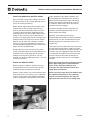
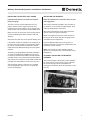
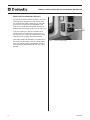
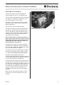
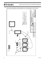
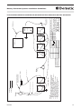
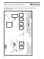
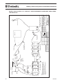
ENGLISH
BATTERY-POWERED SYSTEMS FOR DOMETIC
AUXILIARY AIR CONDITIONING SYSTEMS
INSTALLATION GUIDELINES
Dometic Corporation, Environmental Division
Rev. 20091009
L-2597
WARNING:
Only trained technicians should perform these checks and tests. These units contain voltage
of 12VDC, 24VDC, 115VAC and/or 230VAC. Some of these voltages can be lethal. These units
also contain refrigerant under high pressure. Refrigerant circuits should only be accessed by
licensed technicians.
COPYRIGHT © 2009 Dometic Corporation, Environmental Division, All Rights Reserved.
No part of this publication may be reproduced, translated, stored in a retrieval system, or transmitted in any form or by any means electronic, mechanical,
photocopying, recording or otherwise without prior written consent by Dometic Corporation, Environmental Division. Every precaution has been taken in
the preparation of this manual to ensure its accuracy. However, Dometic Corporation, Environmental Division assumes no responsibility for errors and
omission. Neither is any liability assumed for damages resulting from the use of this product and information contained herein.
2
ENGLISH
Battery-Powered Systems Installation Guidelines
CONTENTS
NOTES AND WARNINGS
4
UNDERSTANDING LOW VOLTAGE DISCONNECTS (LVD)
4
INSTALLING THE BATTERIES
5
INSTALLING ADDITIONAL BATTERY BOXES
6
WIRING THE NEW BATTERIES
6
INSTALLING THE BATTERY FUEL GAUGE
7
INSTALLING THE INVERTER
7
OPTIONAL: INSTALLING THE INVERTER/CHARGER
7
INSTALLING THE INVERTER CONTROLS
8
INSTALLING THE ALTERNATOR
9
DASH CHARGE LIGHT (VOLVO)
10 – 11
TESTING THE ALTERNATOR
12
WIRING THE "IGNITION INTERLOCK" ON THE HVAC UNIT
12
WIRING THE 120VAC POWER TO THE HVAC UNIT
12
OPTIONAL: INSTALLING 120VAC OUTLETS INSIDE THE SLEEPER
13
OPTIONAL: INSTALLING SHOREPOWER CONNECTION
13
WIRING DIAGRAMS FOR BATTERY CONNECTION CONFIGURATIONS
ENGLISH
14 – 21
3
Battery-Powered Systems Installation Guidelines
NOTES AND WARNINGS
IMPORTANT
The Dometic battery-powered air conditioning system is an integrated package of
components which have been carefully selected and tested to work together for proper
performance. The system includes:
• Inverter (or optional inverter with built-in charger)
• High-capacity alternator with external regulator
• AGM Group 31 batteries
• Shorepower connection (optional)
• Inside AC power plugs (optional)
• Dometic air conditioning units with digital controls
Do not substitute any other components than those specified by Dometic. Using
non-standard components may not provide the performance specified by Dometic and
may void your warranty for the air conditioning system.
BEFORE YOU START
•Realize that all the manuals are written to inform an installer that is skilled in mechanical areas, such as
alternators, batteries, and cabling, as well as skilled in HVAC and electrical areas. If you have any questions
after reading this and all manuals that accompany the individual parts, please call 804-746-1313, and
ask for the Dometic Truck Applications Department.
•Open all boxes and check conditions of parts. If parts are damaged, please file the appropriate forms with
the shipping company. If parts are missing, please contact Dometic.
• Refer to Technology and Maintenance Council (TMC) RP160 for guidelines on inverter wiring.
• Realize that all parts required may not necessarily be included, such as:
• Battery cables
• Cable secondary protection (wire loom)
• Some fasteners (i.e., wire ties)
•All tools (i.e., frame drill, bits, wrenches, drills, hole saws)
(Note that it is highly recommended that the called-out tools be used when called for)
• General shop supplies
GETTING THE MATERIALS TOGETHER
• Open all boxes and lay out materials in areas with parts that will be used for the same type of system.
TOOLS THAT MAY BE REQUIRED
• See each individual manual for a list of the tools required.
UNDERSTANDING LOW VOLTAGE DISCONNECTS (LVD)
There are two different LVDs we are going to discuss: the one that is integral to the truck, and the one that
is integral to the Battery-Based HVAC System. The truck’s LVD shuts down at approximately 12.3 VAC. The
HVAC’s LVD shuts down at approximately 10.5 VDC, which yields an open circuit volt (OCV) of approximately
11.5 VDC. This means that during the normal run process of the HVAC system, truck systems will shut down
before the HVAC will.
4
ENGLISH
Battery-Powered Systems Installation Guidelines
INSTALLING THE BATTERIES
You will replace the standard lead-acid batteries with
absorbed glass mat (AGM) batteries (Fig. 1) and also
add extra AGM batteries to get extended time running
on battery power.
The first step is to find space for the extra batteries
and inverter. Note that whenever possible the
inverter should be mounted in the same box with the
batteries.
Available space will vary based on the truck
specifications, such as frame length, fuel tank length
and empty tool boxes already on the truck.
Figure 1 – AGM batteries replace standard lead-acid batteries
If additional boxes are included in your kit, you will
need to mount them firmly to the frame of the truck.
This may require that some slight adjustments be
made to fuel tank placement. Be creative, however,
always be cautious, as any changes you make could
cause problems elsewhere.
If you choose to use boxes already installed on the
truck for additional batteries make sure they are rated
for the weight of the batteries and inverter.
Never disregard OEM suggestions relating to frame
welding and drilling, as they are very important.
Consider center-mount battery boxes (Fig. 2).
Freightliner and Volvo offer center-mount boxes that
offer four battery spaces.
Figure 2 – Center-mount battery box
Dometic offers a range of battery boxes that will
mount on the side of the frame well and a center
mount box, which mounts between the rails, just
behind the cab. Refer to Dometic Publication L–2328
for more information.
These boxes are typically offered pre-loaded with
components. However, the boxes can also be
purchased empty.
ENGLISH
5
Battery-Powered Systems Installation Guidelines
INSTALLING ADDITIONAL BATTERY BOXES
Boxes should be mounted with cabling in mind. The
shorter the cables the less voltage drop and the less
chance for chafing and rubbing.
Mount Dometic battery boxes with four bolts, either
supplied with the box, or Grade 8 fasteners of at
least 5/8" diameter. Some battery boxes come with
a clamp-on mounting solution. Depending on the
mounting location, you may be able to utilize all four
clamps, or you may have to use a combination of
clamp-on vs. through bolting. The final strength of the
bolting solution on the frame rests with the installer.
Washers on both sides with a locking nut (ny-lock,
tri-lobe or stover) are suggested. Lock washers are
not recommended. Torque 5/8" bolts to 140-155 ft-lbs.
Torque 3/4" bolts to 260-280 ft-lbs.
Drill the frame for at least four bolts in the vertical
section (web). Most OEMs do not allow drilling in the
horizontal sections. Most OEMs also do not allow
welding or torching frames. Please be sure that
whatever you do meets OEM requirements, so as not
to void any warranties.
weight, complexity and number of batteries. Use
the wiring diagrams at the back of the manual for
different wiring configurations (Fig. 3).Conductors
between each battery should be of the same size
as conductors between each bank. We normally
recommend at least 2/0 gauge.
Conductors should be as short as possible and
should be routed and clipped securely so as to
prevent chafing and rubbing.
Secondary chafe protection (wire loom) is
recommended on AT LEAST the positive conductors
between banks. It is also recommended that chafe
protection be placed in chafe-prone areas on the
negative wire.
If you make your own cables, either crimp the end on
the cable with the correct tool or solder it on. There
are cable ends available with the solder already in the
end. Either way, it is suggested that the connection
be covered with heavy-duty heat shrink. This helps
to prevent corrosives from being wicked up into
the copper strands, where they can cause hidden
corrosion.
Before installing any batteries, load test each one.
One bad battery can ruin the entire bank. And yes,
sometimes brand new batteries can be bad.
Before and during connection of battery terminals,
apply a light coating of the supplied dielectric
grease (in the small clear packet) to every
connection. This will help keep corrosion and
voltage drop to a minimum.
Batteries can be wired in one of two methods: A dualbank system (house and starting), and a single-bank
system. The dual-bank system provides redundancy,
while the single-bank system provides for less total
Replace the hex or wing nuts on the batteries with
the supplied locking hex nuts. These will help
keep the connections tight over the long haul.
Tight connections will ensure less voltage drop.
WIRING THE NEW BATTERIES
Figure 3 – Batteries connected
6
ENGLISH
Battery-Powered Systems Installation Guidelines
INSTALLING THE BATTERY FUEL GAUGE
INSTALLING THE INVERTER
Follow the manufacturer’s instructions to install the
battery fuel gauge.
Follow the manufacturer’s instructions. Here are some
other suggestions:
The shunt must be connected between the last
battery and the inverter negative post. You may
install the shunt at the battery or at the inverter. The
aluminum bar may be moved to accommodate either.
The inverter should be installed in the same box as
the batteries, so as to keep the cable lengths short,
reducing voltage drop to a minimum.
Make sure that you attach the shunt with the polarity
correct by following the labels marked “Load” and
“Battery.”
Attach the small red wires to the positive battery post.
If the cables need to be extended, use conductors of
the same size. Connections that are outside should
be at least butt-connected and covered in outsiderated shrink tube. Waterproof plugs are also a good
method.
The battery fuel gauge display should be mounted in
an easily accessible place, probably the same area
in which you will mount the HVAC or inverter controls.
Consider first the area at the head of the bed (driver’s
side of the truck). Usually the truck’s HVAC controls are
mounted here and provide a wire chase for your use.
The fuel gauge requires a hole size of a standard
round truck gauge. A hole saw of 2 1/8” gives the
correct mounting hole.
Mount the inverter directly to the metal of the box,
with no material or spacer in between.
Make sure to ground the chassis of the inverter to
the chassis of the truck. Note that 12-gauge wire is
acceptable for this requirement.
Install the Dometic 200 amp circuit breaker or a
properly-sized fuse in the positive cable between the
last battery and the inverter.
Note: If the inverter is to be installed anywhere
other than in the battery box, consult Dometic Truck
Engineering.
OPTIONAL: INSTALLING THE INVERTER/
CHARGER
The inverter/charger and controls will be installed in
the same manner as the inverter (Fig. 4). However,
the inverter/charger will be connected to the
shorepower connection (to be discussed later in this
manual).
Figure 4 – Inverter/Charger installed
ENGLISH
7
Battery-Powered Systems Installation Guidelines
INSTALLING THE INVERTER CONTROLS
The inverter controls should be mounted in an easily
accessible place, probably the same area in which
you will mount the HVAC controls (Fig. 5). Consider
first the area at the head of the bed (driver’s side
of the truck). Usually the truck’s HVAC controls are
mounted here and provide a wire chase for your use.
Inverter control
If you are installing in a day cab, and the inverter
controls consist of a switch that measures 3/4" x 1
1/2", then you can remove the switch from the panel
and install it into an empty dash switch location.
If the cables need to be extended, use conductors of
the same size. Connections that are outside should
be at least butt-connected and covered in outsiderated shrink tube. Waterproof plugs are also a good
method.
8
Figure 5 – Inverter control installed
ENGLISH
Battery-Powered Systems Installation Guidelines
INSTALLING THE ALTERNATOR
Follow the instruction manual included with the
alternator/regulator. Here are a few additional tips.
The new alternator should directly replace the existing
one (Fig. 6) (i.e., pad mount or J180 mount). If not,
you need to request the correct model.
The alternator amp rating is based on the number
of batteries in your system and may be different on
different applications.
You will have to reuse the alternator pulley.
The alternator cabling will have to be upgraded to a
2/0 cable for a 270-amp alternator (typically a day
cab) or a 3/0 cable for a 320-amp alternator (most
sleepers). Run this cable from the positive alternator
stud to the positive starter stud. (See page 20 for
instructions on FTL Cascadia.)
Figure 6 – Alternator installed
Note: On Volvo trucks, you will have to add a 3/0
cable from the truck-side of the negative fuse (see
Battery-Volvo diagram on page 21) to the chassis
stud located just to the inside of the frame rail
behind the driver's side from tire.
Alternator power wiring may have to be upsized or
paralleled with an additional cable if the OEM cable
size is not able to conduct the required current. Refer
to the alternator literature for guidance.
The negative cable must be attached to the negative
terminal on the alternator and the negative terminal
on a battery. It must not go just to chassis ground.
Secondary chafe protection (wire loom) is
recommended on AT LEAST the positive conductor. It
is also recommended that chafe protection be placed
in chafe-prone areas on the negative wire.
If you make your own cables, either crimp the end on
the cable with the correct tool or solder it on. There
are cable ends available with the solder already in the
end. Either way, it is suggested that the connection
be covered with heavy-duty heat shrink. This helps
to prevent corrosives from being wicked up into
the copper strands where they can cause hidden
corrosion.
Make sure that all connections are tight, as loose
connections can cause the regulator not to work
correctly.
ENGLISH
9
Battery-Powered Systems Installation Guidelines
DASH CHARGE LIGHT
Note for all Volvo Trucks: If your existing alternator
has an "I" terminal with wire attached, you may
need to add a relay to make the “Alternator” or
“Charge” dash light work correctly. One way to tell
is if the existing alternator has a wire hooked to the
"I" terminal. If the new alternator does not have this
terminal, then you will need the charge light relay.
If you do not already have the charge light relay,
request Dometic P/N 4163717. This wire will later be
used to connect to the charge light relay. See drawing
“Charge Light Circuit for Alternators” below. The
relay required is a small flange-mount 12VAC relay,
like Song Chaun #792H, Tyco #V23234A0001X036,
Bosch #0 332 209 150, Dometic P/N 4135000 or P/N
4135010.
10
ENGLISH
REV.
-
DATE
Wire Labeled
"Ground"
Wire Labeled
"Stator"
Back of
Alternator
DC
Negative
30
REVISIONS
DESCRIPTION
+
85
DC
Positive
MADE BY
87
APPR BY
86
Relay Terminal No.
30
85
86
87
Connection Point
Charge Lite Wire
Stator Tap
Ground (-12vdc)
Positive (+12vdc)
DOCID
Sheet
1:2
02/25/09
SCALE:
DATE:
SIZE:
A
VENDOR
NO.
APR BY:
DWG BY:
1 of 1
KEA
080418
PART NUMBER:
SW
Cruisair
O.I.
Volvo Charge Lite Relay Hook-up
See also 4163717
Dometic Corporation
PROPRIETARY NOTE: THE INFORMATION CONTAINED WITHIN THIS DOCUMENT IS THE PROPERTY OF
DOMETIC CORPORATION. ANY ATTEMPT TO COPY OR DISTRIBUTE WITHOUT WRITTEN CONSENT FROM
DOMETIC CORPORATION SHALL BE CONSIDERED UNLAWFUL AND CAN BE CONTESTED IN A COURT OF LAW.
To Charge Lite Relay
Wire Labeled
"12VDC"
Wire Labeled
"Charge Lite Wire"
To Charge Lite Wire
(removed from old
Alternator's "I" Terminal)
DWG
ENGLISH
REV
Stator Terminals
Stator Terminals
Stator Terminals
Battery-Powered Systems Installation Guidelines
CHARGE LIGHT CIRCUIT FOR ALTERNATORS WITH INTEGRAL (Built-In) REGULATORS
11
Battery-Powered Systems Installation Guidelines
TESTING THE ALTERNATOR
Alternator voltage test. Connect the test leads of
a volt meter to the alternator output terminals. Note:
Most Leece Neville alternators have isolated
ground rectification. Always connect tester/volt
meter directly to the negative output terminal of
the alternator or your test will be inaccurate.
• Start engine, increase to high idle (1500
RPM): The volt meter should now indicate that
the alternator output voltage has increased to
a range from 13.8 volts to 14.2 volts. (Ensure
that all electrical accessories of the vehicle are
in the off position.) If voltage increases but is
out of range, inspect to see if the alternator has
an adjustable regulator. If so, reduce engine
speed to idle and adjust voltage to a setting of
14.0 volts. If voltage is higher than 14.7 volts
and cannot be adjusted below 14.25 volts, or if
voltage is lower than 13.8 volts and cannot be
adjusted into range, then replace the alternator.
For more information, please reference LeeceNeville Technical Publication, TSB-1019.
WIRING THE 120VAC POWER TO THE HVAC
UNIT
Follow the directions and wiring diagrams in your air
conditioner installation manual.
The connection of the 120VAC cable to the inverter
should be done with either the extension cable
or the Y-cable assembly. Dielectric grease should
be applied to any connections outside of the cab
structure. “Splicing” outside of the cab without taking
precautions for waterproofing is not permissible and
may void your warranty.
Only as many extensions as required should be used.
Cables should be routed and clipped securely so as
to prevent chafing and rubbing.
The connection at the HVAC unit should be done with
the supplied plug.
WIRING THE "IGNITION INTERLOCK" ON THE
HVAC UNIT
• If your HVAC is provided with an “Ignition
Interlock” cable, then follow these steps to
properly connect it.
1. C
onnect the white wire from the “Ignition
Interlock” cable to the “ON" position of the
key switch. Here are some suggestions:
12
• Volvo - in the sleeper control panel
cabling - wire F60A1-08
• FTL Cascadia - wire under passenger
dash to connector X-6 of the SAM-Cab,
pin #10
• International Prostar - pink wire labeled
"A13EE" in the driver's side luggage
box.
2. Connect the black wire from the “Ignition
Interlock” cable to grounded, metal chassis
connection.
•S
tart the HVAC unit. Turn the key to the “ACC”
position. If the HVAC turns off when the ignition
is in the “ACC” position, you need to revise your
connection. Use a voltmeter to ensure that your
connection point allows for power ONLY when
the keyswitch is in the 'ON' position.
ENGLISH
Battery-Powered Systems Installation Guidelines
OPTIONAL: INSTALLING 120VAC OUTLETS
INSIDE THE SLEEPER
If so equipped, the system will have 120VAC outlets
that can be installed inside the sleeper for accessory
use. The outlets may be installed anywhere inside
the sleeper, however, they should be installed in an
area that makes sense for the loads the driver will be
applying (i.e., probably near one cabinet or the other).
The outlets should be installed with the Y-cable
connection to the main cable between the inverter
and the HVAC unit.
OPTIONAL: INSTALLING SHOREPOWER
CONNECTION
Figure 8 – Shorepower connection installed
The shorepower connection is only available with the
inverter/charger.
The shorepower connection should be installed
preferably on the driver’s side of the truck. If the
driver’s side of the truck is not in reach of the battery
box in which the inverter/charger is mounted, then
the connection should be installed as close to the
inverter/charger as possible (Fig. 8). This will probably
be in the side of the battery box in which the inverter/
charger is mounted.
ENGLISH
13
14
Alternator
-
+
-
Battery 1
+
AC Wiring
DC Wiring
+
Battery 2
-
Factory Negative alternator lead
Factory Positive alternator lead
Add a 2/0 cable from positive
alternator stud to positive starter
stud. 3/8" ring terminal for the
alternator, 1/2" for the starter.
+
+
Battery 3
Starter
-
THE INFORMATION CONTAINED IN THIS
DRAWING IS THE SOLE PROPERTY OF
DOMETIC CORP. ANY
REPRODUCTION IN PART OR AS A WHOLE
WITHOUT THE WRITTEN PERMISSION OF
DOMETIC COR IS PROHIBITED.
-
APPLICATION
NEXT ASSY
Overcurrent
Protector
+
PROPRIETARY AND CONFIDENTIAL
Factory starter
cable
Inverter
120VAC Line
USED ON
DO NOT SCALE DRAWING
FINISH
MATERIAL
INTERPRET GEOMETRIC
TOLERANCING PER:
DIMENSIONS ARE IN INCHES
TOLERANCES:
FRACTIONAL
ANGULAR: MACH
BEND
TWO PLACE DECIMAL
THREE PLACE DECIMAL
COMMENTS:
Q.A.
MFG APPR.
ENG APPR.
CHECKED
DRAWN
UNLESS OTHERWISE SPECIFIED:
DATE
9/29/08
NAME
KEA
SCALE: 1:1 WEIGHT:
B Battery1
SIZE DWG. NO.
SHEET 1 OF 1
B
REV
Day Cab system -HVAC System
Powered by Inverter and
Multiple Starting/
Deep Cycle Batteries
TITLE:
Dometic Environmental
NOTES:
1) Batteries must be of the AGM dual purpose deep cycle/
startingtype
2) Alternator must be upgraded. Discuss with Dometic
Applications Department for recommendation.
3) Inverter must be of approved type by Dometic in order
to insure proper operation of system.
4) Cable size should be choosen based on voltage drop
and load.
HVAC Unit
Battery-Powered Systems Installation Guidelines
HVAC SYSTEM POWERED BY INVERTER AND MULTIPLE STARTING/DEEP CYCLE BATTERIES
ENGLISH
ENGLISH
+
+
Primary (OEM) Box
-
-
+
Start
Battery 2
Start
Battery 1
Factory Positive Alternator Cable
Factory Negative Alternator Cable
+
Battery
Separator
Factory Starter Cable
Starter
Add at least a 3/0 cable from the
alternator positive to the starter
positive lug. 3/8" ring terminal on
the alternator, 1/2" at the starter.
NOTES:
1) House Batteries must be of the AGM deep cycle type
2) Alternator shall be upgraded. Discuss with Dometic
Applications Department for recommendation.
3) Inverter must be of approved type by Dometic in order
to insure proper operation of system.
4) All added DC cables shall be of 2/0 size or larger,
unless otherwise noted on drawing.
5) Either bank may have as many or few batteries
in order to provide the desired run time.
-
Alternator
AC Wiring
DC Wiring
PROPRIETARY AND CONFIDENTIAL
THE INFORMATION CONTAINED IN THIS
DRAWING IS THE SOLE PROPERTY OF
DOMETIC CORP. ANY
REPRODUCTION IN PART OR AS A WHOLE
WITHOUT THE WRITTEN PERMISSION OF
DOMETIC CORP IS PROHIBITED.
+
APPLICATION
NEXT ASSY
-
House
Battery 1
USED ON
-
Secondary Box
-
House
Battery 3
DO NOT SCALE DRAWING
FINISH
MATERIAL
INTERPRET GEOMETRIC
TOLERANCING PER:
DIMENSIONS ARE IN INCHES
TOLERANCES:
FRACTIONAL
ANGULAR: MACH
BEND
TWO PLACE DECIMAL
THREE PLACE DECIMAL
COMMENTS:
Q.A.
MFG APPR.
ENG APPR.
CHECKED
DRAWN
UNLESS OTHERWISE SPECIFIED:
+
House
Battery 2
HVAC Unit
+
DATE
9/29/08
NAME
KEA
-
+
Overcurrent
Protection
SCALE: 1:1 WEIGHT:
B Battery2
SIZE DWG. NO.
SHEET 1 OF 1
E
REV
HVAC System Powered by
Inverter and Separate Battery
Banks with Batt. Separator
TITLE:
Dometic Environmental
House
Battery 4
-
Inverter
+
120VAC Line
Battery-Powered Systems Installation Guidelines
HVAC SYSTEM POWERED BY INVERTER AND SEPARATE BATTERY BANKS WITH BATTERY SEPARATOR
15
16
-
Start
Battery 1
+
Factory Positive
alternator cable
Factory Negative
alternator cable
-
Start
Battery 2
+
Factory Starter
Cable
Starter
Add at least a 3/0 cable from the
alternator positive to the starter positive
lug. 3/8" ring terminal at the alternator,
1/2" at the starter.
NOTES:
1) House Batteries must be of the AGM deep cycle type
2) Alternator must be upgraded. Discuss with Dometic
Applications Department for recommendation.
3) Inverter must be of approved type by Dometic in order
to insure proper operation of system.
4) All added cables shall be of 2/0 or larger, unless
otherwise specified on the drawing.
5) Either bank may have as many or few batteries in
order to provide the desired run time.
Alternator
AC Wiring
DC Wiring
THE INFORMATION CONTAINED IN THIS
DRAWING IS THE SOLE PROPERTY OF
DOMETIC CORP. ANY
REPRODUCTION IN PART OR AS A WHOLE
WITHOUT THE WRITTEN PERMISSION OF
DOMETIC CORP. IS PROHIBITED.
PROPRIETARY AND CONFIDENTIAL
Battery
Separator
HVAC Unit
APPLICATION
NEXT ASSY
USED ON
-
House
Battery 1
-
+
DO NOT SCALE DRAWING
FINISH
MATERIAL
INTERPRET GEOMETRIC
TOLERANCING PER:
DIMENSIONS ARE IN INCHES
TOLERANCES:
FRACTIONAL
ANGULAR: MACH
BEND
TWO PLACE DECIMAL
THREE PLACE DECIMAL
COMMENTS:
Q.A.
MFG APPR.
ENG APPR.
CHECKED
DRAWN
UNLESS OTHERWISE SPECIFIED:
+
House
Battery 2
Inverter with Shorepower Pass-Thru
Capability OR Inverter/charger
Cab Power
Outlets
DATE
9/29/08
NAME
KEA
-
House
Battery 3
-
+
Overcurrent
Protection
House
Battery 4
+
120VAC Line
Dometic Environmental
SCALE: 1:1 WEIGHT:
E
REV
SHEET 1 OF 1
B Battery 3
SIZE DWG. NO.
HVAC System Powered by
Inverter and Separate Battery
Banks with Separator. Shore
power and cab power outlets
TITLE:
+
-
Y-Cord
Splitter
Shorepower
Inlet
Battery-Powered Systems Installation Guidelines
HVAC SYSTEM POWERED BY INVERTER AND SEPARATE BATTERY BANKS WITH SEPARATOR SHOREPOWER AND CAB POWER OUTLETS
ENGLISH
ENGLISH
-
Start
Battery 1
-
Start
Battery 2
+
Primary (OEM) Box
+
Factory Positive alternator cable
Factory Negative alternator cable
Factory Starter
Cable
Starter
Add at least a 3/0 cable from the
alternator positive to the starter positive
lug. 3/8" ring terminal at the alternator,
1/2" at the starter.
NOTES:
1) House Batteries must be of the AGM deep cycle type
2) Alternator must be upgraded. Discuss with Dometic
Applications Department for recommendation.
3) Inverter must be of approved type by Dometic in order
to insure proper operation of system.
4) All added DC cables shall be 2/0 or larger unless
otherwise noted on the drawing.
5) Either bank may have as many or few batteries in
order to provide the desired run time.
Alternator
AC Wiring
DC Wiring
THE INFORMATION CONTAINED IN THIS
DRAWING IS THE SOLE PROPERTY OF
DOMETIC CORPORATION. ANY
REPRODUCTION IN PART OR AS A WHOLE
WITHOUT THE WRITTEN PERMISSION OF
DOMETIC CORP IS PROHIBITED.
PROPRIETARY AND CONFIDENTIAL
Battery
Separator
APPLICATION
NEXT ASSY
USED ON
-
House
Battery 1
+
DO NOT SCALE DRAWING
FINISH
MATERIAL
INTERPRET GEOMETRIC
TOLERANCING PER:
DIMENSIONS ARE IN INCHES
TOLERANCES:
FRACTIONAL
ANGULAR: MACH
BEND
TWO PLACE DECIMAL
THREE PLACE DECIMAL
COMMENTS:
Q.A.
MFG APPR.
ENG APPR.
CHECKED
DRAWN
UNLESS OTHERWISE SPECIFIED:
+
House
Battery 2
+
NAME
KEA
DATE
9/29/08
-
+
Overcurrent
Protection
House
Battery 4
+
SCALE: 1:1 WEIGHT:
B
REV
SHEET 1 OF 1
B Battery 4
SIZE DWG. NO.
HVAC System Powered by
Inverter and Separate Battery
Banks with Separator.
Shorepower capability
TITLE:
Dometic Environmental
-
120VAC Line
Secondary Box
-
House
Battery 3
Inverter with Shorepower Pass-Thru
Capability OR Inverter/charger
HVAC Unit
Shorepower Inlet
Battery-Powered Systems Installation Guidelines
HVAC SYSTEM POWERED BY INVERTER AND SEPARATE BATTERY BANKS WITH SEPARATOR SHOREPOWER CAPABILITY
17
18
+
-
Battery 1
+
Factory Positive Alternator
Cable
-
+
Factory Starter
Cable
Battery 2
+
Primary (OEM) Box
Factory Negative Alternator
Cable
-
-
Battery 3
+
-
-
THE INFORMATION CONTAINED IN THIS
DRAWING IS THE SOLE PROPERTY OF
DOMETIC CORPORATION. ANY
REPRODUCTION IN PART OR AS A WHOLE
WITHOUT THE WRITTEN PERMISSION OF
DOMETIC CORP IS PROHIBITED.
PROPRIETARY AND CONFIDENTIAL
+
Battery 5
120VAC Line
Battery 4
Cab Power
Outlet
Starter
Add at least a 3/0 cable from the
alternator positive to the starter
posiive lug. 3/8" ring terminal at the
alternator, 1/2" at the starter.
NOTES:
1) ALLBatteries must be of the AGM deep cycle type
2) Alternator must be upgraded. Discuss with Dometic
Applications Department for recommendation.
3) Inverter must be of approved type by Dometic in order
to insure proper operation of system.
4) All added DC cables shall be of 2/0 size or larger, unless
otherwise noted on drawing.
5) Battery bank size may have as many or few batteries
in order to provide the desired run time.
Alternator
AC Wiring
DC Wiring
-
APPLICATION
NEXT ASSY
+
DO NOT SCALE DRAWING
FINISH
MATERIAL
INTERPRET GEOMETRIC
TOLERANCING PER:
DIMENSIONS ARE IN INCHES
TOLERANCES:
FRACTIONAL
ANGULAR: MACH
BEND
TWO PLACE DECIMAL
THREE PLACE DECIMAL
COMMENTS:
Q.A.
MFG APPR.
ENG APPR.
CHECKED
DRAWN
UNLESS OTHERWISE SPECIFIED:
Overcurrent
Protection
USED ON
Secondary Box
+
Battery 6
Y-Cord Splitter
to GFCI Receptacle
HVAC Unit
+
DATE
9/29/08
NAME
KEA
SCALE: 1:1 WEIGHT:
B
REV
SHEET 1 OF 1
B Battery 5
SIZE DWG. NO.
HVAC System Powered by
Inverter. Single starting/house
Battery Bank. Shore
power with cab power outlets
TITLE:
Dometic Environmental
Inverter with Shorepower Pass-Thru
Capability OR Inverter/charger
-
Shorepower Inlet
Battery-Powered Systems Installation Guidelines
HVAC SYSTEM POWERED BY INVERTER - SINGLE STARTING/HOUSE BATTERY BANK SHOREPOWER WITH CAB POWER OUTLETS
ENGLISH
ENGLISH
-
Battery 1
+
Factory Positive alternator
Cable
Factory Negative alternator
Cable
-
+
-
+
-
Battery 3
+
-
+
-
THE INFORMATION CONTAINED IN THIS
DRAWING IS THE SOLE PROPERTY OF
DOMETIC CORPORATION. ANY
REPRODUCTION IN PART OR AS A WHOLE
WITHOUT THE WRITTEN PERMISSION OF
DOMETIC CORP IS PROHIBITED.
-
APPLICATION
NEXT ASSY
USED ON
Secondary Box
+
Battery 6
120VAC Line
Battery 5
PROPRIETARY AND CONFIDENTIAL
Battery 4
Starter
Factory Starter Cable
Primary (OEM) Box
Battery 2
+
Add at least a 3/0 size cable from the
alternator positive to the starter positive
lug. 3/8" ring terminal at the alternator,
1/2" at the starter.
NOTES:
1) ALLBatteries must be of the AGM deep cycle type
2) Alternator must be upgraded. Discuss with Dometic
Applications Department for recommendation.
3) Inverter must be of approved type by Dometic in order
to insure proper operation of system.
4) All added DC cables shall be of 2/0 size or larger, unless
otherwise noted on the drawing.
5) Battery bank may be as many or few batteries
in order to provide the desired run time.
Alternator
AC Wiring
DC Wiring
DO NOT SCALE DRAWING
FINISH
MATERIAL
INTERPRET GEOMETRIC
TOLERANCING PER:
DIMENSIONS ARE IN INCHES
TOLERANCES:
FRACTIONAL
ANGULAR: MACH
BEND
TWO PLACE DECIMAL
THREE PLACE DECIMAL
COMMENTS:
Q.A.
MFG APPR.
ENG APPR.
CHECKED
DRAWN
UNLESS OTHERWISE SPECIFIED:
Overcurrent
Protection
+
HVAC Unit
+
DATE
9/29/08
NAME
KEA
SCALE: 1:1 WEIGHT:
B
REV
SHEET 1 OF 1
B Battery 6
SIZE DWG. NO.
HVAC System Powered by
Inverter. Single starting/house
Battery Bank. Shore
power capability.
TITLE:
Dometic Environmental
Inverter with Shorpower passthrough OR inverter/cherger
-
Shorepower Inlet
Battery-Powered Systems Installation Guidelines
HVAC SYSTEM POWERED BY INVERTER - SINGLE STARTING/HOUSE BATTERY BANK SHOREPOWER CAPABILITY
19
20
-
-
-
Battery 3
+
OEM
Battery
Disconnect
Switch
OEM Fuse
Block
+
+
+
NOTES:
1) House Batteries must be of the AGM deep cycle type
2) Alternator shall be upgraded. Discuss with Dometic
Applications Department for recommendation.
3) Inverter must be of approved type by Dometic in order
to insure proper operation of system.
4) Cable size is choosen based on voltage drop and
load. All cables shall be 2/0 unless otherwise noted
on drawing.
-
Battery 4
Primary (OEM) BOX
Battery 2
+
-
AC Wiring
DC Wiring
Battery 1
+
Alternator
+
-
Battery 5
Starter
.
2/0 Connector
Cables
Add at least
a 3/0 positive
cable fromthe
alternator to the
positive starter
stud. 3/8" post at
alterntor, 1/2" post
at starter.
Remove
factory
wires from
alternator.
Splice together,
insulate, and tie
up out of the way
To intake
grid heater
PROPRIETARY AND CONFIDENTIAL
+
APPLICATION
NEXT ASSY
-
Battery 8
SECONDARY BOX
-
THE INFORMATION CONTAINED IN THIS
DRAWING IS THE SOLE PROPERTY OF
<INSERT COMPANY NAME HERE>. ANY
REPRODUCTION IN PART OR AS A WHOLE
WITHOUT THE WRITTEN PERMISSION OF
<INSERT COMPANY NAME HERE> IS
PROHIBITED.
-
+
Battery 7
+
Battery 6
Y-Cord Splitter
to GFCI Receptacle
Cab Power
Outlet
120VAC Line
USED ON
DO NOT SCALE DRAWING
FINISH
MATERIAL
INTERPRET GEOMETRIC
TOLERANCING PER:
DIMENSIONS ARE IN INCHES
TOLERANCES:
FRACTIONAL
ANGULAR: MACH
BEND
TWO PLACE DECIMAL
THREE PLACE DECIMAL
COMMENTS:
Q.A.
MFG APPR.
ENG APPR.
CHECKED
DRAWN
UNLESS OTHERWISE SPECIFIED:
Overcurrent
Protection
HVAC Unit
+
DATE
9/29/08
NAME
KEA
SCALE: 1:1 WEIGHT:
B
REV
SHEET 1 OF 1
B Battery 7
SIZE DWG. NO.
Dometic HVAC System to FTL
Cascadia. Inverter/charger,
shorepower, and alternator.
TITLE:
Dometic Environmental
Inverter with Shorepower Pass-Thru
Capability OR Inverter/charger
-
Shorepower Inlet
Battery-Powered Systems Installation Guidelines
DOMETIC HVAC SYSTEM TO FTL CASCADIA – INVERTER/CHARGER, SHOREPOWER, AND ALTERNATOR REGULATOR
ENGLISH
ENGLISH
Left Front Tire
Factory Positive
B
New Positive
3/0 cable to
Starter Positive
Engine
Block
Factory Positive
Starter
Field Wiring
NOTES:
1) Batteries must be of the AGM deep cycle type
2) Added cables must be 2/0 or larger.
3) Add a positive cable from positive on the alternator
to the positive post on the starter.
4) Add a negative cable from the Frame Ground Post
to the Truck side of the Negative
Fuse (not the battery
side.)
5) Drawing does NOT apply to Volvo trucks manufactured
between 1996 and end of 2006.
6) 400 amp Fuse in Negative cable changed to fusible link in
2008, week 46.
7) Alternator and/or starter location may change depending
on the type of engine installed.
Factory Wiring
Frame Ground
Post
Engine Ground
Post
Factory Negative
Alternator
Right Front Tire
A
A
B
B
-
THE INFORMATION CONTAINED IN THIS
DRAWING IS THE SOLE PROPERTY OF
DOMETIC CORP. ANY
REPRODUCTION IN PART OR AS A WHOLE
WITHOUT THE WRITTEN PERMISSION OF
DOMETIC COR IS PROHIBITED.
A
-
+
APPLICATION
NEXT ASSY
-
+
Positive Fuse
USED ON
Negative Fuse (or fusible link)
PROPRIETARY AND CONFIDENTIAL
+
-
+
Added 3/0
Negative cable
Factory Negative
Revisions
DO NOT SCALE DRAWING
FINISH
MATERIAL
INTERPRET GEOMETRIC
TOLERANCING PER:
DIMENSIONS ARE IN INCHES
TOLERANCES:
FRACTIONAL
ANGULAR: MACH
BEND
TWO PLACE DECIMAL
THREE PLACE DECIMAL
COMMENTS:
Q.A.
MFG APPR.
ENG APPR.
CHECKED
DRAWN
UNLESS OTHERWISE SPECIFIED:
DATE
10/2/08
NAME
KEA
KEA
KEA
APPROVED
SCALE: 1:1 WEIGHT:
REV
B
SHEET 1 OF 1
B Battery-Volvo
SIZE DWG. NO.
Field added DC cabling for Volvo
Trucks YM post 2006:
Change to upgraded alternator
for Dometic Battery Powered
HVAC System
TITLE:
Dometic Environmental
8/25/2009
Chg Alternator Cabling to 3/0. Add note about YM
2009 and later trucks.
B
DATE
4/21/2009
Change Title to include only Volvo Trucks built post2006. Add notes pertaining to this change.
DESCRIPTION
A
REV.
Battery Box
Left Frame Rail
NOTE: Volvo has several variations of this cabling. The most recent change is that
the ground post on the frame is located behind the battery box. In this can, route
a new negative cable from the ground on the alternator to this stud. See also Note
6 below.
Right Frame Rail
Battery-Powered Systems Installation Guidelines
FIELD-ADDED DC CABLING FOR VOLVO: CHANGE TO UPGRADED ALTERNATOR FOR DOMETIC
BATTERY-POWERED HVAC SYSTEM
21
NOTES:
22
ENGLISH
NOTES:
ENGLISH
23
Dometic Corporation, Environmental Division
P.O. Box 15299 I Richmond, VA 23227 USA I 804-746-1313 I Fax 804-746-7248
www.dometictruck.com I [email protected]
UNITED STATES & CANADA SERVICE ONLY
Weekdays 8:00 am to 5:00 pm (Eastern Time) 804-746-1313
All other times 888-440-4494
L-2597
Rev. 20091009
For all other areas visit our website to find your nearest distributor.