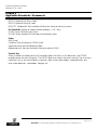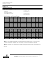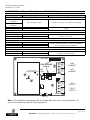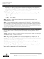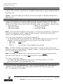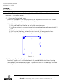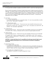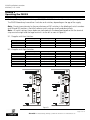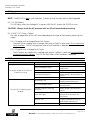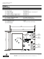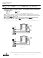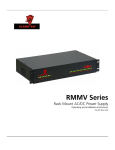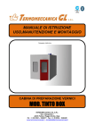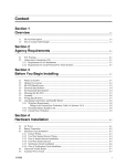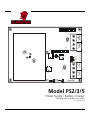
1
AC FUSE F1 AC 1, 2 OPE N = 24 V 3 OPEN = DC FLT DIS ABLE 4 OPEN =AC FLT DISA BLE F2 - BAT FUSE + BATTERY CONNECT LOW VOLTAGE AC CONNECT TB1 A1 R7 REG ADJ W5 D12 REF ADJ R2 1 1 2 3 4 24/12V DC FLT AC FLT S1 TB2 DC OUTPUT + FLT + - BFF ADJ FAULT OUTPUT - R16 PS2 PS3 PS5 PS5-UL AlarmSaf Model PS2/3/5 Power Supply / Battery Charger Operating and Installation Instructions 52-133 Rev B.01 PS2/3/5 Installation Instructions 8/23/2007, 2:51:41 PM I. Warnings and Notices y WARNING - To reduce the risk of fire or electric shock, do not expose this product to rain or moisture y WARNING - This installation and all servicing should be made by qualified service personnel and should conform to all local codes y NOTICE - This equipment shall be installed in a manner which prevents unintentional operation from employees or other personnel working about the premises, by falling objects, by building vibration and by similar causes y NOTICE - This equipment is not intended for use within the patient care areas of a Health Care Facility Symbol Definitions WARNING - Read the instruction manual to avoid personal injury or property damage Ꮨ WARNING - Risk of electric shock. Service to be performed by a qualified service person 52-133 Rev B.01 Page 2 of 16 AlarmSaf 65A Industrial Way, Wilmington, MA 01887 978 658 6717 www.alarmsaf.com PS2/3/5 Installation Instructions 8/23/2007, 2:51:41 PM Table of Contents Section I. Warnings and Notices 1 Introduction Page 2 4 2 Applicable Standards / Documents 5 3 System Overview 3.1 Electrical Ratings and Specifications 3.2 Terminal Descriptions and Electrical Ratings 3.3 AC Input Connection 3.4 Battery Terminals 3.5 DC Output Terminals 3.6 Fault Reporting Terminals 3.7 Fusing 6 6 7 8 8 9 9 9 4 Installation 4.1 Mounting 4.2 Wiring 10 10 11 5 Operating the PS2/3/5 5.1 Setting the DIP Switches 5.2 Visual Indicators 5.3 Troubleshooting 12 12 13 13 6 Specifications 6.1 Electrical Specifications 6.2 Temperature Specifications 6.3 Mechanical Specifications 14 14 14 14 Appendix A Wiring an AlarmSaf RBKS Module to a PS2/3/5 Voltage Fault Output 15 15 52-133 Rev B.01 Page 3 of 16 AlarmSaf 65A Industrial Way, Wilmington, MA 01887 978 658 6717 www.alarmsaf.com PS2/3/5 Installation Instructions 8/23/2007, 2:51:41 PM Section 1 Introduction The PS2/3/5 is a linear power supply designed for use in the access control, fire industry, and related industries by the systems integrator. Features: y Output voltage of 12V or 24VDC y Units can charge up to a maximum 38AH of battery within 48 hours y All units employ full fault detection with an optional Form-C relay output y Fault conditions monitored include: y Low or missing AC y High or low output / battery y Blown fuse y Reversed Battery y Internal Power Supply failure y Visual indicators include: y AC Presence (Green) y System OK or System Trouble (Green or Yellow) 52-133 Rev B.01 Page 4 of 16 AlarmSaf 65A Industrial Way, Wilmington, MA 01887 978 658 6717 www.alarmsaf.com PS2/3/5 Installation Instructions 8/23/2007, 2:51:41 PM Section 2 Applicable Standards / Documents NFPA Standards NFPA 72 National Fire Alarm Code NFPA 70 National Electrical Code NFPA 731 Standard for the Installation of Electronic Premises Security Systems UL Standards (Applies to model numbers ending in “-UL” only) UL 294 Access Control System Units UL 1481 Power Supplies for Fire Protective Signaling System Other MEA Listed California State Fire Marshal (CSFM) Listed Applicable Local and State Building Codes Requirements of the Local Authority Having Jurisdiction (LAHJ) Product Use When installed in accordance with all standards listed in Section 2 of this document, the PS2/3/5 provides power for use with typical 12 or 24VDC devices as used in the access control, fire, or security industries such as, but not limited to, mag locks, door strikes, door holders, smoke dampers, four wire smoke detectors, card readers, keypads, etc. 52-133 Rev B.01 Page 5 of 16 AlarmSaf 65A Industrial Way, Wilmington, MA 01887 978 658 6717 www.alarmsaf.com PS2/3/5 Installation Instructions 8/23/2007, 2:51:41 PM Section 3 System Overview 3.1 Electrical Ratings and Specifications Manufactured By AlarmSaf 65A Industrial Way Wilmington, MA 01887 Tel: 800 987 1050 Tel: 978 658 6717 Fax: 978 658 8638 www.alarmsaf.com Model Numbers and Electrical Ratings PS2-BD PS3-BD PS5-BD PS5-12040-BD PS5-24040-BD PS5-UL-12-BD PS5-UL-24-BD PS5-12025-UL-BD PS5-24025-UL-BD PS5-12040-UL-BD PS5-24040-UL-BD Order Number 00804 00805 00806 00844 00845 01301 01302 01326 01327 01311 01312 Enclosure (Note 2) None None None None None None None None None None None Input Voltage Note 1 Note 1 Note 1 17.5VAC 28.2VAC 17.5VAC 28.2VAC 17.5VAC 28.2VAC 17.5VAC 28.2VAC Max Input Current or TXFMR Rqd. 16V50, T24V4A T12V5A, T24V5A T12V5A, T24V5A T12V5A T24V5A T12V5A T24V5A T12V5A T24V5A T12V5A T24V5A PS3-BFS-12 PS3-BFS-24 PS5-BFS-12 PS5-BFS-24 PS5-12040-B03 PS5-24040-B03 PS5-BFS-12-UL PS5-BFS-24-UL PS5-12025-B03-UL PS5-24025-B03-UL PS5-12040-B03-UL PS5-24040-B03-UL 00809 00810 00811 00812 00834 00836 01303 01304 01317 01318 01313 01314 11x15x4 11x15x4 11x15x4 11x15x4 11x15x4 11x15x4 11x15x4 11x15x4 11x15x4 11x15x4 11x15x4 11x15x4 120VAC 120VAC 120VAC 120VAC 120VAC 120VAC 120VAC 120VAC 120VAC 120VAC 120VAC 120VAC 1.25A 2.50A 1.25A 2.50A 1.25A 2.50A 1.25A 2.50A 1.25A 2.50A 1.25A 2.50A Model 12/24VDC 12/24VDC 12/24VDC 12VDC 24VDC 12VDC 12VDC 12VDC 24VDC 12VDC 24VDC Max Output Current 2A 3A 4A 4A 4A 4A 4A 2.5A 2.5A 4A 4A Max Battery 14AH 20AH 38AH 38AH 38AH 38AH 38AH 38AH 38AH 38AH 38AH Fault Output Type Voltage Voltage Voltage Form-C Form-C Voltage Voltage Form-C Form-C Form-C Form-C 12VDC 24VDC 12VDC 24VDC 12VDC 24VDC 12VDC 24VDC 12VDC 24VDC 12VDC 24VDC 3A 3A 4A 4A 4A 4A 4A 4A 2.5A 2.5A 4A 4A 20AH 20AH 38AH 38AH 38AH 38AH 38AH 38AH 38AH 38AH 38AH 38AH Voltage Voltage Voltage Voltage Form-C Form-C Voltage Voltage Form-C Form-C Form-C Form-C Output Voltage Table 3.1 Note 1: Input Voltage is dependent on the desired output voltage setting. For a 12V output, a 17.5VAC transformer is required. For a 24V output, a 28.2VAC transformer is required. Note 2: Some PS5-12xxx and PS5-24xxx models have optional enclosure sizes not covered in this manual. 52-133 Rev B.01 Page 6 of 16 AlarmSaf 65A Industrial Way, Wilmington, MA 01887 978 658 6717 www.alarmsaf.com PS2/3/5 Installation Instructions 8/23/2007, 2:51:41 PM 3.2 PS2/3/5 Board Terminal Descriptions and Electrical Ratings Terminal / Connector Description TB1 - Low Voltage AC Input and Battery Output LOW VOLT AC CONNECT Low voltage AC input LOW VOLT AC CONNECT BATTERY CONNECT + Positive Battery Connection BATTERY CONNECT Negative Battery Connection Rating 12VDC or 24VDC at 14AH - 38AH - See Table 3.1 for Ratings TB2 - DC Output and Fault Output DC OUTPUT + DC Positive Output DC OUTPUT DC Common Output 12VDC or 24VDC at full output current of supply - See Table 3.1 for ratings. 17.5VAC or 28.2VAC - See Table 3.1 for Ratings Units with Relay Fault Output FAULT OUTPUT NC Fault Relay Output Normally Closed FAULT OUTPUT C Fault Relay Output Common FAULT OUTPUT NO Fault Relay Output Normally Open 1 Amp at 24VDC (Resistive) - Contacts are labeled in the non-powered (Fault) condition Units with Voltage Fault Output FAULT OUTPUT + Low-Current Fault Output + FAULT OUTPUT Low-Current Fault Output - AC FUSE For connection to AlarmSaf RBKS module ONLY - See Section 3.6 and Appendix A BAT CONNECT + - BAT FUSE BAT FUSE 1, 2 OPEN = 24 V 3 O PEN = DC FLT DISABL E 4 O PEN =AC FLT DISABLE F2 RED LED NOT A VISUAL INDICATOR AC LVAC CONNECT BATTERY CONNECT TB1 FUSE RATINGS AGC-10 LOW VOLTAGE AC CONNECT F1 AC FUSE A1 R7 W5 D12 REG ADJ REF ADJ R2 1 1 2 3 4 24/12V DC FLT AC FLT S1 TB2 DC OUTPUT FAULT OUTPUT - DC OUTPUT FAULT OUTPUT + R16 FLT + - BFF ADJ PS2 PS3 PS5 PS5-UL AlarmSaf Figure 3.2 Note: Wire should be sized appropriately for voltage drop and current carrying capability. All terminals are labeled for polarity where appropriate. 52-133 Rev B.01 Page 7 of 16 AlarmSaf 65A Industrial Way, Wilmington, MA 01887 978 658 6717 www.alarmsaf.com PS2/3/5 Installation Instructions 8/23/2007, 2:51:41 PM 3.3 AC Input Connection 3.3.1 Board-Level Supplies Board-level units need to be connected to an appropriate low-voltage AC supply voltage of a sufficient VA rating (See Table 3.1). The connection is made on TB1 at the terminals labeled “Low Voltage AC Connect.” The phase of this connection is not important. 3.3.2 Cabinet-Level Supplies Cabinet-level supplies are pre-fitted with a hardwired transformer of the correct voltage. The connections should be made as follows: y Black Hot y White Neutral y Green Earth Ground Note - The Green or Green/Yellow earth ground wire should always be connected first or disconnected last for safety. Note - All wiring should be installed in accordance with (NEC760) NFPA70, NFPA72, and all local code requirements. Power limited wiring requires that power limited and non-power limited wiring remain physically separated. All power limited circuits must remain at least one quarter inch (¼”) away from any non-power limited circuit wiring. All power limited circuit wiring must enter and exit the cabinet through different knockouts than non-power limited wiring. 3.4 Battery Terminals The PS2/3/5 has one set of battery terminals labeled Battery Connect +/- which will charge a sealed lead acid / gel cell battery set for backup of the output voltage. The battery terminals are fuse protected. Caution - Observe the polarity of the battery terminals with respect to the battery set or damage to the load, power supply, or battery set may occur. Note - The DC output current deducts from the current available to charge the battery set. For example, a PS5 with a 3.5ADC output load, would only have 0.5A available to charge the battery set. This will impact the recharge time of the battery set. Note - Series-connected batteries should always be of the same amphour capacity, age, and state-of-charge to prevent battery / system damage. Note - It is the responsibility of the installer to determine the minimum battery requirement for the particular application in which the supply is being used. Backup batteries should be serviced at regular intervals as determined by local and/or national codes. 52-133 Rev B.01 Page 8 of 16 AlarmSaf 65A Industrial Way, Wilmington, MA 01887 978 658 6717 www.alarmsaf.com PS2/3/5 Installation Instructions 8/23/2007, 2:51:41 PM 3.5 DC Output Terminals The PS2/3/5 has one set of output terminals labeled DC Output +/- which provides a constant output of either 12VDC or 24VDC. See Section 5.1 for additional information on output voltage selection on board-level units. Caution - Observe the polarity of the output terminals with respect to the load or damage to the load may occur. 3.6 Fault Reporting Terminals The PS2/3/5 utilize either a low-current voltage fault output for connection to an AlarmSaf RBKS module or an integral Form-C fault relay output (optionally available in the PS5 only). See Table 3.1 to determine the Fault Output style for a particular model number. Fault conditions indicated include: y Low or missing AC y Blown Fuse (AC or Battery) y High Battery Voltage y Low Battery Voltage y High Output Voltage y Low Output Voltage NOTE - The PS2/3/5 does NOT detect battery presence. If battery presence detection is required with a PS2/3/5, the addition of a BP-001 module will add this feature. AlarmSaf also manufactures supplies with integral battery presence detection. 3.6.1 Low-Current Voltage Fault Output (See also Appendix A) The voltage fault output is for connection to an AlarmSaf RBKS module for remote or local fault reporting. The following RBKS modules may be used with the voltage fault output: y RBKS-124P NOT Fail Safe y RBKS-124N Fail Safe y RBKS-10 Fail Safe when using the Negative Trip Input only Note - The RBKS-124P does not provide a fail safe indication - the relay will only indicate a fault condition if a source of power (Battery / AC power) is present. If a total loss of battery and AC power occurs, the relay will not indicate a fault. Note - The voltage fault output will only supply a very low current. It will not power a relay coil even a low-current relay coil. This output must be used with a sensitive trip relay. 3.6.2 Form-C Relay Fault Output The integral relay output provides a fail-safe, Form-C relay output rated at 1A at 24VDC. Terminals are labeled in the unpowered (fault) state. 3.7 Fusing The PS2/3/5 contains two replaceable fuses - The AC Fuse and the Battery Fuse. When replacing these fuses, only the equivalent type and rating are to be used. Both fuses are rated at 10A (AGC-10). See Figure 3.2 for locations. 52-133 Rev B.01 Page 9 of 16 AlarmSaf 65A Industrial Way, Wilmington, MA 01887 978 658 6717 www.alarmsaf.com PS2/3/5 Installation Instructions 8/23/2007, 2:51:41 PM Section 4 Installation 4.1 Mounting The PS2 is available only as a board level supply, while the PS3 and PS5 are available in either board-level or cabinet level versions. 4.1.1 Mounting a Cabinet-Level Supply If the PS3/5 is provided in a wall mount enclosure, use #8 hardware minimum in four locations. Use an appropriate fastening system for the mounting surface. Cabinet Mounting: 1. Mark and predrill two holes for the top keyhole mounting screws 2. Install two fasteners in the mounting wall leaving screwheads protruding approximately ¼ inch 3. Using the two upper keyholes, mount the cabinet over the two screws 4. Mark the two lower holes, remove the cabinet and drill the lower mounting holes 5. Mount the cabinet, install the remaining fasteners, and tighten all fasteners BN ABC Figure 4.1.1 4.1.2 Mounting a Board-Level Supply Board-level, supplies can be mounted either with the provided double-sided tape or by using nylon standoffs and hardware (not included). Replacement boards for a listed supply must reuse the existing hardware to maintain the listing. 52-133 Rev B.01 Page 10 of 16 AlarmSaf 65A Industrial Way, Wilmington, MA 01887 978 658 6717 www.alarmsaf.com PS2/3/5 Installation Instructions 8/23/2007, 2:51:41 PM 4.2 Wiring 4.2.1 Wire Routing All wiring must be installed in accordance with NFPA70, NFPA72, and all local code requirements. Power Limited wiring requires that power limited and non-power limited wiring remain physically separated. Any power limited circuit entering the enclosure must remain at least one quarter inch (¼”) away from any non-power limited circuit wiring. Any power limited circuit wiring must enter and exit the enclosure through different knockouts than non-power limited circuit wiring. Wiring within the enclosure should be routed around the perimeter of the cabinet. It should not be routed across the circuit boards. 4.2.2 AC Input 4.2.2.1 Cabinet Level Supplies Connection should be made via an approved method. AC mains wiring should be no smaller than 14 AWG. See Section 3.3 for details. 4.2.2.2 Board-Level Supplies Locate the LVAC Input terminals. These terminals are non-removable and accept wire sizes between #12 and #22 AWG. Phasing of the LVAC input is not important on the PS2/3/5. See Section 3.1 for Transformer requirements. 4.2.3 Output Wiring Locate the output terminals. These terminals are non-removable and accept wire sizes between #12 and #22 AWG. Polarity is marked on the PCB, and on the supporting documentation. 4.2.4 Battery Wiring Locate the battery terminals. These terminals are non-removable and accept wire sizes between #12 and #22 AWG. Polarity is marked on the PCB. If the PS2/3/5 is set for 12VDC, connect a single 12V battery to the terminals. If the PS2/3/5 is set for 24VDC, connect two 12V batteries in series to the terminals. CAUTION - A lead-acid battery has the capability of producing extremely high current. Personal or property damage can occur if the batteries are shorted or improperly connected. 4.2.5 Fault Output Wiring 4.2.5.1 Supplies with Integral Relay Locate the Fault Output relay terminals. These terminals are non-removable and accept wire sizes between #12 and #22 AWG. The relay terminals are marked in the non-powered (fault) state (In a normal (non-fault) condition, there is a connection between C and NO). 4.2.5.2 Supplies with a Voltage Fault Output See Appendix A for details on wiring the voltage Fault Output. 52-133 Rev B.01 Page 11 of 16 AlarmSaf 65A Industrial Way, Wilmington, MA 01887 978 658 6717 www.alarmsaf.com PS2/3/5 Installation Instructions 8/23/2007, 2:51:41 PM Section 5 Operating the PS2/3/5 5.1 Setting the DIP Switches (Non-Listed supplies only) Before powering a system containing a PS2/3/5, the DIP Switches should be set for proper operation. The PS2/3/5 board may have either 4 switches or 8 switches, depending on the age of the supply. Note - Due to inconsistencies by the manufacturers of DIP switches in the labeling of switch numbers and ON and OFF positions, AlarmSaf indicates switch settings visually and descriptively. Note - All switch settings shown below are indicated with the board positioned so that the terminal strips are to the right and the large heatsink is to the left as seen in Figure 5.1. 5.1.1 Supplies with Four Switches 12V Output Right (On / Closed) Right (On / Closed) N/A N/A Top Switch Second Switch Third Switch Bottom Switch 24V Output Left (Off / Open) Left (Off / Open) N/A N/A DC Faults Enable N/A N/A Right (On / Closed) N/A AC Faults Enable N/A N/A N/A Right (On / Closed) 24V Output Right (Off / Open) Right (Off / Open) Right (Off / Open) Right (Off / Open) Right (Off / Open) Right (Off / Open) N/A N/A DC Faults Enable N/A N/A N/A N/A N/A N/A N/A Left (On / Closed) AC Faults Enable N/A N/A N/A N/A N/A N/A Left (On / Closed) N/A 5.1.2 Supplies with Eight Switches TB2 R2 1 DC OUTPUT - - FLT - FAULT OUTPUT + - + S1 + DC OUTPUT + FLT DC FLT AC FLT 8 TB2 FAULT OUTPUT DC FLT AC FLT S1 1 W5 24/12V - BAT FUSE 1 2 3 4 R2 1 + 1 , 2 OPEN = 24V 3 OPEN = DC F LT D ISABLE 4 OPEN =AC FLT D ISABLE W5 BAT FUSE + BATTERY CONNECT AC BATTERY CONNECT AC LOW VOLTAGE AC CONNECT TB1 F1 AC FUS E LOW VOLTAGE AC CONNECT TB1 F1 AC FUS E 12V Output Right (Off / Open) Left (On / Closed) Left (On / Closed) Right (Off / Open) Left (On / Closed) Left (On / Closed) N/A N/A Top Switch Second Switch Third Switch Fourth Switch Fifth Switch Sixth Switch Seventh Switch Bottom Switch AlarmSaf AlarmSaf Figure 5.1 52-133 Rev B.01 Page 12 of 16 AlarmSaf 65A Industrial Way, Wilmington, MA 01887 978 658 6717 www.alarmsaf.com PS2/3/5 Installation Instructions 8/23/2007, 2:51:41 PM 5.2 Visual Indicators The PS2/3/5 contains two visual status indicators. NOTE - The RED LED is not a visual indicator. It serves no user function and can be disregarded. 5.2.1 AC ON (Green) This LED lights when Low Voltage AC is present AND the AC fuse on the PS2/3/5 is intact. CAUTION - Always check for AC presence with an AC volt meter before servicing 5.2.2 FAULT / FLT (Green / Yellow) The color and operation of this LED varies depending on the type of Fault output present on the supply. 5.2.2.1 Supplies with an Integral Relay Fault Output The Fault LED on supplies with an integral fault relay is Green in color and is lit in a normal (no fault) condition. This LED extinguishes when a fault condition is detected. 5.2.2.2 Supplies with a Voltage Fault Output The FLT output on supplies with a voltage fault output is yellow in color and is extinguished in a normal (no fault) condition. This LED will flash when a fault condition is detected. 5.3 Troubleshooting Condition Possible Cause Incorrect switch settings Excessive loading on output The output voltage of the PS2/3/5 is incorrect or missing AC trouble Bad / Incorrect Battery Set Internal problem with PS2/3/5 Blown battery fuse Excessive loading on output The fault LED is indicating a fault condition Damaged, Incorrect, or Missing Battery Set Low or Missing AC Blown AC fuse Internal problem with PS2/3/5 Solution Verify proper switch setting Verify that output current is less than rated current Verify presence of AC voltage Verify that a good battery set of the proper voltage is connected to the PS2/3/5 Contact AlarmSaf Verify fuse is intact - Check wiring integrity before replacing fuse Verify that output current is less than the rated current Verify that a good battery set of the proper voltage is connected to the PS2/3/5 Verify the presence of at least 102VAC on the primary of the Transformer Verify fuse is intact - Check wiring integrity and disconnect main AC power before replacing fuse Contact AlarmSaf 52-133 Rev B.01 Page 13 of 16 AlarmSaf 65A Industrial Way, Wilmington, MA 01887 978 658 6717 www.alarmsaf.com PS2/3/5 Installation Instructions 8/23/2007, 2:51:41 PM Section 6 Specifications 6.1 Electrical Specifications 6.1.1 Input Voltage 6.1.2 Input Power 6.1.3 Output Voltage 6.1.4 Output Current 6.1.5 Maximum Battery Charger Capacity 6.1.7 Maximum Battery Charge Current 6.2 Temperature Specifications 6.2.1 Ambient Temperature Range 6.2.2 Ambient Humidity 6.3 Mechanical Specifications 6.3.1 Weight (PCB Only) 6.3.2 Size (PCB Only) 6.3.3 CAD Drawing See Section 3.1 See Section 3.1 12 or 24VDC Nominal - See Section 3.1 See Section 3.1 See Section 3.1 See Section 3.1 0ºC to 49ºC (32ºF to 120ºF) 93% at 32ºC (90ºF) Maximum 0.85lbs. 7.00”L x 5.10”W x 1.50”H Max. 7.00” AC FUSE 6.62” LOW VOLTAGE AC CONNECT T B1 AC LVAC CONNECT BAT CONNECT + - B AT FUSE BAT FUSE 1, 2 OP EN = 24 V 3 OPEN = D C FLT DISAB LE 4 OPEN = AC FLT DISA BLE F2 RED LED NOT A VISUAL INDICATOR 4.75” R7 D12 REG ADJ W5 REF ADJ R2 1 1 2 3 4 24/12V DC FLT AC FLT S1 TB2 DC OUTPUT + FLT + BFF ADJ FAULT OUTPUT - R1 6 - 5.10” FUSE RATINGS AGC-10 BATTERY CONNECT F1 AC FUSE A1 PS2 PS3 PS5 PS5-UL DC OUTPUT FAULT OUTPUT AlarmSaf Figure 6.3 52-133 Rev B.01 Page 14 of 16 AlarmSaf 65A Industrial Way, Wilmington, MA 01887 978 658 6717 www.alarmsaf.com PS2/3/5 Installation Instructions 8/23/2007, 2:51:41 PM Appendix A Wiring an AlarmSaf RBKS module to a PS2/3/5 Voltage Fault Output In order to get a usable signal from the voltage fault output on a PS2/3/5, it must be connected to an AlarmSaf RBKS module in the proper configuration. The following RBKS modules may be used with the voltage fault output: y RBKS-124P NOT Fail Safe y RBKS-124N Fail Safe y RBKS-10 Fail Safe when using the Negative Trip Input only Note - The RBKS-124P does not provide a fail safe indication - the relay will only indicate a fault condition if a source of power (Battery / AC power) is present. If a total loss of battery and AC power occurs, the relay will not indicate a fault. Note - The voltage fault output will only supply a very low current. It will not power a relay coil even a low-current relay coil. This output must be used with a sensitive trip relay. Note - When wiring a fail safe relay configuration, the resistor shown is essential to the operation of the relay and cannot be omitted. The resistor value can be between 1K and 100K 1/4W. 1 2 3 4 1, 2 OP EN = 24V 3 OPE N = D C FLT DIS ABLE 4 OPE N = AC FLT DISAB LE RBKS-124N 24/12V DC FLT AC FLT S1 TB2 NO NO NC NC C C FORM ‘C’ FAULT OUTPUT PWR+ PWRT 10K-1/4W RESISTOR - DC OUTPUT + - FAULT OUTPUT + AlarmSaf 1 2 3 4 1, 2 OPEN = 24 V 3 OPE N = D C FLT DISAB LE 4 OPE N = AC FLT DISA BLE RBKS-124P 24/12V DC FLT AC FLT S1 TB2 NO NO NC NC C C FORM ‘C’ FAULT OUTPUT PWR+ PWRT - + FAULT OUTPUT - DC OUTPUT + AlarmSaf Figure A.1 52-133 Rev B.01 Page 15 of 16 AlarmSaf 65A Industrial Way, Wilmington, MA 01887 978 658 6717 www.alarmsaf.com PS2/3/5 Installation Instructions 8/23/2007, 2:51:41 PM Appendix B Addendum A - Compatible Device List The notification appliances listed below are to be employed in conjunction with Listed control modules which are part of a Listed Fire Alarm System. The notification appliances are to be interconnected as described in the installation instructions referenced in the marking of the product. Federal Signal Corp. - Models VALS Series, 450 Series, 12V Devices Faraday - Models 5310-0-14-12-DC, 5311-0-14-12-DC, 5508B-N-14-12-DC, 5521B-N-14-12-DC, 5522B-N-14-12-DC, 5508B-W-14-12-DC, 5521B-W-14-12-DC, 5522B-W-14-12-DC, 5508B-D-14-12-DC, 5521B-D-14-12-DC, 5522B-D-14-12-DC, 5508B-S-14-12-DC, 5521B-S-14-12-DC, 5522B-S-14-12-DC, 6226B-N-14-12-DC, 6227B-N-14-12-DC, 6228B-N-4-12-DC, 6226B-W-14-12-DC, 6227B-W-14-12-DC, 6228B-W-4-12-DC, 5336B-N-14-12-DC, 5337B-N-14-12-DC, 5338B-N-4-12-DC, 5336B-W-14-12-DC, 5337B-W-14-12-DC, 5338B-W-4-12-DC, 5336B-D-14-12-DC, 5337B-D-14-12-DC, 5336B-S-14-12-DC, 5337B-S-14-12-DC Gentex - Model GXS-2L, GXS-2-15, GXS-2-15/75, GX90-2, GX90S-2-15, GX90S-2-15/75, SHG-2-15, SHG-2-15/75 Wheelock - Models AES-DL2-R, AES-DL2-W, AES-EL2-R, AES-EL2-W, CH-BF2-R, CH-CF2-W, CH-DF2-R, EH-DL2-R, EH-EL2-R, EH-DL2-WS-12-VF-R, EH-EL2-WS-12-VF-R, EHS-DL2-W-VF-R, EHS-EL2-W-VF-R, MIZ-12-R, MIZ-12-W, MT-12-WH, 34T-12-R, LS1-12-VFR, MS1-12-VFR, LSP-12-HFR, MSP-12-HFR, LS1M-12-VFR, LSPM-12-VFR, MIZ-12-LS-VFR, MIZ-12-MS-VFR, MIZ-12-LSM-VFR, MT-12-LS-VFR, MT-12-MS-VFR, MT-12-LSM-VFR, MT4-12-LS-VFR, MT4-12-MS-VFR, MT4-12-LSM-VFR Detection Systems, Inc. - Model MB4W (4 wire) The 12V unit may be used with any UL Listed Access Control device with an input voltage range over the range of 11.75 to 12.5VDC. 24V Devices Ansul Company - Models 24744, 24746, 24750, 24753, 57549, 74646, 74647 Autocall - Models EH-DL1-R, EH-EL1-R, EHS-DL1-W-VF-R, EHS-EL1-W-VF-R, EH-DL1-WS-24-VF-R, EH-EL1-WS-24-VF-R Cerberus Pyrotronics - Models AEB-24, AEB-24S, AEB-24SH, AEBM-E, AES-24, AES-24S, AES-24SH, AESM-D, BCD-6, BCD-6S, BCD-10, BCD-10S, CEC-24, CEC-S24, CES-24, CES-S24, CHM-D, EH-24, EH-24S, EH-24SH, EH-24FSH, EHM-D, EHM-E, EHO-24, EHO-24S, EHS-24, EHS-24F,HDC-24, HM-24, HM-24S, HM-24SH, HM-24W, HMM-FS, MBCD-6, MBCD-6S, MBCD-10, MBCD-10S, SEA-3, SPKM-7025R,SPKM-7025W, SPKM-7070R, SPKM-7070W, SSPK-7070, SSPK-7070H, SSPK-9070HW, SSPK-9070W, SVD-24, SVD3-24, SVMT-F, SVM1T-F, SVM3T-F, VL Ellenco Inc. - Models 45, 45S, 45S-H, 45S-V, 61, 61H, 62, 62H, 63, 63H, 604-T, 606, 606S, 606M, 606MS, 610, 610S, 610M, 610MS Electro Signal Laboratories - Models 106-28, 106-29, 106-30, 106-31, 107-70, 107-71, 107-80, 108-61, 108-62, 108-63, 108-64, 109-11, 109-12, 110-01, 110-02, 110-03, 110-04, 110-11, 110-12, 110-13, 110-14, 110-21, 110-22, 110-23, 110-24 Faraday - Models 5310-0-14-24-DC, 5311-0-14-24-DC, 5508B-N-14-24-DC, 5521B-N-14-24-DC, 5522B-N-14-24-DC, 5508B-W-14-24-DC, 5521B-W-14-24-DC, 5522B-W-14-24-DC, 5508B-D-14-24-DC, 5521B-D-14-24-DC, 5522B-D-14-24-DC, 5508B-S-14-24-DC, 5521B-S-14-24-DC, 5522B-S-14-24-DC, 6226B-N-14-24-DC, 227B-N-14-24-DC, 6228B-N-4-24-DC,6146B-N-14-24-DC, 6147B-N-14-24-DC, 6148B-N-4-24-DC, 6226B-W-14-24-DC, 6227B-W-14-24-DC, 6228B-W-4-24-DC, 6146B-W-14-24-DC, 6147B-W-14-24-DC, 6148B-W-4-24-DC, 5336B-N-14-24-DC, 5337B-N-14-24-DC, 5338B-N-4-24-DC, 5336B-W-14-24-DC, 5337B-W-14-24-DC, 5338B-W-4-24-DC, 5336B-D-14-24-DC, 5337B-D-14-24-DC, 5336B-S-14-24-DC, 5337B-S-14-24-DC 460-024 Fire Control Instruments, Inc. - Models 130-3117C, 130-3118C, 130-3146C, 130-3147C, 30-3184C, BP-4-24-R, BP-6-24-R, BP-8-24-R, BP-10-24-R, HP-24, HMS, HEF, HES, HEF/STW, HEF/STS, STW/4F, STS/4F, STW/4S, STS/4S, STW/1G, STS/1G Fire Lite Alarms, Inc. - Models STH-71-24VDC, STH-72-24VDC, WBDP-G4-24, WBDP-G6-24, WBDP-G8-24, WBDP-G10-24 Gamewell Company - Models 68460-01, 68461-01, 70381, 70382, 70383, 70384, 70389, 70390, 70393, 70394, 70398, 70401, 70402, 70403, 70672, 70673, 70674, 70675, 70676, 70677, 70871, 70872, 70873, 70874, 70875, 70921, 70922, 70923, 70924, 70925, 70926, 70991, 70992, 70986, 70987, 70988, 70989, 70990, 70993, 70994, 70995, 70996 Gentex - Models GX90S-4H, GX90-4L, GX904, GXS-4H, GXS-4L, SHG24H, GXS-4-15, GXS-4-15/75, GXS-4-110, GX90-4, GX90S-4-15, GX90S-4-15/75, GX90S-4-110, SHG-4-15, SHG-4-15/75, SHG-4-110 Grinnell Fire Protective Systems - Models 34T-24, 46T-G4-24, 46T-G6-24, 46T-G8-24, 46T-G10-24, WST-24 Mirtone - Models 74400, 74401, 74402, 74403, 74404, 74405 Monaco Enterprises - Models 581-421-00, 581-422-00, 581-461-00, 581-463-00, 582-400-00, 582-421-00, 582-463-00, 585-020-00, 585-022-00, 585-027-00 National Time and Signal Corp. - Models 204, 206, 206-AV, 210, 210-AV, 424, 424-AV, 424-AV-F, 510-AV, 570-AV, 580-AV, 590-AV, EH-F, EH-F-AV, EH-S, EH-S-AV Notifier Company - Models 34T-24, 7001T-24, 7002T-24 Potter Electronic Signals Co. - Models AES-24, AES-24F, AES-24S, AES-24SF, AES-24S-70, CH-24, CH-24FR, CH-24FS, CH-24S, CH-24SFR, CH-24SFS, EH-24, EH-24F, EHS-24, EHS-24D, EHS-24F, EHS-24FD, ES-25SR, ES-25SS, ES-25SR-70, ES-25SS-70, ETD-25, ETD-25F, ETD-25FR, ETD-25FS, FH-24, FHS-24, FHS-24D, FHS-24F, FHS-24FV, MH-24, MH-24S, MH-24S-70, STR-241, STR-241-70, STR-244, STR-244-70, STR-244WP, STR-244-70WP, VL1-241, VL-244, VLP-244 Pyrotrol Inc. - Models EH-DL1-R, EH-DL1-WS-24-VF-R, EH-EL1-WS-24-VF-R, EHS-DL1-W-VF-R, EHS-EL1-W-VF-R Radionics - Models D430, D434, D439, D441, D443, D449, D453 Rauland Borg - Models FA501, FA502 Securiplex - Models AES-DL1-R, AES-EL1-R, AES-DL1-WH-24-VF-R, AES-EL1-WH-24-VF-R, AES-DL1-WS-24-VF-R, AES-EL1-WS-24-VF-R, MB-G6-24-R, MB-G10-24-R, MBS-G6-24-W-HF-R, MBS-G10-24-W-HF-R, MIZ-24-R, MIZ-24-W, MIZ-24-WH-VF-R, MIZ-24-WS-VF-R, MIZ-24-WS-VF-W, WHT-24-FR, WST-24-FR, WH1T-24-FR, WS1T-24-FR, WH3T-24-FR, WH3T-24-XR, WS3T-24-FR Simplex - Models 2098-9536 (4 wire), 2098-9207 Thorn Automated Systems Inc. - Models 34T-24-R, 46T-G4-24-R, 46T-G6-24-R, 46T-G10-24-R, 46T-G6-WS-24-HF-R, 46T-G10-WS-24-HF-R, CH-CF1, CH-DF1, CH-CF1-WS-24, CH-DF1-WS-24, EH-DL1-R, EH-EL1-R, EH-DL1-WS-24-VF-R, EH-EL1-WS-24-VF-R, EHS-DL1-W-VF-R, EHS-EL1-W-VF-R, ET-1010-WS-24-HF-R, ET-1010-WS-24-HF-PR, ET-1010-WS-24-HF-PW, ET-1070-WS-24-VF-R, ET-1080-WS-24-VF-R, ET-1080-WS-24-VF-PR, ET-1080-WS-24-VF-PW, ET-1090-WS-24-CF-W, WST-24-FR, WS1T-24-FR, WS3T-24-FR Tork Inc. - Models TA434-6G1, TA434-10G1, TA434-G5R, TA435-6G1, TA435-10G1, TA871-G1, TA873-G1, TA875-G1, TA875F-G1, TA877-G1, TA880-AD, TA880-G1, TA880-G1R, TA880F-E1, TA880F-G1, TA890F-G1, TA891F-G1, TA5348-G1, TA5507-AD, TA5508-AD, TA5508F-G1, TA5508HF-G1, TA5509-AD, TA5509HF-G1, TA5520-AD, TA5520-AQ, TA5520F-AQ, TA5550-G1 Wheelock Inc. - Models 34T-24-R, 46T-G10-24-R, 46T-G10-24-WH-24-HF-R, 46T-G10-24-WS-24-HF-R, 46T-G4-24-R, 46T-G6-24-R, 46T-G6-24-WH-24-HF-R, 46T-G6-24-WS-24-HF-R, 46T-G8-24-R, AES-DL1-R, AES-DL1-W, AES-DL1-WH-24-VF-R, AES-DL1-WM-24-VF-R, AES-EL1-WM-24-VF-R, AES-DL1-WS-24-VF-R, AES-EL1-R, AES-EL1-W, AES-EL1-WH-24-VF-R, AES-EL1-WS-24-VF-R, CH-BF1-R, CH-BF1-WS-24-HF-R, CH-CF1-W, CH-CF1-WS-24-CF-W, CH-DF1-R, CH-DF1-WM-24-VF-R, CH-DF1-WS-24-VF-R, E-7025-WH-24-VF-R, E-7025-WH-24-VF-W, E-7025-WM-24-VF-R, E-7025-WM-24-VF-W, E-7025-WS-24-VF-R, E-7025-WS-24-VF-W, E-7070-WH-24-VF-R, E-7070-WH-24-VF-W, E-7070-WM-24-VF-R, E-7070-WM-24-VF-W, E-7070-WS-24-VF-R, E-7070-WS-24-VF-W, E-9025-WH-24-CF-W, E-9025-WS-24-CF-W, E-9070-WH-24-CF-W, E-9070-WS-24-CF-W, EH-DL1,EH-EL1, EH-DL1-WH-24-VF-R, EH-DL1-WM-24-VF-R, EH-EL1-WM-24-VF-R, EH-DL1-WS-24-VF-R,EH-EL1-WH-24-VF-R,EH-EL1-WS-24-VF-R, EHS-24, EHS-24F, EHS-DL1-W-VF-R, EHS-EL1-W-VF-R, ET-1010-WS-24-HF-R, ET-1070-WM-24-VF-R, ET-1070-WM-24-VF-W, ET-1070-WS-24-VF-R, ET-1080-WM-24-VF-R, ET-1080-WM-24-VF-W, ET-1080-WS-24-VF-R, ET-1090-WS-24-CF-W, MB-G10-24-R, MB-G6-24-R, MBS-G10-24-W-HF-R, MBS-G6-24-W-HF-R, MIZ-24-R, MIZ-24-W, MIZ-24-WH-VF-R, MIZ-24-WM-VF-R, MIZ-24-WS-VF-R, MIZ-24-WS-VF-W, MT-24-WH, MT-24-WM, VL-24-W-VF-R, VL1-24-W-VF-R, VLPM-24-W-VF-R, WH1T-24-FR, WH3T-24-FR, WHT-24-FR, WM1T-24-FR, WM3T-24-FR, WMT-24-FR, WS1T-24-FR, WS3T-24-FR, WST-24-FR, LS-24-VFR, LS1-24-VFR, LS3-24-VFR, LSP-24-HFR, LSM-24-VFR, LS1M-24-VFR, LS3M-24-VFR, LSPM-24-VFR, MS-24-VFR, MS1-24-VFR, MS3-24-VFR, MSP-24-HFR, IS-24-VFR, IS1-24-VFR, IS3-24-VFR, ISP-24-HFR, HSW-24-HFR, HS2W-24-HFR, SPW-24-HFR, MIZ-24-LS-VFR, MIZ-24-LSM-VFR, MIZ-24-MS-VFR, MIZ-24-IS-VFR, MIZ-24-HSW-HFR, MT-24-LS-VFR, MT-24-LSM-VFR, MT-24-MS-VFR, MT-24-IS-VFR, MT4-24-LS-VFR, MT4-24-LSM-VFR, MT4-24-MS-VFR, MT4-24-IS-VFR, AES-DL1-LSM-24-VFR, AES-EL1-LSM-24-VFR, CH-CF1-LS-24-CFW, CH-CF1-MS-24-CFW, CH-CF1-IS-24-CFW, CH-DF1-LS-24-VFR, CH-DF1-LSM-24-VFR, CH-DF1-MS-24-VFR, CH-DF1-IS-24-VFR, E-7025-LS-24-VFR, E-7025-LSM-24-VFR, E-7025-MS-24-VFR, E-7025-IS-24-VFR, E-9025-LS-24-CFW, E-9025-MS-24-CFW, E-9025-IS-24-CFW, E-7070-LS-24-VFR, E-7070-LSM-24-VFR, E-7070-MS-24-VFR, E-7070-IS-24-VFR, E-9070-LS-24-CFW, E-9070-MS-24-CFW, E-9070-IS-24-CFW, ET-1070-LS-24-VFR, ET-1070-LSM-24-VFR, ET-1070-MS-24-VFR, ET-1070-IS-24-VFR, ET-1080-LS-24-VFR, ET-1080-LSM-24-VFR, ET-1080-MS-24-VFR, ET-1080-IS-24-VFR, ET-1090-LS-24-CFW, ET-1090-MS-24-CFW, ET-1090-IS-24-CFW The 24V unit may be used with any UL Listed Access Control device with an input voltage rating over the range of 23.5 to 25VDC. 52-133 Rev B.01 Page 16 of 16 AlarmSaf 65A Industrial Way, Wilmington, MA 01887 978 658 6717 www.alarmsaf.com