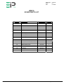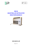
1
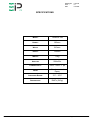
Drawing No. :- TPC314
Issue
:- A
Date
:- 02/10/07
EBAC MODEL WM150
INDUSTRIAL DEHUMIDIFIER
OWNER’S MANUAL
WM150 OWNERS MANUAL
Page 1 of 9
Drawing No. :- TPC314
Issue
:- A
Date
:- 02/10/07
INTRODUCTION
Designed for a wide range of applications, the WM150 is a rugged, industrial unit,
which utilizes an energy-efficient compressor and a compact, slim design to provide
easy efficient drying.
The WM150 has a number of special features:
•
•
•
•
•
•
•
•
•
High efficiency compressor
Ebac’s “Reverse Cycle” defrost system
Integral pump out system
Provision for permanent drainage
Exterior epoxy powder-coated finish
Extra long power cord
Free Standing or Wall Mountable
Status Indicators
Control Humidistat
The fan draws the moist air through the cold evaporator coil, which cools the air
below its dew point. Moisture forms on the evaporator coil and is collected in the
condensate tray, which is equipped with a permanent drain. The cooled air then
passes through the hot condenser coil where it is reheated using the same energy
removed during the cooling phase, plus the additional heat generated by the
compressor. The air is, therefore, discharged from the dehumidifier at a slightly
higher temperature with a lower absolute humidity than that which entered.
Continuous circulation of air through the dehumidifier gradually reduces the relative
humidity within the area.
The WM150 dehumidifier is a reliable drying unit designed to operate effectively over
a broad range of temperature and humidity conditions. An active hot gas defrost
system, controlled by an electronic timer, guarantees positive de-icing, thereby
optimizing operation at low temperatures.
WM150 OWNERS MANUAL
Page 2 of 9
Drawing No. :- TPC314
Issue
:- A
Date
:- 02/10/07
SPECIFICATIONS
MODEL:
10285GL-GB
HEIGHT:
680mm
WIDTH:
810mm
DEPTH:
305mm
WEIGHT:
75kg
AIRFLOW:
580m3/hr
POWER SUPPLY:
230V - 50Hz - 1 ph
FINISH:
Powder-coated
Epoxy
OPERATING RANGE:
3°C – 35°C
REFRIGERANT:
R407c (540g)
WM150 OWNERS MANUAL
Page 3 of 9
Drawing No. :- TPC314
Issue
:- A
Date
:- 02/10/07
OPERATION
The following procedures should be followed to test the WM150 for correct
operation:
1. After unpacking, examine all external features to confirm damage-free
shipment. Report all defects and damage at once. Connect the power cable
to a grounded 13 Amp electrical socket
CAUTION
DO NOT REMOVE COVERS WHEN THE UNIT IS IN OPERATION
2. Check dehumidification process as follows:
a. Place unit on a level surface.
b. Start up unit by switching to “ON” and turning the humidistat clockwise.
c. Check that the compressor is running.
d. Leave the machine running for 15 minutes.
e. Observe the evaporator coils through the rear upper grille, to confirm
frost formation.
f. If the air temperature is below 25ºC, an even coating of frost should
cover the entire evaporator coil.
g. If the air temperature is above 25°C, frost and/or droplets of condensed
water should cover the entire evaporator coil.
h. After continuous running time of approximately 42 minutes, unit will
enter “Reverse Cycle” defrost mode for several minutes and then
automatically return to normal operation.
3. If, after carrying out the above procedures, the unit does not appear to
function properly, refer to the Trouble Shooting section, which follows, or
contact the Factory Service Center.
CAUTION
ONCE THE UNIT HAS BEEN SWITCHED OFF, WAIT AT LEAST
5 MINUTES BEFORE RESTARTING
4. After using the WM150, turn it off for five minutes to allow the condensate
on the coils to drain into the pump reservoir.
WM150 OWNERS MANUAL
Page 4 of 9
Drawing No. :- TPC314
Issue
:- A
Date
:- 02/10/07
INSTALLATION
The WM150 Dehumidifier can be left free standing unit, alternatively can be wall
mounted for instructions on mounting the unit please read the following:
A full installation kit is included in the package to allow a problem free install. This kit
comprises of the following :1 X WM150 Dehumidifier
1 X Mounting Bracket
4 X Rawl plugs and screws
4 X M6 Hex Head Bolts, flat and spring washers
For mounting the WM150 Dehumidifier to a wall you will first need to remove the
cover from the unit and detach the wall mounting bracket from the rear of the unit by
removing the 4 bolts that secures it.
With reference to the installation drawing at the rear of this manual, maintain the
minimum clearances from adjacent objects (ie walls celings etc). Maintaining these
distances will ensure easy access for installation and maintaining the unit during the
products life
Place the wall mounting bracket onto the wall, ensuring the correct orientation, and
the bracket is level. Mark off 4 points on the wall where you will be securing the
bracket, the bracket has numerous holes and slots to allow the bracket to be
mounted at different points depending on the wall you are mounting it to. It is advised
to have the fixing points spaced out as far as possible to allow a more ridged and
secure installation.
Using a 7mm masonry bit, drill the 4 points you marked off earlier to a depth of
40mm, insert the 4 Rawl plugs into the wall that are supplied with this unit.
Secure the wall mounting bracket to the wall using the 4 brass screws supplied with
the unit.
Ensure all fixings are tight and bracket is secured to the wall.
Screw 2 X M6 Bolts into the top fixings on the bracket, only screwing them in a 2-3
turns. Lift the unit onto the bracket and hook the unit onto the bolts using the keyhole
slots in the rear of the unit do not tighten the bolts yet. Fit the 2 remaining bolts
through bottom holes in the rear of unit and into the wall mounting bracket and
tighten all 4 bolts.
Check to make sure the unit is secure to the wall mounting bracket.
Replace cover and refit all fixings that have been removed.
WM150 OWNERS MANUAL
Page 5 of 9
Drawing No. :- TPC314
Issue
:- A
Date
:- 02/10/07
ROUTINE MAINTENANCE
WARNING
ENSURE THE UNIT IS ISOLATED PRIOR TO CARRYING OUT ANY
ROUTINE MAINTENANCE
To ensure continued full efficiency of the dehumidifier, maintenance procedures
should be performed as follows:
1. Clean the surface of the evaporator and condenser coils by blowing the dirt
out from behind the fins with compressed air. Hold the nozzle of the air hose
away from the coil to avoid damaging the fins. Alternatively, vacuum clean
the coils.
WARNING:
DO NOT STEAM CLEAN REFRIGERATION
2. Remove the air filter and clean by either blowing compressed air through,
vacuuming or washing in warm water
3. Check that the fan is firmly secured to the motor shaft and that the fan
rotates freely. The fan motor is sealed for life and therefore does not
need oiling.
4. To check the refrigerant charge, run the unit for 15 minutes and briefly
remove the top cover. The evaporator coil should be evenly frost coated
across its surface. At temperatures above 25°C, the coil may be covered
with droplets of water rather than frost. Partial frosting accompanied by
frosting of the thin capillary tubes, indicates loss of refrigerant gas or low
charge. During this inspection, check visually to ensure that the pump rollers
are turning.
5. Check all wiring connections.
6. To check the operation of the defrost system, switch the machine on and
leave it running for approximately 42 minutes. The machine will then enter
“Reverse Cycle” defrost mode for approximately 4 minutes before returning
to normal operation. If the unit will not defrost, the printed circuit timer board
may be defective or the by-pass valve may be inoperable.
IF ANY OF THE PRECEDING PROBLEMS OCCUR, CONTACT THE EIP SERVICE CENTER PRIOR
TO CONTINUED OPERATION OF THE UNIT TO PREVENT PERMANENT DAMAGE.
WM150 OWNERS MANUAL
Page 6 of 9
Drawing No. :- TPC314
Issue
:- A
Date
:- 02/10/07
REPAIRS
1.
Should an electrical component fail, consult the Factory Service Center to
obtain the proper replacement part.
2.
If refrigerant gas is lost from the machine, it will be necessary to use a
Refrigeration technician to correct the fault. Contact the Factory Service
Center prior to initiating this action.
Any competent refrigeration technician will be able to service the
equipment. The following procedure must be used:
a. The source of the leak must be determined and corrected.
b. The machine should be thoroughly evacuated before recharging.
c. The unit must be recharged with refrigerant measured accurately by
weight.
d. For evacuation and recharging of the machine, use the crimped and
brazed charging stub attached to the side of the refrigerant
compressor.
The charging stub should be crimped and rebrazed after servicing.
NEVER allow permanent service valves to be fitted to any part of the
circuit. Service valves may leak causing further loss of refrigerant gas.
3.
The refrigerant compressor fitted to the dehumidifier is a durable unit that
should give many years of service. Compressor failure can result from the
machine losing its refrigerant gas. The compressor can be replaced by a
competent refrigeration technician.
Failure of the compressor can be confirmed by the following procedure:
a. Establish that power is present at the compressor terminals using a
voltmeter.
b. With the power disconnected, check the continuity of the internal
winding by using meter across the compressor terminals. An open
circuit indicates that the compressor should be replaced.
c. Check that the compressor is not grounded by establishing that a
circuit does not exist between the compressor terminals and the shell
of the compressor.
WM150 OWNERS MANUAL
Page 7 of 9
Drawing No. :- TPC314
Issue
:- A
Date
:- 02/10/07
TROUBLESHOOTING
SYMPTOM
CAUSE
Unit inoperative
1. No power to unit
Little or no airflow
1.
2.
3.
4.
Loose fan on shaft
Fan motor burnt out
Dirty refrigeration coils / filter
Loose electrical wiring
5. Fuse blown or circuit breaker
tripped
1. Insufficient air flow
2. Compressor fault
3. Loss of refrigerant gas
Little or no water
extraction
Little or no defrost when
required
1. Faulty timer
2. Faulty by-pass valve
1. Loose compressor
Unit vibrates excessively
2. Damaged fan
Water flooding inside the
machine
1. Drain pipe blocked/frozen
2. Drain pipe too high
3. Crimped or blocked tubing
REMEDY
1. Check the power from power
supply panel
1. Tighten fan
2. Replace the fan motor
3. See Routine Maintenance
Section
4. Check the wiring diagram to find
fault and repair
5. Replace the fuse or reset the
circuit breaker
1. Check all of the above
2. Contact the Factory Service
Center
3. Contact the Factory Service
Center
1. Contact the Factory Service
Center
2. Contact the Factory Service
Center
1. Tighten the nuts on the
compressor mounts
2. Replace fan
1. Clear the obstruction
2. Ensure that no section of the
drain hose is above the level of
the water outlet
3. Straighten, clear, or replace
tubing
Ebac Industrial Products Limited
St Helen Trading Estate,
Bishop Auckland,
CO. Durham
DL14 9AD.
Telephone 01388 664400 Fax 01388 662590
Website www.eipl.co.uk
WM150 OWNERS MANUAL
Page 8 of 9
Drawing No. :- TPC314
Issue
:- A
Date
:- 02/10/07
WM150
SPARE PARTS LIST
NUMBER
DESCRIPTION
PART NUMBER
QUANTITY
1
Filter
2028517
1
2
Timer
1601200
1
3
Evaporator Coil
2028401
1
4
Condenser Coil
2028400
1
5
Humidistat
3035145
1
6
Capillary Tube
3014251
2 X 48”
7
Reversing Valve
3020810
1
8
Filter Dryer
3020957
1
9
Compressor
3944914
1
10
Solenoid Coil
3030419
1
11
Run Capacitor (Compressor)
3037505
1
13
Fan Motor
3040242
1
16
Black Rubber Foot
3101436
4
17
Pump
3160148
1
18
Contactor
3930733
1
19
Rocker Switch
3035914
1
WM150 OWNERS MANUAL
Page 9 of 9