1
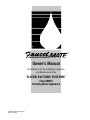
®
Owner's Manual
This Manual is for the Installation, Operation,
and Maintenance of the
®
WATER FACTORY SYSTEMS
FaucetMATE
Drinking Water Appliance
© 2002 CUNO Incorporated
98-91121 0902
INTRODUCTION
This manual explains the installation, operation and maintenance of the Water
Factory Systems’ FaucetMATE® Drinking Water Appliance. Please read each section of
this manual carefully. The specific model chosen should be appropriate for the local
water conditions and the customer’s needs. Check the Performance Data Sheet for the
performance characteristics and the conditions of use.
The Water Factory Systems’ drinking water appliances are designed to connect permanently to a home plumbing system. To ensure that the installation conforms to your
state and local plumbing codes, it is recommended that the installation be performed
by a qualified installation specialist for drinking water appliances or a licensed
plumber. Failure to install the system as instructed will VOID the warranty.
TABLE OF CONTENTS
I. Installation Instructions
A.
B.
C.
D.
E.
F.
G.
H.
I.
J.
K.
Installation precautions....................................................................................................3
Determine system location ..............................................................................................3
Prepare the area for installation ......................................................................................3
Prepare the system for installation ..................................................................................3
Locating the faucet ..........................................................................................................3
Make the faucet mounting hole........................................................................................4
Mounting the faucet ........................................................................................................4
Mounting the drinking water filtration system ................................................................4
Installing the feed water valve..........................................................................................5
Make the tubing connections ..........................................................................................5
Installing and replacing filter cartridges ..........................................................................5
II. Illustrations
1.
2.
3.
4.
System location ..............................................................................................................6
Faucet installation ............................................................................................................6
Feed water valve installation ............................................................................................7
How to use “Push In connectors ....................................................................................7
Congratulations and thank you for purchasing the Water Factory Systems’ FaucetMATE® Drinking Water System. You
are about to enjoy the benefits of high quality drinking water right in your own home. The FaucetMATE dual-stage filtration systems contain the most effective filtration media for reducing common but potentially harmful pollutants. The
FaucetMATE line consists of the FM-2 CTO for reduction of chlorine, taste and odors, the FM-2 Lead for the reduction of
lead, chlorine, taste and odors, and the FM350-DWS for the reduction of volatile organic chemicals (VOCs), MTBE, lead,
chlorine, taste and odors, sediment and mirco organisms such as cysts. All FaucetMATE systems operate on regular
household water pressure.
This manual explains the installation, operation and maintenance of your FaucetMATE Drinking Water System. Please
read each section of this manual carefully. The system is designed to connect permanently to a home plumbing system.
To assure that the installation conforms to your state and local plumbing codes, it is recommended that the installation
be performed by a qualified installation specialist for drinking water appliances or by a licensed plumber.
A. Installation Precautions
The exact placement of the various components of the system
will vary from installation to installation. The installer, in conjunction with the customer, must decide on where to place the
faucet and filtration system by balancing the home owner’s convenience with ease of installation and servicing (see Figure 1).
• The tubing must be installed in the correct inlet and outlet
fittings as labeled. Make sure not to reverse the connections.
• Do not install on a hot water line. The maximum temperature
allowed is 100°F (38°C).
C. Prepare the area for installation
• Do not install on a line with water pressure above 125 psi
(862 kPa).
Remove supplies from under the sink and stack them neatly
away from the working area if necessary.
Inspect the cold water supply line and determine if any special
fittings, in addition to what is included in the kit, are required.
• Do not use a torch or other high temperature sources near
the filtration assembly or the plastic cartridges.
NOTE: It is a good idea at this time to check the condition of
the undercounter plumbing for any existing or potential leaks.
Any items of concern should be repaired prior to installation of
the drinking water device.
• Special care must be taken when drilling the holes for the
mounting bracket. Use caution when installing near electrical
wires or water pipes.
• Protect from freezing. Drain the filtration system when the
room temperature drops to 32°F (0°C) or below.
D. Prepare the system for installation
Open the shipping carton and remove the components. Check
to see that all of the installation parts are present. They should
include the filtration system, faucet, installation hardware and
tubing.
• Do not install in direct sunlight.
• Allow a minimum of 2” (5 cm) clear space under each filter
cartridge to facilitate cartridge change.
E. Locating the faucet
• Mount the filtration system in a location that will minimize
the chance of it being struck by other items, such as waste
baskets, etc.
Select a sink or countertop location at least 2” (5 cm) in diameter on which to mount the drinking water faucet. The faucet
should be positioned so that it empties into the sink. Make certain the location directly underneath this area is free of obstruction in order to accommodate the faucet assembly. If the sink
already has a hole provided that can accommodate the faucet,
then no drilling is required and you can proceed to the section on
mounting the faucet (see Figure 1).
• The installation must comply with existing state and local
plumbing codes.
• Do not use where water is microbiologically unsafe, or with
water of unknown quality without adequate disinfection
before or after the system.
B. Determine System Location
The filtration system should be located under the sink. Never
install it in an area of the home where the temperature may drop
to freezing, because damage to the system will result.
3
F. Make the faucet mounting hole
Procedure:
1) Mark the center for the 9/16" hole.
2) Form a shallow putty dam around the hole area and fill it
with enough water to lubricate the carbide drill bit.
3) Carefully drill a pilot hole through the porcelain/enamel and
the base metal using a carbide type pilot drill. Important:
Always operate the drill with light pressure at a slow
speed (300-400 rpm).
4) Insert the pilot tip of the spring-loaded porcelain cutter into
the pilot hole.
5) Drill the porcelain/enamel using the spring-loaded
porcelain cutter, making certain a complete ring has been
cut through the porcelain/enamel to the metal base.
6) Change to the metal cutter. With a slow speed and light
pressure, cut away the inner porcelain/enamel disc down
to the base metal. Make certain that the cutter does not
touch the outer rim of the cut porcelain/enamel. Continue
with this bit to cut through the metal until the sink has
been completely penetrated.
IMPORTANT: It is mandatory that safety glasses by worn during
the sink hole drilling operations in order to prevent eye injury.
IMPORTANT: Extreme care must be taken when drilling the hole
for the faucet. The surface material is hard and brittle and easily
chipped or cracked. The manufacturer assumes no responsibility for sink damage resulting from this installation.
A wide variety of faucet mounting situations may be encountered, the most common being stainless steel and ceramic-onmetal sinks. Consult a plumber for the other materials that may
be encountered.
Before drilling the hole, always check underneath the sink to
ensure that nothing will interfere with mounting the faucet such as
reinforcing ribs, support brackets or the cabinet construction.
Stainless steel sink.
Recommended tools:
• Center punch
• Variable speed drill and high speed drill bits
• Chassis punch 9/16" size
• Protective gloves
G. Mounting the faucet
1) Remove all of the hardware from the threaded nipple of the
faucet except for the rubber washers and the chrome base
plate (See Figure 2). The rubber washer may be replaced
with a small amount of putty for a nicer appearance.
2) Put the threaded nipple through the faucet mounting hole
and position the faucet spout over the sink.
3) From below the sink/countertop, assemble the plastic
bottom washer, star washer and hex nut onto the threaded
nipple and tighten it by hand (see Figure 2).
4) After rechecking the faucet orientation, tighten the hex nut
with a 9/16” wrench until the faucet feels secure.
5) From above the sink, make any minor orientation
corrections by turning the faucet on its “flats” with a
padded adjustable wrench. Use care so as not to mar the
chrome finish.
Procedure:
1) Center punch a small indent at the center of the desired
faucet location.
2) Slowly drill the required pilot hole for the chassis punch.
3) Set up the chassis punch per the instructions and tighten
the nut to cut the desired hole size.
4) Clean up all sharp edges with a file if necessary.
Porcelain/Enamel/Ceramic sink on sheet metal or cast iron
base.
Recommended tools:
• Variable speed drill
• Porcelain cutter tool set 9/16" size
• Plumber's putty
H. Mounting the drinking water filtration system
NOTE: Be sure to locate the system where there is a minimum
of 2” (5 cm) clearance underneath it to facilitate filter cartridge
changes.
It is important to understand what is involved in this procedure. First, the glassy layer of porcelain must be penetrated
through to the base metal. Second, a center disc of porcelain
must be removed while protecting the surrounding porcelain
against chipping or fracturing. Third, the base metal must be
drilled through to complete the hole.
1) Mark the mounting screw locations on the cabinet sidewall
using the holes on the bracket as guides.
2) Drill starter holes into the sidewall.
3) Hang the filtration system onto the sidewall by fastening
wood screws through the bracket and into the mounting
surface.
IMPORTANT: When using a porcelain cutter it is critical that it
is always in a sharpened condition. Dull cutters are known to
chip sinks.
4
I. Installing the feed water valve
J. Make tubing connections
The saddle tapping valve which is supplied is designed to be
used on 3/8” - 1/2” OD soft copper tubing (plain or chromed)
and rigid metal pipe. Do not use with flexible ribbed tubing
because it requires special hardware. Optional feed valves should
be used for this purpose.
NOTE: With all of the components in place, the tubing connections
can be made. Be sure to arrange the tubing so that there are no
sharp bends. Leave some “play” in the tubing for ease of servicing.
NOTE: Try to keep the tubing from the filtration system to the
faucet as short as possible to ensure good water flow.
IMPORTANT: Some local plumbing codes may prohibit the use of
saddle-type valves. In this case, optional feed valve assemblies
should be used.
1) Connect the 1/4” orange tubing to the “Push In” male
connector on the inlet side of the filtration assembly (refer
to Figure 4 on the use of “Push In” plastic fittings).
Soft Copper Tubing Installation:
A) Turn off the cold water feed valve under the sink, or the
main feed valve for the house.
B) Before installing the saddle tapping valve, make sure the
piercing lance does not protrude beyond the rubber gasket.
See instructions on bag.
C) Place saddle tapping valve around the copper tubing and
tighten the mounting screw until the valve is tight. Be
careful not to deform the copper tubing (see Figure 3).
D) To pierce the soft copper tubing, turn the handle clockwise
until it is firmly seated. The valve is closed in this position.
E) Turn on the main supply valve to pressurize cold water line.
Check for leaks.
F) Connect a length of 1/4” orange tubing to the feedwater
valve, using the insert, plastic sleeves and brass
compression nut.
2) Connect the 1/4” blue tubing from the faucet to the
“Push In” fitting attached to the outlet connection on the
filtration assembly.
K. Installing and replacing filter cartridges
NOTE: In order to ensure proper performance, it is essential
that the filters be installed in the correct location. Use the icon
coded labels to match the filter cartridges with their corresponding filter head.
1) Close the feed water valve and lift up the faucet handle. Wait
approximately 10 seconds for the system to depressurize.
2) Twist the filter cartridge 1/4 turn to the left so that the ears
on the cartridge are able to disengage from the head.
Firmly pull the cartridge downward to remove it from the
head. It may be necessary to twist the cartridge slightly
from side to side to help free it from the head.
3) Remove the new filter cartridge from its sanitary sealed
wrapper. (Double check to see that it is the correct
replacement filter cartridge by comparing the labels.)
4) Using either tap water, food grade silicone lubricant or
glycerine, lubricate the o-ring seals to make cartridge
insertion easier.
5) Line up the cartridge ears, insert the cartridge and push it
up into the head until it is firmly seated. Twist the cartridge
1/4 turn to the right to lock it into place.
6) Open the feed water valve and carefully check for leaks.
7) Allow system to operate with the faucet open for at least 10
minutes. This will allow the cartridge to properly flush prior
to use.
Rigid Metal Pipe Installation:
A) Turn off the cold water feed valve under the sink, or the
main feed valve for the house.
B) Drill a 3/16” hole at the desired location on the metal pipe.
To prevent shock hazard, use a battery operated drill.
C) Turn the saddle tapping valve clockwise to expose the
piercing lance beyond the rubber gasket no more than 3/16”.
D) Place saddle tapping valve around the copper tubing
making sure the piercing lance is located in the hole and
tighten the mounting screw until the valve is tight (see
Figure 3).
E) Turn saddle valve handle clockwise to close valve.
F) Turn on the main supply valve to pressurize cold water line.
Check for leaks.
G) Connect a length of 1/4” orange tubing to the feedwater valve,
using the insert, plastic sleeve and brass compression nut.
5
Figure 1
Faucet
Feedwater
Valve
FM-2 & FM-2 Lead Plus
Figure 2
Rubber Washer
Chrome Base Plate
Rubber Washer
Plastic Bottom Washer
Star Washer
Hex Nut
6
Figure 3
Valve Handle Stem
Nut/Seal
Piercing Lance
Insert
Plastic Sleeve
Compression Nut
1/4" Orange Feedwater Tubing
For 3/8" OD tubing, use the side of
the bracket with the projections.
For 7/16" to 1/2" OD tubing or rigid pipe,
use the "V" side of the bracket.
Figure 4
‘Push-In’ Tubing Connector
This product is outfitted with user friendly ‘Push In’ connectors. Proper use of the connectors
is shown in the diagrams.
It is most important that the tubing selected for use with these connectors be of high quality,
exact size and roundness, and with no surface nicks or scratches. If it is necessary to cut the tubing, use a plastic tubing cutter or sharp razor knife. Make a clean square cut.
Should a leak occur at a ‘Push-In’ connector, the cause is usually defective tubing.
To Fix:
To Attach Tubing
1 Tube O-Ring
• Relieve pressure
• Release tubing
• Cut off at least 1/4” from end.
• Reattach tubing
• Confirm connection is leak free.
To Release Tubing
1
2
Push in grey collet to release tubing.
Pull tubing straight out.
2
Grey Collet
Push tubing straight in as far as it will go. Tubing is secured in.
7
Figure 5
To Faucet
Outlet Fitting with
Flow Control
Feedwater
Inlet
47-55711G2
47-55707G2
47-55707G2
From Feedwater
Source
FM-350 DWS
NOTE: Some state and local plumbing codes may prohibit the use of saddle-type valves and/or drain connections. The use of saddle-type
valves are prohibited in: Alaska, Delaware, Idaho, Kentucky, Massachusetts, Michigan, Minnesota, New Hampshire, North Dakota, Ohio,
Oregon, and South Dakota. Check your local plumbing codes for any restrictions that may apply. Massachusetts CMR 248 strictly prohibits
the use of saddle-type valves. The feedwater connection must conform to applicable plumbing codes.
8
CUNO Incorporated
400 Research Parkway
Meriden, CT 06450, U.S.A.
Toll Free: 1-800-733-1199
Worldwide: 203-237-5541
Fax: 203-238-8701
www.waterfactorysystems.com • www.cuno.com