1
TGR-SL-USB
SignaLink USB
Cable List - Rev 48
Last Update - 24 December 2013
Last Tigertronics Update - 15 November 2013
Tigertronics SignaLink USB Digital Interface - Cable
Interface Listing
SignaLink Jumper Settings & Wiring Information For Base & Mobile Radios
References to other non-USB models have been removed from the original Tigertronics document.
Warning: Tigertronics has not verified the accuracy of all of the radio wiring information that is provided here. This
information is provided for reference only and is NOT intended to replace the jumper installation procedure in the
“Connecting The Radio” section of the SignaLink Installation Manual. It is essential that you double-check this information
against your radio's manual before doing the actual installation. While it is fairly simple to install the SignaLink, it is
possible to DAMAGE YOUR RADIO or the SignaLink by incorrectly installing it!
IMPORTANT NOTES
SignaLink USB Users - The SignaLink USB is always powered by the computer's USB jack. When installing the jumpers
for the SignaLink USB using the settings shown here and in our other documentation, please disregard the PWR jumper
(do NOT install it!). All other jumper settings are the same. Note that if you mistakenly install the PWR jumper, it will
make no difference in the operation of the unit as this pin is not internally connected.
Select The Correct Diagram - When viewing the jumper settings below, BE CERTAIN THAT YOU ARE LOOKING
AT THE CORRECT DIAGRAM for the radio connector that you
will be using. For any given radio, there are likely to be different
jumper settings for the Mic, Data and Accessory Port connectors.
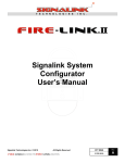
RJ-45 Mic Connectors - There is a lack of standardization in the way
that radio manufacturers number their RJ-45 mic connectors. We
have numbered our connector according to the dominant industry
standard as shown to the right. Icom and Radio Shack also follow this
standard, but Kenwood, Yaesu and some others do not. You need to
be very careful to determine how your mic connector is numbered to
avoid reversing connections!
PTT - You should verify in your radio manual that the radio PTT
requirements do not exceed the specifications of the SignaLink keying
circuit (please refer to the SignaLink manual) and that the PTT line is
“Grounded” to make the radio transmit. If your radio exceeds the
specifications listed or requires some other keying arrangement, then
please contact our Technical Support Staff for suggestions.
POWER - The SignaLink USB is always powered by the computer's USB jack. When installing the jumpers for the
SignaLink USB, please disregard the PWR jumper. All other jumper settings are the same. If you mistakenly install the
PWR jumper, everything is OK as this pin is NOT connected inside the unit.
Jumper Wire Color - The jumper wires in the diagrams below are shown in color for illustrative purposes only. The color
of the wires means nothing - they're just easier to see! The actual jumper wires that are included with the SignaLink are all
the same color and can be used to jumper any signal.
Note that the SignaLink USB is always powered by the computer, so you can disregard the PWR jumper when installing
this unit.
RECEIVE AUDIO / SPEAKER AUDIO - Receive Audio is available on the Mic, Data, and Accessory Port connectors
of most radios. If Receive Audio is not shown in the jumper settings for your radio, then consult your radio manual to see
if it is available. If it is not, then you will need to connect a mono cable between your radio's External Speaker or
headphone jack, and the "Speaker" jack on the back of the SignaLink. See the SignaLink Installation Manual for details.
SELECT A MANUFACTURER
NOTE: Please read the "Important Notes" above BEFORE you select your jumper settings. This will save time and may help
prevent you from making a mistake that could possibly damage the SignaLink or your radio. Note that the SignaLink USB does
NOT use the PWR jumper wire, so you can disregard this jumper during installation. All other jumper settings are the same.
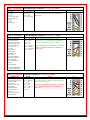
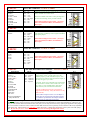
ADI
8-Pin Round Mic Connector - TGR-SL-CAB8R
Radio Models
AR-146
AR-147
AR-446
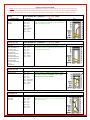
Pin-out
Pin 1 - Mic Input
Pin 2 - PTT
Pin 3 - N/C
Pin 4 - N/C
Pin 5 - N/C
Pin 6 - Speaker**
Pin 7 - N/C
Pin 8 - GND
ALINCO
8-Pin Round Mic Connector - TGR-SL-CAB8R
Radio Models
ALD-24T
ALR-22T/22HT/72T
DR-110T/112T
DR-130T/135E/135T
DR-150/235T
DR-430T/435E/435T
DR-510T/570T
DR-590T/592T/599T
DR-600T/610E/610T
DR-620E/620T
DX-70T/70TH/70EH
DX-77
DX-SR8T/E
Pin-out
Pin 1 - Mic Input
Pin 2 - PTT
Pin 3 - N/C
Pin 4 - N/C
Pin 5 - N/C
Pin 6 - N/C**
Pin 7 - GND
Pin 8 - GND
ALINCO
RJ-45 Mic Connector - TGR-SL-CABRJ4
Radio Models
DR-605E/605T
Pin-out
Pin 1 - N/C
Pin 2 - N/C
Pin 3 - N/C
Pin 4 - PTT
Pin 5 - Mic GND
Pin 6 - Mic Input
Pin 7 - GND
Pin 8 - N/C
AZDEN
8-Pin Round Mic Connector - TGR-SL-CAB8R
Radio Models
PCS-5000
PCS-6000
PCS-7000
Pin-out
Pin 1 - Mic Input
Pin 2 - GND
Pin 3 - N/C
Pin 4 - N/C
Pin 5 - N/C
Pin 6 - N/C
Pin 7 - PTT
Pin 8 - N/C
Notes
** Speaker audio is available on some models. Check
your radio manual for availability of these signals and
add the appropriate jumpers.
Notes
** Speaker audio is available on some models. Check
your radio manual for availability of these signals and
add the appropriate jumpers.
Notes
Speaker audio is available on some models. Check
your radio manual for availability of these signals
and add the appropriate jumpers.
Notes
Speaker audio is available on some models. Check your
radio manual for availability of these signals and add the
appropriate jumpers.
JP-1
JP-1
JP-1
JP-1
DRAKE
4-Pin Round Mic Connector - TGR-SL-CAB4R
Radio Models
TR-7
TR-22
TR-33
UV-3
Pin-out
Pin 1 – Mic Input
Pin 2 – PTT
Pin 3 – N/C
Pin 4 – GND
ELECRAFT
8-Pin Round Mic Connector - TGR-SL-CAB8R
Radio Models
K2
K3
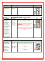
Pin-out
Pin 1 - Mic
Pin 2 - PTT
Pin 3 - NC
Pin 4 - NC
Pin 5 - NC
Pin 6 - +5VDC
Pin 7 - GND
Pin 8 - GND
Notes
Notes
The Mic jack on the K2 can be wired a number of
different ways, so before installing the jumper wires,
you MUST verify that the pin-out of your K2 matches
that shown here.
JP-1
JP-1
ELECRAFT
Rear Panel Audio In, Audio Out and PTT connectors - TGR-SL-CABK3
Radio Models
K3 only
Pin-out
Pin 1 - SPKR
Pin 2 - GND
Pin 3 - MIC
Pin 4 - PTT
Pin 5 - GND
Pin 6 - GND
Pin 7 - N/C
Pin 8 - N/C
Check the SLMODK3
Jumper Module list
Notes
Some customers have found that the K3's "Line In" gain
(menu setting) is set to zero by default, thereby resulting
in no power output when transmitting. If up experience
this problem, then please consult your radio manual for
instructions on turning up this control.
Note that the K3 also has a menu setting for the "Line
Out" level, which can be turned up if needed to increase
the RX Audio going into the SignaLink
ELECRAFT
Mic Connector - TGR-SL-CABKX3
Radio Models
KX3 only
Pin-out
Pin 1 - MIC
Pin 2 - PTT
Pin 3 - GND
Pin 4 - N/C
Pin 5 - N/C
Pin 6 - N/C
Pin 7 - N/C
Pin 8 - N/C
Check the SLMODKX3
Jumper Module list
JP-1
Notes
Two cable connections are required from the SignaLink to the
Elecraft KX3 as follows:
Connect the RJ-45 end of the SLCABKX3 radio cable to
the SignaLink’s “Radio” connector. Connect the 4-pin
right-angle TRRS plug to the KX3’s “Mic” jack, being
sure to fully insert the plug.
Connect the supplied right-angle mono audio cable
between the SignaLink’s “SPKR” jack, and the KX3’s
“Phones” jack. Be sure that both plugs are fully inserted.
KX3 Radio Settings:
1 - The “Mic Bias” setting in the KX3’s menu system should be
turned OFF if you are using jumper wires. This setting can be
left ON if you are using our SLMODKX3 jumper module as it
has a built-in DC blocking capacitor.
2 - The “Mic Btn” setting should be set to either “PTT”, or
“PTT Up.Dn.”.
3 - We recommend turning the KX3’s “Audio Effects” feature
OFF, as it will likely cause receive problems during digital
operation.
JP-1
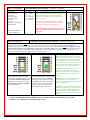
ICOM
4-Pin Round Mic Connector - TGR-SL-CAB4R
Radio Models
IC-22
IC-202/215/245/280
IC-402
IC-502/551
IC-701
Pin-out
Pin 1 – Mic Input
Pin 2 – PTT
Pin 3 – N/C
Pin 4 – GND
ICOM
8-Pin Round Mic Connector - TGR-SL-CAB8R
Radio Models
IC-22U/25/27/28
IC-37A/38A/375
IC-45/47/48
IC-228/229/251AE
IC-255/260/271/290
IC-471/475/490
IC-505/551/560/575
IC-707/718/720/725/726
IC-728/729/730/735
IC-736/737/738/740/745
IC-746/746PRO
IC-751
IC-756/756PRO
IC-756PROII/PROIII
IC-761/765/775/781
IC-820H/901/910
IC-1201/1271/1275
IC-2400/2500
IC-3200/3210/3220/3230
IC-7400/7600/7700/7800
Pin-out
Pin 1 – Mic Input
Pin 2 – N/C**
Pin 3 – N/C
Pin 4 – N/C
Pin 5 – PTT
Pin 6 – GND
Pin 7 – GND
Pin 8 – Speaker**
Notes
Notes
**Speaker audio (usually Pin #8) is available on some
models. Check your radio manual for availability of
these signals and add the appropriate jumpers.
JP-1
JP-1
IMPORTANT: This diagram is for the MIC JACK
only. If the SignaLink is attached to your radio's 8-pin
Accessory Port, then please see the diagram below
under "8-pin DIN Accessory Port Connector".
Check Other Listings for these radios - you may be
able to use the DIN, PACKET, ACCESSORY, or
DATA jack
Check the SLMOD8RI
Jumper Module list
ICOM
RJ-45 Mic Connector - TGR-SL-CABRJ4
Radio Models
IC-207H**/208H**
IC-281A/281E/281H
IC-703/706/706MKII
IC-2000
IC-2100H**/2200H**
IC-2300H**
IC-2700**/2720H**
IC-2800**/2820**
IC-7000**
IC-V8000**
ID-800H** /880**
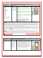
Pin-out
Pin 1 – +8V***
Pin 2 – N/C
Pin 3 – Speaker***
Pin 4 – PTT
Pin 5 – GND (mic)
Pin 6 – Mic Input
Pin 7 – GND
Pin 8 – N/C
Notes
***Speaker audio is available on some models. Check
your radio manual for availability of these signals and
add the appropriate jumpers.
**Speaker Audio is NOT available on the Mic jack of
this radio.
Check Other Listings for these radios - you may be
able to use the DIN, PACKET, ACCESSORY, or
DATA jack
JP-1
ICOM
6-Pin Mini DIN Data Port Connector - TGR-SL-CAB6PM
Radio Models
IC-207H/208H
IC-2720H
IC-2800****
IC-2820
IC-703
IC-706MKIIG**
IC-746PRO***
IC-7000***
IC-7100
IC-7400
IC-910H##
ID-880
IC-9100
Pin-out
Pin 1 – Data In
Pin 2 – Ground
Pin 3 – PTT
Pin 4 – 9600 Out
Pin 5 – 1200 Out
Pin 6 – Squelch
Notes
For special signals requiring un-filtered
"discriminator" audio, you will need to move the
"SPKR" jumper to pin #4 (9600 baud output). Note
that some newer radios do NOT provide this output, so
this may not apply to your radio.
JP-1
**IC-706MKIIG - If you are using the Data Port on
this radio, then you must set menu #29 "9600
Mode" to 1200.
***IC-746PRO / IC-7000 - Some users have reported
that this radio has a very sensitive Data Port, making
power adjustments with the SignaLink USB's TX knob
somewhat touchy.
Check the SLMOD6PM
Jumper Module list
****Mic audio is NOT muted on this radio.
## IC-910H: You will need to connect the
SignaLink to the “Main” data port connection on
this radio (not the “Sub” port)
***NOTE: The SignaLink USB's TX control is "touchy", making it difficult to control my RF power - This is most likely because the radio’s Mic,
Data or Accy Port gain control is set too high, but before continuing, please be sure that you have NOT installed special jumper JP3 inside the SignaLink.
This jumper is rarely needed, and will normally cause the SignaLink to provide too much audio to the radio making adjustment of the TX knob difficult.
If the SignaLink is attached to your radio's Mic jack, then you can resolve this issue by turning the radio’s Mic Gain control down. If the SignaLink is
attached to the radio's Data or Accy Port, then your radio likely has a menu setting or trimmer to adjust the gain. This gain adjustment is often called “Packet
Input Level” or “Packet Gain”, but may have another name, so check your radio manual carefully. Note that the radio's Mic Gain control on some older
radios may also affect the Data/Accy Port (TS-440 for example), so you should check this as well.
If the above solutions don't help, then we suggest that you install Special Jumper JP4 inside the SignaLink and LOWER the software "Wave" control for the
SignaLink's sound card. Note that the "wave" control is the "Applications" volume control if you are using Windows Vista, or Windows 7. The "Wave"
control can be lowered to just above the point where the SignaLink's PTT LED turns OFF, so as to provide minimal TX Audio to the radio while insuring
that the SignaLink's PTT circuit functions correctly. We recommend finding this threshold while transmitting a steady test tone, and with the SignaLink's
Delay knob set to minimum.
***NOTE: If you are using an ICOM IC-7000, IC-746PRO, or Yaesu FT-450, please note that some customers have reported that these radios have
unusually sensitive Data Ports, which can make adjustment of the SignaLink's TX knob somewhat difficult. If this is the case with your radio (and the
solutions listed above don't work), then you can easily resolve the issue by replacing the SignaLink's "Mic" jumper wire with a standard 1/4 watt size
resistor. Both a 47K and 100K resistor have been reported by several customers to allow easy adjustment of the power level. Please note that you **DO
NOT** solder this resistor. It simply plugs into the JP1 socket in place of the MIC jumper wire. Be sure that you use a 1/4 watt size resistor, so that you
do not damage the SignaLink's socket!
ICOM
24 Pin DIN Accessory Port Connector
Radio Models
IC-251AE
IC-730
IC-751
Pin-out
Pin 1 - N/C
Pin 2 - +13.8V
Pin 3 - PTT
Pin 4 - AF Out
Pin 5 - Mic Input
Pin 6 - N/C
Pin 7 - N/C
Pin 8 - GND
Pins 9-24 N/C
Notes
24-pin DIN Accessory Port Connector - Tigertronics
does not manufacture a cable for the ICOM 24-pin
Accessory Port connector, but you can easily build one
using our un-terminated radio cable (p/n
SLCABNC). To build your cable, simply wire it
straight-through for pin numbers 1-8 (Pin #1 to Pin #1,
Pin #2 to Pin #2, etc.). Note that your cable MUST be
wired straight-through or the jumper settings shown
below will NOT work, and you might DAMAGE
YOUR RADIO OR THE SIGNALINK!
Pins marked as "N/C" are not used by the SignaLink, but
might be connected internally inside the radio.
JP-1
ICOM
8-Pin DIN Accessory Port Connector - TGR-SL-CAB8PD
Radio Models
IC-275A
IC-575A/H
IC-707
IC-725/726/728/729
IC-735/736/737/738
IC-7400
IC-746**
IC-746 PRO**
IC-756 / 756PRO
IC-756 PROII / III
IC-761/765
IC-775/775DSP
IC-781
IC-7600/7700/7800
IC-820H***/821H
IC-910H
IC-M600
IC-M700 PRO
IC-M710
IC-M802
Pin-out
Pin 1 - RTTY or N/C
Pin 2 - Ground
Pin 3 - Send
Pin 4 - Mod In
Pin 5 - AF Out
Pin 6 - Squelch
Pin 7 - +13.8V
Pin 8 - ALC
Check the
SLMOD8PD
Jumper Module list
Notes
IMPORTANT: This diagram is for the ACCY
PORT only. If the SignaLink is attached to your
radio's 8-pin Round Mic Jack, then please see
the diagram above under "8-Pin Round MIC
Connector".
IC-756PRO users should use digital mode "DUSB" or "D-LSB".
**Some customers have reported that the IC-746
(early model only) does NOT mute the Mic when
keyed from the Accy Port. If this is the case with
your radio, then you will need to turn the radio's
Mic Gain down and/or unplug the microphone.
**Due to the design of the IC-746PRO, this jack
does NOT support VHF operation. If you want to
operate both HF and VHF, then you'll need to use
the 6-pin mini-DIN Data Port instead.
**IC-746PRO users should use "USB/LSB Data"
mode (not regular USB/LSB).
***IC-820H users need to set the Modulation
Input Sensitivity switch to "Low", and the Baud
Rate Selection switch to "AMOD".
ICOM
13-Pin DIN Accessory Port Connector - TGR-SL-CAB13I
Radio Models
IC-703
IC-706
IC-706 MkII
IC-706 MkIIg
IC-718***
IC-970
IC-7000**
IC-7100
IC-7200
IC-7410
IC-9100
Pin-out
Tigertronics
manufactures a
special cable for
ICOM 13-pin
Accessory
Ports. If you
would like to
build your own
13-pin cable (not
recommended!),
please contact our
Technical Support
Staff for pin-out
and wiring
information.
Check the SLMOD13I
Jumper Module list
Japan Radio Company
Radio Models
JST-145
JST-245
Pin-out
Pin 1 - N/C
Pin 2 - N/C
Pin 3 - N/C
Pin 4 - +9V
Pin 5 - GND
Pin 6 - PTT
Pin 7 - Mic GND
Pin 8 - Mic Input
Notes
For VHF operation on the IC-706 and IC-706MKII you
will need to move the PTT jumper to Pin #4.
JP-1
JP-1
For VHF/UHF operation on the IC-706MKIIG and IC7000, you should turn the following menu item to OFF:
Item #30 for IC-706MKIIG
Item #20 for IC-7000
This will force the radio to use the same PTT pin for all
bands so will not need to change the SignaLink's jumper
settings.
***This radio does NOT mute the Mic jack when using
the Accy Port, so you will need to turn the Mic Gain
down.
**This radio does NOT mute the Mic jack when using
the Accy Port, so you will need to turn the Mic Gain
down, or use the 6-pin Mini Din Data Port instead.
8-Pin Round Mic Connector - TGR-SL-CAB8R
Notes
JP-1
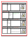
KENWOOD
4-Pin Round Mic Connector - TGR-SL-CAB4R
Radio Models
TR-7200A
TR-7400A
TR-7500
TS-120S/130S/180S
TS-511S/520/530
TS-600
TS-700
TS-820/830
Pin-out
Pin 1 – Mic Input
Pin 2 – PTT
Pin 3 – GND
Pin 4 – Mic GND
Notes
Check Other Listings for these radios - you may be
able to use the DIN, PACKET, ACCESSORY, or
DATA jack
KENWOOD
8-Pin Round Mic Connector - TGR-SL-CAB8R
Radio Models
TM-201/211/221/231
TM-241/2530/2550
TM-321/331/3530/401
TM-421/431/441/521
TM-531/541/621/631
TM-701/721/731
TM-2570
TR-50/751/851
TS-50/60/140
TS-430/440/450
TS-570/590
TS-660/670/680/690
TS-701/711/780/790
TS-811/850/870
TS-930/940/950/990
TS-2000
TW-4000/4100
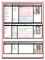
Pin-out
Pin 1 – Mic Input
Pin 2 – PTT
Pin 3 – N/C
Pin 4 – N/C
Pin 5 – 8 VDC**
Pin 6 – Speaker**
Pin 7 – Mic GND
Pin 8 – GND
Notes
** Speaker audio is not available on some
models. Check your radio manual for availability of
these signals and add the appropriate jumpers.
JP-1
JP-1
Check Other Listings for these radios - you may be
able to use the DIN, PACKET, ACCESSORY, or
DATA jack
Check the SLMOD8RK
Jumper Module list
KENWOOD
RJ-45 Mic Connector - TGR-SL-CABRJ4
Radio Models
TK-7102H
TM-251/255/261/271/281
TM-451/455/461
TM-641/642
TM-732/733/741/742
TM-941/942
TM-D700/D700A
TM-D710/710A/E
TM-G707
TM-V7A/V71A/V708
TS-480HX/SAT
Pin-out
Pin 1 – NC
Pin 2 – Speaker**
Pin 3 – Mic
Pin 4 – GND
Pin 5 – PTT
Pin 6 – GND
Pin 7 – +8V**
Pin 8 – NC
Notes
**Speaker audio is available on some models. Check
your radio manual for availability of these features and
add the appropriate jumpers.
Check Other Listings for these radios - you may be
able to use the DIN, PACKET, ACCESSORY, or
DATA jack
JP-1
KENWOOD
6-Pin Mini DIN Port Connector - TGR-SL-CAB6PM
Radio Models
TM-251/255
TM-271**/271A**
TM-451/455
TM-D700/D700A
TM-D710/710A/E
TM-G707
TM-733A
TM-V7/V7A/V71A/V708
TS-480HX/SAT
Pin-out
Pin 1 – Data In
Pin 2 – Ground
Pin 3 – PTT
Pin 4 – 9600 Out
Pin 5 – 1200 Out
Pin 6 – Squelch
JP-1
**Only European models of the TM-271 and TM271A have the 6-pin mini-DIN Data Port. All other
models will need to use the RJ-45 Mic cable.
Check Other Listings for these radios - you may be
able to use the DIN, PACKET, ACCESSORY, or
DATA jack
Check the SLMOD6PM
Jumper Module list
KENWOOD
Notes
For special signals requiring un-filtered "discriminator"
audio, you will need to move the "SPKR" jumper to
pin #4 (9600 baud output). Note that some newer
radios do NOT provide this output, so this may not
apply to your radio.
13-Pin DIN Accessory Port Connector - TGR-SL-CAB13K
Our 13-pin cable works with ALL Kenwood radio's that have a 13-pin Accessory Port, however there are two possible jumper
settings. If your radio is not listed in Figure 1 or Figure 2, then you will need to try both jumper settings to determine which PTT
configuration your radio requires. We suggest that you try the settings in Figure 1 first. Your radio will NOT be damaged if you install
the PTT jumper using the wrong configuration - you just won’t be able to transmit! After you have installed the jumpers, be sure to
set the sound card audio levels as outlined in the SignaLink manual. If you do not set the levels correctly, then the SignaLink may not
transmit, and you might mistake the problem for incorrect jumper settings.
Figure 1
Figure 2
Notes
TS-2000 users should set Menu 50F to 1200
Baud. Menu 50B can be used to increase the
radio's power output if it is too low. We suggest
that you change these menu items even if they
already appear to be set correctly. Set 50B to
zero, and then to five. Set 50F to 9600, and then
to 1200. To increase the Receive Audio Level
on the TS-2000, you can adjust menu 50C.
TS-570 users should set Menu #33 to 1 or 2 (a
setting of zero will result in no transmit
power). Menu #34 should be set at 4-5 and can
be increased to provide more Receive Audio if
needed.
This configuration is the most common
and works with early Kenwood radios such
as the TS-140, TS-450S, TS-870 and TS950. Some newer radios such as the TS570D, TS-590S, TS-990 and TS-2000/X
also use these settings.
This configuration is less common and is
used by some newer radios (TS-690 for
example) and some older radios such as
the TS-440. These settings are identical
to those in Figure 1, except for the PTT
jumper, which has been replaced by a
diode module (supplied with cable).
TS-940 users need to use the jumper settings
shown in figure 1, except for the PTT
jumper. The PTT jumper should be connected
to pin #4 instead of pin #3.
TS-440 users please note that your radio's Mic
Gain control will affect your power output. We
suggest setting this control to 50% and then
adjust it as needed so that the SignaLink's TX
knob can be used to adjust the power output
properly.
* Can use the SLMOD13K Jumper Module for Kenwood radios that have the 13 Pin Din Accessory Port
Connector - See additional notes in Module Jumper section
MIDLAND
4-Pin Round Mic Connector - TGR-SL-CAB4R
Radio Models
13-510
Pin-out
Pin 1 – Mic Input
Pin 2 – GND
Pin 3 – N/C
Pin 4 – PTT
RADIO SHACK
Radio Models
HTX-212
HTX-242
Notes
JP-1
RJ-45 Mic Connector - TGR-SL-CABRJ4
Pin-out
Pin 1 – N/C
Pin 2 – GND
Pin 3 – N/C
Pin 4 – N/C
Pin 5 – Mic Input
Pin 6 – PTT
Pin 7 – N/C
Pin 8 – N/C
Notes
Speaker audio is available on some
models. Check your radio manual for
availability of these signals and add the
appropriate jumpers.
SGC
8-Pin Round Mic Connector - TGR-SL-CAB8R
Radio Models
SGC-2020
Pin-out
Pin 1 – Mic
Pin 2 – PTT
Pin 3 – N/C
Pin 4 – N/C
Pin 5 – N/C
Pin 6 – RX Audio
Pin 7 – Mic GND
Pin 8 – GND
TEN-TEC
4-Pin Round Mic Connector - TGR-SL-CAB4R
Radio Models
Pegasus
Omni VI
Scout
Pin-out
Pin 1 – Mic Input
Pin 2 – GND
Pin 3 – PTT
Pin 4 – N/C
Notes
Notes
These jumper settings work with most Ten-Tec Mic
jacks (not just the Pegasus). However you should verify
that your radio has the same pin-out before installing
them.
Check Other Listings for these radios - you may be able
to use the DIN, PACKET, ACCESSORY, or DATA
jack
JP-1
JP-1
JP-1
TEN-TEC
5-Pin DIN Accessory Connector - TGR-SL-CAB5PD
Radio Models
Argonaut V
Jupiter
Omni VII
Pegasus
Pin-out
Pin 1 - Mic Input
Pin 2 - GND
Pin 3 - PTT
Pin 4 - AF Output
Pin 5 - NC
Notes
The Ten-Tec Jupiter must be in "Line" to use the
ACCY jack (set in radio menu).
JP-1
Check the SLMOD5PD
Jumper Module list
TEN-TEC
8-Pin DIN Accessory Connector - TGR-SL-CAB8PD
Radio Models
Eagle
Orion**
Orion II ***
Pin-out
Pin 1 - Aux In
Pin 2 - GND
Pin 3 - PTT
Pin 4 - Line Out**
Pin 5 - NC
Pin 6 - Line Out**
Pin 7 - FSK
Pin 8 - NC
TEN-TEC Delta II Users: Our 8-pin
DIN cable is NOT compatible with
the TEN-TEC Delta II. You must
connect the SignaLink to this radio's
4-pin Mic jack.
Notes
**On the original Orion, the "Audio"
menu determines what audio is available
on pins 4 and 6, so the SPKR jumper will
need to be set accordingly.
JP-1
***On the Orion II, Pin #4 is ALWAYS
the audio output. Can use the
SLMOD5PD Plug & Play per Tigertonics
e-mail of 8June2011
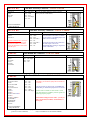
YAESU
4-Pin Round Mic Connector - TGR-SL-CAB4R
Radio Models
FT-7B
FT-101
FT-101ZD
FT-221
FT-227R
FT-901DM
Pin-out
Pin 1 – GND
Pin 2 – Mic Input
Pin 3 – PTT
Pin 4 – N/C
Notes
YAESU
8-Pin Round Mic Connector - TGR-SL-CAB8R
Radio Models
FT-1
FT-102/107/107M
FT-290
FT-707/736/736R
FT-747/757
FT-757GX/767GX
FT-840
FT-847**
FT-890**
FT-920**/950**/980**
FT-990**
FT-1000**/1000D**
FT-1000MP**
FT-2000/2200
FTDX5000**
FT-5100
Pin-out
Pin 1 – N/C
Pin 2 – N/C
Pin 3 – N/C
Pin 4 – N/C
Pin 5 – N/C
Pin 6 – PTT
Pin 7 – GND
Pin 8 – Mic Input
Notes
**On the FT-890, FT-980, FT-990, and the FT-1000
and 1000D, you should also jumper Pin #2 and Pin #5
to Ground.
**On the FT-847, FT-920, FT-950, FT-1000MP and
FTDX5000, you should also jumper Pin #5 to Ground.
Speaker audio is available on some models. Check
your radio manual for availability of these signals and
add the appropriate jumpers.
Check Other Listings for these radios - you may be
able to use the DIN, PACKET, ACCESSORY, or
DATA jack
Check the SLMOD8RY
Jumper Module list
When using the SLMOD8RY - check jumpers: G1 + G2 installed for: FT-890/980/990/1000/1000D
(picture in section on modules)
Only G1 installed for: FT-847/920/950/1000MP
JP-1
JP-1
YAESU
RJ-11 Mic Connector - TGR-SL-CABRJ1
Radio Models
FT-90/90R
FT-100**
FT-1500M
FT-1802 / 1900R
FT-2600
FT-2800M
FT-2900R
FT-7800R/7900R
FTM-350
Pin-out
Pin 1 – N/C
Pin 2 – N/C
Pin 3 – +9V
Pin 4 – GND
Pin 5 – Mic Input
Pin 6 – SW1
Pin 7 – N/C
Pin 8 – N/C
YAESU
RJ-45 Mic Connector - TGR-SL-CABRJ4
Radio Models
FT-2400
FT-2500
Pin-out
Pin 1 – N/C
Pin 2 – Speaker
Pin 3 – PTT
Pin 4 – Mic Input
Pin 5 – GND
Pin 6 – N/C
Pin 7 – N/C
Pin 8 – N/C
Notes
**With the FT-100, the PTT jumper MUST be replaced
with a standard 1/4 watt 27k resistor.
JP-1
Other Yaesu models with an RJ-11 Mic jack might also
use these same settings (check your radio manual).
Check Other Listings for these radios - you may be
able to use the DIN, PACKET, ACCESSORY, or
DATA jack
Notes
Speaker audio is available on some models. Check your
radio manual for availability of these signals and add the
appropriate jumpers.
JP-1
Check Other Listings for these radios - you may be
able to use the DIN, PACKET, ACCESSORY, or
DATA jack
YAESU
RJ-45 Mic Connector - TGR-SL-CABRJ4
Radio Models
FT-450
FT-600
FT-817
FT-897
FT-900
Pin-out
Pin 1 – N/C
Pin 2 – N/C
Pin 3 – N/C
Pin 4 – Mic GND
Pin 5 – Mic
Pin 6 – PTT
Pin 7 – GND
Pin 8 – N/C
Notes
Receive Audio is not available on this connector.
JP-1
Check Other Listings for these radios - you may be
able to use the DIN, PACKET, ACCESSORY, or
DATA jack
YAESU
6-Pin Mini DIN Data Port Connector - TGR-SL-CAB6PM
Radio Models
FT-100/100D
FT-450***
FT-817/817ND
FT-840**/847**
FT-857/897
FT-950**
FT-1500M
FT-7100/7800R
FT-7900R
FT-8100/8500
FT-8800R/8900R
FTDX-1200
FTDX-3000
FTM-350**
Pin-out
Pin 1 – Data In
Pin 2 – Ground
Pin 3 – PTT
Pin 4 – 9600 Out
Pin 5 – 1200 Out
Pin 6 – Squelch
Notes
For special signals requiring un-filtered
"discriminator" audio, you will need to move the
"SPKR" jumper to pin #4 (9600 baud output). Note
that some newer radios do NOT provide this output, so
this may not apply to your radio.
JP-1
**FT-950 - Some users of this radio have reported that
the Notch Filter is turned on after a hard reset. If you
see a "hole" in your waterfall display, then please
make sure that your Notch Filter is turned OFF.
**On the FT-840 and FT-847 the 6 pin Data Port
supports FM & LSB only. It may also function on only
VHF (Not HF).
**The FTM-350 requires Yaesu's CT-141 adapter to
convert from it's (unusual) 8-pin mini-DIN connector
to a standard 6-pin mini-DIN. This adapter should be
available from any authorized Yaesu dealer.
***NOTE: If you are using an ICOM IC-7000, IC-746PRO, or Yaesu FT-450, please note that some customers have reported that these
radios have unusually sensitive Data Ports, which can make adjustment of the SignaLink's TX knob somewhat difficult. If this is the case
with your radio (and the solutions listed above don't work), then you can easily resolve the issue by replacing the SignaLink's "Mic" jumper
wire with a standard 1/4 watt size resistor. Both a 47K and 100K resistor have been reported by several customers to allow easy adjustment
of the power level. Please note that you **DO NOT** solder this resistor. It simply plugs into the JP1 socket in place of the MIC jumper
wire. Be sure that you use a 1/4 watt size resistor, so that you do not damage the SignaLink's socket!
Check the SLMOD6PM
Jumper Module list
YAESU
5-Pin DIN Packet Connector - TGR-SL-CAB5PD
Radio Models
FT-920*
FT-1000***
FT-1000D***
FT-1000MP##
FT-1000MPMKV**
FT-1000MPMKV-Field**
FT-2000
FTDX-5000/D/MP
FTDX-9000/D/MP
Pin-out
Pin 1 – Data In
Pin 2 – GND
Pin 3 – PTT
Pin 4 – Data Out
Pin 5 – NC
Notes
JP-1
*On the FT-920, the AFSK/FSK switch MUST be set to
AFSK, and you must be in "Data" mode (push the front panel
"Data" button). The Mic Gain control appears to affect the
operation of the Packet jack, so we suggest setting this to
50% and then adjusting as needed..
**The FT-1000MPMKV and FT-1000MKV Field MUST be
in "Packet" mode (NOT USB!) for digital operation. For
PSK31 or other "USB" digital modes, you'll need to set your
radio's "User Mode" (selection 8-6) to "PS31U". This will
configure the radio to look at the Packet jack and use the
correct side band for PSK31. For more detailed information
on this (including settings for other modes), see "Digital
Modem Operation" in your radio manual.
***The 5-pin DIN jack on this radio supports only FM and
LSB, which are not compatible with the majority of digital
modes. We recommend connecting the SignaLink to the Mic
jack instead.
Check the SLMOD5PD
Jumper Module List
## A link to detailed setup information for this radio is
available on the TigerTronics web site.
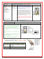
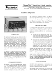
YAESU FT-847 ONLY
3.5 mm Stereo "Data I/O" Jack - TGR-SL-CABNC
Notes
For the FT-847, we recommend that you attach the SignaLink
to the "Data I/O" jack. This jack works for all modes and will
let you keep your microphone plugged into the radio. We do
not stock a cable for this jack however, so you will need to
build your own using one of our un-terminated radio
cables. The picture shows how to wire this cable and install
the jumper wires.
Notes:
1. R1 = 2.7k 1/4 watt resistor, C1 = 0.1uf non-polarized
capacitor
2. To prevent damage to socket JP1, the diameter of R1 and
C1's leads should be no larger than those of the supplied
jumper wires (24 gauge).
3. The wire colors shown are for our un-terminated ("NC"
cable. Other cables may not be wired the same.
Unterminated RJ-45 Cable - TGR-SL-CABNC
3ft Length
18 Inch Length
2ft Length
Cable Lengths
SLCAB13I SLCAB13K SLCAB5PD
SLCAB6PM SLCAB8PD SLCABK3
SLCABNC
SLCAB4R SLCAB8R SLCABRJ1
SLCABRJ4
JP-1
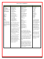
PLUG-N-PLAY MODULES
SLMOD6PM
ICOM
IC-207H
IC-208H
IC-2720H
IC-2800
IC-2820
IC-703
IC-706MKIIG
IC-746PRO
IC-7000
IC-7400
IC-910H
KENWOOD
TM-251
TM-271**
TM-271A**
TM-451
TM-D700
TM-D700A
TM-D710
TM-D710A
TM-D710E
TM-G707
TM-733A
TM-V7
TM-V7A,
TM-V71A
TS-480HX
TS-480SAT
**European only
YAESU
FT-100
FT-100D
FT-817
FT-817ND
FT-450
FT-847**
FT-857
FT-897
FT-950
FT-1500M
FT-7100
FT-7800R
FT-8100
FT-8800R
FT-8900R
**Data Port supports
VHF & UHF Packet
only.
SLMOD8PD
ICOM
IC-275A
IC-707
IC-725
IC-728
IC-729
IC-735
IC-736
IC-737
IC-7400
IC-746
IC-746PRO**
IC-756
IC-756PRO
IC-756PROII
IC-756PROIII
IC-761
IC-765
IC-775
IC-775DSP
IC-781
IC-7600
IC-7700
IC-7800
IC-820H
IC-821H
IC-910H
IC-M700PRO
IC-M710
IC-M802
**This jack supports HF
operation only. If you
want to operate both HF
and VHF, then you'll need
to use the 6-pin mini-DIN
Data Port instead.
SLMODKX3
SLMOD13I
ICOM
IC-703
IC-706
IC-706MKII
IC-706MKIIG
IC-718
IC-7000**
IC-7200
SLMOD13K
NOTE: If your radio is not listed
below, then we recommend trying
jumper setting #1 first, and then
setting #2. You will NOT damage
your radio or the SignaLink if you
use the wrong jumper settings, but
your radio will not transmit properly
(no output power, "hot" Mic, etc.).
**This radio does
NOT mute the Mic
jack when using the
13-pin Accy Port, so
we recommend
using the 6-pin Mini
Din Data Port
instead.
==========
Setting #1 - This configuration is
the most common and works with
early Kenwood radios such as the
TS-140, TS-450S,
TS-870 and TS950. Some newer
radios such as the
TS-570D, TS-590S, and TS-2000/X
also use this setting.
===========
Setting #2 - This
configuration is
less common and
is used by some
newer radios (TS-690 for example),
and some older radios such as the
TS-440.
===========
Setting #3 - This configuration
works with the TS-940 only.
This jumper module is compatible with our Elecraft KX3 radio cable only
SLMODK3
This jumper module
is compatible with
our rear panel
Elecraft K3 radio
cable only (p/n
SLCABK3 or
SLUSBK3).
PLUG-N-PLAY MODULES
SLMOD5PD
YAESU
FT-920
FT-1000MP
FT-1000MPMKV
FT-1000MPMKV Field
FT-2000
FTDX-5000/D/MP
FTDX-9000/D/MP
TEN-TEC
Argonaut V
Jupiter
Omni VII
Pegasus
Eagle**
Orion**
Orion II**
**These radio's use an
8-pin DIN radio cable,
but the jumper settings
required are the same as
those used by the 5-pin
DIN cable.
SLMOD8RI
ICOM
IC-1201/1271/1275
IC-22U/25/27/28
IC-228/229/251AE
IC-255/260/271/290
IC-2400/2500
IC-37A/38A/375
IC-3200/3210/3220
IC-45/47/48
IC-471/475/490
IC-505/551/560/575
IC-707/718/720/725/726
IC-728/729/730/735
IC-736/737/738/740/745
IC-746/746PRO
IC-756/756PRO
IC-756PROII/PROIII
IC-7400/7700/7800
IC-751/761/765/775/781
IC-820H/901 /910
PWR / SPKR Jumper Settings - To
maintain compatibility with as
many radios as possible, this
jumper module has two small
jumpers that can be set to enable
Power and Speaker Audio.
PWR - This jumper is *NOT* used
with the SignaLink USB, but can
be installed to power the older
SignaLink SL-1 or SL-1+ model
from your radio if there is
sufficient power available on Pin
#2 of the Mic connector (check
your radio manual).
SPKR - This jumper should only
be installed if your radio has
Speaker Audio on Pin #8 of the
Mic jack (check your radio
manual). If Speaker Audio isn't
available, then you'll need to
connect an audio cable between the
radio and the SignaLink as
described in the SignaLink
Installation Manual.
SLMOD8RK
KENWOOD
TM-201/211/221/231
TM-241/2530/2550
TM-2570
TM-321/331/3530/401
TM-421/431/441/521
TM-531/541/621/631
TM-701/721/731
TR-50/751/851
TS-50/60/140/430/440
TS-450/570/660/670
TS-680/690/701/711
TS-780/790/811/850
TS-870/930/940/950
TS-2000
TW-4000/4100
SLMOD8RY
YAESU
FT-107/107M
FT-736/736R
FT-747/757
FT-757GX
FT-767GX
FT-840/847
FT-890
FT-920/950
FT-980/990
FT-1000/1000D
FT-1000MP
FT-2000
FT-dx5000
FT-2000
FT-5100
ALINCO
ALD-24T
ALR-22T/22HT/72T
DR-110T/112T
DR-130T/135E/135T
DR-150/235T
DR-430T/435E/435T
DR-510T/570T
DR-590T/592T/599T
DR-600T /610E/610T
DR-620E/620T
DX-70T /70TH/70EH
DX-77
G1 / G2 Jumper Settings To maintain compatibility
with as many radios as
possible, this jumper module
has two small jumpers that
can be set to provide
additional Ground ("G")
connections needed by some
radios (see below). These
two jumpers should be
installed as follows for the
following radios only. Do
*NOT* install either jumper
if your radio isn't listed
below:
PWR / SPKR Jumper Settings - To
maintain compatibility with as many
radios as possible, this jumper module
has two small jumpers that can be set to
enable Power and Speaker Audio.
PWR - This jumper is *NOT* used with
the SignaLink USB, but can be installed
to power the older SignaLink SL-1 or
SL-1+ model from your radio if there is
sufficient power available on Pin #5 of
the Mic connector (check your radio
manual).
SPKR - This jumper should only be
installed if your radio has Speaker Audio
on Pin #6 of the Mic jack (check your
radio manual). If Speaker Audio isn't
available, then you'll need to connect an
audio cable between the radio and the
SignaLink as described in the SignaLink
Installation Manual.
Both jumpers "G1" and "G2"
should be installed for the
FT-890, FT-980, FT-990,
FT-1000 and the FT-1000D.
Only jumper "G1" should be
installed for the FT-847, FT920, FT-950, FT-1000MP,
and FTdx5000.
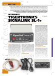
Plug-N-Play Module Installation Instructions
The installation of the of the Plug & Play jumper modules is very simply, but you need to be careful that you don't bend any
of the pins, or they may break off and become stuck inside the SignaLink's socket. You should not have any trouble if you
are just the slightest bit careful, but please note that broken pins and/or any damage to the jumper module or the SignaLink
as a result of broken pins, is not covered under warranty. Also, before installing any jumper module, please verify that you
are installing the correct module for the radio and/or radio cable you will be using (see part numbers shown above!). It is
possible to damage your radio and/or the SignaLink by installing the wrong jumper module, or by installing it backwards, so
please check carefully before proceeding. The header pins used on all jumper modules are small and relatively sharp, so be
careful that you don't stick a finger!
Module Insertion - To install the jumper module, place it lightly on the SignaLink's JP1 jumper socket being careful
to align the notch on the jumper module (white board outline) with the notch on the SignaLink's circuit board
(white colored outline around the JP1 jumper socket). Carefully look at each pin to make sure that all pins are
centered in the socket holes, and then gently press down evenly on the module until it is seated securely in the
socket. Be careful not to press on any jumper pins that might be mounted on the top of the jumper module
(SLMOD13K, SLMOD8RI, etc.).
Special Jumpers - Some jumper modules have one or two special jumpers that may need to be set for your radio
(the PTT Configuration Jumper for the SLMOD13K module is a good example). If this applies to the jumper
module that you are installing, then be sure to see the jumper notes in the appropriate compatible radio links shown
above.
Module Removal - To remove the jumper module, you will need to pull it straight out while being careful not to
bend any pins in the process. Be careful not to drop the module when it pulls loose from the socket! We suggest
gripping the module firmly with a pair of pliers, but any suitable tool can be used. Some customers have removed
the jumper module with a flat blade screwdriver by slowly prying up on both ends a little at a time until it is
out. This is ok ONLY if you lift each end up just the slightest bit (going back and forth from one end to another) so
that the pins are not bent in the process. If you remove the module this way, you need to go very slow and be sure
that you don't lift too much on one end, or put pressure on any of the parts that are mounted on the SignaLink's
circuit board.
NOTE: Each jumper module is carefully inspected before being packaged and shipped to insure that all pins are straight and
the module is in perfect mechanical condition. We use only high quality gold-plated pin strip header, and the header is
designed specifically to plug into the machined socket on the SignaLink circuit board repeatedly. However, it is important
that the pins do not become bent during installation or removal of the module, or they may break and become lodged in the
SignaLink's socket. This is NOT covered under warranty and you would need to return the SignaLink to the factory to have
the socket replaced, as well as purchase a new jumper module.
DX Engineering 2013
1200 Southeast Ave., Tallmadge, OH 44278 USA
Phone: (800) 777-0703 ∙ Tech Support and International: (330) 572-3200
Fax: (330) 572-3279 ∙ E-mail: [email protected]
© 1996-2013 Tigertronics. All Rights Reserved , BayPac, SignaLink, and TigerTrak are trademarks of Tigertronics
All other trademarks are the property of their respective owners
Specifications subject to change without notice