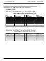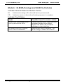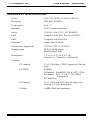
1
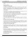
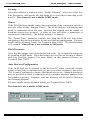
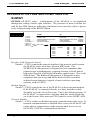
TM
SLM SiteLync
Network Modem
User Guide # S2-60898-100
68-11502-100
CTI Products, Inc.
SLM SiteLync
TM
User Guide
Radio Frequency Emissions and Immunity
This equipment generates, uses, and can radiate radio frequency energy and, if not installed and used in accordance with
the instruction manual, may cause harmful interference to radio communications. Operation of this equipment in a
residential area is likely to cause harmful interference in which case the user will be required to correct the interference at
his own expense. Changes or modifications to this unit not expressly approved by the party responsible for compliance
could void the user’s authority to operate the equipment. Limits specified in the standards listed below are designed to
provide reasonable protection against harmful interference when the equipment is operated in a commercial environment.
UNITED STATES: This equipment has been tested and found to comply with the limits for a Class A digital device,
pursuant to Part 15 of the FCC Rules.
CANADA: This Class A digital apparatus complies with Canadian ICES-003.
Cet appareil numérique de la classe A est conforme a la norme NMB-003 du Canada.
EUROPE: This equipment has been tested and found to conform with the following standards: EN60950, EN55022, and
EN55024.
FCC Notices:
1.
2.
3.
4.
The Federal Communications Commission (FCC) has established Rules which permit this device to be directly
connected to the telephone network. Standardized jacks are used for these connections. This equipment should not
be used on party lines or coin lines.
If this device is malfunctioning, it may also be causing harm to the telephone network; this device should be
disconnected until the source of the problem can be determined and until repair has been made. If this is not done,
the telephone company may temporarily disconnect service.
The telephone company may make changes in its technical operations and procedures; if such changes affect the
compatibility or use of this device, the telephone company is required to give adequate notice of the changes. You
will be advised of your right to file a complaint with the FCC.
If the telephone company requests information on what equipment is connected to their lines, inform them of:
a.
The telephone number this unit is connected to
c. The USOC jack required
b.
The ringer equivalence number
d. The FCC Registration Number
Items ‘b’ and ‘d’ are indicated on the label.
The Ringer Equivalence Number (REN) is used to determine how many devices can be connected to your telephone
line. In most areas, the sum of the RENs of all devices on any one line should not exceed five (5.0). If too many
devices are attached, they may not ring properly.
CAUTIONS:
- Never install telephone wiring during a lightning storm.
- Never install telephone jacks in wet locations unless the jack is specifically designed for wet locations.
- Never touch uninsulated telephone wiring or terminals unless the telephone line has been disconnected at the network
interface.
- Use caution when installing or modifying telephone lines.
Information contained in this document is subject to change without notice and does not represent a
commitment on the part of CTI Products, Inc.
No part of this manual may be reproduced or transmitted in any form or by any means, electronic or
mechanical, including photocopying and recording, for any purpose without the written permission of
CTI Products, Inc.
This manual describes products which include copyrighted CTI Products, Inc. computer programs in
semiconductor memory. CTI Products, Inc. reserves all rights for these programs, including the
exclusive right to copy or reproduce the copyrighted computer programs in any form. No copyrighted
computer program contained in products described in this manual may be copied, reproduced,
decompiled, disassembled, or reversed engineered in any manner without express written permission
of CTI Products, Inc. The purchase of products from CTI Products, Inc. shall not be deemed to grant
either directly or by implication, estoppel, or otherwise, any license under the
copyrights, patents, or patent applications of CTI Products, Inc., except for the normal non-exclusive,
royalty fee license to use that arises by operation of law in the sale of the product.
Copyright (c) 2000 CTI Products, Inc. All rights reserved
SLM SiteLync, SLM/IM, SLM/IS, SLM/CL, SLM/AY and WON are trademarks of CTI Products,
Inc. Echelon, LON, LONWORKS, LONTALK, and Neuron are U.S. registered trademarks of Echelon
Corporation.
CTI Products, Inc.
SLM SiteLync
TM
User Guide
TABLE OF CONTENTS
INTRODUCTION..................................................................................................1
LONWORKS/TELECOM CONNECTIVITY DEVICE ......................................................1
FRONT PANEL .......................................................................................................4
SETUP AND OPERATION...................................................................................6
STEP 1. INSTALLING THE SOFTWARE DRIVERS........................................................6
STEP 2. MOUNTING THE SLM SITELYNC ...............................................................6
STEP 3. MAKING ELECTRICAL CONNECTIONS .........................................................7
STEP 4. CONFIGURING THE SLM SITELYNC ...........................................................7
STEP 5. CONFIGURING HOST PC ............................................................................9
APPENDIX........................................................................................................... 10
APPENDIX A. SLTALINK MANAGER AND NSI MODE ........................................... 10
APPENDIX B. MIP MODE USING THE DOS DRIVER............................................... 13
APPENDIX C. SLM/CONFIG UTILITY .................................................................... 15
APPENDIX D. OPTION SWITCH SETTINGS FOR SLM/AY ..................................... 19
APPENDIX E. EIA-232 (SETUP OR HOST) CONNECTIONS ....................................... 21
APPENDIX F. TROUBLESHOOTING ........................................................................ 22
APPENDIX G. ORDERING CODE ............................................................................ 24
APPENDIX H. SPECIFICATIONS ............................................................................. 26
CTI Products, Inc.
SLM SiteLync
TM
User Guide
Standard Limited Hardware Warranty
LIMITED WARRANTY. Equipment manufactured by CTI Products, Inc. is warranted to be free from
defects in material and workmanship for a period of ONE (1) YEAR from date of shipment to original
purchaser. Under this warranty, our obligation is limited to repairing or replacing any equipment proved to
be defective by our inspection within one year of sale to the original purchaser. This warranty shall not
apply to equipment which has been repaired outside our plant in any way, so as to, in the judgment of CTI
Products, Inc. affect its stability or reliability, nor which has been operated in a manner exceeding its
specifications, nor which has been altered, defaced, or damaged by lightning.
CUSTOMER REMEDIES. In the event of a defect, malfunction, or failure to conform to specifications
established by the seller during the period shown, the customer shall call CTI Products, Inc. to obtain a
Return Authorization Number and return the product or module, shipping and insurance prepaid. CTI
Products, Inc., will then at its option, either repair or replace the product or module and return it, shipping
prepaid, or refund the purchase price thereof. On-site labor at the purchaser's location is not included in
this warranty.
EQUIPMENT NOT MANUFACTURED BY CTI Products, Inc. Equipment not manufactured by CTI
Products, Inc. is excluded from this warranty, but is subject to the warranty provided by its manufacturer, a
copy of which will be supplied to you upon specific written request.
NO OTHER WARRANTIES. The foregoing constitutes the sole and exclusive remedy of the buyer and
exclusive liability of CTI Products, Inc., AND IS IN LIEU OF ANY AND ALL OTHER WARRANTIES
EXPRESSED OR IMPLIED OR STATUTORY AS TO MERCHANTABILITY, FITNESS FOR
PURPOSE SOLD, DESCRIPTION, QUALITY, PRODUCTIVENESS OR ANY OTHER MATTER.
NO LIABILITY FOR CONSEQUENTIAL DAMAGES. WITHOUT LIMITING THE FOREGOING,
IN NO EVENT SHALL CTI PRODUCTS, INC. OR ITS SUPPLIERS BE LIABLE FOR ANY
DAMAGES WHATSOEVER (INCLUDING, WITHOUT LIMITATION, SPECIAL, INCIDENTAL OR
CONSEQUENTIAL DAMAGES OR FOR LOSS OF BUSINESS PROFITS, BUSINESS
INTERRUPTION, LOSS OF BUSINESS INFORMATION, OR OTHER PECUNIARY LOSS) ARISING
OUT OF THE USE OF OR INABILITY TO USE CTI PRODUCTS, INC. EQUIPMENT BY
PURCHASER OR OTHER THIRD PARTY, WHETHER UNDER THEORY OF CONTRACT, TORT
(INCLUDING NEGLIGENCE), INDEMNITY, PRODUCT LIABILITY OR OTHERWISE, EVEN IF CTI
PRODUCTS, INC. HAS BEEN ADVISED OF THE POSSIBILITY OF SUCH DAMAGES OR LOSSES.
IN NO EVENT SHALL CTI PRODUCTS, INC.’S, LIABILITY EXCEED THE TOTAL AMOUNT PAID
BY PURCHASER FOR THE EQUIPMENT GIVING RISE TO SUCH LIABILITY.
Location:
CTI Products, Inc
1211 West Sharon Road
Cincinnati, OH 45240 USA
Phone:
+1.513.595.5900
Fax:
+1.513.595.5983
Web:
www.ctiproducts.com
E-mail, Sales:
Technical Support:
[email protected]
[email protected]
CTI Products, Inc.
SLM SiteLync
TM
User Guide
INTRODUCTION
LONWORKS/TELECOM CONNECTIVITY DEVICE
The SLM SiteLync network modem is an integrated package consisting of a
LonTalk adapter and Telco interface, allowing communications with distant
LonWorks networks using telecommunications media. Its non-router based
design provides maximum connectivity value at minimum levels of installation
and operation cost. It can replace older solutions using multiple units that have
non-standard mounting and power requirements.
LonTalk Adapter
The integral LonTalk Adapter provides Network Services Interface (NSI mode)
or Network Interface functionality (MIP mode). It allows any host to implement
the upper layers of the LonWorks protocol, so applications on the host can send
and receive network variable updates and explicit messages, as well as poll
network variables. The SLM SiteLync network modem must be ordered for use
in either NSI mode or MIP mode. It is not easily field changeable since a factory
configuration of the hardware determines the operating mode. It is available with
either FTT-10A, TPT/XF-78, or TPT/XF-1250 LonWorks network transceiver.
Telco Interface
When ordered with one of the integral telephone service interfaces, the SLM
SiteLync network modem provides the means to connect distant LonWorks
networks using analog (PSTN), digital (ISDN), or cellular channels.
The internal analog modem options in the SLM SiteLync network modem use
proven V.34 terbo modulation, transferring data at 33,600 bits per second. Dialup as well as 2-wire leased lines (for North America only) are supported. The
internal ISDN modem (for Europe only) can connect at 64 Kbps using the S/T
interface. The internal cellular modem uses the AMPS protocol (for North
America only) at data rates up to 4800 bps.
Power Supply
Internal power supply options are available for 10-35VAC/DC or 100-240VAC.
This supplies all necessary power for the SLM unit.
Introduction
1
CTI Products, Inc.
SLM SiteLync
TM
User Guide
Typical Applications
Figure 1 shows a typical monitor and control application with the SLM/IM
SiteLync network modem being used to connect LonWorks networks to a remote
host PC through analog dial-up lines.
LonWorks
Nodes
Host PC
SLM-IM
PSTN
EIA-232
SLM-IM
Standard
Modem
SLM-IM
Figure 1. Typical Remote Monitor and Control Application using PSTN
Lines
Typical applications include monitoring and control of LonWorks devices
utilizing analog, ISDN, and Cell telephone services. By incorporating SLM
SiteLync network modems into the network, applications can be implemented on
a host that is located remotely from the LonWorks network.
Figure 2 shows the SLM/IS (ISDN) SiteLync being used to connect LonWorks
networks to a remote host PC through ISDN lines.
LonWorks
Nodes
Host PC
SLM-IS
ISDN
SLM-IS
Standard
EIA-232 ISDN Modem
SLM-IS
Figure 2. SLM/IS Connecting Networks using ISDN Lines
Introduction
2
CTI Products, Inc.
SLM SiteLync
TM
User Guide
Figure 3 shows the SLM/CL SiteLync being used to connect a LonWorks
network to a remote host PC through a cellular channel. An auxiliary connector
is provided to allow a wired connection to the PSTN. This can be used as a
backup channel when the wireless channel is not available.
Backup Channel
LonWorks
Nodes
Host PC
SLM-CL
PSTN
EIA-232
Standard
Modem
Cell Site
Figure 3. SLM/CL Connecting Networks using a Cellular Channel
Figure 4 shows the SLM/AY SiteLync being used to connect LonWorks
networks to a remote host PC through T1 or E1 channels. This configuration
may also be used with other high speed serial transmission media such as digital
microwave.
LonWorks
Nodes
Host PC
EIA-232
CSU/DSU
T1, E1
or other
High
Speed
Channel
CSU/DSU
SLM-AY
CSU/DSU
SLM-AY
CSU/DSU
SLM-AY
Figure 4. SLM/AY Connecting Networks using a High Speed Channels
Introduction
3
CTI Products, Inc.
SLM SiteLync
TM
User Guide
The SLM/AY SiteLync can also operate as a serial (EIA-232) LonWorks
Network Services Interface (NSI) or Network Interface (NI) as shown in Figure
5.
Host PC
LonWorks
Nodes
SLM-AY
EIA-232
Figure 5. SLM/AY used as a LonWorks NSI or NI
FRONT PANEL
All operator controls and connectors are accessible from the front panel. Figure 6
shows the front panel of the SLM/IM model. Other models are similar in
appearance.
The SLM/AY (no modem) does not contain the “RUN/CFG” switch, rather it has
an 8 position OPTION DIP switch. See APPENDIX D for descriptions of these
switch functions.
Figure 6. SLM/IM Network Modem Front Panel
Introduction
4
CTI Products, Inc.
SLM SiteLync
TM
User Guide
CONNECTORS
NET
LonWorks network, polarity insensitive
L1, L2
Input power, DC is polarity insensitive
SETUP
EIA-232 port for configuration. In RUN mode, data from the modem is
also transmitted on this port for diagnostic purposes.
HOST
EIA-232 HOST port for SLM/AY.
PSTN
Telephone line connection for SLM/IM and SLM/CL.
ISDN
S/T connection for SLM/IS.
CELL
Cell phone connection for SLM/CL
INDICATORS
TX
Indicates packet is transmitted from the LonTalk adapter.
RX
Indicates packet is received by the LonTalk adapter.
RI
Indicates incoming call is detected but not yet answered.
LNK
Indicates cable is connected to ISDN termination device(SLM/IS only).
B
Indicates a call has been established with another ISDN modem (SLM/IS
only).
CD
SLM/IM: Indicates carrier is detected and training sequence / protocol
negotiation completed.
SLM/IS: Indicates a call has been established AND the B channel
protocol negotiation has been completed.
SERVICE
ON :
Power-up initialization in progress (approximately 6 seconds).
Blinking : LonTalk adapter is unconfigured.
PWR
Indicates input power is present.
SWITCHES
SERVICE
Initiates Service pin message from LonTalk adapter.
RESET
Initializes SLM hardware, causes all switches to be read.
RUN/CFG
RUN:
CFG:
OPTION
Sets various options for SLM/AY only. See Appendix D for details.
AUX
(Internal switch located in front of the NET connector), normally left in the
OFF (left, away from the PWR connector) position. In the ON (right,
toward the PWR connector) position, the SETUP connector is internally
connected to the modem for those rare cases when the modem must be
accessed directly for diagnostic purposes.
Introduction
Connects modem to LonTalk Adapter.
Connects LonTalk Adapter to SETUP port.
5
CTI Products, Inc.
SLM SiteLync
TM
User Guide
SETUP AND OPERATION
STEP 1. INSTALLING THE SOFTWARE DRIVERS
Drivers must be installed on the Host PC to allow communications with an SLM
SiteLync module. Even if these device drivers have previously been installed on
the host PC for use with some other type of network interface, it is recommended
that the following procedure be used to ensure the correct installation of the
drivers and the SLM/Config utility. To install all necessary drivers and software,
perform the following steps:
a. Close all open programs.
b. Insert the SLM SiteLync installation disk 1 into the PC.
c. Click the Start button on the Windows task bar and select the run
command.
d. When prompted for a program name, enter the following:
A:\SETUP.EXE
e. Follow the prompts in the setup process. The following software will be
installed:
• If NSI mode is selected, SLTALink Manager and a virtual DOS
driver for the SLM/Config utility, or
• If MIP mode is selected, SLTA DOS device driver for MIP
applications and the SLM/Config utility.
• SLM/Config utility (slm.exe) and associated .dll and .vbx files.
f. At the prompt to restart the PC, remove the SLM SiteLync installation
disk and restart the computer.
g. To install drivers for both NSI and MIP modes, simply run the installation
program twice.
STEP 2. MOUNTING THE SLM SITELYNC
The SLM SiteLync network modem must be mounted using a standard DIN rail
per EN50022 inside an approved fire enclosure as defined in UL1950. The
length of DIN rail channel required to properly mount the SLM is 3.5 inches.
There are no user-serviceable components inside the SLM unit and it should not
be disassembled. Should the unit require repair, it must be returned to CTI
Products, Inc.
Setup and Operation
6
CTI Products, Inc.
SLM SiteLync
TM
User Guide
STEP 3. MAKING ELECTRICAL CONNECTIONS
LonWorks Network Connection (NET)
Connect the LonWorks twisted pair channel to the SLM module via the 2
terminal NET connector. This connection is non-polarity sensitive.
Telephone Line Connection (PSTN, ISDN, or CELL)
Connect the telephone service line to the PSTN (for SLM/IM), ISDN (for
SLM/IS), or CELL (for SLM/CL) connector. An RJ11 is provided on the
SLM/IM and SLM/CL models. An RJ45 is provided on the SLM/IS model.
Input Power Connection
Power input is applied to the SLM module via the 3 terminal connector. The
terminals labeled ‘L1’ and ‘L2’ are used for the mains input. SLM units with
power input rating of 10-35 volts AC/DC are polarity insensitive. The terminal
marked with the ground symbol should be connected to protective earth ground.
For SLM units with power input rating of 100-240 VAC that are permanently
connected, a readily accessible disconnect device must be incorporated in the
fixed wiring. For those connected with a pluggable device, the socket-outlet
must be installed near the SLM and must be easily accessible.
Apply power to the SLM SiteLync network modem only after all other
connections have been made.
After power is applied, the PWR indicator should come on. Also, the SERVICE
indicator should come on for approximately 6 seconds. After the SERVICE
indicator goes off, the SLM is ready for use.
STEP 4. CONFIGURING THE SLM SITELYNC
Most typical applications (where a host computer is used to dial into multiple
remote sites containing SLM/IM, SLM/IS, or SLM/CL modules) can make use of
the factory default configuration of the SLM SiteLync (as follows):
•
All models :
RUN mode
•
All models :
Auto-answer enabled
•
•
•
All models :
Auto-Dial-Out mode : disabled
SLM/IM (EU) : Country code = Europe
SLM/IS (EU) : D channel protocol = Euro-ISDN (DSS1)
B channel protocol = X.75
Setup and Operation
7
CTI Products, Inc.
SLM SiteLync
TM
User Guide
User configuration of SLM SiteLync network modems will only be needed in the
following situations :
•
An SLM/IM used in Europe, where the default country code of
“Europe” does not function properly (see “Modem Options” in
APPENDIX C).
•
An SLM/IS requiring other than the Euro-ISDN (DSS1) D channel
protocol and the X.75 B channel protocol (see “Modem Options” in
APPENDIX C).
•
An SLM/IM, SLM/IS, or SLM/CL that will make use of the Auto-DialOut function (see Auto-Dial-Out configuration in Appendix C).
•
SLM/AY units needing switch settings other than factory default (See
APPENDIX D).
Will Configuration be
Required?
ý
þ
?
If NO, and the SLM will be used
with its factory default settings,
skip to STEP 5. The SLM is ready
to function in a network.
To learn more about
Auto-Dial-Out Mode,
Country Codes, and
ISDN protocols, see
APPENDIX C.
If YES, see APPENDIX D for the
SLM/AY, or User Configuration
of the SLM SiteLync (below) for
all other models.
User Configuration of the SLM SiteLync
Note: Be sure to shut down any host application (i.e. LonMaker, Nodeutil, etc.)
before attempting to run the SLM/Config utility.
If configuration of the SLM SiteLync is necessary, follow these steps:
a. Connect a standard (straight-through) serial cable from the proper serial
port on the PC containing the software installed in Step 1 to the SETUP
connector on the SLM SiteLync network modem. See APPENDIX E for
connection details.
b. Set the RUN/CFG switch to the CFG (CONFIGURE) position.
c. Connect power to the SLM SiteLync network modem, or press RESET if
the unit is already powered.
d. If using the SLM SiteLync in MIP mode, skip to Step e. If using the SLM
SiteLync in NSI mode, use SLTALink Manager to establish a “Local
Link” with the SLM SiteLync module. Characteristics such as host PC
Setup and Operation
8
CTI Products, Inc.
SLM SiteLync
TM
User Guide
port and baud rate can be specified. See “Establishing a New Local Link”
in APPENDIX A for details.
e. Run the SLM/Config utility (slm.exe) to customize the SLM SiteLync
module for the application. Be sure to set the proper LON Channel from
the LON Setup menu. Characteristics such as modem properties (ie,
county code, auto-dial mode, dial directories), security callback, hang-up
timer, and auto-dial-out can be specified. The SLM/Config utility is
similar to the Configure SLTA selection in the Devices menu of SLTALink
Manager. Although either program may be used to configure the SLM
SiteLync (in NSI mode), the SLM/Config utility eases the task of
determining the modem initialization string, allows the configuration
choices to be saved to and retrieved from a disk file, and can be used with
the SLM SiteLync in either NSI or MIP mode. See APPENDIX C for
details about the SLM/Config utility.
f. When configuration is complete, set the RUN/CFG switch to the RUN
position, and press the RESET button.
g. Remove the serial cable from the SETUP connector on the SLM SiteLync.
STEP 5. CONFIGURING HOST PC
If the SLM SiteLync is being used in MIP mode, no other configuration of the
DOS and 16 bit Windows drivers installed in Step 1 is required. The SLM is
ready to be used with the Host Application. See Appendix B for details on
dialing into a remote SLM SiteLync from the Host PC.
If the SLM SiteLync is being used in NSI mode, a “link” must be established
between the PC and the SLM SiteLync before a host application can be executed.
A link may be either “local”, where the PC is directly connected to the SLM via
an RS232 cable, or “remote”, where the PC (with an internal or external modem)
is connected to the SLM via a telephone or cellular channel.
To establish a new local or remote link with an SLM SiteLync in NSI mode using
SLTALink Manager, see “Establishing and New Local Link” or “Establishing a
in APPENDIX A.
Information in APPENDIX A for remote links applies to the most common usage
of the SLM SiteLync where the PC “dials-in to” remote SLM SiteLync sites. For
information on the more advanced usage where the SLM SiteLync in NSI mode
automatically dials-in to the PC, please refer to Technical Note TN031.
Setup and Operation
9
CTI Products, Inc.
SLM SiteLync
TM
User Guide
APPENDIX
APPENDIX A. SLTALINK MANAGER AND NSI MODE
Host Applications using the LNS platform (such as LonMaker for Windows and
Windows DDE Server) require the SLM SiteLync to be used in NSI mode, along
with the SLTALink Manager. The SLTALink Manager provides a Windows 32bit driver and a user interface for controlling the connection through an SLM
SiteLync network modem in NSI mode and for diagnosing connection problems.
It can monitor a modem line, answer an incoming call, associate the incoming
call’s SLM SiteLync (and hence its network) with a LonTalk node, and then
launch a pre-determined application for that particular network or SLM SiteLync.
Parameters such as local/remote connection, dialing preferences (area code,
access number, tone/pulse dialing, calling card dialing), monitoring for dial-in,
and link associations (to an application during dial-in) can be altered. The
SLTALink Manager enables a LonWorks network to establish a connection to a
host PC based on an event that occurs in the remote network (such as an alarm
condition). Refer to Technical Note TN031 to learn more about these advanced
SLM SiteLync and SLTALink Manager features.
DOS and 16-bit Windows LonManager API applications (such as Lonmaker for
DOS and Nodeutil) can make use of the SLM SiteLync in NSI mode via the
SLTALink Manager driver through the ldvvdd.sys (Windows 9x) or pcltdos.sys
(Windows NT) virtual device drivers. If the NSI mode driver installation was
performed as described in STEP 1 of the “SETUP AND OPERATION” section, the
driver was loaded onto the host PC, and a device driver line was added to the
config.sys file similar to one of the following:
Windows 9x (config.sys file)
device=c:\progra~1\ctipro~1\slm\ldvvdd.sys /D1 /V”LonSLTA”
Windows NT (config.nt file)
device = %systemroot%\system32\pcltdos.sys /D1
Figure 7 shows a typical host PC configuration when using SLTALink Manager
in an LNS application. The host PC configuration would be the same if
connected to a local SLTA SiteLync used as a Network Services Interface in NSI
mode.
Appendix A. SLTALink Manager and NSI Mode
10
CTI Products, Inc.
SLM SiteLync
TM
User Guide
Host PC
Host Application
LNS Software
SLTALink Manager
and
LDVVDD.SYS
Network Driver
EIA-232
Interface
Standard
Modem
LonWorks
Nodes
PSTN
SLM-IM
Figure 7. NSI Mode with Host PC using SLTALink Manager
Establishing a New Local Link
Use this procedure when the SLM SiteLync SETUP OR HOST port is connected
directly to the PC COM port via an RS232 cable. For the SLM/AY, be sure that
OPTION switch position 2 is in the UP position. For all other models, be sure
that the RUN/CFG switch is in the CFG position. Following any change to
switch settings, be sure to power cycle or RESET the SLM SiteLync.
To establish a new local link with an SLM SiteLync using SLTALink Manager,
use the following steps:
a. From the Link menu, choose New.
b. In the “Link Description” window, specify a Name, click the Local button,
then click the Next button.
c. In the “Comm Port” window, specify the serial port to which the SLM
SiteLync will be connected, select a baud rate of 57600, then click the Next
button.
d. In the “Link Properties” window, accept the default field values by clicking
the Finish button.
e. From the Link menu, choose Select and select the link just configured from
the list .
f. Manually connect to the local SLM by clicking the “Link” button shown
here.
Connection status will be indicated in the main window. If
successful, the “Remote Identifier” will be shown.
Appendix A. SLTALink Manager and NSI Mode
11
CTI Products, Inc.
SLM SiteLync
TM
User Guide
Establishing a New Remote Link
Use this procedure when using an internal or external modem on the PC to dial in
to a remote SLM SiteLync. For the SLM/AY, be sure that OPTION switch
position 2 is in the DOWN position. For all other models, be sure that the
RUN/CFG switch is in the RUN position. Following any change to switch
settings, be sure to power cycle or RESET the SLM SiteLync.
The modem connected to the host PC must first be installed using Modems
function in the Windows Control Panel. Be sure the “Modem Maximum Speed”
parameter in the “Standard Modem Properties” window is set to 57600 baud.
Once the PC modem is installed to Windows, establish a new remote link with an
SLM SiteLync using SLTALink Manager by using the following steps:
a.
b.
c.
d.
e.
f.
g.
h.
i.
From the Line menu, choose Dialing Preferences. Click the Dialing Properties
button to bring up the “Dialing Properties window. Ensure that information
is correct for the location of the host PC.
From the Link menu, choose New.
In the “Link Description” window, specify a Name, click the Remote
button, then click the Next button.
In the “Dialing Address” window, specify the phone number (“Phone
-window) and select the modem to be used (“Connect Using”
sub-window).
If additional modem setup commands are needed for the modem attached to
the host PC (such as a command to set the B Channel protocol of an ISDN
modem to match the protocol selected for the SLM SiteLync), they can be
entered as follows :
•
In the “Connect Using” window, click the Configure Line button to
access modem parameters.
•
From the Connection tab, click the Advanced… button, then enter
required command string (starting with ‘AT’) in the “Extra
x.
• Click the OK button to accept the new advanced settings.
• Click the OK button to return to the Dialing Address window.
Click the Next button
In the “Link Properties” window, accept the default parameters by clicking
the Finish button.
From the Link menu, choose Select and select the link just configured from
the list.
Manually connect to the remote SLM by clicking the “Link” button shown
here.
Connection status will be indicated in the main window. If
successful, the “Remote Identifier” will be shown.
Appendix A. SLTALink Manager and NSI Mode
12
CTI Products, Inc.
SLM SiteLync
TM
User Guide
APPENDIX B. MIP MODE USING THE DOS DRIVER
LDVSLTA.SYS is the driver used for non-LNS applications running on a DOS
or Windows 9x platform involving the SLM SiteLync network modem in MIP
mode. This driver will not function on Windows NT. If the MIP mode driver
installation was performed as described in STEP 1 of the “SETUP AND
OPERATION” section, the MIP mode driver (ldvslta.sys) was loaded onto the host
PC. In addition, a device driver was added to config.sys similar to the following:
device=c:\progra~1\ctipro~1\slm\ldvslta.sys /B57600 /P1
/D1
Figure 8 shows the host PC configuration when MIP mode is used.
Host PC
Host Application
LDVSLTA.SYS
Network Driver
EIA-232
Interface
Standard
Modem
LonWorks
Nodes
PSTN
SLM-IM
Figure 8. MIP Mode with Host PC using LDVSLTA.SYS Device Driver
No configuration of the ldvslta.sys driver is required or supported.
The SLM SiteLync in MIP mode can be connected to the PC either locally via an
RS232 cable, or remotely via a modem at the PC. Set the SLM SiteLync
switches as follows, depending on the choice of local or remote connection:
SLM Model
SLM/AY
SLM/AY
All Others
All Others
Local / Remote
Local
Remote
Local
Remote
Switch Setting
OPTION 2 : UP
OPTION 2 : DOWN
RUN/CFG : CFG
RUN/CFG : RUN
Following any change to switch settings, be sure to power cycle or RESET the
SLM SiteLync.
Dialing from the PC to a remote SLM SiteLync can be performed using the DOS
program HCU.EXE (installed in Step 1 of the Setup and Operation section) by
Appendix B. MIP Mode Using the DOS Device Driver
13
CTI Products, Inc.
SLM SiteLync
TM
User Guide
typing : HCU [-DLONn] ATDTddddddd!<CR>, where n is the LON device number
and dddddd is the number to be dialed, followed by an exclamation point.
Appendix B. MIP Mode Using the DOS Device Driver
14
CTI Products, Inc.
SLM SiteLync
TM
User Guide
APPENDIX C. SLM/CONFIG UTILITY
The SLM/Config utility (slm.exe) is a tool to customize the SLM SiteLync
module for an application. Characteristics such as modem properties (ie, county
code, auto-dial mode, dial directories), security callback, hang-up timer, and
auto-dial-out can be specified. The SLM/Config utility is very similar to the
Configure SLTA selection in the Devices menu of SLTALink Manager. Although
either program may be used to configure the SLM SiteLync (in NSI mode), the
SLM/Config utility eases the task of determining the modem initialization string,
allows the configuration choices to be saved to and retrieved from a disk file, and
can be used with the SLM SiteLync in either NSI or MIP mode.
The software driver installation procedure (described in Step 1 of the “Setup and
Operation” section) will place the SLM/Config utility (slm.exe) in the following
directory unless otherwise specified:
C:\Program Files\CTI Products Inc\SLM
If using the SLM SiteLync in NSI mode (local or remote), the link to the SLM
must already be established using SLTA Link Manager before proceeding, see
Appendix A.
Any LonWorks host application (LNS, DOS, or Windows) using the SLM
SiteLync to be configured must be shut down before proceeding. Only one
application using a particular SLM SiteLync (including SLM/Config) may be
running at any one time.
Start the SLM/Config utility by double clicking the file name (slm.exe) in
Windows Explorer. The following startup window will be displayed.
Selecting the LON Channel
From the LON Device menu, select the LON channel assigned to the SLM
SiteLync being configured. Up to two LON channels will appear, one for NSI
mode and one for MIP mode, based on channels selected during installation.
Appendix C. SLM/Config utility
15
CTI Products, Inc.
SLM SiteLync
TM
User Guide
Configuration Using an Existing File
To configure an SLM SiteLync using an existing file that was previously saved
from the SLM/Config utility, select from the File menu : Open File, and select the
file to open. The Modem Setup window will be displayed and parameters may
be viewed or altered. Click on the Apply button to download the parameters to a
connected SLM SiteLync network modem.
Retrieving Configuration from an Existing SLM SiteLync
Parameters may be uploaded from a previously configured SLM SiteLync
network modem using the Upload From Connected SLM item of the File menu.
This feature is available only in NSI mode. Once uploaded, they may be
downloaded to additional SLM SiteLync units or modified and resent back to the
same unit, as described below.
Configuration for a New Application
To configure an SLM SiteLync module for a new application, select New File
from the File menu. Select the appropriate SLM SiteLync model, then select NSI
Mode or MIP Mode. The Modem Setup window will be displayed as follows (for
example, the European Union (EU) compatible analog modem, NSI mode) :
Specify the parameters for the following features based on system requirements.
After all parameters have been correctly specified, click on the Apply button to
download the parameters to the connected SLM SiteLync network modem.
Appendix C. SLM/Config utility
16
CTI Products, Inc.
SLM SiteLync
Parameters may also be saved to a file using the
menu.
TM
Save File As
User Guide
item of the
File
Modem Options
Country (EU Analog Only)
European Union compatible modems allow a specification to enable country
specific line requirements. Test the SLM SiteLync first using the “Europe”
selection. If the connection is not satisfactory, select the actual country of
location from the drop-down list. Europe is the default selection.
Auto Answer
If the SLM Network Modem must automatically answer incoming calls, select
“Auto Answer”. Auto Answer enabled is the default state.
Answer/Originate Mode (Analog Leased Lines Only)
In leased line operation, it is suggested that the SLM SiteLync network modem
operate in Answer Mode. Answer Mode is the default state. The modem at the
host PC should be placed in Originate Mode.
Pulse Dial (Analog Dial-Up Only)
If the SLM Network Modem must use pulse dialing (as opposed to the more
common tone dialing), select “Pulse Dial”. Pulse Dial disabled is the default
state.
B Channel Protocol (ISDN Only)
The Bearer (B) Channel is used for transmitting data on the ISDN line. A variety
of protocols are used to format the data on the B Channel. Specify the protocol
to match the protocol used in the ISDN modem connected to the host PC to
which the SLM SiteLync will communicate.
D Channel Protocol (ISDN Only)
The Delta (D) Channel is used for call supervision and control, and the
activation/deactivation of ISDN features. A variety of protocols are used to
format the data on the D Channel. Specify the protocol required by the ISDN
line provider.
Extra Settings
In some cases, additional initialization commands are needed to configure the
SLM Network Modem to customer specific requirements. When specified in this
text box, these characters are appended to the dial string, and appear in the
“Resulting Modem Settings” box. Normally, this box should be left blank.
Resulting Modem Settings
This read-only line shows the complete initialization string to be downloaded to
the SLM SiteLync.
Appendix C. SLM/Config utility
17
CTI Products, Inc.
SLM SiteLync
TM
User Guide
Security
If security callback is required, select “Enable Callback”, select one of the five
Dial Directories, and specify the dial string to be used when connecting to the
host PC. This feature is not available in MIP mode.
Timers
If the SLM SiteLync should control the termination of the connection, specify a
non-zero value for the “Hangup Timer”. The SLM SiteLync will hang-up and
break a connection when the time specified has elapsed and no uplink or
downlink activity has occurred. A value of zero will allow a connection to
remain active indefinitely. The default setting is 15 minutes.
The “Guard Time” parameter controls how long the SLM will wait before
attempting to dial the next number for the auto dial-out configuration. For more
details on this advanced feature, see Technical Note TN031. The default setting
is 45 seconds. Guard Time is not available in MIP mode.
Dial Directories
Up to five dial strings can be specified in NSI mode. Up to eight dial strings can
be specified in MIP mode. These dial strings are used for the Security Callback
and Auto Dial-Out features. For more details on this advanced feature, see
Technical Note TN031.
Auto Dial-out Configuration
If the SLM SiteLync is required to dial the host PC when a network variable
update occurs from a connected node (ie, due to an alarm condition), then select
“NV Connect” and specify a range of dial directories to use. Multiple directories
may be specified to allow a connection retry to another directory number if the
first number was busy. Normally, only one directory will be used as shown in
the following diagram.
For more details on this advanced feature, see Technical Note TN031.
This feature is not available in MIP mode.
Appendix C. SLM/Config utility
18
CTI Products, Inc.
SLM SiteLync
TM
User Guide
APPENDIX D. OPTION SWITCH SETTINGS FOR
SLM/AY
OPTION (SLM/AY only): Configuration of the SLM/AY is accomplished
through the setting of these eight switches. The positions of these switches are
read by the SLM firmware following a hardware reset caused by either a power
cycle or the pressing of the RESET button.
1
2
3
4
5
6
7
8
DOWN
UP
1. CFG3 ................. Buffered Link Protocol
ALERT/ACK Link Protocol
2. CFG2 ................. Remote Host
Local Host
3. CFG1 ................. Network Disabled after Reset
Network Enabled after Reset
4. CFG0 ................. 8 Wire Interface
3 Wire Interface
5. AutoBaud ........... Autobaud Enabled
Autobaud Disabled
6. Baud 2
Baud Rate
Switch:
6
7
7. Baud 1
Baud Rate
115200
DN
DN
8. Baud 0
57600
(default)
DN
DN
38400
DN
UP
19200
DN
UP
9600
UP
DN
2400
UP
DN
1200
UP
UP
14400
UP
UP
(default)
(default)
(default)
(default)
(default)
8
DN
UP
DN
UP
DN
UP
DN
UP
Interface Link Protocol Control
Switch 1 / CFG3 controls the network interface link protocol used between
the SLM/AY and a local host, when in MIP mode. The
ALERT/ACK link protocol is designed for host computers that
cannot accept asynchronously occurring streams of serial data at
high speed (typical of DOS and Windows applications). This is the
default state. The Buffered link protocol is designed for host
computers that can accept and buffer back-to-back serial data
without losing characters (typical of most real-time operating
systems, such as UNIX).
Modem Support
Switch 2 / CFG2 controls the use of the SLM/AY with an external modem.
If the SLM/AY is connected directly to a host, then this switch
should be set to the Local Host state. This is the default position. If
the SLM/AY is connected to a modem, then this switch should be
set to the Remote Host state and CFG3 must be set to ALERT/ACK.
Network Disable
Switch 3 / CFG1 enables or disables network communications after reset. If
network communications is disabled after a reset, the SLM/AY will
not be able to communicate on the network until it receives an
niFLUSH_CANCEL command from the host.
Appendix D. OPTION Switch Settings for SLM/AY
19
CTI Products, Inc.
SLM SiteLync
TM
User Guide
EIA-232 (SETUP) Interface
Switch 4 / CFG0 enables either a 3 wire (TxD, RxD, GND) or 8 wire (TxD,
RxD, DCD, DTR, RTS, GND) interface for the EIA-232 SETUP
connector. The default setting is 3 Wire Interface.
Autobaud
Switch 5 enables or disables the automatic selection of baud rate by the
SLM/AY. The recommended setting is Disabled, and should only
be Enabled when a fixed baud setting is not appropriate and when
the SLM/AY is connected to a local host. The Autobaud algorithm
is performed after a power cycle or reset. The default setting is
Disabled.
Baud Rate
Switches 6, 7, and 8 are used to set the serial bit rate. This setting is only
used if Autobaud is disabled. All data are transmitted using 1 start
bit, 8 data bits, no parity bits, and 1 stop bit.
Appendix D. OPTION Switch Settings for SLM/AY
20
CTI Products, Inc.
SLM SiteLync
TM
User Guide
APPENDIX E. EIA-232 (SETUP OR HOST)
CONNECTIONS
Attaching the SLM SiteLync directly to a PC
Table 1. DB-9 to DB-9 Straight Through Cable
PC
Signal Name
DCD
RxD
TxD
DTR
Signal Ground
DSR
RTS
CTS
PC
DB-9 Female
Pin 1
Pin 2
Pin 3
Pin 4
Pin 5
Pin 6
Pin 7
Pin 8
SLM
DB-9 Male
Pin 1
Pin 2
Pin 3
Pin 4
Pin 5
Pin 6
Pin 7
Pin 8
SLM
Signal Name
DCD
RxD
TxD
DTR
Signal Ground
DSR
RTS
CTS
Attaching the SLM/AY to an External Modem
Table 2. DB-25 to DB-9 Null Modem Cable
Modem
Signal Name
RxD
TxD
DCD
DTR & RTS
Signal Ground
Modem
DB-25 Male
Pin 3
Pin 2
Pin 8
Pin 20 & Pin 4
Pin 7
SLM
DB-9 Male
Pin 3
Pin 2
Pin 4
Pin 6
Pin 5
Appendix E. EIA-232 (Setup or Host) Connections
SLM
Signal Name
TxD
RxD
DTR
DSR
Signal Ground
21
CTI Products, Inc.
SLM SiteLync
TM
User Guide
APPENDIX F. TROUBLESHOOTING
Models : ALL
Indicator Normal States for LonTalk Adapter Portion
PWR
SERVICE
Indicates power is applied to the SLM device.
Indicates reset cycle and LonTalk adapter configuration.
Indicator Fault States
Fault
Possible Cause/Corrective Action
PWR is not illuminated
Proper power is not attached to SLM.
Check the power input. If it is correct,
SLM must be returned for
evaluation/repair.
The SLM unit is defective. The unit
must be returned for evaluation/repair.
SERVICE does not illuminate at
power-up or reset or it stays on
for more than 6 to 8 seconds
SERVICE is blinking
The LonTalk adapter is in the
unconfigured state. Commission the
LonTalk adapter with a network
management tool
Model : SLM/IS (ISDN)
Indicator Normal States for Modem Portion
LNK
B
CD
Indicates cable is connected to an ISDN termination device.
Indicates a call has been established with another ISDN modem.
Indicates a call has been established with another ISDN modem and the
B channel protocol negotiation has been completed.
Indicator Fault States
Fault
Possible Cause/Corrective Action
LNK is not illuminated
Check ISDN cable and power to SLM
and ISDN termination device
The wrong number was dialed, or SLM
auto-answer mode is disabled. Enable
auto-answer using SLM/Config.
B channel protocol selection is wrong.
Use SLM/Config to make SLM B
channel protocol match that used by the
ISDN modem connected to the PC.
B is not illuminated,
but call is placed
CD is not illuminated,
but call is placed and B is on.
Appendix F. Troubleshooting
22
CTI Products, Inc.
SLM SiteLync
TM
User Guide
Models : SLM/IM (Analog) and SLM/CL (Cellular)
Indicator Normal States for Modem Portion
RI
CD
Indicates incoming call is detected but not yet answered.
Indicates carrier is detected and training sequence is complete.
Indicator Fault States
Fault
Possible Cause/Corrective Action
RI does not illuminated when a
call is placed to the SLM
Check telephone cable connection and
telephone number being dialed.
Replace the SLM with a standard
telephone to check the line.
Auto-answer mode is disabled. Use
SLM/Config to enable auto-answer.
RI blinks when call is placed,
but CD never illuminates.
Appendix F. Troubleshooting
23
CTI Products, Inc.
SLM SiteLync
TM
User Guide
APPENDIX G. ORDERING CODE
The ordering code of the SLM SiteLync module indicates the installed options.
This ordering code is of the form: SLM/ XX - T I P - M C , where
XX = Phone Line Usage
T
= LonWorks Network Transceiver
I
= LonWorks Interface
P
= Power Input
M = Modem
C
= Cell Cable
(XX) Model Type
The following model types are available, indicating the applicable phone
channel:
IM = Analog Phone Lines
IS = ISDN Phone Lines
CL = Cellular Link
AY = Direct Connect (for use as a local network interface)
(T) LonWorks Network Transceiver
The following LonWorks network transceiver options are available:
A = FTT-10A
B = TPT/XF-78
C = TPT/XF-1250
(I) LonWorks Interface
The following LonWorks Interface options are available:
3 = NSI Mode (for LNS applications)
4 = MIP Mode (for non-LNS applications)
(P) Power Supply
The following Power Supply options are available:
1 = 10 – 35 V AC/DC
2 = 100 – 240 VAC
(M) Modem
The following Modem options are available:
F = Analog Dial-Up for US and Canada
G = Analog Leased Line for US and Canada
H = Analog Dial-Up for European Community (CTR21)
K = ISDN for European Community
L = AMPS for US and Canada
(C) Cell Cable
The following Cell Cable options are available:
4 = Nokia
5 = Motorola MicroTac Elite
X = None
Appendix G. Ordering Code
6 = Motorola StarTac
24
CTI Products, Inc.
SLM SiteLync
TM
User Guide
APPENDIX H. SPECIFICATIONS
Power:
10 to 35VAC/DC, or 100 to 240VAC
Mounting:
DIN Rail, EN50022
Temperature:
0-60 °C
Humidity:
10-95% non-condensing
Safety:
UL1950, CSA C22.2 , EC EN60950
EMI:
Complies with: FCC Part 15, EN55022
EMC:
Complies with EN55024
European:
Carries the CE Mark
Transceivers Supported:
FTT10A, TPT78, TPT1250
Configuration:
SLTA Link Manager,
SLM/Config Utility
Dimensions:
3.5” (w) x 3.0” (h) x 4.2” (d)
90mm (w) x 75mm (h) x 107mm (d)
Telecom:
EU Analog
V.34, 33600 bps, CTR21 Approved, Dial-up
Only
EU ISDN
64 Kbps,
D Channel : EuroISDN, VN-4, NTT, 1TR6
B Channel : X.75, V.110, V.120, HDLC
Transparent
S/T Interface
US Analog
V.34, 33600 bps, FCC Part 68 Approved,
Dial-up or 2-wire Leased-line
Cellular
AMPS, 4800 bps maximum
Appendix H. Specifications
25