1
Microtek ScanWizard Pro
Reference Manual
For Mac OS X
Copyright © 2002 by Microtek International, Inc.
All rights reserved.
Trademarks
Microtek®, AritxTM, and ScanWizardTM Pro are trademarks or registered trademarks of Microtek International
Inc. Adobe® and Acrobat® are registered trademarks of Adobe Systems Incorporated. Macintosh® and Apple®
are registered trademarks of Apple Computer, Inc. Windows® is a registered trademark of Microsoft
Corporation. All other products or name brands are trademarks of their respective holders.
Important
Documents that you scan may be protected under copyright law. The unauthorized use of such documents
could be a violation of the rights of the copyright holder. Microtek bears no responsibility for the
unauthorized use of copyrighted materials.
To obtain optimal results from the Microtek scanning software and user's manual, you should be familiar
with such Windows concepts as pointing, clicking, dragging, and selecting from menus and dialog boxed. If
these things are new to you, refer to your Microsoft Windows User's Guide.
March 2002
Microtek Lab, Inc.
16941 Keegan Avenue
Carson, CA 90746
Main: 310-687-5800
FAX: 310-687-5950
http://www.microtekusa.com
Microtek International, Inc.
6, Industry East Road 3
Science Based Industrial Park
Hsinchu, 30077, Taiwan
TEL: 886-3-5772155
FAX: 886-3-5772598
http://www.microtek.com
ii
Microtek Europe B.V.
Klompenmaker Str. 76
3194DE Hoogvliet-RT
The Netherlands
TEL: +31-10-242-5688
FAX: +31-10-242-5699
http://www.microtekeurope.com
Contents
Introduction ................................................................................................. 1
ScanWizard Pro for Mac OS X: The Interface ................................................................ 2
Launching ScanWizard Pro ............................................................................................. 3
Exiting ScanWizard Pro ................................................................................................... 3
The Preview Window .................................................................................. 4
Elements of the Preview window .................................................................................... 4
The File Menu .................................................................................................................. 6
The Context Concept ................................................................................................ 7
New ScanWizard Context ......................................................................................... 8
Load ScanWizard Context ........................................................................................ 8
Save ScanWizard Context As ................................................................................... 8
SnapTrans Templates ................................................................................................ 9
Show Current Context Path .................................................................................... 10
Quit ......................................................................................................................... 10
The Scanner Menu ......................................................................................................... 11
Scanner Model ........................................................................................................ 12
Current Scanner Info ............................................................................................... 12
Scanner Probe ......................................................................................................... 12
Scanner Driver Manager ......................................................................................... 13
Scanner Controls ..................................................................................................... 15
The View Menu .............................................................................................................. 16
Overview Image and Prescan Image ...................................................................... 17
Resize Window to Fit .............................................................................................. 19
Bring Settings Window to Front ............................................................................. 20
Show / Hide ... Window commands ....................................................................... 20
Show / Hide Low & High Value Markers .............................................................. 20
About ...................................................................................................................... 20
The Preferences Menu ................................................................................................... 21
Scan Material .......................................................................................................... 22
Color Matching Setup ............................................................................................. 23
White/Black Points Setup ....................................................................................... 26
Auto Clipping .................................................................................................. 26
Output Levels .................................................................................................. 27
High and Low Value Markers .......................................................................... 27
Cursor Auxiliary Lines ........................................................................................... 28
Overview Setup ...................................................................................................... 29
Prescan Setup .......................................................................................................... 32
iii
Invert ....................................................................................................................... 34
Retain Scan Module after Scan ............................................................................... 35
More... ..................................................................................................................... 36
Smoked Glass Background .............................................................................. 37
Working Color Space ....................................................................................... 38
Scan Quality .................................................................................................... 38
Interpolation Mode .......................................................................................... 38
Scratch Directory ............................................................................................. 39
The Correction Menu ..................................................................................................... 40
The Help Menu .............................................................................................................. 40
The Toolbar .................................................................................................................... 41
Scan Frame tool ...................................................................................................... 42
Zoom tool ................................................................................................................ 43
Move tool ................................................................................................................ 44
Tag Windows tool ................................................................................................... 45
Overview, Prescan, and Scan ......................................................................................... 50
Rulers, Unit of Measurement ......................................................................................... 51
Preview Area .................................................................................................................. 52
Auxiliary information and Handy buttons ..................................................................... 53
The Settings Window ................................................................................ 54
Elements of the Settings window ................................................................................... 54
Scan Job ......................................................................................................................... 56
Scanner Profile ............................................................................................................... 57
Type ................................................................................................................................ 58
RGB ........................................................................................................................ 58
Grayscale ................................................................................................................ 58
CMYK .................................................................................................................... 58
Lab Color ................................................................................................................ 58
Web / Internet Colors .............................................................................................. 58
256 Colors (Default) / 256 Colors (Custom) .......................................................... 59
Line Art ................................................................................................................... 59
Black-and-White Diffusion .................................................................................... 59
Resolution settings ......................................................................................................... 60
Resolution box ................................................................................................. 60
Resolution list box ........................................................................................... 60
Resolution unit ................................................................................................. 61
Scan Frame and related settings ..................................................................................... 62
Scan Frame settings ................................................................................................ 63
Output settings ........................................................................................................ 64
Scaling .................................................................................................................... 65
Image size ............................................................................................................... 65
Unit of Measurement .............................................................................................. 65
iv
Locks .............................................................................................................................. 66
Scan Frame lock ..................................................................................................... 66
Output lock ............................................................................................................. 66
Keep Proportion lock .............................................................................................. 66
Transform ....................................................................................................................... 67
Image Category .............................................................................................................. 68
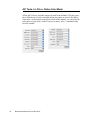
The Advanced Image Correction Tools ......................................................................... 70
The LCH Color Model ................................................................................................... 71
AIC Tools in LCH vs. Native Color Mode .................................................................... 72
AIC Tools and your Image Type .................................................................................... 73
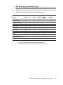
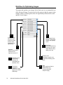
Workflow for Optimizing Images .................................................................................. 74
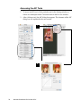
Accessing the AIC Tools ................................................................................................ 76
Elements of the Advanced Image Corrrection screen .................................................... 77
The Action Buttons ........................................................................................................ 78
Default button ......................................................................................................... 78
Revert button .......................................................................................................... 78
Cancel button .......................................................................................................... 78
OK button ............................................................................................................... 78
Custom Settings ............................................................................................................. 79
The Default Button ........................................................................................................ 81
Dynamic Range tool ...................................................................................................... 82
White & Black Points tool ............................................................................................. 84
The W&B Points dialog box in Native color mode ................................................ 86
Gradation tool ................................................................................................................ 87
How to read the curve ............................................................................................. 87
Color Cast tool ............................................................................................................... 91
Saturation tool ................................................................................................................ 93
Selective Color tool ....................................................................................................... 94
Tone Curve tool ............................................................................................................ 100
Filter tool ...................................................................................................................... 102
Blur ....................................................................................................................... 103
Sharpen ................................................................................................................. 103
Edge Enhancement ............................................................................................... 103
Emboss .................................................................................................................. 103
Unsharp Masking .................................................................................................. 104
Gaussian Blur ........................................................................................................ 105
Brightness and Contrast tool ........................................................................................ 106
Color Correction tool ................................................................................................... 107
Threshold tool .............................................................................................................. 108
Descreen ....................................................................................................................... 109
v
The Information Window ........................................................................ 110
Elements of the Information window .......................................................................... 110
Color Meter Options .................................................................................................... 112
Creating Color Tag Windows ....................................................................................... 113
The Scan Job Queue Window ................................................................ 114
Elements of the Scan Job Queue window .................................................................... 114
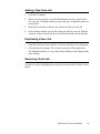
Selecting Multiple Scan Jobs ...................................................................................... 116
Editing Multiple Scan Jobs .......................................................................................... 116
Adding a New Scan Job ............................................................................................... 117
Duplicating a Scan Job ................................................................................................ 117
Removing a Scan Job ................................................................................................... 117
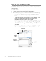
Using the Scan Job Manager button ............................................................................ 118
Appendix A: More Color Matching Information.................................... 119
Appendix B: Kodak Color Management System .................................. 120
vi
Introduction
This Reference manual covers the various commands and features found in the
ScanWizard Pro scanning software for the Mac OS X system. The reference
information is divided into four major sections, corresponding to the four major
windows of the program:
• Preview
• Settings
• Information
• Scan Job Queue
The Reference manual is part of the comprehensive documentation included
with your Microtek scanner package.
Another important component of the documentation, the User's Guide, covers
basic and advanced scenarios for scanning (e.g., how to scan film, how to scan
multiple jobs, etc.).
Reference: The Preview Window
1
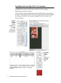
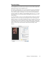
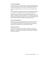
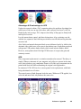
ScanWizard Pro for Mac OS X: The Interface
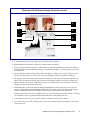
ScanWizard Pro consists of four major windows: Preview, Settings,
Information, and Scan Job Queue.
All four windows appear automatically after ScanWizard Pro is started up the
first time. You may hide or show the Scan Job Queue and Information windows
by clicking on the Hide / Show toggle commands in the View menu of the
Preview window.
Settings
window
contains
scanning
parameters for
image type
and,
dimensions.
Includes image
correction tools
Preview window has commands and tools for
controlling the scanner
Information
window
provides
color
information on
a selected
area of the
image
Scan Job window provides functions for managing
scan jobs
2
Microtek ScanWizard Pro for Mac OS X
Launching ScanWizard Pro
Start ScanWizard Pro from the Applications folder in your Mac OS X system.
The first time you launch ScanWizard Pro, you will be prompted to set up color
matching for your scanner. If you are not sure about what to do, simply click
the OK button to accept the settings. You can always change the settings at a
later time. For more information, see the Color Matching Setup section of the
manual.
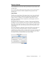
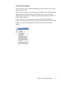
You will also see the ScanWizard Pro menu at the top left portion of your
desktop. Here, you will see commands for specifying your preferences in
ScanWizard Pro, hiding ScanWizard Pro, quitting ScanWizard Pro, etc.
Exiting ScanWizard Pro
To exit ScanWizard Pro, go to the File menu and choose the Quit command, or
press the Apple + Q keys simultaneously.
Reference: The Preview Window
3
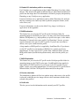
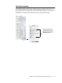
The Preview Window
The Preview window is the prominent window and includes the various
commands and tools for controlling the scanner.
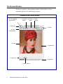
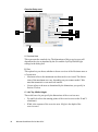
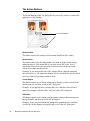
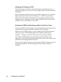
Elements of the Preview window
B. Scan Material
pop-up menu
C. Overview
button
D. Prescan
button
E. Scan
button
A. Menu bar
F. Toolbar
G. Unit of
measurement
H. Rulers
I. Preview area
J. Auxiliary bar
L. Status bar
K. Handy buttons
4
Microtek ScanWizard Pro for Mac OS X
A. Menu bar: This area includes the different menus for controlling and
operating the scanner.
B. Scan Material pop-up menu: This shows the type of your scan material —
Reflective (photos and prints), Positive, or Negative.
C. Overview button: This button previews the specified or entire scan bed.
D. Prescan button: This button previews one or more detailed images of the
area(s) selected by the Scan Frame tool.
E. Scan button: This button starts the final scanning process.
F.
Toolbar: The buttons in the Toolbar perform specific actions on the
Overview or Prescan image. The Toolbar includes the Scan Frame tool,
Zoom tool, Move tool, and Tag Windows tool.
G. Unit of Measurement: Select the unit of measurement for the rulers and the
ruler colors by clicking the arrow at the 0,0 point of the rulers and
choosing from the drop-down menu.
H. Rulers: Rulers are located on both sides of the Preview window to help you
with measurement and alignment.
I.
Preview area: This area in the Preview window shows the Overview or
Prescan image.
J.
Auxiliary bar: This area shows the scan resolution of the preview image
and the Zoom or magnification scale for the image.
K. Handy buttons: These buttons include Zoom in, Zoom out, and the Flasher
for Low Value and High Value Markers.
L. Status bar: This area shows you information pertinent to the operation
underway or being performed.
Reference: The Preview Window
5
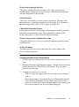
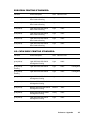
The File Menu
The File Menu lets you do the following:
6
•
Create a new context for scanning
•
Load a previously saved context
•
Save a context for scanning as an extra copy
•
Use the SnapTrans™ Templates feature
•
Show the current context for scanning
•
Exit ScanWizard Pro
Microtek ScanWizard Pro for Mac OS X
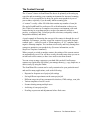
The Context Concept
The “Context” feature in ScanWizard Pro has to do primarily with setting up
scan jobs and customizing your scanning environment for increased scanning
efficiency. It is a powerful tool to help you get the most productivity out of
your scanner, especially if you do many similar scanning jobs.
A “context” is really a Mac OS folder that contains any number of scan job
files and a ScanWizard Pro preferences file with information on these scan
jobs. Think of a context as a complete scan setup or environment, with each
context having its own characteristics, such as scan material (reflective,
positive, or negative film), ColorSync profile selections, scan quality control,
interpolation method, and others.
A good example in illustrating the concept of the context is through the use of
templates. For instance, you may set up four contexts for your most frequent
scanned work — reflective scans, a 35mm template, a 4" x 5" template, and a
negative filmstrip template. You can then switch easily and freely among these
contexts to maximize your productivity. (For more information, see the
SnapTrans Templates command.)
When you quit or switch to another context, the settings of the current context
are automatically saved. You will have exactly the same setup when you run or
switch back to this context, so there is no need to start from scratch.
You can set up as many contexts as your hard disk can hold. And because
contexts are regular Mac OS folders, you manage them (e.g., copy, duplicate, or
delete) easily by using the Finder.
The ScanWizard Pro context can be easily customized to your particular need
and used for many applications, such as the following:
• Repeated or frequent use of project/job settings
• Saving different experiments on the same project/job
• Different setups involving scan material selections, CMS settings, scan jobs
• Various templates of a user's work
• Scanner sharing among multiple users
• Archiving of scan projects/jobs
• Proofing on prescans and adjustments before final scans
Reference: The Preview Window
7
New ScanWizard Context
This command creates a new context folder with default settings for scanning.
Subsequent scan jobs are then stored in the newly created context folder. The
newly created context also becomes the current context.
To create a new context:
1.
Choose New ScanWizard Context from the File menu.
2.
When the browser dialog box appears, create a new folder.
Load ScanWizard Context
This command loads a previously saved context folder. The loaded context then
becomes the current context.
To load a context:
1.
Choose Load ScanWizard Context from the File menu.
2.
When the browser dialog box appears, select the folder to be loaded, and
click the Select button at the bottom of the dialog box.
Save ScanWizard Context As
This command lets you save an extra copy of the current context to a new
location. The settings of the current context are saved first and then copied and
switched to the new location. This is particularly useful when you want to work
on a new context based on the current context settings.
To save a context:
8
1.
Choose Save ScanWizard Context As from the File menu.
2.
When a dialog box appears, choose the folder where the scan jobs will be
saved. Subsequent scan jobs are then saved to the specified folder.
Microtek ScanWizard Pro for Mac OS X
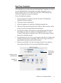
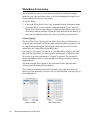
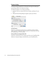
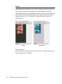
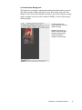
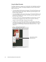
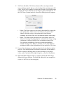
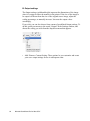
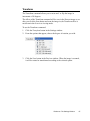
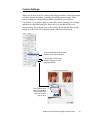
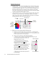
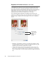
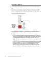
SnapTrans Templates
This command lets you choose the particular SnapTrans™ template you wish to
use with ScanWizard Pro. The templates are holders designed to secure a
variety of films, such as 4"x5" film, 6cm x 9cm film, 35mm filmstrip, and
35mm slide (landscape or portrait orientation).
To use the SnapTrans templates:
1.
Choose SnapTrans™ Templates from the File menu. The SnapTrans
Templates dialog box appears.
2.
Choose the correct scan material.
3.
Select the template to be loaded by clicking the template icon.
4.
Take note of the name and location of the folder to where scan jobs will be
saved, or specify your own folder name and location.
5.
Click the Save button. The selected set of pre-defined scan jobs based on
the template you chose is copied to your designated folder; i.e., a new
"Context" folder has been created for you. The Scan Job window will also
show the pre-defined scan jobs.
6
From hereon, do an overview to see the images in the Preview window, and
continue with the process of matching each overview image with each of
the predefined scan jobs in the Scan Job window.
7.
When you are finished, click the Scan button in the Preview window to
start scanning with the use of your selected SnapTrans template.
Choose your scan
material (step 2)
Folder where
scan jobs will
be saved
(step 4)
Template icon
(step 3)
Reference: The Preview Window
9
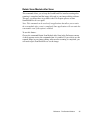
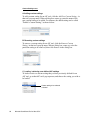
Show Current Context Path
This command shows the current context for scanning. By default, the current
context folder has the same name as your scanner model (ex. ScanMaker
8700), and is located in the Plug-ins folder of your image-editing software.
When you load or create a new context folder, the loaded or newly created
folder then becomes the current context.
To show the current context: Choose Show Current Context Path from the File
menu.
Quit
This command lets you exit ScanWizard Pro.
10
Microtek ScanWizard Pro for Mac OS X
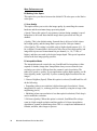
The Scanner Menu
The Scanner Menu lets you:
• Show your scanner model or select a scanner if you have multiple scanners
• Get information about your scanner
• Get scanner information on the SCSI / USB / FireWire chain
• Easily manage the scanners you wish to use with your system
• Perform special scanner controls unique to the scanner
Reference: The Preview Window
11
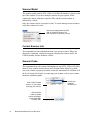
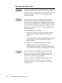
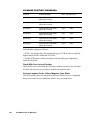
Scanner Model
The scanner model (and its SCSI, USB, or FireWire ID number) is shown at the
top of the scanner. If you have multiple scanners on your system, all the
scanners are shown with their respective IDs, and the current scanner is
indicated by a check.
Only one scanner can be accessed at a time. To switch among various scanners,
select the scanner to be used.
The scanner displayed with its SCSI,
USB, or FireWire ID number. The
current scanner is marked by a check
Current Scanner Info
This command provides information about your current scanner. When you
choose this command, a dialog box appears showing the scanner model, the
USB ID number, and the firmware version.
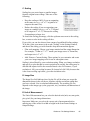
Scanner Probe
This command shows the scanner information on your SCSI, USB, or FireWire
chain. If your scanner does not show in the Scanner Probe dialog box, make
sure your scanner is properly installed, connected, and turned on, and then click
the Probe button. For details on connecting your scanner, refer to your scanner
hardware installation guide.
SCSI / USB / FireWire
devices on your system
(including your scanner)
Click the Probe
button to update
scanner information
on the SCSI/USB /
FireWire chain
12
Microtek ScanWizard Pro for Mac OS X
Choose your
hardware
interface here
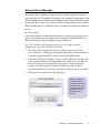
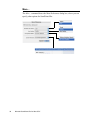
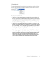
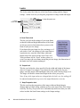
Scanner Driver Manager
The Scanner Driver Manager keeps track of the scanners being used on your
system and the bus / ID numbers occupied by the scanners. By keeping a record
of this information, the Scanner Driver Manager allows ScanWizard Pro to start
up more quickly, as there is no need to look for scanners that are anot available.
When ScanWizard Pro is run the first time, all connected scanners are added to
the list.
To add a scanner:
Follow the hardware installation instructions for connecting a scanner to your
system. You can then use the Scanner Driver Manager in ScanWizard Pro to
add or include the connected scanner to your scanner list.
Note: You will have to follow the steps below if you change hardware
configuration such as the SCSI ID or SCSI bus.
1.
Go to the Scanner menu in the Preview window, and choose Scanner
Driver Manager. A dialog box will appear showing the current scanner list
with the corresponding SCSI, USB, or FireWire bus/ID number.
2.
Click the Find Scanners button. In case you have added new scanners, the
newly found scanners will be appended to the scanner list. If a scanner on
the list is not detected (not turned on, not ready, or removed from the
system), the model will not be removed from the list but will have a
question mark before it. See below for details on how to remove a scanner.
3. Click the Close button to close the dialog box.
Note: For USB and
FireWire scanners,
you will have to follow
the steps below if you
unplug the scanner at
any time during the
ScanWizard Pro
session.
Reference: The Preview Window
13
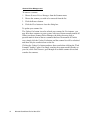
Scanner Driver Manager cont.
To remove a scanner:
1. Choose Scanner Driver Manager from the Scanner menu.
2. Choose the scanner you wish to be removed from the list.
3. Click the Remove button.
4. Click the Close button to close the dialog box.
To update your scanner list:
The Update List button is used to refresh your scanner list. For instance, you
may have three scanners on your system, with two of them currently turned off.
When you choose Scanner Driver Manager, the dialog box may show a
question mark in front of the two scanners that have been turned off. In this
case, simply click the Update List button, and the scanner list will be refreshed
and show only the connected one on the list.
Clicking the Update List button produces faster results than clicking the "Find
Scanners" button. Update List simply searches the scanner models already on
your list, while Find Scanners goes through all available scanner drivers and
searches for scanners.
14
Microtek ScanWizard Pro for Mac OS X
Scanner Controls
This command lets you use some of the special features of your scanner, such
as lamp control.
Note: Not all scanner models support these features. If your scanner model is
not supported, the Scanner Controls command will be grayed out in the
Scanner menu.
Lamp Control
This the power-saving feature of the scanner lamp to save energy and extend
the life cycle of the lamp. By default, the lamp turns off automatically if the
scanner is idle for 15 minutes. You can change the lamp idle time in your
preferences or disable this feature completely by unchecking the Auto Power
Saving Mode check box.
By default, the lamp warm-up time is 3 minutes. A lamp warm-up dialog box
will appear if you try to perform a scan or preview operation without the lamp
having fully warmed up. If the lamp is not fully warmed up, the light intensity
of the scanner may not be stable and may adversely affect the quality of your
scanned image.
The current lamp status is indicated. You may specifically turn the lamp on or
off if you wish. Please note that the lamp On / Off state is automatically
controlled by the software, and no user intervention is necessary. You may want
to do this manually if and only if you wish to turn on and warm up the lamp a
few minutes before you actually finish your scan job editing.
Reference: The Preview Window
15
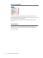
The View Menu
The View menu lets you:
• Select an overview or prescan view of an image
16
•
Magnify or reduce (zoom in / zoom out) the Overview image
•
Resize the Preview window to fit
•
Bring the Settings window to the front
•
Show or hide the Info, Scan Job Queue and Tag windows
•
Show or hide the High and Low Value Markers
•
Show the ScanWizard Pro splash screen
Microtek ScanWizard Pro for Mac OS X
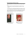
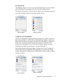
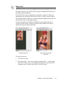
Overview Image and Prescan Image
These commands allow you to switch between Overview or Prescan viewing
modes.
• Overview image: This is an image obtained when you click the Overview
button in the Preview window. The image shows you whatever is on your
scan bed.
• Prescan image: This is a detailed image obtained from selecting an area in the
Overview image and then clicking the Prescan button in the Preview window.
You can also change the size of the Overview or Prescan image. The size of the
images is determined by the Overview Setup command and the Prescan Setup
command, respectively. For more details, see these commands under the
Preferences menu section.
Overview viewing mode
Prescan viewing mode
Reference: The Preview Window
17
Overview & Prescan cont.
A. To obtain the Overview image: With the image(s) placed on your scanner,
click the Overview button.
B. To obtain the Prescan image:
1.
Click the Scan Frame tool.
2.
Select the area to be prescanned by drawing a frame around the area in the
Overview image.
3.
Click the Prescan button. The Prescan image will then be available for
viewing in the View menu, and a thumbnail of the image will appear in the
Scan Job Queue window.
C. To obtain multiple Prescan images:
18
1.
Define your scan jobs in the Scan Job Queue window (see the Scan Job
Queue window section of the manual for more details).
2.
To select multiple scan jobs, press the Shift key and click the jobs to be
selected in the Scan Job Queue or Preview window.
3.
Click the Prescan button. Multiple prescans are created in the process,
corresponding to the number of scan jobs defined. You can then switch
among the various prescan images for viewing.
Microtek ScanWizard Pro for Mac OS X
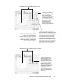
Resize Window to Fit
This command resizes the Preview window, which you may find helpful to do
for conserving space on your desktop monitor (especially after you have
enlarged the Preview window).
To use this feature:
Choose the Resize Window to Fit command. You can also do this by pressing
the Apple command + R keys simultaneously.
Resize before
Resize after
Reference: The Preview Window
19
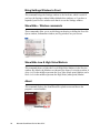
Bring Settings Window to Front
This command brings the Settings window to the forefront, which is useful if
you have the Settings window hidden behind other windows or if you have a
expanded your Preview window such that it covers the Settings window.
Show/Hide... Window commands
These commands allow you to switch between showing or hiding the Scan Job
Queue window, Information window, and Tag windows on your screen.
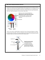
Show/Hide Low & High Value Markers
This command shows or hides the Low & High Value Markers in the Preview
window. By default, the Markers are shown in the form of a circular crossbar. A
white circle in the middle represents the Low Value (black point) Marker, and a
black circle in the middle represents the High Value (white point) Marker.
About
This command displays the ScanWizard Pro splash screen and shows the
program's version number.
20
Microtek ScanWizard Pro for Mac OS X
The Preferences Menu
The Preferences menu lets you:
• Choose the correct scan material
• Specify color matching parameters
• Set up White/black points settings
• Show/hide auxiliary cursor lines
• Control Ovevew and Prescan settings
• Create effects like invert
• Activate the smoked glass effect
• Set other options, such as specifying a working directory for files
Reference: The Preview Window
21
Scan Material
This command allows you to select the correct scan material. Scan materials
can be classified into three types:
• Reflectives, such as photographs or prints.
•
Positive transparencies, such as slides.
•
Negative film, such as the negative film you use for your camera.
The default scan material depends upon the scanner you are using, and the
choices available to you in the Scan Material submenu will also depend on your
equipment.
For instance, the Positive and Negative options appear only if you are using a
dual-bed SnapTrans™ scanner such as the ScanMaker 8700 or if you are using
a Transparent Media Adapter (TMA) with your flatbed scanner.
If you are scanning negatives or positives, make sure you specify the correct
scan material, or you will get inaccurate scanning results.
To choose your scan material:
1.
Choose the Scan Material command in the Preferences menu. From the
submenu that appears, select your scan material; a check will appear next
to the selected option.
2.
Alternatively, you can click the Scan Material pop-up menu and then
choose the correct scan material from the drop-down menu that appears.
Scan
Material popup menu
22
Microtek ScanWizard Pro for Mac OS X
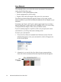
Color Matching Setup
Color Matching is an important feature of ScanWizard Pro that ensures
consistent color — from the initial input stage when an image is captured by
the scanner, to the final output stage when the image is output to your monitor
or printer (through either the Kodak CMS or Apple ColorSync™ technology).
Color matching is a critical component in the imaging process, because the
color space of your monitor is different from that of your printer (in terms of
output devices), just as the color space for RGB mode is different from the
color space for CMYK mode (in terms of image types). For this reason, color
matching was developed to allow an equivalent "mapping" of colors from one
device or from one color space to another, ensuring that no major color shifts
occur in the transferrence process.
To use the ScanWizard Pro color matching function:
1.
Set up the Kodak CMS and Apple ColorSync features correctly at the time
that ScanWizard Pro is installed. For more information on this procedure,
refer to your Kodak or Apple system documentation.
2.
The first time you launch
ScanWizard Pro, you will be
prompted to set up color
matching for your scanner.
You may also access the
color matching parameters
for ScanWizard Pro at any
time in the future by
choosing the Color
Matching Setup command
in the Preferences menu.
Before you proceed with specifying
your Color Matching Setup
options, you should know if the
image-editing or page-layout
application you use to edit or
process scanned images is
ColorSync-savvy or not (e.g.,
Adobe Photoshop 5.0 or later is
ColorSync-savvy; Adobe
Photoshop 4.0 is not).
This is because the settings in the
Color Matching Setup dialog box
will vary, depending on the
image-editing application you are
using. A non-ColorSync-savvy
application is a program that
does not know how to read or
handle embedded ICC profile
information. In this case, the ICC
profile data is ignored.
For more information, see the
section titled Using images in
third-party applications in the
Appendix.
Reference: The Preview Window
23
Color Matching Setup cont.
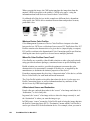
A. Display using monitor compensation
For ColorSync-savvy applications such as Adobe Photoshop 5.0.2 or later,
check this box, which pertains to how your monitor displays color, relative to
the RGB Destination color space. Checking this box ensures that there are no
unexpected color shifts between your selected RGB Destination space and your
monitor. Checking or unchecking this box affects only the way the image data
is displayed and not the image data itself.
For more information, see the section titled Using images in third-party
applications in the Appendix.
B. Monitor
The monitor selection shown here is the monitor set in your Monitor Control
Panel. To verify this information, go to your System Preferences, then Displays.
Your selected monitor will be shown, which should be the same as the entry in
this dialog box. This setting only affects how the image is shown on the screen
— not the final scanned image.
C. Native Mode RGB color matching
This option is available only for Native color space mode. This check box
should generally be checked unless you want to scan raw color data, in which
case you lose the compensatory effects of the Color Matching System. Take
note that it is not desirable to scan in raw data and then perform ColorSync data
conversion, which will not generate the correct CMS effect.
For more information, see the section titled Using images in third-party
applications in the Appendix.
24
Microtek ScanWizard Pro for Mac OS X
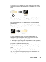
D. Embed ICC destination profile in scan image
For ColorSync-savvy applications such as Adobe Photoshop 5.0 or later, check
this box. This feature will enable ScanWizard Pro to embed the Destination ICC
profile into the image data. The information will then be properly interpreted by
Photoshop or any ColorSync-savvy application.
For non-ColorSync-savvy applications such as Adobe Photoshop 4.0, uncheck
this box if turning it on causes any kind of problem (computer crashes, weird
color effects, etc).
For more information, see the section titled Using images in third-party
applications in the Appendix.
E. RGB Destination
This feature lets you select the ICC profile in the ColorSync folder for
outputting images to the RGB color space. You may select from Scanner RGB,
Monitor, RGB printer (e.g., inkjet printers), a special color space, or the Adobe
Photoshop 5.0 internal color space profile. For Photoshop 5.0 users, you may
export its internal color space to an ICC profile. If you are not sure what to
choose, select your current monitor profile.
A large number of RGB profiles is supplied by ScanWizard Pro. If you do not
see the ICC profile for your monitor or RGB device, contact your device
manufacturer. To load a specific ICC profile from a different folder, click the
RGB profile button (beside the drop-down menu), and select the profile you
need.
F. CMYK Destination
This feature lets you select the ICC profile in the ColorSync profile folder for
outputting images to the CMYK color space. ScanWizard Pro has supplied a
large number of CMYK profiles. If you do not see the ICC profile for your
printer, contact your printer manufacturer. To load a specific ICC profile from a
different folder, click the CMYK profile button and select the profile.
G. Preview check box
This immediately updates the Preview window image when a new color profile
is selected, so that the preview image reflects colors consistent with the newly
selected color profiles.
H. Profile Info
This lets you review the information on the currently used ICC profiles.
Reference: The Preview Window
25
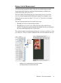
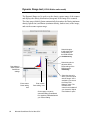
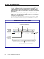
White/Black Points Setup
This command provides you with advanced controls for setting the clipping
points for your white and black points, as well as determining the output levels
for the white/black points on your printer.
To use this feature:
1. Choose the White/Black Points Setup command from the Preferences menu.
2.
As an alternative, you can click this command from the Color Correction
Menu. This is also the same thing as clicking the White/Black points tool in
the Settings window and then clicking the Setup button from the dialog box
that comes up. When the dialog box comes up, specify your preferences.
A. Auto Clipping
The Auto White Point Clipping and Auto Black Point Clipping fields allow you
to specify the percentage by which the white and black points, respectively, can
be clipped from the histogram. The clipping is done after you click the Auto
button in the AIC White/Black Points dialog box.
For example, if you specify 10 percent as your White Point clipping value and
then click the Auto button, the white point on the histogram is adjusted so that
10 percent of the color information is "clipped" or ignored. The resulting 90
percent information leftover is then remapped, resulting in an image with less
highlight detail.
The same principle above applies to the Auto Black Point Clipping feature,
which governs the black point for shadows.
These fields are normally used by more advanced users, and the features are
taken care of automatically if you have set up Color Matching correctly early on
in ScanWizard Pro.
LCH Color Mode
26
Microtek ScanWizard Pro for Mac OS X
Native Color Mode
B. Output Levels
The Minimum Output Level lets you set the minimum output level of the black
point. The higher the percentage value, the lower the contrast will be.
The Maximum Output Level lets you set the output level of the white point. The
lower the percentage value, the lower the contrast will be.
LCH Color Mode
Native Color Mode
C. High and Low Value Markers
This lets you adjust the settings that define the High Value Marker (shown as a
black circle) and the Low Value Marker. The High Value Marker is shown as a
black circle in your preview image, while the Low Value Marker is shown as a
white circle. You can specify the range of the markers to either the entire
preview (by selecting the “Overview or Preview image” option) or to only
within the scan frame (by selecting the “Current Scan Frame”).
In the White/Black Points Setup window, clicking the “Preview” button will
obtain instant results; clicking the “OK” button lets you exit from the Setup
window and applies the High and Low Value Markers setting you have made to
the preview image.
LCH Color Mode
Native Color Mode
Reference: The Preview Window
27
Cursor Auxiliary Lines
This command allows you to show or hide cursor auxiliary lines to help you
define a scan frame or measurement off the rulers more precisely. The cursor
auxiliary lines show only when the Scan Frame tool is selected.
To use this feature:
1. Choose the Cursor Auxiliary Lines command in the Preferences menu.
From the submenu that appears, select how the cursor lines will appear.
2.
•
On both the x (horizontal) and y (vertical) axis
•
On the x axis only
•
On the y axis only
•
None (no cursor lines)
Click the Scan Frame tool. When you move the pointer to the image, the
cursor auxiliary lines will appear.
Cursor
Auxiliary Lines
28
Microtek ScanWizard Pro for Mac OS X
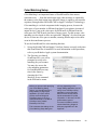
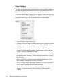
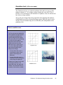
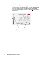
Overview Setup
This command lets you set the area you want to overview off the scanner bed
and provides some overview options as well.
By default, ScanWizard Pro overviews the maximum scan area as determined
by your scanner model's bed size. You can, however, customize the overview
area so that the scanner consistently overviews only the specific dimensions
you have in mind. For example, if your maximum scan area is 8.5" x 14", you
can customize the overview area so that it consistently overviews, say, 4" x 8"
of the bed size.
As a rule of thumb, it is best to use the default maximum settings. You should
change the overview area only if your subsequent overview is too large to be
shown in entirety, or too small for reliable previewing. A smaller overview area
will increase the overview resolution for clearer image viewing. You may also
wish to change the size of your overview to improve performance. Generally, a
shorter overview time results from the scanner motor travelling a lesser
distance.
Reference: The Preview Window
29
Overview Setup cont.
B
C
D
A
E
F
G
H
A. Overview Area
This represents the scan bed size. The dimensions of this overview area will
depend on the size as stipulated by the Size and the Left/Top/Width/Height
settings in the dialog box.
B. Size
This option lets you choose whether to do an overview of the Maximum area or
a Custom area.
• Maximum refers to the maximum area that can be overviewed. The dimensions of the maximum area vary, depending on your scanner model. Take
note that transmissive scan areas are smaller.
• Custom refers to the area as determined by the dimensions you specify in
Section C below.
C. Left, Top, Width, Height
These edit boxes let you specify the dimensions of the overview area.
• Top and Left refer to the starting points of the overview area on the X and Y
coordinates.
• Width is the expanse of the overview area. Height is the depth of the
overview area.
30
Microtek ScanWizard Pro for Mac OS X
D. Keep Overview Image After Quit
If this box is checked, the overview image will be kept when you quit
ScanWizard Pro, and the same overview image will be displayed again when
you run ScanWizard Pro the next time.
E. Fast Overview
If this box is checked, the overview process is speeded up. The trade-off to
increased speed is a slightly downgraded overview image. If you do not care
about the image quality of the overview image, check this box.
F. Warn Me if Overwriting Prescan
If this option is checked, a confirmation message appears, notifying you that a
previously prescanned image exists. This confimration is usually useful
because doing a new overview will delete all prescan images.
G. Auto Overview when ScanWizard Pro is Run
If this box is checked, an overview is performed automatically when you run
ScanWizard Pro.
H. Overview button
This button performs an overview and shows the overview image in the
Overview Setup dialog box.
Changing the Size of your Preview Area
1.
Go to the Preferences menu in the Preview window, and choose Overview
Setup.
2.
When the Overview Setup dialog box appears, click the Overview button to
preview the entire bed. This will help you determine how you wish to
resize the overview area.
3.
To change the overview area, you can:
•
Drag a rectangle that approximates the size of the overview that you
wish; or
•
Enter the appropriate values for the Top, Left, Width, and Height edit
boxes. The new dimensions will take effect on the next Overview —
when you click the Overview button again in the Preview window (not
the Overview button in the Overview Setup dialog box).
Reference: The Preview Window
31
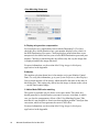
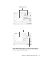
Prescan Setup
The Prescan Setup command lets you determine the margin surrounding the
prescan image and the size of the prescan image.
To change the margin or size of the prescan image:
1.
Go to the Preferences menu in the Preview window, and choose Prescan
Setup.
2.
When the Prescan Setup dialog box appears, specify your choices.
A. Fast Prescan
If this box is checked, the prescan process is speeded up, but the resulting
image is grainier. If unchecked, the prescan process is slowed down a bit, but
the resulting image is of better quality.
B. Keep All Prescan Image(s) After Quit
If this box is checked, the preview images stay after you exit ScanWizard Pro.
Otherwise, all prescan images are deleted after you exit ScanWizard Pro.
32
Microtek ScanWizard Pro for Mac OS X
C. Prescan Image Margin
This option allows you to specify how wide or narrow the margin around the
scan frame is for the prescan image. Options are: Minimal, Small, Medium, and
Large. Smaller margins give you more room to capture the preview image,
while larger margins will allow you to have more room to expand your scan
frame.
This is helpful because selecting the exact scan frame (through the Scan Frame
tool) can never be a completely accurate process, and what appears to have
been selected by the scan frame when you view the image in the lowerresolution overview may or may not actually include the portion you wish. The
margin — depending on how wide or narrow it is — can then provide a berth
or allowance for extending the boundaries of the scan frame around the prescan
image. Margin options include minimal, small, medium, and large.
D. Prescan Image Dimension
This option lets you specify how large the prescan image will be: Full screen
("screen" meaning your main monitor), 75% screen, 50% screen, and Fit
Preview Window. The larger the size, the higher the prescan resolution. The
maximum prescan resolution is the scanner's optical resolution.
E. Background Prescan
If checked, the background prescan function is enabled. You can assign a
number of scan jobs to execute a prescan while carrying out other jobs in the
meantime (e.g., performing color correction to other scan jobs). If unchecked,
this function is disabled.
Reference: The Preview Window
33
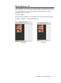
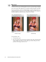
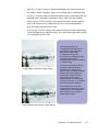
Invert
This command inverts images of all scan jobs. Take note that all scan jobs are
inverted at the same time; you cannot invert an individual scan job alone.
When an image is inverted, the brightness value of each pixel is converted to its
inverse value. In the case of 24-bit images, for example, a pixel in a positive
image with a value of 255 is changed to 0, and a pixel with a value of 5 is
changed to 250.
Original
Inverted image
To use this feature:
Choose the Invert command in the Preferences menu. A check appears next to
the command when it is enabled.
34
Microtek ScanWizard Pro for Mac OS X
Retain Scan Module after Scan
This command allows you to keep the ScanWizard Pro interface running after
scanning is completed and the image delivered to your image-editing software.
This way, you do not have to go back to the File-Acquire process to start
ScanWizard Pro all over again.
Note: This command can be used only in applications that allow you to retain
the scan module after a scan is completed. Some applications will not retain the
scan module even if this option is enabled.
To use this feature:
Choose the command Retain Scan Module after Scan in the Preferences menu.
A check appears next to the command when it is enabled. If you wish to see the
scanned image in your image-editing software after scanning is completed, you
will need to quit ScanWizard Pro to see the image.
Reference: The Preview Window
35
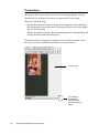
More...
The More... command shows the More Preferences dialog box, where you can
specify other options for ScanWizard Pro.
36
Microtek ScanWizard Pro for Mac OS X
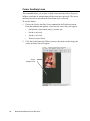
A. Smoked Glass Background
This option lets you apply a smoked glass background that makes your scan
jobs stand out more clearly and allows you to focus on the scan jobs. This
feature can also be used for multiple scan jobs to show their respective image
modes (example: one job in color, another in B&W), as well as their imageediting settings.
The framed part of the
image (inside the marquee)
stands out clearly.
Applied to the rest of the
image is the smoked glass
background (shaded gray
area surrounding the
selection or framed area).
Reference: The Preview Window
37
More Preferences cont.
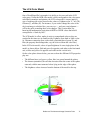
B. Working Color Space
This option lets you choose between the default LCH color space or the Native
color space.
C. Scan Quality
This option allows you to select the image quality by controlling the scanner
hardware and the maximum image processing depth.
• Speed: Choose this option if your primary concern during scanning is speed.
Image data is delivered faster and the image data is processed in 8 bits per
channel.
• Quality: This is the default setting. Scanned data is delivered a little slower
but in high quality, and the image data is processed in 8 bits per channel.
• Best Quality: This setting is available only to higher-depth scanners (10-, 12bit, or higher). Scanned data is delivered a little slower but in high quality, and
image data is processed in maximum bits per channel (i.e., 10-, 12-bit, or
higher), and then converted to the desired output depth. This special operation
results in the best image quality possible.
D. Interpolation Mode
The interpolation mode controls the way ScanWizard Pro interpolates (either
expands or shrinks) image data. Interpolation always occurs when the scan
resolution you select is different from the scanner's optical resolution. The
trade-off is speed vs. quality. If your application requires higher quality, use Bilinear (Quality) mode, especially if you are scanning higher-resolution line art
images.
1. Nearest Neighbor (Speed): When this option is selected, ScanWizard Pro will
do the following:
• Expanding (when scan resolution is higher than optical resolution): Linear
interpolation is used (i.e., makeup pixels are created by using the average of the
neighboring pixels).
• Shrinking (when scan resolution is less than optical resolution): Pixel drop is
used to match the resolution.
2. Bi-linear (Quality): When this option is selected, ScanWizard Pro always
scans in a high-enough resolution and then applies a bi-linear interpolation
algorithm to expand or shrink image data. This is a complicated mathematical
formula, and thus, takes longer to process.
38
Microtek ScanWizard Pro for Mac OS X
E. Scratch Directory
The scratch directory is the folder where ScanWizard Pro creates temporary
files, with the temporary files deleted at the end of an operation. You should
change to a different folder only if the scratch directory is located in a disk
volume that is too small for scanning operations. To specify a new scratch
directory, choose Other Directory... from the menu.
Reference: The Preview Window
39
The Correction Menu
The Correction Menu lets you use the Advanced Image Correction (AIC)
features of ScanWizard Pro. The commands in the Correction menu correspond
to the AIC buttons in the Settings window.
For more information, see the section of the manual on Advanced Image
Correction.
The Help Menu
The Help menu lets you access on-line help for ScanWizard Pro and the
Microtek web site. The contents of this menu may vary and will depend on
your scanner package.
40
Microtek ScanWizard Pro for Mac OS X
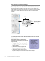
The Toolbar
Scan Frame
Zoom
Move
Tag Windows
Reference: The Preview Window
41
Scan Frame tool
The Scan Frame tool lets you select the area to be scanned or prescanned. You
can have multiple scan frames, but only one scan frame can be current at a
time; the current scan frame is indicated by a flashing marquee. Multiple scan
frames can be more easily distinguished if you turn on the Smoked Glass
Background command (in the Preferences menu).
Resize the
frame by
dragging
To use the Scan Frame tool:
42
1.
Click the Scan Frame tool.
2.
Move the pointer (now a crossbar) to the Overview image, and draw a
frame enclosing the area to be selected. When you release the mouse, a
flashing marquee will indicate the scan frame. To create multiple scan
frames, hold down the Shift key and drag your next scan frame.
3.
To resize the scan frame, drag a corner of the scan frame and resize to the
desired area you want.
4.
To change the position of the scan frame, drag inside the scan frame and
move to a new location
Microtek ScanWizard Pro for Mac OS X
Zoom tool
The Zoom tool lets you zoom in (magnify) and zoom out (reduce) your view of
the image. Only your view of the preview image is changed; the actual size of
the image remains unaffected.
Each click of the zoom tool magnifies or reduces by a factor of 2. Thus, the
magnification levels increase from 100% to 200%, to 400%, to 800%, and to
the maximum 1600%. When you reach the maximum magnification factor, the
center of the Zoom tool will appear empty.
To zoom out (reduce), hold down the Option key and with the Zoom tool
selected, click the image. A minus sign will be in the middle of the lens to
indicate the image is being zoomed out.
Original image view
Image view enlarged with
Zoom tool
To use the Zoom tool:
1.
Click the Zoom tool.
2.
Place the pointer — now a lens with a plus sign inside it — on the image
and click. To reduce the view, hold down the Option key (the Zoom tool
changing to show a minus sign inside it), and click again.
Reference: The Preview Window
43
Move tool
The Move tool lets you scroll through an overview or prescan image, allowing
you to move parts of the image into view quickly without using the scroll bars.
You can use the Move tool for scrolling through zoomed-in images that were
enlarged through the Zoom tool, or for scrolling through parts of an image not
included completely within the frame of the preview window.
Zoomed-in image
Scrolled image
To use the Move tool:
44
1.
Click the Move tool.
2.
Move the pointer (now in the form of a hand) to the image. Hold down the
mouse and move the Move tool left, right, up, or down, and you will see
portions of the image come into view.
Microtek ScanWizard Pro for Mac OS X
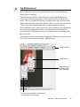
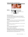
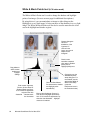
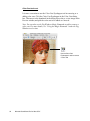
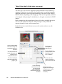
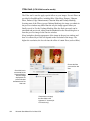
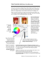
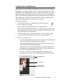
Tag Windows tool
The Tag Windows tool lets you set the shadow (black) point and highlight
(white) point of an image.
It also creates tag windows, which are used to isolate and identify precise
colors in a given image, providing a visible and retrievable record of color
values. This way, ScanWizard Pro lets you pinpoint and “tag” the color on the
image, showing you the original or “Before” values, as well as the corrected or
“After” values following the application of image adjustment controls.
The Tag Windows tool is useful especially if you are making color adjustments
based on known mathematical values, as the displayed color information
provides a basis for knowing how close or accurate are the color changes that
have been made.
Also in the tag window are the Magic Diamonds for adding or removing a color
cast, as well as for setting the shadow / highlight point.
Tag Windows tool
Tag Windows
Magic Diamonds
(L-R black, RGB,
white diamonds
Color Strip shows selected or adjusted color
for a particular area in the image
Reference: The Preview Window
45
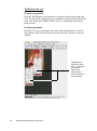
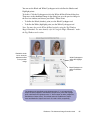
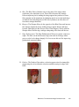
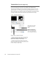
Tag Windows tool cont.
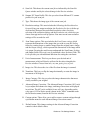
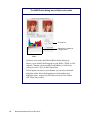
To create a tag window
Click the Tag Windows tool, then move to any part of the preview image and
click. The tag window displays the x/y coordinates of the selected pixel and the
color value of that pixel (RGB, CMYK, Lab, etc.), depending on the image
mode selected.
To close a tag window
Click the Close box on the upper left corner of the Tag window. To close all
Tag windows, hold down the Option key, then click the Close box of any tag
window.
Tag Windows at
these points show
the x, y coordinates
and the color
values of the
selected pixels
(maroon and brown
in this example)
46
Microtek ScanWizard Pro for Mac OS X
Choosing the White & Black Points of an image
There are two ways to choose the white and black points of an image:
A. By using the Tag Windows tool in the Toolbar.
1) To choose the highlight (white) point in an image, click the Tag
Windows tool, press the Apple Command key, and click on a white
point in the image.
2) To choose the shadow (black) point in an image, click the Tag
Windows tool, press the Option key, and click on a black point in the
image.
B. By using the Magic Diamonds. See the next section for details.
Tag Windows tool
Magic Diamonds
Reference: The Preview Window
47
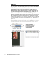
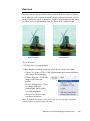
Using the Magic Diamonds
The Magic Diamonds is another way of setting the white (highlight) and black
(shadow) point in an image. The Magic Diamonds can also be used to add or
remove a color cast.
•
To set the shadow (black) point on the image: Click the Tag Windows tool,
then click a black point in the image. When the tag window appears, click
the Black Magic Diamond.
•
To set the highlight (white) point on the image: Click the Tag Windows tool,
then click a white point in the image. When the tag window appears, click
the White Magic Diamond.
•
To remove a color cast: Click the Tag Windows tool, then click a color in
the image that corresponds to the color cast to be removed. In the tag
window, click the RGB Magic Diamond in the middle
•
To add a color cast: Click the Tag Windows tool, then click a color in the
image that corresponds to the color cast to be added. Hold down the Option
key, and click the RGB Magic Diamond (the diamond will have a + sign
next to it.)
.
Black, RGB, and White
Magic Diamonds
48
Microtek ScanWizard Pro for Mac OS X
To restore original settings
Do either of the following:
1.
Select No Correction from the White/Black points menu in the Settings
window.
2.
Click the Default button in the Settings window.
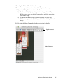
To display color information for a pixel or an averaged area
1.
Click the Tag Windows tool.
2.
As you pass over a point in the image, see the Information window — the
values will be displayed in the Input and Output area of the Information
window. These values are based on the sample size you selected.
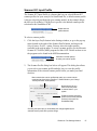
To change the sample size of the Tag Windows tool
1.
Open the Information window by choosing the Show Info Window
command in the View menu.
2.
Click the Color Meter Options button.
3.
Choose your options.
4.
•
Select Value or Percent to determine how the pixel information will be
displayed.
•
Select the sample size. For instance, the 1 by 1 option will display the
value of one pixel — the one in the middle of the sample size area.
The 3 by 3 option reads the average value of an area that is 3x3 pixels
To choose display mode, select Native or LCH. Take note that the Value
and Percent options are grayed out if you are working in the default LCH
color mode and become active only in Native color mode.
Color Meter
Options button
Reference: The Preview Window
49
Overview, Prescan, Scan
The Overview button previews the image on the scan bed. By
default, the entire scan bed is previewed when you click the
Overview button. To change the area to be previewed, specify
the dimensions in the Overview Setup command (in the
Preferences menu).
The Prescan button previews in high resolution the area
selected by the scan frame tool. Multiple prescans can be
done if you have several selected scan jobs, and the prescans
are done one after another in the order that they are listed in
the Scan Job Queue window. Options governing the prescan
function can be found in the Prescan Setup command in the
Preferences menu.
To obtain multiple prescan images:
1.
Define your scan jobs in the Scan Job Queue window
(see the Scan Job Queue window section for more
details).
2.
To select multiple scan jobs, press the Shift key and click
on the jobs to be selected in the Scan Job Queue or
Preview window.
3.
Click the Prescan button in the Preview window.
Multiple prescans are created in the process,
corresponding to the number of scan jobs defined, and
you can then switch among the various prescan images.
The Scan button scans the images on your scanner and
delivers the images to your image-editing software. The
images that are scanned are the scan jobs that have been
checked in the Scan Job Queue window.
Note: If the Retain Scan Module After Scan option (in the
Preferences menu) is checked, you will need to exit
ScanWizard Pro to see the scanned image in your imageediting software.
50
Microtek ScanWizard Pro for Mac OS X
Rulers, Unit of Measurement
The rulers on the top and left sides of the Preview window help you with
measurement and alignment, marking off measurement according to the
selected unit (inch, pica, pixel, etc.).
The rulers change when dimensions are altered in the preview area of the
Overview Setup command (in the Preferences menu). For example, if you
change the preview area size from 5" x 8" to 6" x 9", the rulers will change
accordingly.
The unit of measurement can be selected in two ways:
• Through the Unit box in the Settings window.
• Through the arrow at the corner where the rulers meet in the Preview
window. The drop-down menu through this method also lets you format the
text color and background color of your rulers.
The options for unit of measurement include inch, centimeter, millimeter, point,
pica, and pixel. The pixel option is dimmed if the selected resolution unit is lpi.
Select the unit of measurement for the rulers in either
the Settings window or the Preview window.
Reference: The Preview Window
51
Preview Area
The preview area is where the overview or prescan image appears. You can
increase the size of the preview area to see more detail in your image.
Take note of the following:
•
When you perform an overview, the overview image size is determined by
the current preview area dimension. The bigger the preview area, the higher
the preview resolution.
•
When you perform a prescan, the prescan image deteail is determined by the
settings in the Prescan Setup dialog box.
For details on how to change the actual preview area of the scan bed, refer to
the Overview Setup command in the Preferences menu section.
Preview area
To increase or
decrease the
preview window,
drag the window to
resize
52
Microtek ScanWizard Pro for Mac OS X
Auxiliary information and Handy buttons
Resolution for
Overview or
Prescan image
Zoom scale
Zoom out
Flasher for High and Low Value
Markers
Zoom in
Preview image resolution
This shows the image resolution for the Overview or Prescan image. The
preview image resolution will change, according to the size of the preview
window and the amount of available memory. To resize preview window, drag
any side or corner of the window.
Zoom scale
This shows the zoom factor, or how many times the image has been magnified
using the Zoom tool or the Zoom in / Zoom out icons to the right of the Zoom
scale. You may select the exact Zoom scale from here.
Zoom-out
This lets you reduce a zoomed-in or magnified image one level down with each
click, up to the minimum 100% view.
Zoom-in
This lets you magnify or enlarge the image one level up with each clickEach
time you click, up to the maximum 1600% view.
Flasher for High and Low Value Markers
When the overview or prescan image is displayed, the High Value and Low
Value Markers are shown. If the two markers cannot be visually detected with
ease (depending on how your image may obscure the markers), clicking the
flasher activates the markers to flash a few times for easier detection, allowing
their locations on the oveview or prescan image to be seen.
Reference: The Preview Window
53
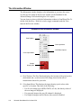
The Settings Window
The Settings window contains the parameters for outputting your scanned
image for the current scan job and includes the advanced image correction tools
of the program.
Elements of the Settings window
A. Scan Job
B. Scanner ICC Profile
C. Type
D. Resolution settings
F. Unit of measurement
E. Scan Frame
options
G. Image Size
H. Transform
I. Image Category
J. Advanced Image
Correction (AIC) tools
K. Custom options
L. Default button
54
Microtek ScanWizard Pro for Mac OS X
A. Scan Job: This shows the current scan job as indicated by the Scan Job
Queue window and by the selected image in the Preview window.
B. Scanner ICC Input Profile: This lets you select from different ICC scanner
profiles for your scan job.
C. Type: This shows the image type of the current scan job.
D. Resolution settings: This area includes the following: the Resolution box
for specifying your output resolution; the Resolution list box (with the up/
down arrows) that provides predefined resolution values for easier
selection of the resolution setting; and the Resolution unit, which lets you
choose from ppi and several lpi options. Your most recent scan resolution
settings will be recorded as well.
E.
Scan Frame options: This area includes the Scan Frame settings which
represent the dimensions of the image that you wish to scan; the Scaling
factor for creating larger or smaller images from the original source image;
and the Output settings, which represent the dimensions of the image when
it is output. Pressing the small arrows underneath the Scan Frame, Scaling,
and Output fields will reveal a set of predefined values for those fields. The
Locks provide you with additional functions for setting the scan frame.
F.
Unit of measurement: This lets you choose your desired unit of
measurement, which will then be reflected in the rulers alongside the
Preview window. Choose from inch, cm, mm, point, pica, or pixel.
G. Image size: This shows the size of the file when the image is scanned.
H. Transform: This lets you flip the image horizontally or rotate the image in
increments of 90 degrees.
I.
Image Category: This lets you select the image characteristics that most
closely resemble your original.
J.
Advanced Image Correction : The Advanced Image Correction (AIC) tools
let you adjust and enhance the image, and image corrections are displayed
in real time. The AIC tools available for use will vary, depending on the
color space (LCH or Native mode) chosen in the "More" command under
the Preferences menu (found in the Preview window).
K. Custom options: These allow you to add or remove custom settings through
a pull-down menu for each Advanced Image Correction control.
L.
Default button: This changes settings in the Advanced Image Correction
controls to their default values.
Reference: The Settings Window
55
Scan Job
The Scan Job box shows the currently selected scan job, which is also shown in
the Scan Job Queue window and the Preview window.
There is always at least one scan job in existence (by default). If you have
multiple scan jobs, not only are these reflected as multiple entries in the Scan
Job Queue window and as multiple images in the Preview window, they will
also be shown as multiple entries in the Job box of the Settings window.
To select from multiple scan jobs, choose the scan job you wish in the Job box;
this will automatically select the corresponding scan job in the Preview and
Scan Job Queue windows as well. Conversely, selecting a scan job in either the
Preview or Scan Job Queue window will automatically show that selection in
the Job box.
This means that a quick look at the Job box, the Preview Window, or the Scan
Job Queue window can show you which is your currently selected scan job.
Correspondence between the
Job box in the Settings
window and the current scan
job in the Preview and Scan
Job Queue windows
56
Microtek ScanWizard Pro for Mac OS X
Scanner ICC Input Profile
The Scanner ICC Input Profile is a feature that lets you select different ICC
scanner profiles for your scan job. In ScanWizard Pro, a default scanner profile
is always selected (provided with your scanner model). In the example below,
the Microtek ScanMaker 8700/Reflective profile is the default scanner profile
selection for the ScanMaker 8700.
Default scanner
profile selection
To select a scanner profile:
1.
Click the Input Profile button in the Settings window; or go to the pop-up
menu located to the right of the Scanner Profile button, and choose the
Select Scanner Profile... option. You may also select other profiles
available in the pop-up menu. To create a scanner profile, use the Microtek
Scanner ICC Profiler (MSP) program for Mac OS X. Details on how to use
the program can be found in the MSP documentation.
Click either of these optkons
to select your scanner profile
2.
The Scanner Profile dialog box below will appear. This dialog box allows
you to select your scanner profile and also lets you view the profile
information of the selected scanner profile before you make your final
decision.
Menu contains the scanner profiles that match your current scanner
model and are found in the ColorSync™ Profiles folder in your /Library/
ColorSync/Profiles folder (default)
Browse button lets you
select a scanner profile
in another folder in your
system
Profile Info section shows the
profile of the currently selected
scanner (in this case, the
ScanMaker 8700)
Checking this option lets you immediately see changes applied by the
selected scanner profile to the preview image
Reference: The Settings Window
57
Type
The Type box shows you the image type of the current scan job. ScanWizard
Pro allows direct scanning in the following color spaces described below.
A. RGB: RGB (Red, Green, and Blue) images use three colors to reproduce up
to 68.7 billion colors. Because scanners and monitors are RGB devices, the
RGB color space is the most commonly used space for capturing and
displaying images. ScanWizard Pro offers standard RGB and 48-bit RGB
color selection, with the 48-bit option available for the ScanMaker 5,
ScanMaker 2000, the Artix line of scanners, and other Microtek
professional pre-press scanners.
B. Grayscale: Grayscale images use shades of gray to simulate gradations of
color or tonal values, and contain 8 bits per pixel. The Grayscale 16-bit
option is provided in ScanWizard Pro for professional pre-press scanners.
C. CMYK: CMYK images are made up of the standard four colors (cyan,
magenta, yellow and black or K) for separated film or digital files used for
sheetfed or web offset printing. CMYK mode instantly converts the
scanner’s RGB input to the CMYK color space. CMYK images are fourchannel images, containing 32 bits per pixel.
D. Lab Color: Lab images are three-channel images containing 24 bits per
pixel. Lab mode is useful for editing a pixel’s luminance but not its color
values. Lab mode produces device-independent color and is recommended
for moving images between systems or printing to a PostScript Level 2
printer.
E.
58
Web / Internet Colors: This mode is useful for displaying images on the
Web or Internet. Output for the Web / Internet color mode in ScanWizard
Pro is 8-bit, 256 indexed color images in the sRGB color space.
Microtek ScanWizard Pro for Mac OS X
F.
256 Colors (Default) / 256 Colors (Custom): These are single-channel
images (8 bits per pixel) that use a color lookup table containing up to 256
colors. The file size is smaller for images in this mode. As an initial setting,
selecting 256 Colors (Default) uses an Adaptive palette with Diffusion. If
the 256 Colors (Custom) option is selected, the dialog box below appears.
•
Palette: The Palette option lets you choose the method for creating the
color palette table. Uniform uses a 6-6-6 fixed color palette table.
Adaptive (default) creates a color palette table from the more
commonly used areas of the color spectrum that appears in the image.
•
Dither: The Dither option can improve the color quality of the 256indexed color image for photographs or continuous-tone images, using
a technique of mixing available colors to simulate missing colors.
None provides no dithering. Pattern uses a structured pattern to
simulate missing colors. Diffusion (default) uses the error diffusion
technique to dither colors and produces the best quality for 256 colors.
G. Line art: Line Art images are made up of one bit of color (black or white)
per pixel. Few editing options are available in this mode, but this mode is
useful for images consisting purely of black and white or even single
colors, such as mechanical drawings, blueprints, or fine-line illustrations.
H. Black-and-White Diffusion: This is a single-bit black-and-white image
dithered with error diffusion. The black and white pixels are arranged in a
way as to “fool” the eye into seeing gray.
Reference: The Settings Window
59
Resolution settings
The settings related to resolution include the resolution box, the resolution list
box, and the resolution unit.
Resolution is the sampling of image pixels per measurement unit or the amount
of pixel information stored in an image. Together, the image resolution and
dimensions determine the file size of the image, which is measured in kilobytes
(KB) or megabytes (MB).
The resolution of an image is important in determining the quality of the output
image. Resolution is also directly related to file size, and the higher the
resolution, the larger the resulting file size will be.
When dealing with resolution, remember to distinguish between optical
resolution and interpolated resolution.
Optical resolution is the "real" resolution as measured by the scanner's optics.
Interpolated resolution is software-enhanced resolution and can be useful for
enlarging very small images or for printing line art to obtain superior results.
A. Resolution box
This shows the resolution setting. To set your resolution:
Enter a resolution setting in the Resolution edit box, then press Enter. If the
value you enter is too high or too low, the maximum or minimum resolution
value is entered for you instead.
Depending on the type of image you have selected (grayscale, color, line art,
etc.), a default resolution is displayed in the resolution box. After you enter
your own resolution value, this value is then recorded for subsequent use, until
a new value is entered and takes over.
B. Resolution list box
This provides predefined resolution values for easier selection of the resolution
setting.
To select your setting, press the up/down arrows next to the Resolution box,
and choose your setting from the list box.
60
Microtek ScanWizard Pro for Mac OS X
C. Resolution unit
The unit of measurement for resolution is in ppi (pixels per inch) or lpi (lines
per inch). Take note that lpi settings are dimmed if the ruler unit is in pixels.
To select your resolution unit:
• Choose ppi if your scanned images are intended for on-screen display. In
this case, you need not go higher than the target resolution of your monitor
(usually 72 dpi for Macintosh and 96 dpi for Windows). A higher resolution
value will simply increase the file size of your image without any perceptive improvement in image quality.
• Choose lpi if your scanned images are to be printed. If you choose 1x, for
instance, your scanned image will be printed at 133 lines per inch, resulting
in a 133-dpi image. At 1.5x, the image will be printed at 199.5 dpi; and at
2x, the image will be printed at 266 dpi. The Custom option allows you to
set an lpi value of your own specification.
In choosing an appropriate lpi value, keep in mind that if the resolution is
too low, the image becomes pixelized, resulting in a deterioration of image
quality. (Pixelization is the process in which the Postcript language uses a
single pixel's color values to create more than one halftone dot.) Conversely, if the resolution is too high, the file size becomes unwieldy, and
your file ends up containing more information than the printer needs,
Reference: The Settings Window
61
Scan Frame and related settings
These settings allow you to adjust the various factors that affect your image,
including the width and height of your image when it is first scanned (Scan
Frame settings), the Scaling factor (how big or how small the resulting scanned
image will be), and the dimensions of the image when it is output (Output
settings).
Locks
Scan Frame settings
Output settings
Scaling
The Scan Frame settings, Scaling, and Output Settings work closely with the
Locks beside them.
In the default settings of ScanWizard Pro,
where none of the locks are in place, take note
of the following:
62
Note: When an illegal
value is entered (e.g.,
the input width
exceeds the scan
frame size), the value
will appear in red as
a flag or warning
indicating an out-ofrange value.
•
Changing the Scan Frame settings (width
or height) will change the Output settings
(width or height).
•
Changing the Scaling will change the
Output settings (width AND height).
•
Changing the Output settings (width or
height) will change the Scan Frame settings (width or height).
Microtek ScanWizard Pro for Mac OS X
A. Scan Frame settings
The Scan Frame settings (width and height) represent the area on the scan bed
that you wish to scan.
To specify your settings, enter the dimensions manually in the width and height
edit boxes; or use the Scan Frame tool to define or resize your scan frame.
Changes made in the Preview window are automatically displayed in the Scan
Frame setting edit boxes.
If you wish, you can also choose from a menu of predefined Scan Frame
settings. To do this, point your mouse to the words "Scan Frame" in the Settings
window, and choose the setting you wish from the drop-down menu that
appears.
Reference: The Settings Window
63
B. Output settings
The Output settings (width and height) represent the dimensions of the image
when it is output to either the monitor or the printer. If the size of the image to
be output is different from the size of the original source image, adjust the
scaling percentage, or manually increase / decrease the output values
accordingly.
If you wish, you can also choose from a menu of predefined Output settings. To
do this, point your mouse to the words “Output” in the Settings window, and
choose the setting you wish from the drop-down menu that appears.
•
64
Add / Remove Custom Setting: These options let you customize and create
your own output settings for use in subsequent scans.
Microtek ScanWizard Pro for Mac OS X
C. Scaling
Scaling lets you create larger or smaller images
from the original source image. Take note of the
following:
• Keep the scaling at 100% if you are outputting
at the same size (e.g., a 4” x 5” original to be
output at the same size).
• Reduce the scaling if you are outputting your
image at a smaller size (e.g., a 4” x 5” original
to be output to 2” x 2.5”). Increase the scaling
if outputting at a larger size.
To choose the scaling percentage, click the up/down arrow next to the scaling
box, or enter a value in the scaling edit box.
If you wish, you can also choose from a menu of predefined Scaling settings.
To do this, point your mouse to the words "Scaling" in the Settings window,
and choose the setting you wish from the drop-down menu that appears.
• Film scale mapping: Choose your image material and the output dimension.
For example, “35mm to 5” x 7"” means your image source is 35mm film,
and output size is 5" x 7".
• Add / Remove Custom Setting: These options let you customize and create
your own image-mapping scale for use in subsequent scans.
Scaling is also affected by your resolution setting. When you change resolution
and specify a value that has no exact equivalent for scaling, the scaling may be
affected and adjusts itself to the nearest allowed value. For instance, if your
resolution is 100, your scaling becomes 99 (instead of a full 100), because that
is the closest scaling equivalent, given the resolution value.
D. Image Size
The Image Size field indicates how big the file will be when you accept the
dimensions shown in the edit boxes, together with the resolution setting that
you have selected. Size is calculated automatically. The resulting file size
depends on the image type (color, grayscale, etc); resolution; and dimensions of
the image.
E. Unit of Measurement
The Unit of Measurement lets you select the desired unit (inch, cm, mm, point,
pica, pixel) for your image dimensions.
Important: Make sure you select the correct unit of measurement before
entering any of the values for width or height in the Scan Frame Settings or
Output Settings.
Reference: The Settings Window
65
Locks
The Locks control the behavior of the Scan Frame settings and the Output
settings. A third Lock lets you keep the proportion for image width and height.
C. Keep Proportion lock
A. Scan
Frame lock
B. Output lock
A. Scan Frame lock
This lets you lock in the settings of your scan frame,
so that the width and height dimensions of the frame
are always preserved no matter where you move the
frame in your preview image.
Note: The Scan
Frame Lock and
Output Lock are
each mutually
exclusive. This
means that only
one lock can be
used at a time.
If you know the exact input size for your image, or if
you wish to “lock” the settings of your scan frame to
a particular size, enter the Scan Frame width and
height values first, then click the Scan Frame lock.
Your scan frame will be “fixed” at those values, so
even if you move the scan frame around the preview image, the dimensions of
the frame itself will remain unchanged.
B. Output lock
This lets you lockin the values specified for the width and height of the image
when it is output. For example, if you know the exact output size for your
image, enter the output width and height values first, then click the Output lock.
The image will then be scanned and output at the values you specify.
Note: If any of the input values are changed after the lock is on, the scaling will
be adjusted automatically to preserve the output dimensions correctly.
C. Keep Proportion lock
This lets you keep the proportion of the image width and height despite
changes made to either setting, and thus preserves the aspect ratio of the image
correctly. The Keep Proportion lock is automatically turned on when you enter
values in either the Scan Frame settings or the Output settings.
66
Microtek ScanWizard Pro for Mac OS X
Transform
The Transform command allows you to rotate and / or flip the image in
increments of 90 degrees.
The effects of the Transform command will be seen in the Prescan image or are
after you click the Scan button and scan the image in; the Transform effect is
not shown in the Overview viewing mode.
To use the Transform command:
1.
Click the Transform button in the Settings window.
2.
From the options that appear, choose the degree of rotation you wish.
3.
Click the Scan button in the Preview window. When the image is scanned,
it will be rotated or transformed according to the selected option.
Reference: The Settings Window
67
Image Category
The image category function in ScanWizard Pro applies predefined settings to
your image and brings out characteristics specific to that image type. This is
helpful in providing a more accurate output image.
To select the correct image category, go to the Settings window and choose the
option you wish from the Image Category menu. Select the image category that
corresponds most closely to the image characterstics of your original.
68
•
None: No image category conversion.
•
Standard: Used for an image not falling into any of the categories described
below. You can also use this category for images of good quality (neither
underexposed nor overexposed, with accurate color and tones).
•
Landscape: Used for images with cool atmosphere with broad tonal variation and a wide hue range. Examples: Natural scenery; skyline with an
expanse of blue sky; mountains and fields.
•
Portrait (Skin Tones): Used for images with dominant skin tones and midtone details present. Examples: Portraits and objects with fleece- or skinlike covering.
•
Jewelry (Gold Tones): Used for images featuring dominant gold / silver
hues. Examples: Gold and silver jewelry, silverware.
•
Sunsets: Used for images with warm reddish hues or a color cast reminiscent of sunsets. Examples: Scenes at dusk or twilight.
•
Metallic Subjects: Used for images with broad highlight and shadow details
but with very narrow mid-tone details. Examples: Audio equipment,
Cameras.
Microtek ScanWizard Pro for Mac OS X
• High Keys: Used for images with broad highlight tonal variation but with
less shadow detail. Examples: Snow-covered landscapes; wedding gowns.
• Low Keys: Used for images with broad shadow tonal variation but with less
highlight detail. Examples: Nighttime scenery; dark suits and clothing.
• Underexposed: Used for images with compressed tonal variation particularly in the shadow areas, characterized by an overall dark appearance
typical of underexposed positive film.
•
Overexposed: Used for images with compressed tonal variation particularly
in the highlight areas, characterized by an overall bright appearance typical
of overexposed positive film.
In the example below, an
overexposed original is shown in
two different image categories.
Because the original was
overexposed to begin with,
choosing the Overexposed image
category had the result of
neutralizing the exposure, resulting
in a better image.
Image assigned “Standard” image category
The same original did not fare as
well when it was assigned the
Standard image category (too
bright overall, not enough contrast),
because this image category is
best used for originals of fairly
good quality (sharp, neither
underexposed nor overexposed)
and not, in this case, for an original
with flawed exposure settings.
This example then shows the
importance of choosing the correct
image category that corresponds
most closely to your original to
obtain optimal results.
Image assigned “Overexposed” image category
Reference: The Settings Window
69
Advanced Image Correction Tools
The Advanced Image Correction (AIC) tools form an integral part of
ScanWizard Pro. With the AIC tools, you can adjust or enhance images right
from within ScanWizard Pro and preview the changes to your image even
before you scan.
Before we go to the use of the AIC tools, we will briefly discuss the LCH color
model, which is important for working with images in ScanWizard Pro.This is
followed by other information relating to the LCH model, including the
availability of the AIC tools in LCH vs. Native color mode, and
recommendations on a workflow for optimizing images.
The following topics are covered:
70
•
The LCH Color Model
•
AIC tools in LCH vs. Native Mode
•
AIC tools and your image type
•
Workflow for optimizing images
•
How to access the AIC tools
•
Elements of the AIC dialog box
•
The Action buttons
•
Using Custom Settings
•
Discussion of the individual AIC tools
Microtek ScanWizard Pro for Mac OS X
The LCH Color Model
One of ScanWizard Pro’s strengths is its ability to let you work in the LCH
color space. Unlike the RGB color model, which corresponds to the color space
as defined in monitors and printers, the LCH color model is a more intuitive
way of working with colors, based on the values of Lightness (the “L” in LCH),
Chroma (C), and Hue (H). For instance, if you wish to change the color of the
sky in an image to a darker blue, your own eye — and your own judgment —
will be the guide to making those color changes. This is easier than, say,
knowing the mathematical equivalent in RGB or CMYK values that would
correspond to a “dark sky blue”.
The LCH model, in effect, makes it easier to comprehend colors as they are
couched in the terms we are familiar with: Lightness (how dark or light a color
is), Chroma or saturation (how rich or dull a particular hue of green is), and
Hue (the property that distinguishes, say, the color red from the color blue.)
In the LCH color model, colors of equal brightness lie on a single plane of the
model, as shown below. Red and green lie opposite each other on the horizontal
axis, as blue and yellow lie opposite each other on the vertical axis.
On the color sphere shown below, you can see how the different LCH properties
play out:
• The different hues (red, green, yellow, blue) are spread around the sphere.
• The chroma (saturation) for each hue increases from the center of the sphere
outward, with the most saturated colors lying on the edge of the sphere.
• The brightness values increase from the bottom of the model to the top.
Reference: The Advanced Image Correction Tools
71
AIC Tools in LCH vs. Native Color Mode
All the AIC tools are available when you work in the default LCH color space,
but a different set of tools is available when you choose to work in the Native
color space. As discussed in an earlier section of the manual, you can select the
color space of your choice in the Preferences menu | More... command in the
Preview window.
72
Microtek ScanWizard Pro for Mac OS X
AIC Tools and your Image Type
The AIC tools do not apply to all image types. See the table below to determine
which AIC tool can be used for a particular image type.
RGB
CMYK
Lab
Gray
Line Art
Dynamic Range
V
V
V
V
White/Black Points
V
V
V
V
V
Gradation
V
V
V
Color Cast
V
V
V
Saturation
V
V
V
Selective
V
V
V
Tone Curve
V
V
V
Filter
V
V
V
V
Descreen
V
V
V
V
Brightness & Contrast
V
Color Correction
V
B&W
Diffusion
Remark
V
*
V
V
**
V
* For Line art, Gradation tool becomes the "Threshold" tool.
** For negative film, this function changes to "Film Type" selection.
Reference: The Advanced Image Correction Tools
73
Workflow for Optimizing Images
To prepare and optimize your images for the final scan, we recommend the use
of the Advanced Image Correction tools in the sequence that they appear in the
Settings window. Following this order will significantly influence the overall
quality of your images.
2
1
Dynamic Range
Manual or auto
determine image
density range
(darkest tone to
lightest tone)
White & Black Points
Manual or auto-adjust
shadow and highlight
points
4
3
Gradation
Manual or auto-adjust
midtones of the
Lightness channel "L"
5
7
74
Saturation Curve
Adjust image
saturation by
manipulating the
saturation curve
Tone Curve
Adjust tonal
distribution of each
channel of a CMYK/
RGB image
Microtek ScanWizard Pro for Mac OS X
6
8
Color Cast
Adjust gray balance by
removing color cast or
adjust desired cast by
adding color cast
Selective Color
Manipulate a specific color
range without affecting other
colors
Filter
Apply a particular filter for
special effects (e.g.,
unsharp masking to
sharpen image)
The sequence is the same if you are working in Native color mode. However,
the Gradation, Color Cast, Saturation, and Selective Color tools (#3 to #6) will
not be available. The Brightness / Contrast and Color Correction tools are
offered in their place.
The Brightness /
Contrast and Color
Correction tools are
offered in the Native
color mode
Reference: The Advanced Image Correction Tools
75
Accessing the AIC Tools
1.
To access an AIC tool, click a particular tool in the Settings window or
choose its counterpart in the Correction menu in the Preview window.
2.
After clicking a tool, the AIC dialog box appears. The elements of the AIC
dialog box are explained in the next section.
1
2
76
Microtek ScanWizard Pro for Mac OS X
Elements of the Advanced Image Corrrection screen
1
2
3
6
4
7
8
5
9
1. Left thumbnail: This shows the image before enhancements are applied.
2. Right thumbnail: This shows the image after enhancements are applied.
3. Preview option: If checked, changes or enhancements are applied immediately to the Preview window
image (for both Overview and Prescan images). If unchecked, changes are seen only after you close the
AIC dialog box.
4. Advanced Image Correction Tools (AIC): These tools adjust or enhance your images. Click any tool in
this area, and see how the core of the AIC screen (#9) changes to reflect the properties of that tool.
5. AIC pop-up menu: This contains custom and other settings you have created for the particular AIC tool
shown. This corresponds to the AIC pop-up menus in the Settings window.n Tools (AIC): These tools
adjust or enhance your images. Click any tool in this area, and see how the core of the AIC screen (#9)
changes to reflect the properties of that tool.
6. Thumbnail option: If checked, the before and after thumbnails are shown in the AIC screen. You can
choose to uncheck this option and hide the thumbnails, since changes can be previewed in the Preview
window. If unchecked, the screen collapses to show only the lower portion of the dialog box.
7. Function icons: These icons (e.g., eyedropper, lens, etc.) perform functions specific to the AIC tool being
used. Function icons are explained in more detail under their corresponding AIC tool.
8. Action Buttons: These carry out a specific action. See the next section for more details.
9. Core of the AIC screen: This is the heart of the AIC screen, and the content here changes to reflect your
selected AIC tool.
Reference: The Advanced Image Correction Tools
77
The Action Buttons
The Action Buttons in the AIC dialog box let you accept, cancel, or control the
application of AIC settings.
The Action Buttons
Default button
This button restores all settings to their default ScanWizard Pro values.
Revert button
This button cancels out the changes that were made with the current imageenhancement tool. This means that if you used several AIC tools, Revert
cancels the effect of only the last used (or current) tool, and preserves the
effects of the other preceding tools.
Example: If you changed the tone curve, applied filters, changed saturation,
then clicked Revert, the saturation changes will be cancelled out, but the altered
tone curve and filters settings remain in effect
Cancel button
This button cancels out all image-enhancement changes you have made to the
current scan job, and then closes the AIC dialog box.
Example: If you applied filters, changed the curve, and then clicked Cancel,
none of the changes will take effect, and you exit the AIC dialog box.
OK button
This button applies to the current scan job whatever image enhancements you
have performed, and then closes the AIC dialog box.
Example: If you increased saturation, changed the gradation curve, and then
clicked OK, all the changes are applied, and you exit the AIC dialog box.
78
Microtek ScanWizard Pro for Mac OS X
Custom Settings
When you click on each AIC setting in the Settings window, a drop-down menu
will show options for adding, removing, or loading custom settings. These
custom settings are settings that you define yourself for your scan jobs.
For instance, if you wish to apply a certain filter (such as sharpen) to an image
and then save that filter setting for future jobs, you can add the filter as a
custom setting. The next time you wish to retrieve that particular filter setting,
simply go to the Filter AIC drop-down menu, and choose that setting.
A user-defined setting that has been
added and can now be retrieved
Lets you add or remove from
the menu settings you have
previously defined
The Custom pop-up
menu in the Settings
window is the same
as the AIC Custom
pop-up menu
Reference: The Advanced Image Correction Tools
79
Custom Settings cont.
A. Adding custom settings
To add a custom setting for an AIC tool, click the Add New Custom Setting... in
that tool's pop-up menu. When a dialog box comes up, enter the name of the
new custom setting to be added. For instance, the added setting can be called
"Debbie's Custom Setting," as shown below.
B. Removing custom settings
To remove a custom setting for an AIC tool, click the Remove Custom
Setting...in that tool's pop-up menu. When a dialog box comes up, select the
particular setting to be removed, then click Remove in the dialog box.
C. Loading / retrieving user-defined AIC settings
To load or retrieve a custom setting that you have previously defined for an
AIC tool, go to that AIC tool's pop-up menu, and choose the setting you wish to
be loaded.
Custom setting to be retrieved
or loaded
80
Microtek ScanWizard Pro for Mac OS X
The Default button
The Default button in the Settings window brings up a dialog box where you
can specify the AIC settings to be reset to their default values. To reset any or a
combination of settings, check the boxes next to the targeted settings.
Checks on these boxes
indicate that these AIC
settings will be restored to
their default values.
Reference: The Advanced Image Correction Tools
81
Dynamic Range tool (LCH & Native color mode)
The Dynamic Range tool is used to set the density capture range of the scanner
and displays the density distribution (histogram) of the image to be scanned.
The Auto range (default) feature automatically determines the Dmin (minimum
density, lighest tone) and Dmax (maximum density, darkest tone) of the image,
and sets the scanner capture range.
Select this option
to adjust the Dmin/
Dmax settings of
the RGB channels
simultaneously
Select this option to
adjust the Dmin/
Dmax settings of the
RGB channels
individually
Drag sliders to
define custom
Dmin/Dmax
settings
Enter custom
Dmax setting
here
Enter custom
Dmin setting here
Click to apply or revert to
automatic setting (ScanWizard
Pro algorithm) if dissatisfied with
your manual setting
82
Microtek ScanWizard Pro for Mac OS X
Select the channel in
which you wish to work
with the image. "All" is
available if you choose
the "Keep Color
Balance" option. The
individual color
channels are available if
you choose the "Adjust
Color Balance" option
You can use the Black and White Eyedropper tools to define the Dmax (darkest
tone) and the Dmin (lightest tone) settings, r espectively.
To do this: Click the Eyedropper tools in the Dynamic Range dialog box. Then
move to the thumbnail image in the dialog box or to the preview image in the
Preview window, and choose your Dmax / Dmin point.
• To define the Dmax (darkest tone) setting, use the Black Eyedropper tool.
• To define the Dmin (lightest tone) setting, use the White Eyedropper tool
White
Eyedropper for
Dmin settings
Black
Eyedropper for
Dmax settings
Reference: The Advanced Image Correction tools
83
White & Black Points tool (LCH color mode)
The White & Black Points tool is used to change the shadow and highlight
points of an image. (See note on next page for additional descriptions.)
By using this tool, you can manipulate an image to either bring out the
highlights in a very dark image, or bring out more of the shadows in a very light
image. The White & Black Points tool can also be used to neutralize the color
cast in the highlight and shadow regions.
Observe histogram
values for
distribution of the
Lightness "L"
channel in the
image, as cursor is
swept around
histogram
Check to auto
neutralize unwanted
color casts in Shadow
(black) area or
Highlight (white) area
Drag sliders to
define custom
shadow and
highlight
settings
Enter custom Lightness,
Chroma & Hue values for
Shadow (Black area) here.
C & H values are applicable
only when the Auto
Neutralize - Shadow check
box is enabled
84
Click to let ScanWizard
Pro determine the shadow
and highlight points
automatically
Enter custom Lightness, Chroma &
Hue values for Highlight (White area)
here. C & H values are applicable only
when the Auto Neutralize - Highlight
check box is enabled
Microtek ScanWizard Pro for Mac OS X
Click to bring up the
White/Black points
setup dialog box. For
more details, see the
section titled White &
Black Points Setup
(under the
Preferences menu in
the Preview window)
You can use the Black and White Eyedropper tools to define the Shadow and
Highlight points.
To do this: Click the Eyedropper tools in the White & Black Points dialog box.
Then move to the thumbnail image in the dialog box or to the preview image in
the Preview window, and choose your Black / White Point.
• To define the Black (shadow) point, use the Black Eyedropper tool
• To define the White (highlight) point, use the White Eyedr opper tool
Note: You may also set the White & Black point by using the Tag Windows
Magic Diamonds. For more details, refer to Using the Magic Diamonds” under
the Tag Windows tool section.
Enable this check
box to show the
adjustment effect
on the prescan
image
White Eyedropper to
define the Highlight
point
Black Eyedropper to
define the Shadow
point
The shadow point is defined as the lightness value “L” in an image that is
output as black (mapped to the Minimum Output Level), while the highlight
point is defined as the lightness value “L” that is output as white (mapped to
the Maximum Output Level). The default values of the Minimum Output
Level and Maximum Output Level are L=5.0 and L=95.0, respectively.
Reference: The Advanced Image Correction tools
85
The W&B Points dialog box in Native color mode
Channel box
Edit boxes for shadow &
highlight values
Sliders
In Native color mode, the White & Black Points dialog box
allows you to modify the histogram in your RGB, CMYK, or Lab
channel. Channels can be modified individually or collectively
(when you select "All") in the Channel box.
Following the selection of your channel, you can move the black
and white sliders below the histogram to set the shadow and
highlight values, respectively. The edit boxes below the sliders
will reflect those values.
86
Microtek ScanWizard Pro for Mac OS X
Gradation tool (LCH color mode)
The Gradation tool lets you adjust the midtones (the mid-level grays) of the
lightness channel “L” of an image without altering the color itself. This is
because even with changes to the luminance or lightness value, the chroma and
hue values are kept constant.
To prevent color images from losing saturation when adjusting the lightness,
ScanWizard Pro provides a Saturation Range option. With this option, colors
outside of a given chroma range are not affected by the manipulation of the
gradation curve.
How to read the curve
.
The Curve shows the relationship
of the brightness changes across
the middle pixels between the
resulting image and the original.
When you open the Curves dialog
box, the line on the graph is
diagonal because the Input and
Output values are the same.
When the curve is moved up or
down, the relationship between
input value and output value
changes accordingly.
•
In areas where the curve is
moved down, pixels in that
portion of the image are
darkened.
•
In areas where the curve is
moved up, pixels in that portion
of the image are lightened.
Contrast in an image can be seen
by the angle of the line. The
steeper the slope, the higher the
contrast. The closer the line is to
horizontal, the lower the contrast.
Original curve
Modified curve
Reference: The Advanced Image Correction tools
87
Gradation tool cont.
Coordinates of cursor
position within the grid
Choose the method you
wish to display the gradation
curve. Select from Curve,
Line, or Gamma
Click Auto to let
ScanWizard Pro
calculate the
Gradation setting
automatically
Click to create handles from
which to drag and manipulate
a portion of the curve . The
more handles are created, the
easier and smoother it is to
manipulate the curve. To
remove a handle, drag it off
the graph or the grid
Check to enable the Saturation Range
option. Then drag the sliders or enter the
values in the edit boxes to define the
saturation (chroma) range. The colors
outside the chroma range will not be
affected by the Gradation curve
In this example, the lower chroma
section (0 to 50) will be affected by the
Gradation adjustment. The higher
chroma section (51 to 100) outside the
chroma range will not be affected
Defining a chroma range is helpful if you
wish to prevent images from losing
saturation or color intensity
88
Microtek ScanWizard Pro for Mac OS X
Appearance of curve if
Method chosen is "Line"
Appearance of curve if Method
chosen is "Gamma"
Instead of dragging the Gamma handle, you can also directly enter the appropriate
Gamma value in the edit box. Dragging points on the curve to a Gamma value
above 1.00, will lighten the dark tones. Dragging points on the curve to a Gamma
value below 1.00 will add shadows to light tones
Reference: The Advanced Image Correction tools
89
Gradation tool cont.
You can also use the Black and White Eyedropper tools to define the Saturation
Range.
To do this: Click the Eyedropper tools in the Gradation dialog box. Then move
to the thumbnail image in the dialog box or to the preview image in the
Preview window, and choose the setting for your high chr oma and low chroma
range.
•
Use the Black Eyedropper tool to define your low chroma range setting.
•
Use the White Eyedropper tool to define your high chr oma range setting.
Black &
White
Eyedropper
tools
90
Microtek ScanWizard Pro for Mac OS X
Color Cast tool (LCH color mode)
The Color Cast tool is used to eliminate any unwanted color casts in an image,
as well as to add a color cast without altering the lightness channel “L” values.
Color Cast Eyedropper
Select whether to add
or remove a color
cast.
"Remove Cast" is the
default
Color (Hue
or Chroma)
Handle
Enter values in the edit
boxes and see how the
handles get positioned in
the color box
Lightness
Handle
Conversely, move the
handles in the color box
and see how the values
change in the edit boxes
Reference: The Advanced Image Correction tools
91
Color Cast tool cont.
It is more convenient to use the Color Cast Eyedropper tool in removing or a
adding color cast. Click the Color Cast Eyedropper in the Color Cast dialog
box. Then move to the thumbnail in the dialog box or the pr eview image in the
Preview window, and pick the color cast to be added or r emoved.
Note: You can also use the Tag Windows Magic Diamonds to add or remove a
color cast. For more details, see “Using the Magic Diamonds” under the Tag
Windows tool section.
Use the Color Cast
Eyedropper to add or remove
a color cast
92
Microtek ScanWizard Pro for Mac OS X
Saturation tool (LCH color mode)
The Saturation Curve tool lets you increase or decrease the color intensity
(chroma or saturation) of an image without altering its hue and lightness values.
Select Saturation method.
"Curve" is the default
Select Saturation Range.
"All" is the default. Other
selections let you change
the saturation for Highlights
only, Midtones only, or
Shadows only
Drag the curve above the
default diagonal line to
increase saturation. Drag the
curve below the default
diagonal line to desaturate
color into gray levels
Reference: The Advanced Image Correction tools
93
Selective Color tool (LCH color mode)
The Selective Color tool is used to perform color correction to a specific color
range without altering the other colors in an image. This is done either to
increase the visual impact of a color or to completely change the relationship of
the targeted color to the other colors in the image.
Eyedropper
tools
This sector
represents the
values of the
"From" color
∆LCH values
expand or reduce
the affected color
area. LCH edit
boxes in 2nd and
3rd column show
values of “From”
and “To” color
This box shows you
the affected colors:
the “From” color (left
column) and the "To"
color (right column)
Click the New or Delete button to add or
remove colors from the color box
Drag the “From”
color slider to
change the
lightness ("L") value
of the "From" color
Drag the “To” color
slider to change the
lightness ("L") value
of the "To" color
94
Microtek ScanWizard Pro for Mac OS X
Values
affected by
dragging
the From /
To color
sliders
How to use the Selective Color tool
1.
Define a From color setting with the following steps:
A. Click the New button. For the first color to be changed, this step need
not be per formed. Each subsequent color to be changed, however,
requires this step.
B.
Select the color to be altered with any of the following methods:
1) Click the round eyedropper tool in the AIC screen, then go to your
prescan image in the Preview window and pinpoint the color to be
altered.
2) Click the color wheel to select the From color; the selected From
color will be enclosed in a sector. Within the sector is a hollow dot, and
the position of the hollow dot cor responds to the From color Chroma
and Hue values. If you wish to change the C & H values, click a new
spot within the sector.
3) Enter numerical values directly in the From LCH edit boxes.
Round eyedropper
Selected From color is
enclosed in a sector
with a hollow dot in it.
Resizing this sector will
change the ∆LCH
values in the edit boxes
“From” LCH
edit boxes
New button
Positionof hollow dot corresponds
to “From” C & H values
Reference: The Advanced Image Correction tools
95
Selective Color tool cont.
2.
Drag the “From” color slider of the lightness bar to the desired tone range.
As an alternative, you can also click the triangular eyedropper, which lets
you add or expand the range of the From color. With the eyedropper, go to
the Prescan image and click on a range of colors similar to your chosen
From color. As you click, you will see the sector in the color wheel expand
or reduce to reflect the chosen range of colors.
3.
Adjust the ∆LCH values to expand or reduce the region of the color area to
be altered. This can be done by: a) Adjusting the Lightness bar and the
radius, intersection, and arc of the sector in the color wheel; or b) Directly
entering numerical values in the ∆LCH edit boxes.
From color
slider
∆LCH edit boxes
Lightness bar
Triangular
eyedropper
Sector
expands or
reduce with
use of
triangular
eyedropper
4. Define your To color setting with the following steps:
a) Enable the To LCH column. This can be done by: 1) Clicking the To
option located on top of the LCH edit boxes; or 2) Entering directly the
LCH To values in the To LCH edit boxes.
b) Select a To color with one of the following methods:
• Click the square eyedropper in the AIC screen, then go to your
prescan image in the Preview window and
Square eyedropper
pinpoint the desir ed To color.
• Click the color wheel to select the To
color. Note that the selected color spot is
highlighted with a square ( ) sign.
• Click near the ar c of the From color sector
to increase the hue of the selected color.
Note that the position corresponds to the
Chroma and Hue values of the To color.
Thus, C & H values change as you click at
new positions within the color wheel.
• Enter numerical values dir ectly in the To
LCH edit boxes.
96
Microtek ScanWizard Pro for Mac OS X
“To” LCH edit boxes
More Tips on using the Selective Color tool
To move the From color sector without changing the hollow dot position, press the Shift key and click
inside the sector. When the pointer changes to a hollow cross, drag the sector to a new position. You will
see that the sector can only be expanded or contracted in a limited fashion, as it is constrained by the
position of the hollow dot. If you need to move the sector around, you will also need to reposition the
hollow dot, which then changes the Chroma and Hue (C&H) values.
From color sector To reposition From color
sector without moving the hollow dot, press the
Shift key and click, and drag the sector around
the hollow dot position. The sector cannot
break away from the fixed position of the
hollow dot.
Hollow dot
From color
preview
To color
preview
Likewise, you can move a defined lightness range of the From color along the Lightness bar without
moving the From slider (fixed L value). Press the Shift key and click inside the lightness range. When
the pointer changes to a hollow cross, drag the lightness range vertically to its new position. Note that
the lightness range cannot go beyond the fixed “From” slider position.
Lightness bar
“From” color
slider
"To” color slider
Range (the blue bars) within
which the lightness can be
moved without actually
touching the "From” slider.
You can move the bars up or
down the slider to define the
lightness range to be affected
Reference: The Advanced Image Correction tools
97
Selective Color tool cont.
E.
If you are not satisfied with the resulting preview image, you can always
go back to redefine your From color settings. To go back temporarily to the
From color setting environment, pr ess the Option key and perform the
From color adjustment. Release the Option key and the To color setting is
again enabled.
Lightness value here reflects the position of
the "To" slider in the Lightness bar
98
Microtek ScanWizard Pro for Mac OS X
F.
Use CMYK or RGB values asFrom and To Selective colors. This
can be done in one of the following ways:
• Define such requirement in the CMS Setup dialog box.
• Click on the expansion arrow provided in the Selective Color dialog
box.
Then proceed to set the From and To settings as they are done under the LCH
mode. Note that changes to LCH settings remain visible as you manipulate
colors in CMYK/RGB mode.
Select RGB or
CMYK here
Click DEL button to
delete a selected color
Reference: The Advanced Image Correction tools
99
Tone Curve tool (LCH & Native color mode)
The Tone Curve tool is used to adjust the tonal distribution of each channel of
an image. It functions very much like the Gradation tool, except that it provides
additional functions to allow separate adjustments of the tones in each RGB or
CMYK channel, depending on the image type. This tool is especially useful for
correcting the “ink percentage” distribution (i.e., dot gain correction) in CMYK
images.
In the example here, the original image looks cold, with a decidedly blue-green
cast to it. The solution: Increase the “ink percentage” of the yellow and
magenta channels to bring out the warmer tones.
For details on how to read the tone curve, see the section on how to use the
Gradation tool.
Click to create handles
from which to drag and
manipulate a portion of
the curve
Coordinates of
cursor position
within the grid
Choose the kind of
curve you wish to have.
Select from Curve,
Line, or Gamma
The more handles are
created, the easier and
smoother it is to
manipulate the curve
To remove a handle,
drag the handle off the
graph or grid
Choose the color
channel in which the
gamma will be affected
Load a previously
saved tone curve for
use with another
image. Photoshopsaved curves can also
be loaded
100
Microtek ScanWizard Pro for Mac OS X
Save a tone curve
together with its settings
so that the curve can be
used in the future if
necessary
Appearance of curve if Method chosen is "Line"
Use the Curve Move tool
to scroll through the curve
if the curve has been
zoomed in. This curve tool
can be used only if the
curve has been zoomed in
with the Curve Zoom
Frame button (left).
Otherwise, the Curve
Panel tool will be dimmed
Use the Curve Pointer tool to define
points in the curve that will be
modified. When you click on any point
in the curve, a black handle appears
to mark your position. To remove the
handle, drag it off the graph.
Use the Curve Zoom Frame tool to
zoom in and out on a particular point in
the curve. Once the area is zoomed in,
you can then use the Curve Pointer
tool to define new points for better
precision. This is particularly useful for
working with 12-bit images, as more
detail can be seen in such images. The
zoom level can be seen in the Zoom
field. To zoom out, use Option-click
Appearance of curve if Method chosen is "Gamma"
Instead of dragging the
Gamma handle, you can
also directly enter the
appropriate Gamma value
in the edit box. Dragging
points on the curve to a
Gamma value above 1.00,
will lighten the dark tones.
Dragging points on the
curve to a Gamma value
below 1.00 will darken the
light tones
Reference: The Advanced Image Correction tools
101
Filter tool (LCH & Native color mode)
The Filter tool is used to apply special effects to your images. Several filters are
provided in ScanWizard Pro, including Blur / Blur More, Sharpen / Sharpen
More, Emboss, Edge Enhancement, Gaussian Blur, and Unsharp Masking.
In using most of the Filters (except Unsharp Masking), the image you obtain in
the preview window may differ from the way the image appears when you
finally scan it in. For the Unsharp Masking filter, the final scan result can be
simulated and previewed, either from the thumbnail on the filters dialog box or
from the pr eview image in the Preview window.
Keep in mind too that the appearance of the image in the preview window and
how it is affected by a filter will depend on the resolution of the image. The
higher the resolution, the less obvious the effect of certain filters (such as Blur).
Choose the filter
you want from this
area
Check this box to
ensure that for the
Unsharp Masking
filter, the image
displayed in the
preview window
simulates that of the
final scan
Check this box to apply
the filter effect to the
Lightness "L" channel (for
LCH mode only)
102
Microtek ScanWizard Pro for Mac OS X
A. Blur: The Blur filters eliminate noise in the parts of the image where
significant color transitions occur. These filters decrease the contrast
between adjacent pixels, making the image appear hazy and out of focus.
Blur smooths out the transitions by lightening pixels next to the hard edges
of defined lines and shaded areas. Blur More produces an effect three or
four times stronger than Blur.
B. Sharpen: The Sharpen filters do the opposite of the Blur filters and increase
the contrast of adjacent pixels, making images appear sharper and more
focused. Both Sharpen and Sharpen More filters improve clarity, with the
Sharpen More filter having a stronger sharpening effect between the two.
C. Edge Enhancement: The Edge Enhancement filter gives greater contrast to
edges. The filter can do this because edges are areas in an image where
gray or color levels change abruptly. It is best to use this tool for improving
geometrical contoured shapes.
Original
Edge Enhancement
D. Emboss: The Emboss filter makes a selection appear raised or stamped by
suppressing the color within the selection and then tracing its edges with
black.
Original
Emboss
Reference: The Advanced Image Correction tools
103
Filter tool cont.
E. Unsharp Masking: The Unsharp Masking filter adjusts the contrast of edge
detail and creates the illusion of more image sharpness. This filter can be
useful for refocusing an image that has become blurry from interpolation
or scanning. The dialog box below appears when you choose Unsharp
Masking from the Filters menu.
This parameter
determines the depth of
surrounding pixels that
will be affected. The
larger the mask size, the
stronger the sharpening
effect of the filter
Specifiy the degree of
the filter's effect here.
The higher the value,
the stronger the
sharpening effect of
the filter. Too much
Unsharp Masking will
emphasize the noise
in the image
This parameter specifies a tolerance
range to prevent overall sharpening
that might generate noise or cause
unexpected results.
The Threshold defines the required
range of contrast between adjacent
pixels before Unsharp Masking is
applied. Only the pixels with the range
of contrast between adjacent pixels
before sharpening is applied to an
edge. A lower Threshold value
produces a more pronounced effect
Original
104
Microtek ScanWizard Pro for Mac OS X
This parameter pertains to how
the Unsharp Masking filter
affects pixels which are darker
than their adjacent pixels. By
default, a value of 100 is
specified for this field. The
higher the value, the darker the
edge around the lighter areas
and the more pronounced the
Unsharp Masking effect is
This parameter pertains to how the
Unsharp Masking filter affects pixels
which are lighter than their adjacent
pixels. By default, a value of 60 is
specified for this field. The higher the
value, the lighter the edge around the
darker areas and the more
pronounced the Unsharp Masking
effect is.
Unsharp Masking
F. Gaussian Blur: The Gaussian Blur is used to defocus an area of the image
where significant color transitions occur or where noise exists, and the filter
produces a hazy effect. "Gaussian" refers to the bell-shaped curve that is
generated when this filter adjusts the color values of the affected pixels. The
dialog box below appears when you choose Gaussian Blur from the Filters menu.
This parameter determines the
depth of the surrounding pixels that
will be affected. The larger the mask
size, the stronger the blurring effect
of the filter
This parameter allows you to
specify a tolerance range or a
field of contrast between
adjacent pixels before blurring
is applied. Blurring is applied
only when pixel differences are
below the Threshold value. The
smaller the Threshold value,
the weaker the blurring effect
This parameter specifies the
degree of the filter's effect.
The higher the value, the
stronger the blurring effect of
the filter
Original
Gaussian Blur
Reference: The Advanced Image Correction tools
105
Brightness & Contrast tool (Native color mode)
The Brightness & Contrast tool lets you control the brightness and contrast
levels of the entire image. Increasing the brightness makes all tones in the
image lighter. Contrast, on the other hand, is the range between the darkest and
lightest shades in the image, and increasing the contrast makes greater
separation between the darkest and lightest areas of the image.
Note: Individual channel adjustments for brightness and contrast are not
suppor ted. For RGB color images, the same effect applies to all channels. For
Lab color images, brightness and contrast applies only to the L (Lightness)
channel.
Drag the sliders
or enter values to
change
Brightness and
Contrast
106
•
Brightness: The Brightness control lets you change the brightness setting.
Too much brightness can make an image look washed out, while ver y low
brightness levels can make an image look very dark.
•
Contrast: The Contrast control lets you change the contrast setting. Too
much contrast can make an image look like a photocopy of a picture with
little or no gray shades. Too little contrast can make an image look dull and
flat.
Microtek ScanWizard Pro for Mac OS X
Color Correction tool (Native Color Mode only)
The Color Correction tool changes the hue and saturation of an image. You can
also add a color cast to an image by simply moving the pointer to a particular
place on the Wheel, or you can r emove an unwanted color cast by moving the
pointer to a complementary color to balance out the tones. For instance, to
remove a greenish cast from your image, move the pointer in the Wheel to the
"red" portion to neutralize the greenish hue of the image. The Color Correction
tool is available only for RGB and indexed color images.
Picker: The Picker lets you
pick a known neutral gray
shade in your image and
adjusts it to a closer, truer
gray. The grays in an image
may have a particular color
cast which can be verified
through the color information
in the Information window
To change the
hue of an
image, move
the pointer in
the color
wheel to its
new color
position in the
wheel
Angle: This shows the angle
of the pointer on the Color
Wheel as measured in
degrees, and a value can
also be entered directly in the
edit box to move the cursor
to any point in the Wheel
Example: 0˚ corresponds to
the color red on the Wheel,
60˚ to the color yellow, 120˚
to the color green, 180˚ to
the color cyan, 240˚ to the
color blue, and 300˚ to the
color magenta
A gray that tends towards a
reddish tint, for instance, will
have its R value skewed
higher than the G and B
values. By using the Picker
on a gray area, the gray is
adjusted so that the RGB
values become
approximately equal
This lets you change the intensity of the hues
(colors) in your image. Use Saturation selectively,
because increasing saturation will increase the
intensity of all hues in the image
The Radius field shows the amount of shift towards a particular color and
works in tandem with the Angle field. The Radius range extends from 0 located
at the center of the Color Wheel and indicating the least concentration of color,
to 1, located at the periphery of the Wheel and indicating the greatest
concentration of color
Example: If your angle is 0˚ (red on the Color Wheel) and the radius is 1, this
results in an intense reddish cast on the entire image.
The Angle-Radius feature works differently from that of the Saturation bar,
which increases the saturation of all hues in the image without tending towards
any particular color cast.
Reference: The Advanced Image Correction tools
107
Threshold tool (Line Art images only)
For Line Art images, the only AIC tool available is the Threshold tool.
Threshold is the dividing line between black and white; the range is 0 to 255,
and the default is 128. Thus, gray levels below the Threshold are converted to
black, while gray levels equal to or above the Threshold are converted to white,
resulting in a high-contrast, black-and-white representation of the image.
Check this box if you wish
to sharpen your Line Art
image
Aside from dragging the
sliders, you can also enter a
value in the Threshold edit
box to change the Threshold
Drag the slider to change the Threshold.
• To darken the original, drag the slider to the right. This
increases the Threshold value so that more pixels are
turned to black, resulting in a darker image.
• To lighten the original, drag the slider to the left. This
lowers the Threshold value so that more pixels are turned
to white, resulting in a lighter image.
108
Microtek ScanWizard Pro for Mac OS X
Descreen
The Descreen tool lets you remove moiré patterns in the scan process. Moirés
occur when you scan a screened original (mostly reflective materials, such as
pictures from a newspaper or magazine), and these patterns appear to the naked
eye like a series of cross-hatching lines, as shown in the example below.
Before Descreen
After Descreen
To use Descreen:
1. Click the Descreen pop-up menu.
2. When the Descreen menu comes up, select the scr een for your needs.
• Choose Newspaper (85 lpi) if the original image has a coarse dot pattern
(like images in a newspaper).
• Choose Magazine (150 lpi) for
images with a finer dot
pattern.
• Choose Art Magazine (175 lpi)
for images with nearphotographic quality with a
very tight dot pattern.
• Choose Custom to set your
own descreen options.
Note: To find the exact line screen or lpi, you can also purchase a halftone
screen finder at a professional print shop.
Reference: The Advanced Image Correction tools
109
The Information Window
The Information window displays color information as you move the cursor
over the preview image in the Preview window (or the thumbnail in the
Advanced Image Correction dialog box if it is open).
You can choose to show or hide the Information window in ScanWizard Pro. To
do this click the Show / Hide Info window toggle command under the View
menu in the Preview window.
Elements of the Information window
Pixel Position
Color Input Meter
Color Meter Options
Color Output Meter
Sample
Display Area
A. Pixel Position: The Pixel Position displays the location of the pixel on the x
(horizontal) and y (vertical) axis of the image, based on the unit of
measurement chosen for your ruler.
B. Color Input Meter: This displays the input (density) pixel values at the
specific x/y location. Take note of the following:
• For all color image types (RGB, CMYK, or Lab), the density values of
the raw image are displayed.
• For grayscale images, the gray (K) channel is displayed.
• For single-bit images such as line art, this section is disabled.
110
Microtek ScanWizard Pro for Mac OS X
C. Color Output Meter: This displays the output values of the selected pixel at
the specific x/y location. Take note of the following:
• The left part of the fraction is the Before value, or the pixel value before
image correction.
• The right part of the fraction is the After value, or the pixel value of the
final output image after all image corrections. In the example shown, the
After value is the same as the Before value, as the image was not corrected
or adjusted in any way, leaving the colors unaffected.
The range of your output value will depend on the output image type. See
the table below for more information.
For LCH Display Mode
Channel
Value Range
L
0 - 100
C
0 - 100
H
0 - 360
For Native Display Mode
Image Type
Value Range
RGB
0 - 255
CMYK
0 - 100%
Gray Scale
0 - 100%
D.
Color Meter Options: These options let you switch display modes between
LCH and Native color display and also let you choose how color
information is displayed — in numbers or percentages. Take note that the
Numbers option is available only in Native color and RGB mode.
E.
Sample Display Area: This shows a pixelized display of the area
surrounding the cursor. The size of the sample area depends on the
selection made in the Color Meter Options (discussed next section).
Reference: The Information Window
111
Color Meter Options
The Color Meter options also let you choose the size of your sample display
area.
For instance, if you choose 5 x 5 as your sample area, this means your RGB
values will represent color information for a 5-pixel by 5-pixel area. If you
choose 1 x 1 (the default), the color information pertains to a single pixel — the
pixel in the middle of the sample area.
Color Meter Options
Sample Size
display, with
3x3 option
shown here
If you select Native color mode as your display, the Color Meter options let
you choose whether you wish to display color information in numbers or
percentages.
• If Value is chosen, the numbers represent values in the 0-to-255 pixel scale
regardless of the bit depth of your output image. For instance, an R value of
23 indicates that the sampling size selected has a red color value of 23.
Value is calculated by multiplying the percentage by the constant 255 (value
= 255 x percent).
• If Percent is chosen, the numbers represent percentage of intensity (divided
by 255). For instance, a G value of 35% indicates that the sampling size
selected has a green color value to be 35 percent intense (out of 100
percent). Percent is calculated by dividing the constant 255 by the value
(percent = V/255). For CMYK images, the display is always in Percent.
112
Microtek ScanWizard Pro for Mac OS X
Creating Color Tag Windows
Tag windows are used to isolate and identify precise colors in a given image,
providing a visible and retrievable record of color values. With the use of the
Tag Windows tool, ScanWizard Pro lets you pinpoint and “tag” the color on the
image, showing you the original or Before values, as well as the corrected or
After values following the application of image adjustment controls. Within the
Tag windows also are Magic Diamonds that can be used to set the black and
white point for the image, as well as remove a color cast.
To use the tag windows:
1.
Click the Tag Windows tool in the Preview window, and click
an area in the preview image.
2.
The tag window appears, displaying the x/y positions of the
pixel selected by the Tag Windows tool, as well as the precise color value
of the selected pixel. The color of the selected pixel is shown in the color
strip at the bottom of the tag window.
3.
To close the Tag window, click the Close box. To close all tag windows,
press the Option key and click the Close box of any tag window.
4.
Take note of the following:
•
To set the shadow (black) point, click on a dark area of the image, then
click the Black Magic Diamond in the tag window.
•
To set the highlight (white) point, click on a light area, then click the
White Magic Diamond in the tag Window.
•
To add a color cast: Click the Tag Windows tool, then click a color in
the image that corresponds to the color cast to be added. Hold down
the Option key, and then add the color cast.
•
To remove a color cast, click on the part of the image where the
neutral color cast is, then click the RGB Diamond in the Tag window.
Tag windows tool
Tag window
Black & White
Magic Diamonds
Reference: The Information Window
113
The Scan Job Queue Window
The Scan Job Queue window provides several functions for managing your
scan jobs. By definition, a scan job contains the following elements: a set of
scanning parameters (shown in the Settings window); a scan frame (shown in
the Preview window); and one or several scan job items (shown in the Scan Job
Queue window).
You can have multiple scan jobs, each having its own distinct settings; the
number of scan jobs is indicated by the number of titles in the Scan Job Queue
window (two in the example below).
Scan jobs marked with a check are the ones designated to be scanned, and the
jobs are scanned in the or der that they appear in the Scan Job Queue window .
Elements of the Scan Job Queue window
B. Thumbnail of prescan image
A. Image type menu
C. Title of scan job
D. Selected
scan job
(highlighted)
G. Image
size
E. Checked
scan job
F. Current
scan job (with
green dot)
Curre
H. Function buttons for controlling scan jobs
114
Microtek ScanWizard Pro for Mac OS X
A. Image type display: This shows the image type of the scan job (e.g., RGB,
CMYK, Grayscale, etc.).
B. Thumbnail of prescan image: A thumbnail appears for the selected scan job
after you click the Prescan button in the Pr eview window. This means a
prescan image is available for that scan job. To see the prescan image,
double-click the scan frame or go to the View menu in the Preview window
and switch to prescan image viewing mode.
C. Title of scan job: The title of each scan job is shown. To edit a scan job
title, double-click the title and type a new name when an edit box appears.
D. Selected scan job: The selected scan job is the highlighted item. You can
have multiple selected scan jobs, and clicking on a function button (such as
Check or Duplicate) will implement that function on the selected scan job.
E. Checked scan job: Checked scan jobs are the ones that are scanned when
you click the Scan button in the Pr eview window. The check box is a
toggle for checking / unchecking a scan job. To check a box, you can either
click the check box or use the Check button at the bottom of the Scan Job
Queue window.
F.
Current scan job: This is the current scan job, indicated by a green dot in
front of the title. There may be several defined scan jobs, but only one scan
job can be current. In the Preview window, the cur rent scan job is the one
with the flashing marquee.
G. Image size: This is the image size of the scan job.
H. Function buttons for contr olling scan jobs: These buttons per form a
specific action on the selected scan job. The Duplicate, Delete, Select All
and Check buttons can be used on multiple selected scan jobs.
Reference: The Scan Job Window
115
Selecting Multiple Scan Jobs
The Duplicate, Delete, and Check buttons at the bottom of the Scan Job Queue
window can be used for multiple job selections.
For example, you can select multiple scan jobs, and then click the Delete button
to remove all the jobs simultaneously.
To select multiple scan jobs, press the Shift key and click on the jobs to be
selected.
Editing Multiple Scan Jobs
ScanWizard Pro lets you edit multiple scan jobs at the same time, increasing
your efficiency in using the software.
To edit multiple scan jobs, simply select all the scan jobs to be edited in the
Scan Job Queue window. To include each scan job for selection, use the Shift +
Click combination (pressing the Shift key while clicking the mouse at the same
time). Then perform the selected editing function.
For instance, you can go to the Settings window and choose an image type
(CMYK or Lab Color) that will apply to all the scan jobs. Another example is
to apply a common resolution setting to all the scan jobs. Simultaneous editing
simplifies the scanning process for you.
116
Microtek ScanWizard Pro for Mac OS X
Adding a New Scan Job
1.
Click the New button.
2.
When a text box appears, accept the default name or enter a name for the
new scan job. Use unique names for your scan jobs, as duplicate names are
not accepted.
3.
Define the scan frame in the Preview window for the new scan job.
4.
In the Settings window, specify the settings for the new scan job. With the
creation of a new scan job, the new scan job becomes the current scan job.
Duplicating a Scan Job
1.
From the list of scan jobs available, select the scan job(s) to be duplicated
2.
Click the Duplicate button. The selected scan job(s) will be duplicated.
The Duplicate function is very useful when scanning several images at the
same settings.
Removing a Scan Job
To delete a scan job, highlight the scan job to be removed, then click the Delete
button.
Reference: The Scan Job Window
117
Image
Using the Scan Job Manager button
The Scan Job Manager button lets you add, save, or delete scan jobs easily to
and from folders.
To use this feature:
1.
Click the Manager button in the Scan Job Queue window.
2.
When a dialog box appears, use the Function Buttons to do the following:
•
To create a new folder for saving scan jobs, click the New Folder
button.
•
To add scan jobs from a selected folder to the scan job queue, select
the jobs to be added from the upper half of the dialog box by
highlighting, then click the Add or Add All button.
•
To save a copy of a scan job to a selected folder, highlight the scan job
to be saved from the lower half of the dialog box. Next, highlight the
selected folder from the upper half of the dialog box. Finally, click the
Save button.
•
To remove scan jobs from the scan job queue, highlight the scan jobs
to be removed, then click the Remove or Remove All button.
New folder
Scan Job
folders
created with
the New
button
Your current
scan jobs
118
Microtek ScanWizard Pro for Mac OS X
Function
Buttons
Appendix A: More Color Matching Information
This section contains supplementary information on further steps you need to take
to achieve color matching across your devices.
Calibrating your monitor
Calibrating your monitor to obtain the proper monitor profile is important for
achieving higher precision in color matching. ICC profiles for your monitor may
be created specifically by profiling your monitor through the following utilities:
• The Calibrate function under System Preferences...Displays.
• Any third-party calibration programs or hardware calibrator
You can also obtain your monitor profile by checking with the manufacturer of
your monitor.
Setting up the System (Monitor) Profile
After creating or identifying the monitor profile, you need to select the moitor
profile to make sure the image is displayed correctly.
Reference: Appendix
119
Appendix B: Kodak Color Management System
This appendix is copyrighted by, and licensed from, Eastman Kodak Company.
KCMS Overview: Background Information
Everyone perceives colors differently. Even the same person’s perception can be
affected by different lighting conditions. Different devices (input, display, and
output) also interpret and define color differently and simply can’t create the same
gamut (or “range”) of colors.
The goal of color management, then, is to help you get accurate, predictable color
across all devices by managing, compensating for, and controlling these
differences.
The Idea Behind Color Management
Each type of device reads, displays, or interprets color in a unique way. This
unique interpretation is called a “device dependent color space.” And while there
are groups of color spaces, such as RGB or CMYK each device is still unique
within its group. For example, monitors display color in RGB, yet each monitor
displays a unique version.
The CMS automatically translates between each device dependent color space—
so the color data is accurate and understandable.
This chart shows the central role of the CMS in managing device dependent color
spaces.
120
ScanWizard Pro for Mac OS X
How Color Management Works
The aim of color management is to preserve true color information by making up
for the differences in the way devices communicate color. Your CMS does this by
using a scientifically designed system including:
• A Color Matching Processor
• A Device-Independent color space, frequently called a Reference Color Space
or Profile Connection Space (PCS), which acts as a Rosette Stone in the
translation process
•
Device Color Profiles (DCPs)
DCPs relate a device dependent color space to the Profile Connection Space.
The CMS uses the Color Profile to translate from one device dependent color
space to another.
How CMS Translates between Devices
When you scan an image, a CMS uses the information about the scanner—stored
in the Scanner Color Profile—to translate the RGB image from the scanner to the
Profile Connection Space. The CMS then uses the information about your
monitor—stored in the Monitor Color Profile—to translate the image from the
Profile Connection Space to your monitor color space, where you see it displayed.
In this example, the scanner is the “source” device, and the monitor is the
“destination” device.
Reference: Appendix
121
When you print the image, the CMS again translates the image data from the
monitor’s RGB color space to the printer’s CMYK color space—using the
information about both devices as stored in their Color Profiles.
So, although all of the devices in this example use different device dependent
color spaces, the CMS is able to translate between them and produce accurate,
predictable color.
What are Device Color Profiles
Color Management Systems use Device Color Profiles to interpret color data
between devices. DCPs are a collection of one or more ICC Profile data files. ICC
Profiles contain color characteristics of a given device (input, display, or output).
ICC profiles conform to the International Color Consortium profile specification,
allowing the same device profiles to be used across multiple platforms.
Where Do Color Profiles Come From?
Color Profiles are created by either Kodak scientists or other color professionals
using specialized software packages, sometimes known as profile building tools.
Kodak scientists use sensitive, specialized equipment to measure the color
characteristics of a representative example of each device, as supplied by the
manufacturer, to determine the intrinsic properties of the device.
From these measurements they develop a “characterization” of the device, called a
Device Color Profile, for each make and model measured.
The Color Profile includes color tables that relates the device’s color space to a
Profile Connection Space, as well as information about key attributes of the
device for use by CMS-based applications.
A Word about Source and Destination
People often get confused about what is the “source” of an image and what is its
“destination,” so let’s clarify this.
In general, the “source” of an image refers to where the image currently is, and
the “destination” is where you want the image to go.
In CMS terms, “source” means the Color Profile used to bring the image data into
the Profile Connection Space (PCS). “Destination” means which Color Profile is
used to get it from PCS to the destination device. For example, when you scan in
122
ScanWizard Pro for Mac OS X
an image, you want it to appear on your monitor. So the source is your scanner,
and its related Color Profile, and the destination is your monitor, using its Color
Profile.
Likewise, when you open a Photo CD image, the source is the Photo CD, plus the
Color Profile that relates the color data to the PCS, and the destination is the
monitor, plus the Color Profile that relates the PCS to the monitor’s color space.
Here’s another example: Let’s say you manipulate the image on your monitor
screen, and print it.
The source this time is the monitor (plus the Color Profile that relates it to the
PCS), and the destination is a printer (plus the Color Profile that relates the PCS to
the printer’s color space).
So, Source and Destination mirror a logical two-step process most Color
Management Systems use to translate images between device color spaces;
• The Source Profile brings the image into the PCS
• The Destination Profile connects the image from the PCS to the output device,
such as a Monitor, Printer, or Proofer.
However, this is not the case with a Kodak CMS.
Kodak has patented its composition technology. This technology takes the Source
and Destination Profiles and composes them into a single color transforming
profile.
This technology adds significant improvement in the quality and performance of
the Color Management System.
Note: You use the Source/Destination information when you setup or use your
CMS-based application, such as PageMaker 6.5.
Reference: Appendix
123
Controlling UCR & GCR
Controlling UCR and GCR with Professional CMYK Profiles
In the final stages of color prepress production, the issues change: And your role
changes with them. You become that of a professional separator. And it becomes a
question of how skilled you are at making good films, films that run correctly on
press, avoiding downtime, rework, and expense.
Kodak Digital Science Professional CMYK Profiles helps you with your
separations. It expands your selection of undercolor removal (UCR) and gray
component replacement (GCR) options, so you can produce correct, quality
separations.
Some Background
It is difficult to print four wet layers of ink on top of one another. This is one of
the physical constraints of the printing process.
In theory, if you printed a 100% of each CMYK layer, you would have 400%
Total Area Coverage (TAC). Real-world experience proves this to be impractical.
It is difficult to print jobs that have more than 340% TAC, and most printers feel
more comfortable with 280% TAC.
Another area of practical concern is in how process inks are combined. Most
printers can not produce a clear, dense black from cyan, magenta, and yellow.
Black is needed to produce better details, contrast, and to get a desirable density.
Adding black to CMY reduces ink coverage TAC, and thus improves the ability of
paper to firmly hold each layer of wet ink, known as ink trapping.
So, from the concerns about ink coverage and ink combinations have come
tried-and-true approaches to producing excellent films for excellent separations.
Two aspects of the offset printing process are undercolor removal (UCR) and gray
component replacement (GCR).
UCR
Undercolor removal is the practice of removing quantities of yellow, magenta, and
cyan ink from the dark neutral areas in a reproduction and replacing what was
removed with an appropriate amount of black. Kodak implements UCR in its
Color Profiles within a TAC constraint: CMY gets replaced by the maximum
amount of K up to the TAC limit—so you get the highest possible density.
The neutral center of both diagrams show different UCR/TAC settings. With UCR
applied, less process inks and more black increases the density in the shadows.
124
ScanWizard Pro for Mac OS X
Advantages & Disadvantages to UCR
Undercolor removal within a TAC constraint reduces the problem of printing four
solid layers of ink, one on top of the other, while each previous layer is still wet.
Reducing the ink coverage, TAC, improves the ability of the paper to firmly hold
each layer of wet ink.
Less ink means better control, and faster drying times. Also, replacing cmy ink
with the less expensive black ink has proven more cost efficient on long runs that
use more ink.
Also, blacks and neutrals that print black are not influenced easily by shifts in the
chromatic inks which cause color casts in the shadow tones. Separations produced
with greater UCR produce darker blacks which result in better shadow detail.
However, some printers don’t like high UCR because of on-press dot gain and
contrasty rosettes.
GCR
Gray component replacement is a variation on undercolor removal. The theory is
simple: Whenever amounts of cyan, magenta, and yellow are present in the same
color, that color has a gray component. Some or all of this gray component can be
printed with black ink while maintaining the original color appearances.
In contrast to UCR, GCR involves a more general color replacement, with black
being substituted over all colors.
The neutral center of both diagrams looks the same. With more GCR applied, less
color ink and more black ink produces the same color.
Reference: Appendix
125
Advantages & Problems of GCR
The main advantage of GCR is it reduces the effects of variations on press, so
when ink coverage varies, the colors become slightly lighter or darker, rather than
changing hue.
Increased amounts of GCR also allows your printing company to use a somewhat
higher proportion of black ink, thus reducing cost — which saves you money.
High levels of GCR and/or UCR expand the overall gamut, so darker and more
saturated colors are achievable. However, with too light GCR you may not get as
saturated a color as with higher levels of GCR.
Professional CMYK Profiles Package: What You Get From Them
Professional CMYK Profiles packages were developed for the serious professional
concerned about productivity, quality separations, and color fidelity.
With Professional CMYK Profiles, you get six different UCR/GCR settings that
conform to generic CMYK SWOP, Japanese Ink Standard, and Euroscale
standards — Letting you select the best values for your printing conditions.
Any of these combinations give you the control you need to optimize your
separations for your proofing and printing applications, reduce your printing costs,
and minimize ink trapping problems on press.
However, check with your printer as to the optimal UCR/GCR setting to select for
your printing conditions. The following pages list the settings for the three
standards.
126
ScanWizard Pro for Mac OS X
EUROPEAN PRINTING STANDARDS:
Filename
Profile Description
GCR
Maximum TAC
eucmyk02.pf
Light GCR 260 UCR CMYK
Euro Positive Proofing
Light
260%
eucmyk04.pf
Light GCR 280 UCR CMYK
Euro Positive Proofing
Light
280%
eucmyk06.pf
Light GCR 300 UCR CMYK
Euro Positive Proofing
Light
300%
eucmyk08.pf
Light GCR 320 UCR CMYK
Euro Positive Proofing
Light
320%
eucmyk10.pf
Light GCR 340 UCR CMYK
Euro Positive Proofing
Light
340%
eucmyk50.pf
Light GCR 360 UCR CMYK
Euro Positive Proofing
Light
360%
U.S. CMYK SWOP PRINTING STANDARDS:
Filename
Profile Description
GCR
Maximum TAC
gncmyk02.pf
Light GCR 260 UCR CMYK
US Negative Proofing
Light
260%
gncmyk04.pf
Proofing
Light GCR 280 UCR CMYK
Light
280%
US Negative
gncmyk08.pf
Proofing
Light GCR 320 UCR CMYK
Light
320%
US Negative
gncmyk10.pf
Light GCR 340 UCR CMYK
US Negative Proofing
Light
340%
gncmyk14.pf
Medium GCR 280 UCR CMYK
US Negative Proofing
Medium
280%
gncmyk18.pf
Medium GCR 320 UCR CMYK
US Negative Proofing
Medium
320%
gncmyk28.pf
Heavy GCR 320 UCR CMYK
US Negative Proofing
Heavy
320%
gncmyk50.pf
Light GCR 360 UCR CMYK
US Negative Proofing
Light
360%
Reference: Appendix
127
JAPANESE PRINTING STANDARDS:
Filename
Profile Description
GCR
Maximum TAC
jpcmyk02.pf
Light GCR 260 UCR CMYK
Japan Std. Proofing
Light
260%
jpcmyk04.pf
Light GCR 280 UCR CMYK
Japan Std. Proofing
Light
280%
jpcmyk06.pf
Light GCR 300 UCR CMYK
Japan Std. Proofing
Light
300%
jpcmyk08.pf
Light GCR 320 UCR CMYK
Japan Std. Proofing
Light
320%
jpcmyk10.pf
Light GCR 340 UCR CMYK
Japan Std. Proofing
Light
340%
jpcmyk50.pf
Light GCR 360 UCR CMYK
Japan Std. Proofing
Light
360%
You read these settings as follows:
• All TAC percentages have the maximum degree of UCR in order to attain the
highest density blacks within that TAC limit.
• A Light GCR means a small percentage of the possible gray component is
replaced with black.
Check With Your Service Provider
These DCPs were created with the following conditions in mind. You will want
to check with your service provider to confirm the laydown order.
Colorant Laydown Order: Yellow, Magenta, Cyan, Black
This DCP assumes that your imagesetter has been linearized. So, it’s important
that you use some kind of calibration software for your imagesetter.
128
ScanWizard Pro for Mac OS X