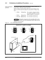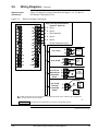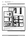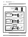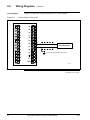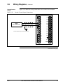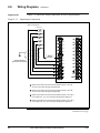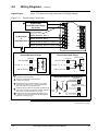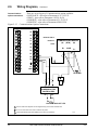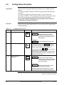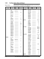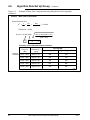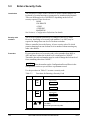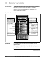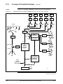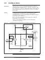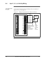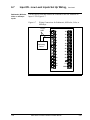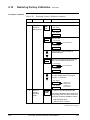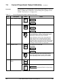
1
UDC 6300 Process Controller Product Manual 51-52-25-45 1/03 Rev. C Industrial Measurement and Control Copyright, Notices, and Trademarks Printed in U.S.A. – © Copyright 1999 by Honeywell Inc. Rev. C While this information is presented in good faith and believed to be accurate, Honeywell disclaims the implied warranties of merchantability and fitness for a particular purpose and makes no express warranties except as may be stated in its written agreement with and for its customer. In no event is Honeywell liable to anyone for any indirect, special or consequential damages. The information and specifications in this document are subject to change without notice. This document was prepared using Information Mapping® methodologies and formatting principles. UDC 6300 is a trademark of Honeywell Inc. Information Mapping is a trademark of Information Mapping Inc. Industrial Measurement and Control Honeywell Inc. 1100 Virginia Drive Fort Washington, PA 19034 ii UDC 6300 Process Controller Product Manual 1/03 About This Publication How this manual is organized This Product Manual is divided into 11 sections. These sections contain all the information you need to configure, operate, monitor, and troubleshoot your controller. To find information quickly, use the comprehensive Table of Contents in the front of the manual and the Index located in the back of the manual. Warranty The device described herein has been manufactured and tested for correct operation and is warranted as follows: The Process Controller carries an 18 month warranty. This warranty includes immediate technical assistance via a toll free telephone number and complete replacement of the controller, if necessary. Contacts World Wide Web The following lists Honeywell’s World Wide Web sites that will be of interest to our industrial automation and control customers. Honeywell Organization WWW Address (URL) Corporate http://www.honeywell.com Industrial Measurement and Control http://www.honeywell.com/imc International http://www.honeywell.com/Business/global.asp Telephone Contact us by telephone at the numbers listed below. Organization Phone Number United States and Canada Honeywell Inc. 1-800-423-9883 1-800-525-7439 Asia Pacific Honeywell Asia Pacific Inc. Hong Kong (852) 2829-8298 Europe Honeywell PACE, Brussels, Belgium [32-2] 728-2111 Latin America Honeywell Inc., Sunrise, Florida U.S.A. (954) 845-2600 1/03 UDC 6300 Process Controller Product Manual Tech. Support Service iii Symbol Definitions ! This CAUTION symbol on the equipment refers the user to the Product Manual for additional information. This symbol appears next to required information in the manual. WARNING, risk of electric shock. This symbol warns the user of a potential shock hazard where HAZARDOUS LIVE voltages greater than 30 Vrms, 42.4 Vpeak, or 60 Vdc may be accessible. Protective earth terminal. Provided for connection of the protective earth (green or green/yellow) supply system conductor. iv UDC 6300 Process Controller Product Manual 1/03 Table of Contents SECTION 1 – OVERVIEW.................................................................................................. 1 1.1 Introduction................................................................................................... 1 1.2 Operator Interface ........................................................................................ 4 SECTION 2 – INSTALLATION........................................................................................... 7 2.1 2.2 2.3 2.4 2.5 2.6 Overview....................................................................................................... 7 Model Number Interpretation........................................................................ 9 Preliminary Installation Procedure .............................................................10 Mounting.....................................................................................................13 Wiring .........................................................................................................15 Wiring Diagrams .........................................................................................17 SECTION 3 – CONFIGURATION.....................................................................................27 3.1 Overview.....................................................................................................27 3.2 Configuration Prompts................................................................................28 3.3 How To Get Started....................................................................................30 3.4 Configuration Tips ......................................................................................31 3.5 Configuration Procedure ............................................................................32 3.6 Tuning Parameters Set Up Group..............................................................34 3.7 Tuning L2 Parameters Set Up Group (Cascade or 2 Loop) ......................37 3.8 SP Ramp/Program Set Up Group ..............................................................39 3.9 Accutune Set Up Group .............................................................................40 3.10 Algorithm Data Set Up Group ...................................................................42 3.11 Advanced Math Parameters Set Up Group ..............................................48 3.12 Output Algorithm Parameters Set Up Group ............................................51 3.13 Input 1 Through 4 Parameters Set Up Group...........................................52 3.14 Input 5 Parameters Set Up Group ............................................................53 3.15 Loop 1 Control Parameters Set Up Group ...............................................54 3.16 Loop 2 Control Parameters Set Up Group ...............................................56 3.17 Options Set Up Group ..............................................................................58 3.18 Communications Group ............................................................................60 3.19 Alarms Set Up Group................................................................................62 3.20 Display Parameters Set Up Group ...........................................................65 3.21 Calib Group...............................................................................................66 3.22 Status Group.............................................................................................66 3.23 Configuration Record Sheet .....................................................................67 SECTION 4 – CONFIGURATION PROMPT DEFINITIONS ............................................71 4.1 Overview.....................................................................................................71 4.2 Tuning Parameters Set Up Group..............................................................72 4.3 Tuning Loop 2 Parameters Set Up Group..................................................76 4.4 Setpoint Ramp/Rate Set Up Group ............................................................77 4.5 Accutune Set Up Group .............................................................................79 4.6 Algorithm Data Set Up Group.....................................................................82 4.7 Advanced Math Parameters Set Up Group................................................98 4.8 Output Algorithm Parameters Set Up Group............................................104 4.9 Input 1 Through 4 Parameters Set Up Group ..........................................106 4.10 Input 5 Parameters Set Up Group ..........................................................108 4.11 Control Parameters Set Up Group..........................................................111 4.12 Control2 Parameters Set Up Group .......................................................116 4.13 Options Set Up Group ............................................................................120 4.14 Communications Set Up Group ..............................................................128 4.15 Alarms Set Up Group..............................................................................133 Table of Contents, continued 1/03 UDC 6300 Process Controller Product Manual v 4.16 Display Parameters Set Up Group ......................................................... 138 4.17 Calibration Data ...................................................................................... 141 4.18 Status Test Data ..................................................................................... 141 SECTION 5 – OPERATION............................................................................................ 143 5.1 Overview .................................................................................................. 143 5.2 How to Power Up The Controller ............................................................. 144 5.3 Enter a Security Code .............................................................................. 146 5.4 Monitoring Your Controller ....................................................................... 147 5.5 Start Up Procedure................................................................................... 153 5.6 Operating Modes...................................................................................... 154 5.7 Setpoints .................................................................................................. 158 5.8 Setpoint Rate............................................................................................ 165 5.9 Single Setpoint Ramp............................................................................... 166 5.10 Using Two Set of Tuning Constants ....................................................... 169 5.11 2 Loops of Control Overview .................................................................. 172 5.12 Configure 2 Loop of Control ................................................................... 177 5.13 Monitor 2 Loops of Control ..................................................................... 180 5.14 Operate 2 Loops of Control .................................................................... 183 5.15 Input Math Algorithms............................................................................. 184 5.16 Logic Gate Operation.............................................................................. 187 5.17 Digital Outputs ........................................................................................ 189 5.18 Digital Input Option (Remote Switching)................................................. 192 5.19 Fuzzy Overshoot Suppression ............................................................... 198 5.20 Accutune™ ............................................................................................. 199 5.21 Input 5 - Pulse Input................................................................................ 208 5.22 Three Position Step Control ................................................................... 210 5.23 Auto/Manual Station ............................................................................... 212 SECTION 6 – INPUT CALIBRATION ............................................................................ 217 6.1 Overview .................................................................................................. 217 6.2 Minimum and Maximum Range Values ................................................... 218 6.3 Input 1, 2, 3, or 4 Preliminary Information ................................................ 219 6.4 Input 1, 2, 3, or 4 Set Up Wiring............................................................... 221 6.5 Input #1, 2, 3, or 4 Calibration Procedure ................................................ 222 6.6 Input 5 - Low Level Inputs Preliminary Information.................................. 224 6.7 Input #5 - Low Level Inputs Set Up Wiring............................................... 226 6.8 Input #5 - Low Level Inputs Calibration Procedure .................................. 230 6.9 Input #5 - Pulse Input Preliminary Information......................................... 232 6.10 Input #5 - Pulse Input Calibration Procedure ......................................... 233 6.11 Input #5 - Pulse Input Verification........................................................... 235 6.12 Restoring Factory Calibration ................................................................. 236 SECTION 7 – OUTPUT CALIBRATION ........................................................................ 241 7.1 Overview .................................................................................................. 241 7.2 Current Proportional Output Calibration................................................... 242 7.3 2nd Current Output................................................................................... 245 SECTION 8 – TROUBLESHOOTING / SERVICE ......................................................... 249 8.1 8.2 8.3 8.4 8.5 8.6 Overview .................................................................................................. 249 Troubleshooting Aids ............................................................................... 251 Power-up Tests ........................................................................................ 253 Status Tests ............................................................................................. 254 Background Tests .................................................................................... 257 Controller Failure Symptoms.................................................................... 259 Table of Contents, continued 8.7 Troubleshooting Procedures .................................................................... 260 vi UDC 6300 Process Controller Product Manual 1/03 8.8 Parts Replacement Procedures ...............................................................266 8.9 Maintenance .............................................................................................277 SECTION 9 – PARTS LIST ............................................................................................279 9.1 Exploded View..........................................................................................279 1/03 UDC 6300 Process Controller Product Manual vii Figures Figure 1-1 Operator Interface Displays and Indicators............................................................. 4 Figure 2-1 Model Number Interpretation .................................................................................. 9 Figure 2-2 Power Select Jumper Placement .......................................................................... 11 Figure 2-3 Dimensions............................................................................................................ 13 Figure 2-4 Composite Wiring Diagram ................................................................................... 17 Figure 2-5 Line Voltage Wiring ............................................................................................... 18 Figure 2-6 High Level Input Connections ............................................................................... 19 Figure 2-7 Optional Input 5, Low level Input Connections...................................................... 20 Figure 2-8 Optional Input 5-Pulse Input Connections ............................................................ 21 Figure 2-9 Current Output Connections ................................................................................. 22 Figure 2-10 Second Current Output Connections .................................................................... 23 Figure 2-11 Digital Input Connections ...................................................................................... 24 Figure 2-12 Digital Output Connections ................................................................................... 25 Figure 2-13 Communications Option Connections................................................................... 26 Figure 3-1 Overview of UDC6300 Prompt Hierarchy ............................................................. 28 Figure 4-1 Example of Mass Flow Compensation using Multiplier/Divider Algorithm............ 95 Figure 4-2 Example of Eight Segment Characterizer............................................................. 97 Figure 5-1 Operator Interface ............................................................................................... 147 Figure 5-2 Functional Overview Block Diagram of a Single Loop Controller - Loop #1...... 173 Figure 5-3 Functional Overview Block Diagram of Loop 2 of a 2 Loop Controller ............... 174 Figure 5-4 Functional Overview Block Diagram of Internal Cascade of a 2 Loop Controller175 Figure 5-5 Hi/Lo Override Selector....................................................................................... 176 Figure 5-5 Auto/Manual Station Using Digital Input #1 and Backup Control Feature .......... 212 Figure 6-1 Input #1, 2, 3, or 4 Wiring Terminals ................................................................... 219 Figure 6-2 Wiring Connections for 1 to 5 Volts or 4 to 20 mA .............................................. 221 Figure 6-3 Input #5 - Low Level Inputs Wiring Terminals..................................................... 224 Figure 6-4 Wiring Connections for Thermocouple Inputs Using an Ice Bath ....................... 226 Figure 6-5 Wiring Connections for Thermocouple Inputs Using a Precision Resistor ......... 227 Figure 6-6 Wiring Connections for RTD (Resistance Thermometer Device) ....................... 228 Figure 6-7 Wiring Connections for Radiamatic, Millivolts, Volts, or Milliamps...................... 229 Figure 6-8 Test Equipment connections for Calibrating Pulse Inputs .................................. 235 Figure 7-1 Wiring Connections for Calibrating Current Proportional Output........................ 243 Figure 7-2 Wiring Connections for Calibrating 2nd Current Output ..................................... 246 Figure 8-1 Chassis Removal ................................................................................................ 267 Figure 8-3 Bezel/Keyboard/Display Assembly ..................................................................... 270 Figure 8-4 Keyboard and Display Board Removal ............................................................... 270 Figure 8-2 Replacement Parts Identification ........................................................................ 268 Figure 8-5 Printed Wiring Board Identification...................................................................... 271 Figure 8-6 Power Select Jumper Location ........................................................................... 273 Figure 9-1 UDC 6300 Exploded View................................................................................... 279 viii UDC 6300 Process Controller Product Manual 1/03 Tables Table 1-1 Table 2-1 Table 2-2 Table 2-3 Table 2-4 Table 3-1 Table 3-2 Table 3-3 Table 3-4 Table 3-5 Table 3-6 Table 3-7 Table 3-8 Table 3-9 Table 3-10 Table 3-11 Table 3-12 Table 3-13 Table 3-14 Table 3-15 Table 3-16 Table 3-17 Table 4-1 Table 4-2 Table 4-3 Table 4-4 Table 4-5 Table 4-6 Table 4-7 Table 4-8 Table 4-9 Table 4-10 Table 4-11 Table 4-12 Table 4-13 Table 4-14 Table 4-15 Table 4-16 Table 5-1 Table 5-2 Table 5-3 Table 5-4 Table 5-5 Table 5-6 Table 5-7 Table 5-8 Table 5-9 Table 5-10 Table 5-11 Table 5-12 Table 5-13 Function of Keys........................................................................................... 5 Operating Limits ........................................................................................... 8 Preliminary Installation Procedure .............................................................10 Mounting Procedure ...................................................................................14 Permissible Wiring Bundling.......................................................................15 Configuration Tips ......................................................................................31 Configuration Procedure ............................................................................32 Tuning Group Function Prompts ................................................................35 Tuning L2 Group Function Prompts ...........................................................37 SP Ramp Group Function Prompts............................................................39 Accutune Group Function Prompts ............................................................41 Algorithm Group Function Prompts............................................................42 Advanced Math Group Function Prompts ..................................................48 Output Algorithm Group Function Prompts ................................................51 Input 1 through 4 Set Up Groups Function Prompts..................................52 Input 5 Group Function Prompts ................................................................53 Control Group Function Prompts ...............................................................54 Control2 Group Function Prompts .............................................................56 Options Group Function Prompts...............................................................58 Commun Group Function Prompts ............................................................60 Alarms Group Function Prompts ................................................................62 Display Group Function Prompts ...............................................................65 Tuning Group Prompt Definitions ...............................................................72 Tuning L2 (Loop 2) Group Prompt Definitions ..........................................76 Setpoint Ramp/Rate Group Definitions ......................................................77 Accutune Group Definitions........................................................................79 Algorithm Group Definitions .......................................................................82 Advanced Math Group Definitions .............................................................98 Output Algorithm Group Definitions .........................................................104 Input 1 through 4 Group Definitions .........................................................106 Input 5 Group Definitions..........................................................................108 Control Group Definitions .........................................................................111 Control2 Group Definitions .......................................................................116 Option Group Definitions ..........................................................................120 Communications Group Definitions..........................................................128 Alarms Group Definitions .........................................................................133 Latching and Non-latching Alarm Configuration ......................................137 Display Group Definitions.........................................................................138 Power Up Diagnostic Tests ......................................................................144 Procedure for Testing the Displays and Keys ..........................................145 Procedure for Entering a Security Code ..................................................146 Lower Display Key Parameter Prompts ...................................................150 Error Messages ........................................................................................152 Procedure for Starting Up the Controller..................................................153 Operating Mode Definitions......................................................................154 Changing Operating Modes .....................................................................155 Procedure for Selecting Automatic or Manual Mode ...............................156 Procedure for Selecting the Local Setpoint Source .................................158 Procedure for Changing the Local Setpoints ...........................................159 Procedure for Switching Between Local Setpoint 1 and 2 .......................160 Procedure for Switching Between Local Setpoint 3 and Local Setpoint 1 or 2......................................................................................161 Table 5-14 Procedure for Selecting the Remote Setpoint Source .............................162 Table 5-15 Procedure for Switching Between Local and Remote Setpoints ............163 Table 5-16 Setpoint Selection Indication ....................................................................164 Tables, continued 1/03 UDC 6300 Process Controller Product Manual ix Table 5-17 Table 5-18 Table 5-19 Table 5-20 Table 5-21 Table 5-22 Table 5-23 Table 5-24 Table 5-25 Table 5-26 Table 5-27 Table 5-28 Table 5-29 Table 5-30 Table 5-31 Table 5-32 Table 5-33 Table 5-34 Table 5-35 Table 5-36 Table 5-37 Table 5-38 Table 5-39 Table 5-40 Table 5-41 Table 5-42 Table 5-43 Table 5-44 Table 5-45 Table 5-46 Table 6-1 Table 6-10 Table 6-2 Table 6-3 Table 6-4 Table 6-5 Table 6-6 Procedure for Configuring a Setpoint Ramp ............................................ 166 Procedure for Running a Setpoint Ramp ................................................. 167 Procedure for Selecting Two Set of Tuning Constants............................ 169 Procedure for Setting Switchover Values ................................................ 170 Procedure for Setting Tuning Constant Values........................................ 170 Procedure for switching PID SETS from the Keyboard ........................... 171 Control Loop Selections ........................................................................... 172 Procedure for Selecting 2 Loop Algorithm ............................................... 177 Procedure for Selecting Output Algorithm ............................................... 177 Procedure for Selecting Control Parameters ........................................... 178 Procedure for Selecting Tuning Parameters............................................ 179 Digital Display Indication - 2 Loops ......................................................... 180 Bargraph Indication - 2 Loops ................................................................. 181 Logic Gates Constraints and Dynamic Operation Status ....................... 188 Latching and Non-Latching Alarm Operation........................................... 189 Digital Input 1 and 2 Option Action on Contact Closure .......................... 192 Digital Input Combinations “DIG IN 1”...................................................... 194 Digital Input Combinations “DIG IN 2”...................................................... 194 Digital Input 1 and 2 Combination Operation ........................................... 195 Digital Input 3, 4, 5, 6 Option Action on Contact Closure ........................ 196 Accutune Rules and Regulations ............................................................. 200 Procedure for Starting TUNE (Demand) Tuning ...................................... 201 Procedure for Using TUNE at Start-up for Duplex ................................... 202 Procedure for Using SP Only Tuning at Start-up ..................................... 203 Procedure for Using SP Tuning at Start-up for Duplex............................ 204 Adaptive Tune Error Prompt Definitions .................................................. 207 Controller Configuration Selections for Pulse Input ................................. 209 Procedure for Setting the 3PSTEP Motor time ........................................ 210 Procedure for Displaying the 3PSTEP Motor Position............................. 211 Auto/Manual Station Mode Configuration Procedure .............................. 214 Voltage and Resistance Equivalents for 0% and 100% Range Values... 218 Restoring Factory Calibration................................................................... 236 Equipment Needed................................................................................... 220 Input #1, 2, 3, or 4 Calibration Procedure ................................................ 222 Equipment Needed................................................................................... 225 Set Up Wiring Procedure for Thermocouple Inputs Using An Ice Bath .. 226 Set Up Wiring Procedure for Thermocouple Inputs Using a Precision Resistor.................................................................................................. 227 Table 6-7 Input #5 Calibration Procedure ................................................................ 230 Table 6-8 Input #5 - Pulse Input Calibration Procedure ........................................... 233 Table 6-9 Pulse Input Verification Setup .................................................................. 235 Table 7-1 Set Up Wiring Procedure Current Proportional Output............................ 242 Table 7-2 Current Proportional Output Calibration Procedure................................. 244 Table 7-3 Set Up Wiring Procedure for 2nd Current Output .................................... 245 Table 7-4 2nd Current Output Calibration Procedure .............................................. 247 Table 8-1 Error Message Prompts ........................................................................... 251 Table 8-2 Procedure for Identifying the Software Version ....................................... 252 Table 8-4 Procedure for Displaying the Status Tests Results ................................. 254 Table 8-5 Status Tests ............................................................................................. 255 Table 8-6 Background Tests .................................................................................... 257 Table 8-7 Controller Failure Symptoms.................................................................... 259 Table 8-8 Troubleshooting Power Failure Symptoms .............................................. 260 Table 8-9 Troubleshooting Current Proportional Output Failure.............................. 261 Table 8-10 Troubleshooting Time Proportional Digital Output(s) Failure................... 262 Table 8-11 Troubleshooting Alarm Digital Output(s) Failure...................................... 263 Table 8-12 Troubleshooting a Keyboard Failure........................................................ 264 Tables, continued Table 8-13 Troubleshooting a DMCS Communications Failure................................. 265 x UDC 6300 Process Controller Product Manual 1/03 Table 8-14 Table 8-15 Table 8-16 Table 8-17 Table 8-18 Table 8-19 Table 8-20 Table 9-1 Table 9-2 Table 9-3 1/03 How to Remove the Chassis ....................................................................267 Bezel/Keyboard/Display Assembly Replacement Procedure ..................269 Access the Printed Wiring Boards............................................................271 MCU/Inputs PWB Replacement Procedure .............................................272 Communications Option Board Replacement Procedure ........................274 Digital I/O PWB Replacement Procedure ................................................275 Option Input Board Replacement Procedure ...........................................276 Parts Identification ....................................................................................280 Parts Not Shown.......................................................................................281 Gray Vutronik Mask Kits...........................................................................281 UDC 6300 Process Controller Product Manual xi Acronyms 3PSTEP............................................................................................ 3 Position Step Control EMI ..........................................................................................Electromagnetic interference HID .................................................................................................. high intensity discharge MOVs ................................................................................................. Metal Oxide Varistors PID ............................................................................. Proportional, Integral, and Derivative RC ....................................................................................................resistance-capacitance RFI.......................................................................................... Radio frequency interference RH .............................................................................................................Relative Humidity RTD .................................................................................. Resistance Thermometer Device SCRs ...........................................................................................Silicon controlled rectifiers UDC......................................................................................................... Process Controller xii UDC 6300 Process Controller Product Manual 1/03 References Publication Title Publication Number UDC3000/UDC5000/UDC6000/UDC6300 RS422/485 Communications Option Manual 51-51-25-35 UDC6300 MODBUS 485RTU Communications Option manual 51-51-25-53 PM/APM UDC6300 Integration Manual 1/03 UDC 6300 Process Controller Product Manual PM12-520 xiii xiv UDC 6300 Process Controller Product Manual 1/03 Section 1 – Overview 1.1 Introduction Function The UDC 6300 Process Controller is a microprocessor-based controller that handles basic control strategies and is easily upgraded to higher functionality to meet advanced control strategies such as 2 Loops of control, Cascade, Feedforward control or those requiring logic or math functions. The controller has four high-level, and an optional low level, isolated loop related analog input signals. The controller produces current outputs and four Digital Outputs or Digital Inputs based on operator-entered data plus two more dedicated Digital Inputs. See the block diagrams for: • One loop of control - Figure 5-2 • Two loops of control - Figure 5-3 • Internal Cascade control - Figure 5-4 CE Conformity (Europe) This product is in conformity with the protection requirements of the following European Council Directives: 73/23/EEC, the Low Voltage Directive, and 89/336/EEC, the EMC Directive. Conformity of this product with any other “CE Mark” Directive(s) shall not be assumed. Deviation from the installation conditions specified in this manual, and the special conditions for CE conformity in Section 2.1, may invalidate this product’s conformity with the Low Voltage and EMC Directives. ATTENTION The emission limits of EN 50081-2 are designed to provide reasonable protection against harmful interference when this equipment is operated in an industrial environment. Operation of this equipment in a residential area may cause harmful interference. This equipment generates, uses, and can radiate radio frequency energy and may cause interference to radio and television reception when the equipment is used closer than 30 meters (98 feet) to the antenna(e). In special cases, when highly susceptible apparatus is used in close proximity, the user may have to employ additional mitigating measures to further reduce the electromagnetic emissions of this equipment. Continued on next page 1/03 UDC 6300 Process Controller Product Manual 1 1.1 Introduction, Continued Inputs Four high-level inputs are standard. They can be: • 1 to 5 Volts, • 4 to 20 mA, or • 10 to 50 mA A fifth input is available as an option and can be one of several types: • a low-level Thermocouple or RTD sensor • a linear input (mA, Volts, mV, or Radiamatic) • a pulse counter input for use with frequency output devices. This Pulse counter input can be used as a frequency input or as a setpoint adjustment input whereby each pulse is counted as one least significant digit change to the setpoint. A digital input selection determines the direction of setpoint change. Any input can be used as: • the process variable for either loop • remote setpoint signal • for computing the weighted average of two inputs • Input for Math algorithms such as feedforward Summer or Multiplier, Input Summing with Ratio and Bias, HI/LO Input Select with Ratio and Bias, Multiplier/Divider. Outputs The controller has a current output and is available with an optional second current output for control, or a signal representing any of several controller parameters for control or recording purposes. Output Algorithms Depending on how many loops you configure, the UDC6300 is available with various preselected output algorithms including: • On/Off, • On/Off Duplex, • Time Proportional Simplex or Duplex, • Current Proportional Simplex or Duplex, • Current/Time Duplex. Digital Inputs / Outputs Four points, each of which can be an open-collector type Digital Output for alarm and control, or a Digital Input. There are also two dedicated Digital Inputs. Continued on next page 2 UDC 6300 Process Controller Product Manual 1/03 1.1 Introduction, Continued Control Algorithms Depending on the Control output type specified, the controller can be configured for the following control algorithms: • On/Off control, • PID-A Equation, • PID-B Equation, • PD with Manual Reset. • 3 Position Step Control Duplex control can be configured for all algorithms except 3 Pos Step. Options Available options include: Dual Loop / Internal Cascade Two independent loops of control or internal cascade linking of the primary and secondary controller in one device. Includes output override algorithm. Accutune Automatically adjusts the PID tuning parameters as necessary while controlling at setpoint in the automatic control mode. Second Current Output Fully isolated and configurable as control output or auxiliary output Transmitter Power 24Vdc power to supply one or two, 4 to 20mA transmitters for the high level inputs. Communications Serial communications link integrates with CRT-based RS422/485 or DMCS. Math Options Two pre-configured algorithms have easy implementation into either control loop. They can be linked or used individually and are capable of using any input with its’ Ratio and Bias. Gain Scheduling - 8 Gain values may be applied to 8 Process Variable (PV) bands for use on known non-linear processes. Two 8-Segment Characterizers - can be applied to Input 2, Input 4, Loop 1 Output, or Loop 2 Output. Polynomial Curve Characterizer-- a fifth order polynomial equation can be used on any one of the five analog inputs. Totalizer Function - displays actual current totalized value of up to 8 digits. Digital Logic Gates - up to 5 gates can be configured. For each gate you can select from 8 gate types; each gate having two input sources and one output use. 1/03 UDC 6300 Process Controller Product Manual 3 1.2 Operator Interface Displays and indicators Figure 1-1 Figure 1-1 shows the operator interface and defines the displays and indicators. The function of the keys is shown in Table 1-1. Operator Interface Displays and Indicators PV SP Upper display – nine characters • Normal Operation: displays the process variable (4 digits) • Configuration Mode: displays parameter value or selection 6300 6300 Lower display – nine characters • Normal Operation: displays operating parameters and values or I.D. tag • Configuration Mode: displays function groups and parameters 100 °F °C Three bargraphs, each containing 81 discrete bars plus two arrows, are used to display: 80 Annunciators – illuminate as appropriate L12 °F°C = Temperature units bein displayed L12 = Loop display indication CAS = Cascade mode SP23 = Indicates local setpoint being used RSP = Remote setpoint being used CSP = Computer setpoint MAN = Manual control mode AUTO= Automatic control mod 1234 = Indicates digital output alarm conditions CAS 60 Setpoint SP23 RSP 40 Process variable CSP MAN 20 Output AUTO Bargraphs and alarm annunciators flash on alarm condition until acknowledged 0 SP 1234 PV O FUNC LOWR MAN L1/L2 DISP AUTO SET UP RSP CAS SP1 SP2 ALM ACK 21742 Continued on next page 4 UDC 6300 Process Controller Product Manual 1/03 1.2 Operator Interface, Function of keys Continued Table 1-1 shows each key on the operator interface and defines its function. Table 1-1 Function of Keys Key SET UP Function • Places the controller in the Configuration Set Up group select mode. Sequentially displays Set Up groups and allows the FUNC key to display individual functions in each Set Up group. • A manual check of all the displays can be invoked. Press the SET UP key and hold in, then press FUNC key. All segments of the displays will be illuminated. FUNC L1/L2 • Used in conjunction with the SET UP key to select the individual functions of a selected Configuration Set Up group. • Press the FUNC key and key to start/halt setpoint ramp • Also toggles between Loop 1 and Loop 2 display. LOWR DISP • Selects any one of 26 operating parameter to be shown in the lower display. See subsection 5.4 for list. • Used to exit Set Up. MAN AUTO RSP CAS • Alternately selects: AUTO Lower display automatically displays setpoint value in engineering units. MAN Lower display automatically indicates output in %. • Alternately selects Local Setpoint 1 and Remote Setpoint or Local Setpoint 3. • Changes the controller from local to remote and vice versa. • Also, switches into or out of Internal Cascade Control. SP1 SP2 ALM ACK • Toggles between Local Setpoint #1 and #2. • Press to acknowledge new alarm condition and stop bargraph flashing. • Provides direct access to alarm group. • Increases the setpoint, output, or configuration values displayed. The value displayed is entered by advancing to the next display. • Decreases the setpoint, output, or configuration values displayed. The value displayed is entered by advancing to the next display. 1/03 UDC 6300 Process Controller Product Manual 5 6 UDC 6300 Process Controller Product Manual 1/03 Section 2 – Installation 2.1 Overview Introduction Installation of the controller consists of mounting and wiring the controller according to the instructions given in this section. The Process Controller is industrial control equipment that must be panel mounted. The wiring terminals must be enclosed within the panel. Read the pre-installation information, check the model number interpretation and become familiar with your model selections, then proceed with installation. What’s in this section? This section contains the following information: Topic Controller Replacement See Page 2.1 Overview 7 2.2 Model Number Interpretation 9 2.3 Preliminary Installation Procedure 10 2.4 Mounting 13 2.5 Wiring 15 2.6 Wiring Diagrams 17 If you are replacing a UDC6000 or an existing UDC6300 you can keep the old configuration data by removing the EEPROM from the old unit and placing it in the new unit. Refer to Subsection 8.8 for location of the EEPROM and instructions. Continued on next page 1/03 UDC 6300 Process Controller Product Manual 7 2.1 Overview, Continued Pre-installation information If the controller has not been removed from its shipping carton, inspect the carton for damage and remove the controller. Inspect the unit for any obvious shipping damage and report any damage due to transit to the carrier. Make sure a bag containing mounting hardware is included in the carton with the controller. Check that the model number shown on the inside of the case agrees with what you have ordered. CE Conformity special conditions (Europe) Shielded twisted pair cables are required for all Analog I/O, Process Variable, RTD, Thermocouple, dc millivolt, low level signal, 4-20 mA, Digital I/O, and computer interface circuits. For performance Criterion A under special conditions, DO NOT set alarm outputs to LATCHING (ref. Sections 3.19, 4.15, and 5.17) Refer to Appendix B - Severe Electrical Noise Environments for additional installation guidance. Operating limits We recommend that you review and adhere to the operating limits listed in Table 2-1 when you install your controller. Table 2-1 Operating Limits Condition Ambient Temperature 32 to 140°F (0 to 60°C) Relative Humidity 5 to 90% RH at 40°C (104°F) Vibration Frequency Acceleration 0 to 200Hz 0.2g Mechanical Shock Acceleration Duration 5g 30ms Power Voltage Frequency(Hz) 8 Specifications 20 to 30 Vac/dc 96 to 132 Vac 192 to 264 Vac 49 to 51 59 to 61 Transmitter Supply Voltage (at input terminals) 22 to 26 Vdc @ 50mA Power Consumption 20VA Maximum UDC 6300 Process Controller Product Manual 1/03 2.2 Model Number Interpretation The model number interpretation is shown in Figure 2-1. Write the model number into the spaces provided and compare it to the model number interpretation. This information will also be useful when you wire your controller. Model number Figure 2-1 Model Number Interpretation Key Number Table I Table II Table III Table IV PC 6 30 0 Product Manual Key Number E F G Controller PC6301Standard I/O(4 Inputs + 1 Current Output) PC6302Standard I/O and Digital I/O* PC6303Standard I/O, Digital I/O *and Second Current Output Indicator PC63044 Inputs Only PC63054 Inputs + Digital I/O* PC63064 Inputs + Digital I/O *+ Auxiliary Current Output Power S 24 Vac/dc Only U 24 Vac/dc, / 115 Vac / 230 Vac (Universal) Communications 0__ 1__ 2__ 3__ 4__ Software Options _ 0 _ None _ A _ Adaptive Tuning (A/T) _ B _ Math Algorithms + A/T _ C _ 2 Loops/Cascade + A/T _ D _ 2 Loops/Cascade + A/T + Math Alg. Options O T C F A B D E None Customer ID Tag CSA Approved* Factory Mutual Class 1, Div. 2 Appro FM and CSA Certified* FM, CSA and Customer ID Tag* FM and Customer ID Tag* CSA and Customer ID Tag* *Pending 0 None 1 Thermocouple 2 RTD, Honeywell Radiamatic (RH Millivolts, or 1 to 5 Volts 3 0 to 10 Volts dc 5 4 to 20 Milliamps dc 6 10 to 50 mA 7 Pulse Input Transmitter Power 1/03 English French German Optional Input (Qty 1) None DMCS RS422/485 ASCII TPS Integration MODBUS 485 RTU _ _ 0 None _ _ P 2 Inputs Maximum Table V Standard Inputs (Qty 4) 4 _ 1 to 5 Vdc 5 _ 4 to 20 mA 6 _ 10 to 50 mA 23037 * Digital I/O provides 2 DI's + 4 Universal DI/DO's UDC 6300 Process Controller Product Manual 9 2.3 Preliminary Installation Procedure Introduction Before you install the controller, you must check your Input Range selection (standard and optional). Procedure Two power select jumpers are supplied with the controller are supplied with the controller. Refer to Figure 2-2 for jumper location and follow the procedure in Table 2-2 to install them. Table 2-2 Preliminary Installation Procedure Step Action 1 Loosen the front screw and pull the chassis out of the case. 2 Lay the chassis on a non-conductive surface. 3 Install the two power select jumpers, supplied with the kit, into the correct position on the MCU/Input printed wiring board. See Figure 2-2 for the correct position for the Voltage being used. 4 Replace the controller chassis into the case and tighten the screw. Continued on next page 10 UDC 6300 Process Controller Product Manual 1/03 2.3 Preliminary Installation Procedure, Power select jumper placement Continued This controller requires a specific fuse and power jumper position if its model number is DC630X-U-XXX-XX-X-XX. Figure 2-2 shows you the locations of the Power Select Jumper. It also shows you where to place the jumper for your particular Voltage being used. • 115 Vac 315 mA Fuse The controller is shipped with this fuse installed and the Power Select jumper set in the 115 Vac position. • 230 Vac 200 mA Fuse Fuse included in separate bag. • 24 Vac/dc 800 mA Fuse Fuse included in separate bag. CAUTION Applying the wrong power to the controller will severely Figure 2-2 damage the controller and is a fire and smoke hazard. Make sure the jumpers are set correctly. Power Select Jumper Placement POWER SELECT JUMPER PLACEMENT 24Vac/dc 115 Vac 230 Vac 230Vac 230Vac 230Vac 230Vac 230Vac 230Vac 115Vac 115Vac 115Vac 115Vac 115Vac 115Vac 24V 24V PWR SEL 24V 24V 24V PWR SEL 24V PWR SEL MCU/Input Board Power Select Jumpers 230Vac 230Vac 115Vac 115Vac 24V 24V PWR SEL Front Screw 23038 Continued on next page 1/03 UDC 6300 Process Controller Product Manual 11 2.3 Preliminary Installation Procedure, Continued Standard inputs range selection (Inputs 1 through 4) The controller will be shipped set up for a range of 1 to 5 Volts. If a 4 to 20 or 10 to 50 mA was specified (ordered), a kit of 5 resistors for the appropriate range will be included in the shipping box. These must be attached to the proper terminals as shown in Figure 2-6. The kit numbers are: 4 to 20 mA Kit # 30755498-001 (250 Ohm Resistor) 10 to 50 mA Kit # 30755498-002 (100 Ohm Resistor) Optional input 5 range selection (Low Level Input) If an Input 5 - Low Level is ordered, kits will be supplied containing: •A Cold Junction Resistor for Thermocouple ranges Kit # 30757088-501 •A Voltage Divider Assembly for 0 to 10 Volt ranges Kit # 30754465-001 •A 250 ohm Precision Resistor for 4 to 20 mA ranges Kit # 30755498-001 •A 100 ohm Precision Resistor for 10 to 50 mA ranges Kit # 30755498002 Attach the resistor for your specific range to the Input 5 terminals as shown in Figure 2-7. Electrical considerations The controller is considered “rack and panel mounted equipment” per EN 61010-1, Safety Requirements for Electrical Equipment for Measurement, Control, and Laboratory Use, Part 1: General Requirements. Conformity with 72/23/EEC, the Low Voltage Directive requires the user to provide adequate protection against a shock hazard. The user shall install this controller in an enclosure that limits OPERATOR access to the rear terminals. Controller grounding PROTECTIVE BONDING (grounding) of this controller and the enclosure in which it is installed shall be in accordance with National and local electrical codes. To minimize electrical noise and transients that may adversely affect the system, supplementary bonding of the controller enclosure to a local ground, using a No. 12 (4 mm2) copper conductor, is recommended. 12 UDC 6300 Process Controller Product Manual 1/03 2.4 Mounting The controller can be mounted on either a vertical or tilted panel using the mounting kit supplied. Adequate access space must be available at the back of the panel for installation and servicing activities. The overall dimensions and panel cutout requirements for mounting the controller are shown in Figure 2-3. Physical considerations Figure 2-3 shows the overall dimensions for mounting the controller. Dimensions Overall dimensions Figure 2-3 Dimensions: millimeters inches 144 5.67 33 1.31 max 72 2.83 Panel cutout (DIN standard) 68 2.68 138 5.43 +1.0 –0 +0.039 –0 +0.7 –0 +0.027 –0 233 max 9.19 25 1.00 Max. panel thickness Rear terminal cover NOTES: 1. Drawing is not to scale 2. No minimum horizontal spacing is defined. 3. Controller may be mounted at any angle or tilt. 23039 Continued on next page 1/03 UDC 6300 Process Controller Product Manual 13 2.4 Mounting, Continued Note Model Number Before mounting the controller, refer to the nameplate on the inside of the case and make a note of the model number. It will help later when selecting the proper wiring configuration. Mounting procedure Follow the procedure In Table 2-3 below to mount the controller. Table 2-3 Mounting Procedure Step 14 Action 1 Mark and cut out the controller hole in the panel according to the dimension information in Figure 2-3. There is no minimum horizontal spacing defined. Vertical spacing must be provided for access to the mounting kit brackets. 2 Remove the screw cover and loosen the screw on the front of the controller. Pull the chassis out of the case. 3 Orient the case properly and slide it through the panel hole from the front. 4 Remove the mounting kit (#30755050-001) from the shipping container, and install the kit as follows: • Install the screws into the threaded holes of the clips. • Insert the prongs of the clips into the two holes in the top and bottom of the case. • Tighten both screws to secure the case against the panel. • Carefully slide the chassis assembly into the case, press to close and tighten the screw. Replace the screw cover. 5 In addition to the mounting kit, a Rear Terminal Cover Kit (#30755496-001) is also provided. UDC 6300 Process Controller Product Manual 1/03 2.5 Wiring Taking electrical noise precautions Electrical noise is composed of unabated electrical signals which produce undesirable effects in measurements and control circuits. Digital equipment is especially sensitive to the effects of electrical noise. Your controller has built-in circuits to reduce the effect of electrical noise from various sources. If there is a need to further reduce these effects: • Separate External Wiring - separate connecting wires into bundles (see Table 2-4) and route the individual bundles through separate conduits or metal trays. • Use Suppression Devices - for additional noise protection, you may want to add suppression devices at the external source. Appropriate suppression devices are commercially available. NOTE Permissible wire bundling For additional noise information, refer to Appendix B. Table 2-4 shows which wire functions should be bundled together. Table 2-4 Permissible Wiring Bundling Bundle No. 1 Wire Functions • Line power wiring • Earth ground wiring • Control relay output wiring • Line voltage alarm wiring 2 Analog signal wire, such as: • Input signal wire (thermocouple, 4 to 20 mA, etc.) • 4-20mA output signal wiring • Slidewire feedback circuit wiring • Digital input signals • Communications 3 • Low voltage alarm relay output wiring • Low voltage wiring to solid state type control circuits Continued on next page 1/03 UDC 6300 Process Controller Product Manual 15 2.5 Wiring, Continued Identify your wiring requirements To determine the appropriate diagrams for wiring your controller, refer to the model number interpretation in this section. The model number of the controller contains selection codes that identify the Input/Output type, Standard Input Range, Optional 5th Input type, Software Options, and Optional selections. The model number of the controller can be found on the outside of the case and/or chassis. Wiring the controller Using the information contained in the model number, select the appropriate wiring diagrams from the figures listed below and wire the controller accordingly. Wiring Requirements 16 Figure Composite Wiring Diagram 2-4 AC Line Power 2-5 High Level Inputs - Inputs #1, #2, #3, #4 2-6 Optional Input 5 - Low Level Inputs 2-7 Optional Input 5 - Pulse Inputs 2-8 Current Output 2-9 Second Current Output 2-10 Digital Inputs 2-11 Digital Outputs 2-12 Communications Option 2-13 UDC 6300 Process Controller Product Manual 1/03 2.6 Wiring Diagrams Composite wiring diagram Figure 2-4 Figure 2-4 is a composite wiring diagram of the UDC6300 controller. It identifies the terminal designations and their functions. Refer to the individual diagrams listed to wire the controller according to your requirements. Composite Wiring Diagram Digital Output Customer Power Supply Terminals See Figure 2-12 Optional Input 5 Low Level Input Terminals See Figure 2-7 Pulse Input Terminals See Figure 2-8 2nd Current Output Terminals See Figure 2-10 Digital Inputs 1 & 2 Terminals See Figure 2-11 Digital Inputs and Outputs Terminals See Figures 2-11 & 2-12 1 14 High Level Inputs Terminals See Figure 2-6 14 + Input 1 2 15 15 + Input 2 3 16 16 – Signal Common 4 17 17 + Input 3 5 18 18 + Input 4 6 19 19 Internal Transmitter Power 7 20 8 21 9 22 10 23 Current Output Terminals See Figure 2-9 Communications Option Terminals See Figure 2-13 11 12 L1 13 L2/N Line Voltage Terminals See Figure 2-5 21749 Continued on next page 1/03 UDC 6300 Process Controller Product Manual 17 2.6 Wiring Diagrams, Line voltage wiring Continued This equipment is suitable for connection to 24Vac/dc or 115/230 Vac, 50/60 Hz, power supply mains. When connected to 115/230 Vac, 50/60 Hz, power supply mains, it is the user’s responsibility to provide a switch and slow-blow (North America), quick-acting, high breaking capacity, Type F, (Europe) 1/2 A, 250 V fuse(s) or circuit-breaker as part of the installation. The switch or circuit-breaker shall be located in close proximity to the controller, within easy reach of the OPERATOR. The switch or circuit-breaker shall be marked as the disconnecting device for the controller. CAUTION Applying the wrong power to the controller will severely Figure 2-5 damage the controller and is a fire and smoke hazard. Figure 2-5 shows the wiring connections for line voltage. Line Voltage Wiring 1 14 2 15 3 16 4 17 5 18 6 19 7 20 8 21 9 22 10 23 11 3 12 + L1 13 – L2/N HOT NEUTRAL "A" 1 4 23040 DC Line Voltage or AC Line Voltage 2 1 The Process controller and the enclosure in which it is mounted shall be grounded in accordance with National and Local electrical codes. Provide a switch and a slow-blow (North American), quick-acting, high breaking capacity, type F, (Europe) 2A fuse(s) for 24V (ac or dc) operation, and a 1/2 A, 250V fuse(s), or circuit breaker for 120/240 Vac operation, as part of this installation. 2 If power service has grounded neutral, connect lead "A" to neutral and omit the fuse in the neutral lead. 3 PROTECTIVE BONDING (grounding) of this controller and the enclosure in which it is installed shall be in accordance with National and local electrical codes. To minimize electrical noise and transients that may adversely affect the system, supplementary bonding of the controller enclosure to a local ground, using a No. 12 (4 mm2) copper conductor, is recommended. 4 Before applying power to the controller, set the power select jumpers on the MCU/Input PWB for the correct operating voltage. Continued on next page 18 UDC 6300 Process Controller Product Manual 1/03 2.6 Wiring Diagrams, High level input connections Figure 2-6 Continued Figure 2-6 shows the wiring connections for Input #1, #2, #3, and #4, also Internal Transmitter Power. High Level Input Connections 1 14 High Level Input Connections Inputs #1, #2, #3, #4 14 + Input 1 2 15 15 3 16 16 4 17 17 5 18 18 6 19 19 7 20 8 21 9 22 10 23 + – + + Input 2 Signal Common Input 3 Input 4 Internal Transmitter Power 1 to 5 Volts 11 12 L1 13 L2/N 10 to 50 mA + + 16 – + 16 + 4 to 20 mA External Transmitter Power 10 to 50mA source 100 Ω – 1 + 4 to 20 mA With Internal 16 Transmitter 19 Power 1 to 5 Volt source – 250 Ω + 16 1 2 Wire 4 to 20mA Transmitter + – 1 Xmitter + 250 Ω Power – + Supply 1 The 250Ω load resistor for the 4-20mA range or the 100Ω load resistor for the 10-50mA range is supplied with the controller when the input is specified. ATTENTION These items must be installed when you wire the controller before startup. 21751 Continued on next page 1/03 UDC 6300 Process Controller Product Manual 19 2.6 Wiring Diagrams, Figure 2-7 shows the wiring connections for Optional Input 5, Low Level Input. Optional Input 5 (Low Level Inputs) Figure 2-7 Continued Optional Input 5, Low level Input Connections Optional Input 5 Low Level Input Connections Use Thermocouple extension wire only Thermocouple 1 + 14 2 – 15 3 16 4 17 5 18 6 19 2 1 R + 3 – 2 1 R I N P U T 20 1R 5 10 to 50 mA Source 1 R RTD 2 + 3 – + – 100K 1 2 100K 3 100Ω – 2+ 3– 1R MV or Volt Source 0 –10 0–10 Volt Volts Source 1 + 10-50 Milliamps + 2+ – 3– 1R 2+ 3 – 3 – 4 to 20 mA Source MV or Volts except 0 –10 Volts 1R 1 250Ω + 2+ 3 4–20 Milliamps – 1 The 250Ω load resistor for 4-20mA range, the 100Ω load resistor for the 10-50 mA range, the Voltage divider for 0–10 Volts, or the 500 ohm C/J compensation resistor are supplied with the controller when the input is specified. These items must be installed when you wire the controller before startup. 2 When installing the cold junction for a T/C input, remove the screw from terminal 1 and install the threaded end of the assembly into its place. 3 Transmitter Power is not available with this option. 21752 Continued on next page 20 UDC 6300 Process Controller Product Manual 1/03 2.6 Wiring Diagrams, Figure 2-8 shows the wiring connections for Optional Input 5-Pulse Inputs. Optional Input 5 (Pulse Inputs) Figure 2-8 Continued Optional Input 5-Pulse Input Connections Optional Input 5 Pulse Input Connections R 1 + 14 2 – 15 3 16 17 Two Wire Pulse Device Pulse Device R nominal =700 Ohms 2 1 R 0–20 mA 2 3 Three Wire Pulse Device Pulse Device R nominal 2 =1200 Ohms UDC6300 0–20 mA R 0–14 mA + 1 +24Vdc 510 Ohms UDC6300 1 + 2 +24Vdc 3 510 Ohms 1 Externally Powered Pulse Device Pulse Device R nominal =700 Ohms 2 Customer Power +5Vdc to 24Vdc R – + 0–20 mA UDC6300 1 + 2 +24Vdc 3 510 Ohms 1 Dedicated Transmitter Power supply for Pulse Input Devices only. 2 Resistor is supplied by user if required 1 23041 Continued on next page 1/03 UDC 6300 Process Controller Product Manual 21 2.6 Wiring Diagrams, Figure 2-9 shows the wiring connections for Current Output. Current Output Figure 2-9 Continued Current Output Connections 1 14 2 15 3 16 4 17 5 18 6 19 7 20 8 21 9 22 10 23 + – Current Output 4–20mA Controller Load 0 to 1000 Ohms Connect shield to ground at one end only 11 12 L1 13 L2/N 21754 Continued on next page 22 UDC 6300 Process Controller Product Manual 1/03 2.6 Wiring Diagrams, Second Current Output Figure 2-10 Continued Figure 2-10 shows the wiring connections for a Second Current Output. Second Current Output Connections Load 0 to 1000 Ohms + 2nd Current Output 4–20mA Connect shield to ground at one end only – 1 14 2 15 3 16 4 17 5 18 6 19 7 20 8 21 9 22 10 23 11 12 L1 13 L2/N 21755 Continued on next page 1/03 UDC 6300 Process Controller Product Manual 23 2.6 Wiring Diagrams, Figure 2-11 shows the wiring connections for all six Digital Inputs. Digital Inputs Figure 2-11 Continued Digital Input Connections Digital Input (DI) Switches DI Switch #6 DI Switch #5 DI Switch #4 DI Switch #3 1 14 DI Switch #2 2 15 3 16 4 17 5 18 6 19 7 20 8 21 9 22 10 23 DI Switch #1 Switch Common Connect shield to ground at one end only 1 2 11 3 4 12 L1 13 L2/N 23042 1 Digital Input #3 shares rear terminals with Digital Output #1 - Alarm #1. Any use of this output will trigger this digital Input. 2 Digital Input #4 shares rear terminals with Digital Output #2 - Alarm #2. Any use of this output will trigger this digital Input. 3 Digital Input #5 shares rear terminals with Digital Output #3 - Alarm #3 or Control Output #1. Any use of this output will trigger this digital Input. 4 Digital Input #6 shares rear terminals with Digital Output #4 - Alarm #4 or Control Output #2. Any use of this output will trigger this digital Input. Continued on next page 24 UDC 6300 Process Controller Product Manual 1/03 2.6 Wiring Diagrams, Figure 2-12 shows the wiring connections for Digital Outputs. Digital Outputs Figure 2-12 Continued Digital Output Connections 1 Digital Output Customer Power Supply 5 to 30 Vdc + 6 – OUTPUT SOURCE To Mechanical or Solid State Relay DIGITAL OUTPUT #1 Alarm 1 5 DIGITAL OUTPUT #2 Alarm 2 5 External Mechanical Relays Terminal 6 11 12 DIGITAL OUTPUTS 8 21 9 22 10 23 5 12 L1 13 L2/N External Solid State Relays Terminal 6 + +DIG I/O POWER +DIG I/O POWER Terminal 10 20 11 5 DIGITAL OUTPUT #3 Alarm 3 or Control Out 1 DIGITAL OUTPUT #4 Alarm 4 or Control Out 2 7 Terminal 10 or 13 2 – 11 12 or 13 DIGITAL OUTPUTS 1 Please note that both the negative and positive terminals must be connected. Internal Schematic for Digital Outputs 2 Minimum Coil Resistance is 80 Ohms for +24Vdc Power Supply. VCC 3 Each Digital Output can sink a maximum of 0.3 Amps (minimum load = 80 Ohms for + 24Vdc Power Supply). Also, each output is short circuit protected. 4 Digital Inputs and Outputs are electrically isolated from all other inputs and outputs to withstand a HIPOT potential of 500 Vac for 1 minute or 600 Vac for 1 second. 5 Digital Outputs share rear terminals with Digital Inputs 3, 4, 5, and 6. Any use of these outputs will also trigger the Digital Input. (See Figure 2-11) +5Vdc Terminal 6 + DIG POWER 3 DIGITAL OUTPUTS Terminal 10 11 12 or 13 From CPU 4 Terminal 7 – DIG POWER 23043 Continued on next page 1/03 UDC 6300 Process Controller Product Manual 25 2.6 Wiring Diagrams, Continued There are several types of Communications option available: • RS422ASCII - also refer to Document # 51-51-25-35 • DMCS - also refer to Document # 82-50-10-26 • RS485RTU - also refer to Document # 51-52-25-53 • RS485TDC - also refer to Document # PM12-520 Communications Option Connections Communications option connections Figure 2-13 1 14 2 15 3 16 MODBUS 485RTU 4 17 RS422/485 5 18 6 19 7 20 8 21 9 22 10 23 COMMUNICATION MASTER DMCS (A) D+ (RTN) (B) SHLD D– 2 D+ 3 D– 11 12 L1 13 L2/N 120 OHMS 1 TO OTHER COMMUNICATION CONTROLLERS D– D+ 120 OHMS ON LAST LEG 1 Connect shield wires together with the supplied crimp part number 30755381-001 2 Do not run these lines in the same conduit as AC power. 3 Use shielded twisted pair cables (Belden 9271 twinax or equivalent) 26 UDC 6300 Process Controller Product Manual 21758 1/03 Section 3 – Configuration 3.1 Overview Introduction Configuration is a dedicated operation where you use straightforward keystroke sequences to select and establish (configure) pertinent control data best suited for your application. What’s in this section? The table below lists the topics that are covered in this section. Topic Prompts Page 3.1 Overview 27 3.2 Configuration Prompts 28 3.3 How to Get Started 30 3.4 Configuration Tips 31 3.5 Configuration Procedure 32 3.6 Tuning Parameters Setup Group 34 3.7 Tuning L2 Parameters Setup Group 37 3.8 Setpoint Ramp/Program Setup Group 39 3.9 Accutune Setup Group 40 3.10 Algorithm Data Setup Group 42 3.11 Advanced Math Setup Group 48 3.12 Output Algorithm Setup Group 51 3.13 Input 1 through 4 Parameters Setup Group 52 3.14 Input 5 Parameters Setup Group 53 3.15 Loop 1 Control Parameters Setup Group 54 3.16 Loop 2 Control Parameters Setup Group 56 3.17 Options Parameters Setup Group 58 3.18 Communications Parameters Setup Group 60 3.19 Alarms Parameters Setup Group 62 3.20 Display Parameters Setup Group 65 3.21 Calib Group 66 3.22 Status Group 66 3.23 Configuration Record Sheet 67 To assist you in the configuration process, there are prompts that appear in the upper and lower displays. These prompts let you know what group of configuration data (Set Up prompts) you are working with and also, the specific parameters (Function prompts) associated with each group. Figure 3-1 shows you an overview of the prompt hierarchy. As you will see, the configuration data is divided into 18 main Set Up groups plus prompts for calibration and prompts that show the status of the continuous background tests that are being performed. Continued on next page 1/03 UDC 6300 Process Controller Product Manual 27 3.2 Configuration Prompts Figure 3-1 shows an overview of the UDC 6300 Set Up prompts and their associated Function prompts. (Read from left to right.) Overview of UDC6300 Prompt Hierarchy Diagram: prompt hierarchy Figure 3-1 Set Up • Press [SET UP] key to access the Set Up prompts Function• Press [FUNCTION] key to access Function prompts within each Set Up group. • • • PROP BD or GAIN GAIN VALn RATE MIN TUNING L2 PROP BD3 or GAIN GAIN VALn RATE3MIN RSET3MIN MAN3RSET PROP BD4 or GAIN4 RSET3RPM SP RAMP SP RAMP TIME MIN ACCUTUNE FUZZY TUNING ALGORTHM SP RATE RATE UP RATE2MIN RSET2MIN CYCLE SEC RSET2RPM RATE4MIN RSET4MIN CYC3SEC RSET4RPM RATE DWN RATEUP2 RATEDWN2 ACCUTUNE ACCUTUNE2 SP CHANGE PROC GAIN CRITERIA PROCGAIN2 SP CHANG2 CRITERIA2 LOOP RATE CONTR ALG PID LOOPS CONT2ALG OUT OVRD Continued from ALG2 IN A previous line ADV MATH FINAL SP RSET MIN MAN RSET PROP BD2 or GAIN2 RSET RPM ALG2 IN B LOG GATES GATEnTYPE GATEn INA IN ALG 1 CONSTNT K CALC HIGH CALC LOW ALG2 IN C 8SG CHAR1 XnVALUE Yn VALUE 8SG CHAR2 XnVALUE2 GATEn K GATEn INB GATEn OUTRepeated for 5 (n) Gates OUT ALG OUT ALG 4–20 RNG OUT2 ALG DO STATE INPUT 1 XMITTER 1 IN1 HIGH IN1 LOW RATIO 1 BIAS IN1 FILTER 1 INPUT 2 XMITTER 2 IN2 HIGH IN2 LOW RATIO 2 BIAS IN2 FILTER 2 INPUT 3 XMITTER 3 IN3 HIGH IN3 LOW RATIO 3 BIAS IN3 FILTER 3 INPUT 4 XMITTER 4 IN4 HIGH IN4 LOW RATIO 4 BIAS IN4 FILTER 4 INPUT 5 IN5 TYPE IN5 PULSE XMITTER5 IN5 HIGH IN5 LOW RATIO IN5 SW VALUE LSP's RSP SRC AUTO BIAS SP TRACK PWR MODE SP HI LIM I LOW LIM DROPOFF SW VALUE LSP's CONTROL PV SOURCE PID SETS Continued fromI HILIM previous line CONTROL2 PV2 SRC PID SETS Continued fromI LOLIM previous line OPTIONS COM CUR OUT 2 4mA VAL COMSTATE ADDRESS DEADBAND OUT HYST DEADTIME3 BIAS IN5 FILTERIN5 BURNOUT5 FAILMODE FAILSAFE PBorGAIN RSP SOURC AUTO BIAS SP TRACK SP HILIM SP LOLIM DROPOFF DEADBAND FAILMODE FAILSAFE 20mA VAL DIG IN 1 DIG1 COMB DIG IN 2 DIG2 COMB DIG IN 3 ADDRESS2 PV1 ADDR OP1 ADDR PV2 ADDR OP2 ADDR PARITY DIG IN 4 BAUD Continued from previous line RCASOPT1 SHED2MODE SHED2SP CSP2RATIO CSP2BIAS RCASOPT2 LOOPBACK ALARM A1S1 VALU A1S2 VALU A2S1 VALU A2S2 VALU A3S1 VALU A3S2 VALU A4S1 VALU A4S2 VALU A1S1 TYPE Continued from A1S1 HorL previous line DISPLAY CALIB STATUS DECIMAL DECIMAL2 A1S2 HorL A2S1 HorL A2S2 HorL TEMPUNIT PWR FREQ A3S1 HorL SP GRAPH 2LOOP DIS A3S2 HorL A4S1 HorL A4S2 HorL ID TAG PV TAG CALTEST FACT CRC PV TAG 2 USED FOR FIELD CALIBRATION VERSION FAILSAFE FAILSF 2 RAM TEST CONFTEST NV TEST Continued on next page 28 UDC 6300 Process Controller Product Manual 1/03 3.2 Configuration Prompts, ...Press or Continued to change the value or selection of the Function prompt. CYC2 SEC SECURITY LOCKOUT PVEU VALx GAIN VALx CYC4SEC PVEU VALx GAIN VALx AT ERROR AT ERROR2 ALG1 IN A ALG1 IN B ALG1 IN C IN ALG 2 Yn VALUE2 POLY NOM TOTALIZER TOT SCALE TOT SECUR ACTION OUT RATE PCT/MIN UP PCT/MIN DN OUTHILIM OUTLOLIM Continued on next line OUT RATE PCT/MIN UP PVT/MIN DN OUTHILIM OUTLOLIM I HILIM Continued on next line DIG IN 5 DIG IN 6 DI ON LP1 LATCHING UNITS BOXMODE SHED TIME SHED1MODE SHED1SP CSP1RATIO CSP1BIAS Continued on next line A1S2 TYPE A2S1 TYPE A2S2 TYPE A3S1 TYPE A3S2 TYPE A4S1 TYPE A4S2 TYPE Continued on next line AL HYST ALM ACTN ALM OUT 1 ALM OUT 2 ALM OUT 3 ALM OUT 4 RATIO4SET LANGUAGE CONST K2 CALC HIGH CALC LOW Ε RESET TOT RATE Continued on next line EMISSIV5 SP LO LIM MINorRPM ACTION 1/03 22672A UDC 6300 Process Controller Product Manual 29 3.3 How To Get Started Read the configuration tips Read “Configuration Tips” shown on the next page. These tips will help you to easily and quickly accomplish the tasks at which you will be working when you configure your controller. Read configuration procedure Read “Configuration Procedure”. This procedure tells you how to access the Set Up groups, and the Function parameters within each of these groups that are shown in the Prompt Hierarchy in Figure 3-1. Set Up groups The Set Up groups and Function parameters are listed in the order of their appearance. The list includes the name of the prompt, the range of setting or selections available, and the factory setting. Parameter explanations or definitions This section is for those who only need a reference to a particular Set up group or function prompt selection. If you need a detailed explanation of any prompt listed, refer to Section 4 – Configuration Parameter Definitions. This section lists the Set Up and Function prompts, the selections or range of settings that you can make for each, plus a detailed explanation or definition of each parameter and their dependencies and limitations. Configuration record sheet Located on the last page of this section is a “Configuration Record Sheet”. When you make your configuration selections, record them on this sheet. Then you will have a record of how the controller was configured. 30 UDC 6300 Process Controller Product Manual 1/03 3.4 Configuration Tips Introduction Listed below in Table 3-1 are a few tips that will help you enter the configuration data more quickly. ATTENTION If you are replacing a UDC6000 or an existing UDC6300 you can keep the old configuration data by removing the EEPROM from the old unit and placing it in the new unit. Refer to Subsection 8.8 for location of the EEPROM and instructions. Table 3-1 Configuration Tips Function Tip Displaying Groups Use the SET UP key to display the Set Up groups. The group titles are listed in this section in the order that they appear in the controller. Displaying Functions Use the FUNC key to display the individual parameters under each group. The prompts are listed in the order of their appearance in each group. Scrolling When in the Set Up mode, use the or key to scan the Set Up groups in both directions. Groups scroll at a rate of 3 per second. Changing values quickly When changing the value of a parameter, you can use a single or key. Hold the key in to increase the rate of change. Stop pressing the key for 1/2 second , then press again to restart at a slow rate. You can also adjust a more significant digit in the upper and pressing the display by holding in one key or other or at the same time. The adjustment will move one digit to the left. Press the key again and you will move one more digit to the left. Restoring to the original value When you change the value or selection of a parameter while in Set Up mode and decide not to enter it, press FUNC and simultaneously, the original value or selection will be recalled. Exiting SET UP mode To exit Set Up mode, press the LOWR DISP key. Timing out from Set Up mode If you are in Set Up mode and do not press any keys for one minute, the controller will time out and revert to the mode and display that was being used prior to entry into Set Up mode and stores any changes you have made. Key Error This returns the display to the same state it was in immediately preceding entry into the Set Up mode. When a key is pressed and the prompt “KEY ERROR” appears in the lower display, it will be for one of the following reasons: • parameter not available • not in Set Up mode, press SET UP key first • key malfunction, do keyboard test (operation) • Individual key locked out 1/03 UDC 6300 Process Controller Product Manual 31 3.5 Configuration Procedure Introduction Each of the Set Up groups and their functions are pre-configured at the factory. The factory settings are shown in the Set Up group tables that follow this procedure. If you want to change any of these selections or values, follow the procedure in Table 3-2. This procedure tells you the keys to press to get to any Set Up group and any associated Function parameter prompt. If you need a detailed explanation of any prompt, refer to Section 4 – Configuration Parameter Definitions. Procedure Follow the procedure listed in Table 3-2 to access the Set Up groups and Function prompts. Table 3-2 Step 1 Configuration Procedure Operation Press Select Set Up mode Result Upper Display SET UP SET UP Lets you know you are in the configuration mode and a Set Up group title is being displayed in the lower display. Lower Display TUNING 2 Select any Set Up group SET UP This is the first Set Up group title. Successive presses of the SET UP key will sequentially display the other Set Up group titles shown in the prompt hierarchy in figure 3-1. or keys to scan the You can also use the Set Up groups in both directions. Stop at the Set Up group title which describes the group of parameters you want to configure. Then proceed to the next step. 3 Select a Function Parameter Upper Display FUNC L1/L2 1.0 Shows you the current value or selection for the first function prompt of the particular Set Up group that you have selected. Lower Display GAIN Shows the first Function prompt within that Set Up group. Example displays show Set Up group “Tuning”, Function prompt “Gain” and the value selected. Table 3-2 continued on next page 32 UDC 6300 Process Controller Product Manual 1/03 3.5 Configuration Procedure, Continued Procedure (continued) Table 3-2 Step 4 Configuration Procedure, continued Operation Press Select other Function Parameters FUNC L1/L2 Result Successive presses of the FUNC Key will sequentially display the other function prompts of the Set Up group you have selected. Stop at the function prompt that you want to change, then proceed to the next step. 5 These keys will increment or decrement the value or selection that appears for the function prompt you have selected. Change the value or selection or See “Configuration Tips” for instructions to increase or decrease value quickly. Change the value or selection to meet your needs. If the display flashes, you are trying to make an unacceptable entry. ATTENTION When you change the value or selection of a parameter while in Set Up mode and decide not to enter it, press FUNC and simultaneously, the original value or selection will be recalled. 6 Enter the value or selection FUNC L1/L2 or 7 1/03 Exit Configuration This key selects another function prompt. This key selects another Set Up group. SET UP The value or selection you have made will be entered into memory after another key is pressed. LOWR DISP This exits configuration mode and returns the controller to the same state it was in immediately preceding entry into the Set Up mode. It stores any changes you have made. UDC 6300 Process Controller Product Manual 33 3.6 Tuning Parameters Set Up Group Introduction The Tuning Set Up group contains the Function parameters that will allow your controller to respond correctly to changes in process variable or setpoint. You can start with predetermined values but you will have to watch your process to determine how to modify them. If you have the Adaptive Tune option, this will automatically select Gain, Rate, and Reset values. Set this group last Because this group contains functions that have to do with Security and Lockout, it is best to configure this group last, after all the other configuration data has been loaded. Duplex Heat Cool See Table 4-2 in Section 4 - Prompt Definitions for Duplex Heat/Cool designations. Continued on next page 34 UDC 6300 Process Controller Product Manual 1/03 3.6 Tuning Parameters Set Up Group, Function prompts Table 3-3 Continued Table 3-3 lists all the function prompts in the Tuning Set Up group. How the “Algorithm” and “Control” Set Up groups are configured determines which prompts will appear. Tuning Group Function Prompts Function Prompt Lower Display Function Name Selections or Range of Setting Factory Setting Upper Display PROP BAND or GAIN Proportional Band, or Gain 0.1 to 9999 (PB) -- 0.001 to 1000 (Gain) 1.0 -- GAIN VALn Gain Value being used by Gain Scheduling when enabled Read Only RATE MIN Rate in Minutes 0.00 to 10.00 minutes (0.00=Off) 0.00 RESET MIN Reset in minutes/repeat 0.02 to 50.00 1.0 RESET RPM Reset in repeats/minute 0.02 to 50.00 1.0 MAN RESET Manual Reset –100 to 100% Output 0.0 PROPBAND2 or GAIN 2 Proportional Band 2, or Gain 2 0.1 to 9999 (PB) -- 0.001 to 1000 (Gain) 1.0 RATE2MIN Rate 2 in Minutes 0.00 to 10.00 minutes (0.00=Off) 0.00 RESET2MIN Reset 2 in minutes/repeat 0.02 to 50.00 1.0 RESET2RPM Reset 2 in repeats/minute 0.02 to 50.00 -- CYCLE SEC Cycle Time (Heat) 1 to 120 seconds 4 CYC2 SEC Cycle Time 2 (Cool) 1 to 120 seconds 4 SECURITY Security Code 0 to 4095 0 LOCKOUT Configuration Lockout NONE CALIBRATE +CONF +VIEWING MAXIMUM PVEU VAL1 PV1 Value for Gain Scheduling PV value within the PV limits. In Engineering units 0 PVEU VAL2 PV2 Value for Gain Scheduling PV value within the PV limits. In Engineering units 0 PVEU VAL3 PV3 Value for Gain Scheduling PV value within the PV limits. In Engineering units 0 PVEU VAL4 PV4 Value for Gain Scheduling PV value within the PV limits. In Engineering units 0 CALIB Table 3-3 continued on next page 1/03 UDC 6300 Process Controller Product Manual 35 3.6 Tuning Parameters Set Up Group, Continued Function prompts (continued) Table 3-3 Tuning Group Function Prompts, continued Function Prompt Lower Display Function Name Selections or Range of Setting Factory Setting Upper Display * PVEU VAL5 PV5 Value for Gain Scheduling PV value within the PV limits. In Engineering units 0 PVEU VAL6 PV6 Value for Gain Scheduling PV value within the PV limits. In Engineering units 0 PVEU VAL7 PV7 Value for Gain Scheduling PV value within the PV limits. In Engineering units 0 PVEU VAL8 PV8 Value for Gain Scheduling PV value within the PV limits. In Engineering units 0 GAIN VAL1 * Gain 1 Value for Gain Scheduling 0.001 to 1000 Gain or PB 1.0 GAIN VAL2 * Gain 2 Value for Gain Scheduling 0.001 to 1000 Gain or PB 1.0 GAIN VAL3 * Gain 3 Value for Gain Scheduling 0.001 to 1000 Gain or PB 1.0 GAIN VAL4 * Gain 4 Value for Gain Scheduling 0.001 to 1000 Gain or PB 1.0 GAIN VAL5 * Gain 5 Value for Gain Scheduling 0.001 to 1000 Gain or PB 1.0 GAIN VAL6 * Gain 6 Value for Gain Scheduling 0.001 to 1000 Gain or PB 1.0 GAIN VAL7 * Gain 7 Value for Gain Scheduling 0.001 to 1000 Gain or PB 1.0 GAIN VAL8 * Gain 8 Value for Gain Scheduling 0.001 to 1000 Gain or PB 1.0 ATTENTION If units of percent proportional band (PB) are selected under Set Up prompt "CONTROL", function prompt "PB or GAIN, these values displayed are in %PB, but the lower display will still show Gain. 36 UDC 6300 Process Controller Product Manual 1/03 3.7 Tuning L2 Parameters Set Up Group (Cascade or 2 Loop) Function prompts Table 3-4 Table 3-4 lists all the function prompts in the Tuning L2 Set Up group. This group is only displayed if the controller is configured for "Cascade" or "2 Loop" control at prompt "PV2SCR" Tuning L2 Group Function Prompts Function Prompt Lower Display Function Name Selections or Range of Setting Factory Setting Upper Display PROPBAND3 or GAIN3 Proportional Band 3, or Gain 3 0.1 to 9999 (PB) -- 0.001 to 1000 (Gain) 1.0 -- GAIN VALn Gain Value being used by Gain Scheduling when enabled Read Only RATE 3 MIN Rate 3 in Minutes 0.00 to 10.00 minutes (0.00=Off) 0.00 RESET3MIN Reset 3 in minutes/repeat 0.02 to 50.00 1.0 RESET3RPM Reset 3 in repeats/minute 0.02 to 50.00 -- MAN RESET3 Manual Reset 3 –100 to 100% Output 0.0 PROPBAND4 or GAIN 4 Proportional Band 4, or Gain 4 0.1 to 9999 (PB) -- 0.001 to 1000 (Gain) 1.0 RATE4MIN Rate 4 in Minutes 0.00 to 10.00 minutes (0.00=Off) 0.00 RESET4MIN Reset 4 in minutes/repeat 0.02 to 50.00 1.0 RESET4RPM Reset 4 in repeats/minute 0.02 to 50.00 -- CYC 3SEC Cycle Time 3 (Heat) 1 to 120 seconds 4 CYC4 SEC Cycle Time 4 (Cool) 1 to 120 seconds 4 PVEU VAL1 PV1 Value for Gain Scheduling PV value within the PV limits. In Engineering units 0 PVEU VAL2 PV2 Value for Gain Scheduling PV value within the PV limits. In Engineering units 0 PVEU VAL3 PV3 Value for Gain Scheduling PV value within the PV limits. In Engineering units 0 PVEU VAL4 PV4 Value for Gain Scheduling PV value within the PV limits. In Engineering units 0 PVEU VAL5 PV5 Value for Gain Scheduling PV value within the PV limits. In Engineering units 0 PVEU VAL6 PV6 Value for Gain Scheduling PV value within the PV limits. In Engineering units 0 Table 3-4 continued on next page 1/03 UDC 6300 Process Controller Product Manual 37 3.7 Tuning L2 Parameters Set Up Group (Cascade or 2 Loop), Continued Function prompts (continued) Table 3-4 Tuning Group Function Prompts, continued Function Prompt Lower Display Function Name Selections or Range of Setting Factory Setting Upper Display * PVEU VAL7 PV7 Value for Gain Scheduling PV value within the PV limits. In Engineering units 0 PVEU VAL8 PV8 Value for Gain Scheduling PV value within the PV limits. In Engineering units 0 GAIN VAL1 * Gain 1 Value for Gain Scheduling 0.001 to 1000 1.0 GAIN VAL2 * Gain 2 Value for Gain Scheduling 0.001 to 1000 1.0 GAIN VAL3 * Gain 3 Value for Gain Scheduling 0.001 to 1000 1.0 GAIN VAL4 * Gain 4 Value for Gain Scheduling 0.001 to 1000 1.0 GAIN VAL5 * Gain 5 Value for Gain Scheduling 0.001 to 1000 1.0 GAIN VAL6 * Gain 6 Value for Gain Scheduling 0.001 to 1000 1.0 GAIN VAL7 * Gain 7 Value for Gain Scheduling 0.001 to 1000 1.0 GAIN VAL8 * Gain 8 Value for Gain Scheduling 0.001 to 1000 1.0 ATTENTION If units of percent proportional band (PB) are selected under Set Up prompt "CONTROL", function prompt "PB or GAIN, these values displayed are in %PB, but the lower display will still show Gain. 38 UDC 6300 Process Controller Product Manual 1/03 3.8 SP Ramp/Program Set Up Group Single Setpoint Ramp The Setpoint Ramp Set Up group contains the Function parameters that let you configure a single set point ramp to occur between the current local setpoint and a final setpoint over a time interval (SP RAMP). Setpoint rate The Setpoint Ramp Set Up group also contains the function parameters that let you configure a specific rate of change for any Local Setpoint change (SP RATE). It includes selections for Rate Up and Rate Down. Function prompts Table 3-5 lists all the function prompts in the SP RAMP Set Up group. Table 3-5 SP Ramp Group Function Prompts Function Prompt Lower Display Function Name Selections or Range of Setting Factory Setting Upper Display 1/03 SP RAMP Single Setpoint Ramp Selection DISABLE ENABLE ENABLE 2 ENABLE 12 TIME MIN Single Setpoint Ramp Time 0 to 255 minutes FINAL SP Single Setpoint Final Setpoint Enter a value within the setpoint limits SP RATE Setpoint Rate DISABLE ENABLE ENABLE 2 ENABLE 12 EU/HR UP Rate Up Value for 0 to 9999 Loop 1 (SP Rate Enabled) in Units per Hour 0 EU/HR DN Rate Down Value for 0 to 9999 Loop 1 (SP Rate Enabled) in Units per Hour 0 EU/HR UP2 Rate Up Value for 0 to 9999 Loop 2 (SP Rate Enabled) in Units per Hour 0 EU/HR DN2 Rate Down Value for 0 to 9999 Loop 2 (SP Rate Enabled) in Units per Hour 0 UDC 6300 Process Controller Product Manual DISABLE 3 1000 DISABLE 39 3.9 Accutune Set Up Group Introduction The Accutune Set Up group offers these selections: • (FUZZY) Fuzzy Overshoot Suppression - uses fuzzy logic to suppress or eliminate any overshoot that may occur when the PV approaches setpoint. • (TUNE) Demand Tuning - The tuning process is initiated through the operator interface keys or via a digital input (if configured). The algorithm then calculates new tuning parameters and enters them in the tuning group. • (SP Only) SP Tuning -SP Tune continuously adjusts the PID parameters in response to setpoint changes. You can select tuning on minimum setpoint changes of 5% up to 15% span. Perform SP tuning after you have configured the controller. SP Tuning does not work with 3 Position Step Control algorithm. • (TUNE + PV) or (SP + PV) PV Tuning - The (TUNE) Demand Tuning or the (SP Only) Setpoint Tuning portions of these selections work as stated above. PV Adapt will occur during Process Variable (PV) disturbances (0.3% span or larger) which result from non-linearities, process dynamics, load changes, or other operating conditions. When this condition exists, the controller monitors the process response for 1 and 1/2 process cycles around the setpoint to determine whether there has been a true process change or a momentary upset. Continued on next page 40 UDC 6300 Process Controller Product Manual 1/03 3.9 Accutune Set Up Group, Continued Table 3-6 lists the function prompts in the “ACCUTUNE” Set Up group. Accutune Group Function Prompts Function prompts Table 3-6 Function Prompt Lower Display Function Name Selections or Range of Setting Upper Display Factory Setting Fuzzy Overshoot Suppression DISABLE ENABLE Disabl ACCUTUNE Accutune DISABLE TUNE (Demand Tuning) SP ONLY (SP Tuning) TUNE + PV SP ONLY+ PV Disabl ACCUTUNE2 Accutune2 DISABLE TUNE (Demand Tuning) SP ONLY (SP Tuning) TUNE + PV SP ONLY + PV Disabl SP CHANG* Setpoint Change Value 5 to 15% Input Span 10 PROC GAIN* Process Gain 0.10 to 10.00 1.0 SP CHANG2* Setpoint Change Value 5 to 15% Input Span 10 PROCGAIN2* Process Gain 0.10 to 10.00 1.0 CRITERIA* Tuning Criteria - Loop 1 NORMAL FAST FAST CRITERIA2* Tuning Criteria - Loop 2 NORMAL FAST FAST AccutuneError codes Read Only NONE OUT LIMIT ID FAIL ABORT LOW PV RUNNING -- FUZZY AT ERROR or AT ERROR 2 (depending on Loop) * APPLIES TO “SP ONLY” AND “SP + PV) ONLY 1/03 UDC 6300 Process Controller Product Manual 41 3.10 Algorithm Data Set Up Group This data deals with various algorithms residing in the controller: Control Algorithms, Input Math algorithms, Selecting the Number of PID Loops, and Output Override. Introduction Table 3-7 lists all the function prompts in the “ALGORITHM” Set Up group. Algorithm Group Function Prompts Function prompts Table 3-7 Function Prompt Lower Display Function Name Selections or Range of Setting Factory Setting Upper Display Loop Sampling Rate (conversions per second) for loop 1 and loop 2. LOOP 1 LOOP 2 1 12X 1 9X 2 0X 1 6X 2 3X 1 3X 2 3X •Input 5 cannot be used for this selection. CONT ALG Control Algorithm ON-OFF PID A PID B PD+MR 3POS STEP M/A STN PID A MTR TIME Three position Step Motor Time (appears only if 3POS STEP is selected at prompt “CONT ALG”.) LOOP RATE 1 3X 2 3X PID LOOPS PID Loop Selection 1 LOOP 2 LOOPS CASCADE 1 or 2 CONT2 ALG Control 2 Algorithm PID A PID B PD+MR M/A STN PID A OUT OVRD Output Override Select DISABLE HI SELECT LO SELECT DISABLE IN ALG1 Input 1 Algorithm (formulas are located in Section 4) NONE WTD AVG FFWD SUM SUMMER HI SELECT LO SELECT √ MUL DIV √ MULTIPLY MULT DIV MULTIPLY FFWD MUL NONE CONST K Weighted Average Ratio or K Constant for Math Selections 0.001 to 1000 -- Table 3-7 continued on next page 42 UDC 6300 Process Controller Product Manual 1/03 3.10 Algorithm Data Set Up Group, Continued Function prompts (continued) Table 3-7 Algorithm Group Function Prompts, continued Function Prompt Lower Display Function Name Selections or Range of Setting Factory Setting Upper Display CALC HIGH Calculated Variable High Scaling Factor for Input Algorithm 1 –999.0 to 9999 in Engineering Units -- CALC LOW Calculated Variable Low Scaling Factor for Input Algorithm 1 –999.0 to 9999 in Engineering Units -- ALG1 IN A Input Algorithm 1 Input A Selection INPUT 1 INPUT 2 INPUT 3 INPUT 4 INPUT 5 OTHER ALG OUTPUT 1 OUTPUT 2 -- ALG1 IN B Input Algorithm 1 Input B Selection INPUT 1 INPUT 2 INPUT 3 INPUT 4 INPUT 5 OTHER ALG OUTPUT 1 OUTPUT 2 -- ALG1 IN C Input Algorithm 1 Input C Selection NONE INPUT 1 INPUT 2 INPUT 3 INPUT 4 INPUT 5 OTHER ALG -- IN ALG2 Input 2 Algorithm (formulas are located in Section 4) NONE WTD AVG FFWD SUM 2 A–B DIV C HI SELECT LO SELECT √ MUL DIV √ MULTIPLY MULT DIV MULTIPLY FFWD MUL 2 NONE CONST K2 Weighted Average Ratio or K Constant for Math Selections 0.001 to 1000 -- Table 3-7 continued on next page 1/03 UDC 6300 Process Controller Product Manual 43 3.10 Algorithm Data Set Up Group, Continued Function prompts (continued) Table 3-7 Algorithm Group Function Prompts, continued Function Prompt Lower Display Function Name Selections or Range of Setting Factory Setting Upper Display CALC HIGH Calculated Variable High Scaling Factor for Input Algorithm 2 –999.0 to 9999 in Engineering Units -- CALC LOW Calculated Variable Low Scaling Factor for Input Algorithm 2 –999.0 to 9999 in Engineering Units -- ALG2 IN A Input Algorithm 2 Input A Selection INPUT 1 INPUT 2 INPUT 3 INPUT 4 INPUT 5 OTHER ALG OUTPUT 1 OUTPUT 2 -- ALG2 IN B Input Algorithm 2 Input B Selection INPUT 1 INPUT 2 INPUT 3 INPUT 4 INPUT 5 OTHER ALG OUTPUT 1 OUTPUT 2 -- ALG2 IN C Input Algorithm 2 Input C Selection NONE INPUT 1 INPUT 2 INPUT 3 INPUT 4 INPUT 5 OTHER ALG -- Table 3-7 continued on next page 44 UDC 6300 Process Controller Product Manual 1/03 3.10 Algorithm Data Set Up Group, Continued Function prompts (continued) Table 3-7 Algorithm Group Function Prompts, continued Function Prompt Lower Display Function Name Selections or Range of Setting Factory Setting Upper Display Eight Segment Characterizer DISABLE INPUT 2 LOOP 1 OUT LOOP 2 OUT INPUT 4 DISABLE X0 VALUE X0 Input Value (X Axis) 0 to 99.99 % 0 X1 VALUE X1 Input Value (X Axis) 0 to 99.99 % 0 X2 VALUE X2 Input Value (X Axis) 0 to 99.99 % 0 X3 VALUE X3 Input Value (X Axis) 0 to 99.99 % 0 X4 VALUE X4 Input Value (X Axis) 0 to 99.99 % 0 X5 VALUE X5 Input Value (X Axis) 0 to 99.99 % 0 X6 VALUE X6 Input Value (X Axis) 0 to 99.99 % 0 X7 VALUE X7 Input Value (X Axis) 0 to 99.99 % 0 X8 VALUE X8 Input Value (X Axis) 0 to 99.99 % 0 Y0 VALUE Y0 Output Value (Y Axis) 0 to 99.99 % 0 Y1 VALUE Y1 Output Value (Y Axis) 0 to 99.99 % 0 Y2 VALUE Y2 Output Value (Y Axis) 0 to 99.99 % 0 Y3 VALUE Y3 Output Value (Y Axis) 0 to 99.99 % 0 Y4 VALUE Y4 Output Value (Y Axis) 0 to 99.99 % 0 Y5 VALUE Y5 Output Value (Y Axis) 0 to 99.99 % 0 Y6 VALUE Y6 Output Value (Y Axis) 0 to 99.99 % 0 Y7 VALUE Y7 Output Value (Y Axis) 0 to 99.99 % 0 Y8 VALUE Y8 Output Value (Y Axis) 0 to 99.99 % 0 8SG CHAR1 Table 3-7 continued on next page 1/03 UDC 6300 Process Controller Product Manual 45 3.10 Algorithm Data Set Up Group, Continued Function prompts (continued) Table 3-7 Algorithm Group Function Prompts, continued Function Prompt Lower Display Function Name Selections or Range of Setting Factory Setting Upper Display 8SG CHAr2 Eight Segment Characterizer 2 DISABLE INPUT 2 LOOP 1 OUT LOOP 2 OUT INPUT 4 DISABLE X0 VALUE2 X0 Input Value (X Axis) 0 to 99.99 % 0 X1 VALUE2 X1 Input Value (X Axis) 0 to 99.99 % 0 X2 VALUE2 X2 Input Value (X Axis) 0 to 99.99 % 0 X3 VALUE2 X3 Input Value (X Axis) 0 to 99.99 % 0 X4 VALUE2 X4 Input Value (X Axis) 0 to 99.99 % 0 X5 VALUE2 X5 Input Value (X Axis) 0 to 99.99 % 0 X6 VALUE2 X6 Input Value (X Axis) 0 to 99.99 % 0 X7 VALUE2 X7 Input Value (X Axis) 0 to 99.99 % 0 X8 VALUE2 X8 Input Value (X Axis) 0 to 99.99 % 0 Y0 VALUE2 Y0 Output Value (Y Axis) 0 to 99.99 % 0 Y1 VALUE2 Y1 Output Value (Y Axis) 0 to 99.99 % 0 Y2 VALUE2 Y2 Output Value (Y Axis) 0 to 99.99 % 0 Y3 VALUE2 Y3 Output Value (Y Axis) 0 to 99.99 % 0 Y4 VALUE2 Y4 Output Value (Y Axis) 0 to 99.99 % 0 Y5 VALUE2 Y5 Output Value (Y Axis) 0 to 99.99 % 0 Y6 VALUE2 Y6 Output Value (Y Axis) 0 to 99.99 % 0 Y7 VALUE2 Y7 Output Value (Y Axis) 0 to 99.99 % 0 Y8 VALUE2 Y8 Output Value (Y Axis) 0 to 99.99 % 0 Table 3-7 continued on next page 46 UDC 6300 Process Controller Product Manual 1/03 3.10 Algorithm Data Set Up Group, Continued Function prompts (continued) Table 3-7 Algorithm Group Function Prompts, continued Function Prompt Lower Display Function Name Selections or Range of Setting Factory Setting Upper Display 1/03 POLYNOM Polynomial Equation DISABLE INPUT 1 INPUT 2 INPUT 3 INPUT 4 INPUT 5 C0 VALUE Polynomial Coefficient C0 –99.99 to 99.99 0 C1 VALUE Polynomial Coefficient C1 –9.999 to 9.999 0 C2 X 10-1 Polynomial Coefficient C2 –9.999 to 9.999 0 C3 X 10-3 Polynomial Coefficient C3 –9.999 to 9.999 0 C4 X 10-5 Polynomial Coefficient C4 –9.999 to 9.999 0 C4 X 10-7 Polynomial Coefficient C5 –9.999 to 9.999 0 TOTALIZER Totalization Function DISABLE INPUT 1 L1 IN ALG L2 IN ALG ΣXXXXXXXX Current Scale Factor (upper display) Actual Current Totalized Value (lower display) Σ * En TOT SCALE Totalizer Scale Factor *E0 *E1 *E2 *E3 *E4 *E5 *E6 TOT SECUR Totalizer Reset Lock UNLOCK LOCK Σ RESET ? Totalizer Reset NO YES TOT RATE Totalizer Rate of Integration SECOND MINUTE HOUR DAY MIL/DAY DISABLE DISABLE -- Where: n=Integer Scale Factor Value UDC 6300 Process Controller Product Manual E0 UNLOCK NO SECOND 47 3.11 Advanced Math Parameters Set Up Group Introduction This data deals with various Logic Gates that are available for use in the controller. It also lists what each of the two inputs and the output can represent. Up to 5 different gates can be configured. Function prompts Table 3-8 lists all the function prompts in the “ADVANCED MATH” Set Up group. Table 3-8 Advanced Math Group Function Prompts Function Prompt Lower Display Function Name Selections or Range of Setting Factory Setting Upper Display LOG GATES Logic Gate Function (for each gate, make selection for: Gate Type Input A Source Input B Source Output Use) ENABLE DISABLE GATEnTYPE Gate n Type NOT USED OR NOR AND NAND X OR X NOR B LT A B GT A (n =1,2,3,4,or 5) (n =1,2,3,4,or 5) DISABLE NOT USED Table 3-8 continued on next page 48 UDC 6300 Process Controller Product Manual 1/03 3.11 Advanced Math Parameters Set Up Group, Continued Function prompts (continued) Table 3-8 Advanced Math Group Function Prompts, continued Function Prompt Lower Display Function Name Selections or Range of Setting Factory Setting Upper Display GATE n INA (n =1,2,3,4,or 5) Gate n Input A (n =1,2,3,4,or 5) Digital Selections(OR thru XNOR): DIG IN 1 DIG IN 2 DIG OUT 1 DIG OUT 2 DIG OUT 3 DIG OUT 4 GATE1OUT GATE2OUT GATE3OUT GATE4OUT GATE5OUT FIXED ON FIXED OFF M/A MODE L/R SP 1 DIS/EN AT M/A MODE 2* L/R SP 2* DIS/ENAT2* CONST K Analog Selections(GT or LT): INPUT 1 INPUT 2 INPUT 3 INPUT 4 INPUT 5 LOOP 1 PV LOOP 1 SP CONSTANT K LOOP 2 PV* LOOP 2 SP* * appears only when 2Loops are configured. GATE n K (n =1,2,3,4,or 5) K Constant for "GATE n INA" prompt selection "CONST K". –999.0 to +9999 0 Table 3-8 continued on next page 1/03 UDC 6300 Process Controller Product Manual 49 3.11 Advanced Math Parameters Set Up Group, Continued Function prompts (continued) Table 3-8 Advanced Math Group Function Prompts, continued Function Prompt Lower Display Function Name Selections or Range of Setting Factory Setting Upper Display GATE n INB (n =1,2,3,4,or 5) Gate n Input B (n =1,2,3,4,or 5) Digital Selections(OR thru XNOR): DIG IN 1 DIG IN 2 DIG OUT 1 DIG OUT 2 DIG OUT 3 DIG OUT 4 GATE1OUT GATE2OUT GATE3OUT GATE4OUT GATE5OUT FIXED ON FIXED OFF M/A MODE L/R SP 1 DIS/EN AT M/A MODE 2* L/R SP 2** DIS/ENAT2 FIXED OFF Analog Selections(GT or LT): INPUT 1 INPUT 2 INPUT 3 INPUT 4 INPUT 5 LOOP 1 PV LOOP 1 SP TOTALIZER LOOP 2 PV* LOOP 2 SP* * appears only when 2Loops are configured. GATE n OUT (n =1,2,3,4,or 5) 50 GATE n Output Selection (n =1,2,3,4,or 5) DIG OUT 1 DIG OUT 2 DIG OUT 3 DIG OUT 4 ANY GATE M/A MODE L/R SP L1 DIS/EN AT RESET TOT M/A MODE 2 L/R SP L2 DIS/ENAT 2 UDC 6300 Process Controller Product Manual ANY GATE 1/03 3.12 Output Algorithm Parameters Set Up Group Introduction This data deals with various Output types that are available for use in the controller. It also lists the Digital Output Status, and the Current Duplex functionality. Function prompts Table 3-9 lists all the function prompts in the “OUT ALG” Set Up group. Table 3-9 Output Algorithm Group Function Prompts Function Prompt Lower Display Function Name Selections or Range of Setting Factory Setting Upper Display 1/03 OUT ALG Loop 1 Output Algorithm TIME CURRENT TIME DPLX CUR DPLX CUR TIME TIME CUR 4–20 RNG Current Duplex Range 100PCT 50PCT OUT2 ALG Loop 2 Output Algorithm NONE TIME CURRENT CUR DPLX CUR TIME TIME CUR DO STATE Digital Output State at 0% Output 3OFF 4OFF 3ON 4ON 3OFF 4ON 3ON 4OFF UDC 6300 Process Controller Product Manual CURRENT 100PCT CURRENT 3OFF 4ON 51 3.13 Input 1 Through 4 Parameters Set Up Group Introduction This data deals with various parameters required to configure Input 1 through 4. The number of the Input group you are working with will appear in each prompt. Function prompts Table 3-10 lists all the function prompts in the “INPUT 1 through 4” Set Up groups. Table 3-10 Input 1 through 4 Set Up Groups Function Prompts Function Prompt Lower Display Function Name Selections or Range of Setting Factory Setting Upper Display XMITTERn n = 1, 2, 3, or 4 INn HIGH n = 1, 2, 3, or 4 INn LOW n = 1, 2, 3, or 4 RATIO n Transmitter Characterization DISABLE B TC E TC J TC ATTENTION Change K TC of input characterization NNM TC selection results in loss of NIC TC any field calibration and R TC restores factory calibration S TC of linear range 1 to 5 Volts. LINEAR T TC W TC 100 PT 100 PT LO 200 PT 500 PT LINEAR SQROOT IN2 No R/B(Xmitter 4 only) Input n High Range Value (Adjustable for Linear or Square Root characterization only) –999 to 9999 in engineering units 1000 Input n Low Range Value (Adjustable for Linear or Square Root characterization only) –999 to 9999 in engineering units 0 Input n Ratio Value –20.00 to 20.00 Input n Bias Value –999 to 9999. 0 Input n Filter 0 to 120 seconds 0 1.0 n = 1, 2, 3, or 4 BIAS IN n n = 1, 2, 3, or 4 FILTER n n = 1, 2, 3, or 4 DEADTIME3 Deadtime for Input 3 only 0.0 to 60.0 Minutes 0 Table 3-10 continued on next page 52 UDC 6300 Process Controller Product Manual 1/03 3.14 Input 5 Parameters Set Up Group Introduction This data deals with various parameters required to configure Input 5. Function prompts Table 3-11 lists all the function prompts in the INPUT 5 Set Up group. Table 3-11 Input 5 Group Function Prompts Function Prompt Lower Display Function Name Selections or Range of Setting Factory Setting Upper Display IN 5 TYPE Input 5 Type ATTENTION Change of input type selection results in loss of any field calibration and restores factory calibration. 1/03 DISABLE B TC E TC J TC K TC NNM TC NIC TC R TC S TC T TC W TC IN5 PULSE Input 5 Actuation when a Pulse Input Board is used DISABLE FREQ INP PULSE XMITTER5 Transmitter Characterization DISABLE B TC E TC J TC K TC NNM TC NIC TC R TC S TC DISABLE 100 PT 100 PT LO 200 PT 500 PT RH RADIAM MILLIAMPS 0–10MV 10–50MV 1–5V 0–10V PULSE DISABLE LINEAR T TC W TC 100 PT 100 PT LO 200 PT 500 PT LINEAR SQROOT IN5 HIGH Input 5 High Range Value –999 to 9999 in engineering units (Adjustable for linear inputs only) 1000 IN5 LOW Input 5 Low Range Value –999 to 9999 in engineering units (Adjustable for linear inputs only) 0 RATIO 5 Input 5 Ratio Value –20.00 to 20.00 BIAS IN5 Input 5 Bias Value –999 to 9999 in engineering units 0 FILTER 5 Input 5 Filter 0 to 120 seconds 0 = No Filter 0 BURNOUT5 Sensor Break Protection NONE UP DOWN EMISSIV 5 Emissivity for RH Radiam 0.01 to 1.00 UDC 6300 Process Controller Product Manual 1.0 NONE 1.0 53 3.15 Loop 1 Control Parameters Set Up Group Introduction The functions listed in this group define how the Single Loop process controller or Loop 1 of a Two Loop process controller will control the process. Function prompts Table 3-12 lists all the function prompts in the “CONTROL” Set Up group. Table 3-12 Control Group Function Prompts Function Prompt Lower Display Function Name Selections or Range of Setting Factory Setting Upper Display Process Variable Source INPUT 1 INPUT 2 INPUT 3 INPUT 4 INPUT 5 IN ALG 1 IN ALG 2 INPUT 1 Tuning Parameter Sets 1 ONLY 2KEYBD 2PV SW 2SP SW GAIN SCDL 1 ONLY SW VALUE Automatic Switchover Value Value in Engineering Units within Input Range LSP'S Local Setpoint Source 1 ONLY TWO THREE 1 ONLY RSP SOURC Remote Setpoint Source NONE INPUT 2 INPUT 3 INPUT 4 INPUT 5 IN ALG 1 IN ALG 2 NONE AUTO BIAS Automatic Bias ENABLE DISABLE DISABLE SP TRACK Local Setpoint Tracking NONE PV RSP PWR MODE Power Up Mode Recall MANUAL A or M SP A or M LSP SP HILIM Setpoint High Limit 0 to 100% of span input in engineering units 1000 SP LOLIM Setpoint Low Limit 0 to 100% of span input in engineering units 0 PV SOURCE PID SETS 0.00 NONE A or M SP Table 3-12 continued on next page 54 UDC 6300 Process Controller Product Manual 1/03 3.15 Loop 1 Control Parameters Set Up Group, Function prompts, continued Table 3-12 Continued Table 3-12 lists all the function prompts in the “CONTROL” Set Up group. Control Group Function Prompts, continued Function Prompt Lower Display Function Name Selections or Range of Setting Factory Setting Upper Display Control Output Direction DIRECT REVERSE Output Change Rate ENABLE DISABLE PCT/MIN UP Output Rate Up Value 0 to 9999% / minute 0 PCT/MIN DN Output Rate Down Value 0 to 9999% / minute 0 OUTHILIM High Output Limit –5.0 to 105.0% of output 100.0 OUTLOLIM Low Output Limit –5.0 to 105.0% of output 0.0 I HI LIM High Reset Limit Within the range of the output limits 100.0 I LO LIM Low Reset Limit Within the range of the output limits 0.0 DROPOFF Controller Dropoff Value –5.0 to 105.0% of output 0.0 DEADBAND Output Relay Deadband Duplex: only –5.0 to 25.0% 1.0 ACTION OUT RATE REVERSE DISABL All others 0.0 to 25.0% 1/03 OUT HYST Output Relay Hysteresis 0.0 to 5.0% of PV Span for On/Off control FAILMODE Failsafe Mode NON LATCH LATCHING FAILSAFE Failsafe Output Value Set within the range of the output limits. 0 to 100% PBorGAIN Proportional Band or Gain Units PB PCT GAIN MINorRPM Reset Units RPM MIN UDC 6300 Process Controller Product Manual 0.5 NON LATCH 0.0 GAIN MIN 55 3.16 Loop 2 Control Parameters Set Up Group Introduction The functions listed in this group define how Loop 2 of a Two Loop process controller will control the process.. Function prompts Table 3-13 lists all the function prompts in the “CONTROL2” Set Up group. Table 3-13 Control2 Group Function Prompts Function Prompt Lower Display Function Name Selections or Range of Setting Factory Setting Upper Display PV 2 SRC Process Variable Source INPUT 1 INPUT 2 INPUT 3 INPUT 4 INPUT 5 IN ALG 1 IN ALG 2 INPUT 2 PID SETS Tuning Parameter Sets 1 ONLY 2KEYBD 2PV SW 2SP SW GAIN SCDL 1 ONLY SW VALUE Automatic Switchover Value Value in Engineering Units within Input Range LSP'S Local Setpoint Source 1 ONLY TWO THREE 1 ONLY RSP SOURC Remote Setpoint Source NONE INPUT 2 INPUT 3 INPUT 4 INPUT 5 IN ALG 1 IN ALG 2 NONE AUTO BIAS Automatic Bias ENABLE DISABLE DISABLE SP TRACK Local Setpoint Tracking NONE PV RSP SP HILIM Setpoint High Limit 0 to 100% of PV span input in engineering units 1000 SP LOLIM Setpoint Low Limit 0 to 100% of PV span input in engineering units 0 0.00 NONE Table 3-13 continued on next page 56 UDC 6300 Process Controller Product Manual 1/03 3.16 Loop 2 Control Parameters Set Up Group, Function prompts, continued Table 3-13 Continued Table 3-13 lists all the function prompts in the “CONTROL2” Set Up group. Control2 Group Function Prompts, continued Function Prompt Lower Display Function Name Selections or Range of Setting Factory Setting Upper Display Control Output Direction DIRECT REVERSE Output Change Rate ENABLE DISABLE PCT/MIN UP Output Rate Up Value 0 to 9999% / minute 0 PCT/MIN DN Output Rate Down Value 0 to 9999% / minute 0 OUTHILIM High Output Limit –5.0 to 105.0% of output 100.0 OUTLOLIM Low Output Limit –5.0 to 105.0% of output 0 I HI LIM High Reset Limit Within the range of the output limits 100.0 I LO LIM Low Reset Limit Within the range of the output limits 0.0 DROPOFF Controller Dropoff Value –5.0 to 105.0% of output 0.0 DEADBAND Output Relay Deadband Duplex: only –5.0 to 25.0% 1.0 ACTION OUT RATE REVERSE DISABL All others 0.0 to 25.0% 1/03 FAILMODE Failsafe Mode NON LATCH LATCHING FAILSAFE Failsafe Output Value Set within the range of the output limits. 0 to 100% UDC 6300 Process Controller Product Manual NON LATCH 0.0 57 3.17 Options Set Up Group This data deals with data that covers the 2nd Current Output and the Two Digital Inputs. If your controller does not have any of these options, the prompts will not appear. Introduction Table 3-14 lists all the function prompts in the “Options” Set Up group. Options Group Function Prompts Function prompts Table 3-14 Function Prompt Lower Display Function Name Selections or Range of Setting Factory Setting Upper Display CUR OUT 2 2nd Current Output Option DISABL INPUT 1 INPUT 2 INPUT 3 INPUT 4 INPUT 5 PV DEVIATION OUTPUT SP LSP1 IN ALG 1 IN ALG 2 PV LOOP2 DEV LOOP2 OUTPUT 2 SP LOOP 2 LSP1 LP 2 4mA VALUE Low Scaling Factor Low scale value to represent 4 mA. 20mA VALU High Scaling Factor High scale value to represent 20 mA. 100.0 Digital Input 1 selections NONE TO MANUAL TO SP 1 TO SP 2 TO SP 3 TO DIRECT TO HOLD TO PID 2 PV IS IN2 PV IS IN3 PV IS IN4 PV IS IN5 TO RUN MAN FSAFE TRACK 1 TRACK 2 TO OUT 2 PULSEDOWN OUT 3 ON OUT 4 ON INHIBIT 1 TO RSP DSP L1/L2 RESET FB TOA/M STA To PURGE LOW FIRE ToTUNE NONE DIG IN 1 DISABLE 0.0 Table 3-14 continued on next page 58 UDC 6300 Process Controller Product Manual 1/03 3.17 Options Set Up Group, Function prompts, continued Table 3-14 Continued Table 3-14 lists all the function prompts in the “Options” Set Up group. Options Group Function Prompts, continued Function Prompt Lower Display Function Name Selections or Range of Setting Factory Setting Upper Display Digital Input 1 Combinations DISABLE +TO PID2 +TO DIR +TO SP2 +DIS ADT1 +TO SP1 +TO RUN Digital Input 2 selections Same as DIG IN 1 Digital Input 2 Combinations DISABLE +TO PID2 +TO DIR +TO SP2 +DIS ADT2 +TO SP1 +TO RUN DIG IN 3 Digital Input 3 selections NONE TO MANUAL TO SP1 TO SP2 TO SP3 TO RUN TO HOLD TO PID2 PV IS IN1 PV IS IN2 PV IS IN3 PV IS IN4 PV IS IN5 RSP - IN1* RSP - IN2 RSP - IN3 RSP - IN4 RSP - IN5 TO DIRECT MAN FSAFE ToA/M STA TO PURGE LOW FIRE * Digital Input Only NONE DIG IN 4 Digital Input 4 selections Same as DIG IN 3 NONE DIG IN 5 Digital Input 5 selections Same as DIG IN 3 NONE DIG IN 6 Digital Input 6 selections Same as DIG IN 3 NONE DI ON LP1 Assigned to Loop 1 DI3,4,5,6 DI3,4,5 DI3,4 DI3 LATCHING Purge/Low Fire action NONE, PURGE, LOW FIRE, BOTH DIG1 COMB DIG IN 2 DIG 2 COMB 1/03 UDC 6300 Process Controller Product Manual DISABLE NONE DISABLE DI3,4,5,6 NONE 59 3.18 Communications Group This option allows the controller to be connected to a host computer by way of various communications options. The controller looks for messages from the computer at regular intervals. If these messages are not received within the configured shed time, the controller will SHED from the communications link and return to stand alone operation. The device address, parity, baud rate, Computer Setpoint, Units, Ratio, and Bias are configurable depending on the protocol you are using. You can also set the SHED output mode and setpoint recall, and communication units. Up to 99 addresses can be configured over this link. 485TDC option Up to four RS485 link addresses are allowed when the communication option is selected as 485TDCSDI. One PV Point and one OP point are required to be configured per loop when the UDC6300 TDC integration schematics are to be used for Operator Interface from the TDC Universal Station. Remote Cascade Option and overall mode of Operation can also be configured. Introduction Table 3-15 lists all the function prompts in the “Commun” Set Up group. Commun Group Function Prompts Function prompts Table 3-15 Function Name Function Prompt Lower Display Selections or Range of Setting Factory Setting Upper Display COM STATE Communications Selection DISABL 485DMCS 422ASCII 485MODRTU 485TDCSDI 485BSAP DISABL Loop 1 Communications ADDRESS Station Address 485DMCS, 422ASCII, 485MODRTU, 485BSAP 1 to 99 0 ADDRESS2 485ASCII only Loop 2 Communications Station Address 1 to 99 0 PV1 SLOT 485TDCSDI only Loop 1 Process Variable (PV) Point Address 0 to 16 0 OP1 SLOT 485TDCSDI only Loop 1 Output (OP) Point Address 0 to 16 PV2 SLOT 485TDCSDI only Loop 2 Process Variable (PV) Point Address 0 to 16 OP2 SLOT 485TDCSDI only Loop 2 Output (OP) Point Address 0 to 16 PARITY 485ASCII only Parity ODD EVEN BAUD RATE 485 ASCII only Baud Rate 300 600 FRAMING 422ASCII, 485MODRTU only XMT DELAY NOTE: If you make a change in Baud Rate, cycle the power supply after you make the change. ODD 1200 2400 4800 9600 19200 38400 Framing DEFAULT 100MSEC 50MSEC 25MSEC 10MSEC Transmission Delay NONE 10MSEC 20MSEC 30MSEC 40MSEC 50MSEC 300 Table 3-15 continued on next page 60 UDC 6300 Process Controller Product Manual 1/03 3.18 Communications Group, Continued Function prompts, continued Table 3-15 Commun Group Function Prompts, continued Function Prompt Lower Display Function Name Selections or Range of Setting Factory Setting Upper Display DUPLEX Does not apply to 485TDCSDI Transmission Response HALF FULL DATA FORM 485MODRTU only Transmission Data Format INTEGER FLOAT POINT INTEGER Communication Units PERCENT ENG PERCENT BOX MODE Overall Mode of UDC6300 Operation BASIC MODE FULL MODE SHEDTIME Shed Time 1 to 255 sample periods 0 = No Shed Shed Controller Mode and Output Level for Loop 1 LAST TO MAN FSAFE ToAUTO LAST Shed Setpoint Recall for Loop 1 TO LSP TO CSP TO LSP CSP RATIO Loop 1 Computer Setpoint Ratio –20.00 to 20.00 1.00 CSP BIAS Loop 1 Computer Setpoint Bias –999.0 to 9999 0.0 Remote Cascade Option for Loop 1 SPC DDC M/A STN SPC SHED2MODE Shed Controller Mode and Output Level for Loop 2 LAST TO MAN FSAFE ToAUTO LAST SHED2 SP Shed Setpoint Recall for Loop 2 TO LSP TO CSP TO LSP UNITS SHEDMODE SHED SP RCASMODE 485TDCSDI only FULL 0 CSP2 RATIO Loop 2 or Cascade Computer –20.00 to 20.00 Setpoint Ratio 1.00 CSP2 BIAS Loop 2 or Cascade Computer –999.0 to 9999 Setpoint Bias 0.0 RCAS2MOD 485TDCSDI only TEST COM (replaces LOOPBACK) 1/03 FULL Remote Cascade Option for Loop 2 SPC DDC M/A STN SPC Test Communications DISABL ENABLE DISABL UDC 6300 Process Controller Product Manual 61 3.19 Alarms Set Up Group This data deals with the Alarms function that is available with your controller. There are up to four alarms available. Each alarm has two setpoints. You can configure each of these two setpoints to alarm on one of several events, and you can configure each setpoint to alarm High or Low. Introduction ATTENTION Alarm 1 = Digital Output 1 Alarm 2 = Digital Output 2 Alarm 3 = Digital Output 3 Alarm 4 = Digital Output 4 Function prompts Table 3-16 Table 3-16 lists all the function prompts in the “Alarms” Set Up group. Alarms Group Function Prompts Function Prompt Lower Display Function Name Selections or Range of Setting Factory Setting Upper Display A1S1 VALU Alarm 1, Setpoint 1 Value Within the range of selected parameter or PV Span for Deviation Alarm 90 A1S2 VALU Alarm 1, Setpoint 2 Value Within the range of selected parameter or PV Span for Deviation Alarm 10 A2S1 VALU Alarm 2, Setpoint 1 Value Within the range of selected parameter or PV Span for Deviation Alarm 95 A2S2 VALU Alarm 2, Setpoint 2 Value Within the range of selected parameter or PV Span for Deviation Alarm 5 A3S1 VALU Alarm 3, Setpoint 1 Value Within the range of selected parameter or PV Span for Deviation Alarm 90 A3S2 VALU Alarm 3, Setpoint 2 Value Within the range of selected parameter or PV Span for Deviation Alarm 10 A4S1 VALU Alarm 4, Setpoint Value Within the range of selected parameter or PV Span for Deviation Alarm 95 A4S2 VALU Alarm 4, Setpoint 2 Value Within the range of selected parameter or PV Span for Deviation Alarm 5 Table 3-16 continued on next page 62 UDC 6300 Process Controller Product Manual 1/03 3.19 Alarms Set Up Group, Function prompts, continued Table 3-16 Continued Table 3-16 lists all the function prompts in the “Alarms” Set Up group. Alarms Group Function Prompts, continued Function Prompt Lower Display Function Name Selections or Range of Setting Factory Setting Upper Display A1S1 TYPE Alarm 1, Setpoint 1 Type NONE INPUT 1 INPUT 2 INPUT 3 INPUT 4 INPUT 5 PV (Process Variable) DEVIATION OUTPUT SHED (Communications) REM SP REM SP2 PV 2 DEV 2 OUTPUT 2 MANUAL MANUAL2 FAILSAFE FAILSAFE2 OUTPUT A1S2 TYPE Alarm 1, Setpoint 2 Type Same as A1S1TYPE OUTPUT A2S1 TYPE Alarm 2, Setpoint 1 Type Same as A1S1TYPE OUTPUT A2S2 TYPE Alarm 2, Setpoint 2 Type Same as A1S1TYPE OUTPUT A3S1 TYPE Alarm 3, Setpoint 1 Type Same as A1S1TYPE OUTPUT A3S2 TYPE Alarm 3, Setpoint 2 Type Same as A1S1TYPE OUTPUT A4S1 TYPE Alarm 4, Setpoint 1 Type Same as A1S1TYPE OUTPUT A4S2 TYPE Alarm 4, Setpoint 2 Type Same as A1S1TYPE OUTPUT A1S1 H L Alarm 1, Setpoint 1 State LOW HIGH HI A1S2 H L Alarm 1, Setpoint 2 State LOW HIGH LO A2S1 H L Alarm 2, Setpoint 1 State LOW HIGH HI A2S2 H L Alarm 2, Setpoint 2 State LOW HIGH LO A3S1 H L Alarm 3, Setpoint 1 State LOW HIGH HI A3S2 H L Alarm 3, Setpoint 2 State LOW HIGH LO Continued on next page 1/03 UDC 6300 Process Controller Product Manual 63 3.19 Alarms Set Up Group, Function prompts, continued Table 3-16 Continued Table 3-16 lists all the function prompts in the “Alarms” Set Up group. Alarms Group Function Prompts, continued Function Prompt Lower Display Function Name Selections or Range of Setting Factory Setting Upper Display A4S1 H L Alarm 4, Setpoint 1 State LOW HIGH HI A4S2 H L Alarm 4, Setpoint 2 State LOW HIGH LO Alarm Hysteresis 0.0 to 5.0 % of Output or Span as appropriate 0.1 ALM ACTN Alarm Relay Coil Action ENERGIZE DE ENERGIZ ENERGIZE ALM OUT 1 Latching Alarm for Output 1* NON LATCH LATCHING NON LATCH ALM OUT 2 Latching Alarm for Output 2* NON LATCH LATCHING NON LATCH ALM OUT 3 Latching Alarm for Output 3* NON LATCH LATCHING NON LATCH ALM OUT 4 Latching Alarm for Output 4* NON LATCH LATCHING NON LATCH AL HYST * For CE conformity, Performance Criterion A, select ‘NONLATCHING” 64 UDC 6300 Process Controller Product Manual 1/03 3.20 Display Parameters Set Up Group This data deals with the Decimal Place, Units of Temperature, Power Frequency, and Process ID Tag. Introduction Table 3-17 lists all the function prompts in the “Display” Set Up group. Display Group Function Prompts Function prompts Table 3-17 Function Prompt Lower Display Function Name Selections or Range of Setting Factory Setting Upper Display DECIMAL Control Loop 1 Decimal Place XXXX XXX.X XX.XX X.XXX XXXX ATTENTION Auto-ranging will occur to whichever decimal place has been selected. DECIMAL2 Control Loop 2 Decimal Place XXXX XXX.X XX.XX X.XXX XXXX TEMP UNIT Control Loop 1 Temperature Units DEG F DEG C NONE NONE PWR FREQ Power Frequency 60 Hertz 50 Hertz 60HZ 2 LOOP DIS Bargraph Display SPnPVnOn L1 L2 On L1 –– On –– L2 On SP GRAPH Setpoint Indication FULL ONE BAR FULL ID TAG Identification Tag DISABLE ENABLE ENABLE PV TAG Process Variable Tag DISABLE ENABLE DISABLE PV TAG2 Process Variable Tag DISABLE ENABLE DISABLE ID or PV tag ConfigurationTag Letters: Numbers: Others: TAG 1/03 SPnPVnON A to Z 0 to 9 >, <, #, /, \, . , (blank), –, ., °, =, ?,_, ^, V, +, * -- RATIO4SET Ratio for Input 4 - Set from DISABLE the front of the controller LOWR DISP DISABLE LANGUAGE Display Language ENGLISH ENGLISH FRENCH GERMAN UDC 6300 Process Controller Product Manual 65 3.21 Calib Group Calibration data 3.22 Status Group Status Test Data 66 The prompts used here are for field calibration purposes. Refer to Section 6– Input Calibration in this manual for complete information and instructions. The prompts used here are read only. They are used to determine the reason for a controller failure. Refer to Section 8– Troubleshooting in this manual for complete information. UDC 6300 Process Controller Product Manual 1/03 3.23 Configuration Record Sheet Enter the value or selection for each prompt on this sheet so you will have a record of how your controller was configured. Keep a record Group Prompt TUNING TUNINGL2 Function Prompt Value or Selection Factory Setting PROP BD or GAIN GAIN VALn RATE MIN RSET MIN or RSET RPM or MAN RSET PROP BD2 or GAIN 2 RATE2MIN RSET2MIN or RSET2RPM CYCSEC CYC2SEC SECURITY LOCKOUT PVEU VAL1 PVEU VAL2 PVEU VAL3 PVEU VAL4 PVEU VAL5 PVEU VAL6 PVEU VAL7 PVEU VAL8 GAIN VAL1 GAIN VAL2 GAIN VAL3 GAIN VAL4 GAIN VAL5 GAIN VAL6 GAIN VAL7 GAIN VAL8 __________ -- __________ Read Only __________ __________ 1.0 0 1.00 __________ -- __________ __________ 0 -- __________ __________ __________ 1.0 0 1.00 __________ __________ __________ __________ __________ __________ __________ __________ __________ __________ __________ __________ __________ __________ __________ __________ __________ __________ __________ __________ __________ -4 4 0 CALIB 0 0 0 0 0 0 0 0 1.0 1.0 1.0 1.0 1.0 1.0 1.0 1.0 PROP BD3 or GAIN3 GAIN VALn RATE3MIN RSET3MIN or RSET3RPM or MAN3RSET PROP BD4 or GAIN 4 RATE4MIN RSET4MIN or RSET4RPM CYC3SEC CYC4SEC PVEU VAL1 PVEU VAL2 __________ -- __________ Read Only __________ __________ 1.0 __________ -- __________ __________ 0 -- __________ __________ __________ 1.0 0 1.0 __________ __________ __________ __________ __________ -4 4 0 0 Group Prompt Value or Selection Factory Setting TUNINGL2 (Continued) PVEU VAL3 PVEU VAL4 PVEU VAL5 PVEU VAL6 PVEU VAL7 PVEU VAL8 GAIN VAL1 GAIN VAL2 GAIN VAL3 GAIN VAL4 GAIN VAL5 GAIN VAL6 GAIN VAL7 GAIN VAL8 __________ __________ __________ __________ __________ __________ __________ __________ __________ __________ __________ __________ __________ __________ 0 0 0 0 0 0 1.0 1.0 1.0 1.0 1.0 1.0 1.0 1.0 SP RAMP SP RAMP TIME MIN FINAL SP SP RATE EU/HR UP EU/HR DN EU/HR UP2 EU/HR DN2 __________ __________ __________ __________ __________ __________ __________ __________ DISABLE 3 1000 0 0 0 0 0 ACCUTUNE FUZZY ACCUTUNE ACCUTUNE2 SP CHANG PROC GAIN CRITERIA SPCHANG2 PROCGAN2 CRITERIA2 __________ __________ __________ __________ __________ __________ __________ __________ __________ DISABLE DISABLE DISABLE 10 1.0 FAST 10 1.0 FAST ALGORITHM LOOP RATE CONTR ALG MTR TIME PID LOOPS CONT2ALG OUT OVRD IN ALG 1 CONSTNT K CALC HIGH CALC LOW ALG1 INA ALG1 INB ALG1 INC IN ALG 2 CONST K2 CALC HIGH CALC LOW ALG2 INA ALG2 INB ALG2 INC 8SEG CHAR X0 VALUE X1 VALUE X2 VALUE X3 VALUE X4 VALUE X5 VALUE X6 VALUE __________ __________ __________ __________ __________ __________ __________ __________ __________ __________ __________ __________ __________ __________ __________ __________ __________ __________ __________ __________ __________ __________ __________ __________ __________ __________ __________ __________ 1.3X 2.3X PID A 0 1 or 2 PID A DISABLE NONE ------NONE ------DISABLE 0 0 0 0 0 0 0 0 1.0 Continued next page 1/03 Function Prompt UDC 6300 Process Controller Product Manual 67 3.23 Configuration Record Sheet, Group Prompt ALGORITHM (continued) ADV MATH 68 Function Prompt Continued Value or Selection Factory Setting Group Prompt X7 VALUE X8 VALUE Y0 VALUE Y1 VALUE Y2 VALUE Y3 VALUE Y4 VALUE Y5 VALUE Y6 VALUE Y7 VALUE Y8 VALUE 8SEG CHA2 X0 VALUE2 X1 VALUE2 X2 VALUE2 X3 VALUE2 X4 VALUE2 X5 VALUE2 X6 VALUE2 X7 VALUE2 X8 VALUE2 Y0 VALUE2 Y1 VALUE2 Y2 VALUE2 Y3 VALUE2 Y4 VALUE2 Y5 VALUE2 Y6 VALUE2 Y7 VALUE2 Y8 VALUE2 POLY NOM C0 VALUE C1 VALUE C2 X 10-1 C3 X 10-3 C4 X 10-5 C5 X 10-7 TOTALIZER E XXXXXXX TOT SCALE TOT SECUR E RESET ? TOT RATE __________ __________ __________ __________ __________ __________ __________ __________ __________ __________ __________ __________ __________ __________ __________ __________ __________ __________ __________ __________ __________ __________ __________ __________ __________ __________ __________ __________ __________ __________ __________ __________ __________ __________ __________ __________ __________ __________ __________ __________ __________ __________ __________ 0 0 0 0 0 0 0 0 0 0 0 DISABLE 0 0 0 0 0 0 0 0 0 0 0 0 0 0 0 0 0 0 DISABLE 0 0 0 0 0 0 DISABLE -E0 UNLOCK NO SECOND ADV MATH (continued) LOGGATES GATE1TYP GATE1INA GATE1 K GATE1 INB GATE1 OUT GATE2TYP GATE2INA GATE2 K GATE2 INB GATE2 OUT GATE3TYP GATE3INA GATE3 K GATE3 INB GATE3 OUT __________ __________ __________ __________ __________ __________ __________ __________ __________ __________ __________ __________ __________ __________ __________ __________ DISABLE NOT USED CONST K 0 FIXED OFF ANY GATE NOT USED CONST K 0 FIXED OFF ANY GATE NOT USED CONST K 0 FIXED OFF ANY GATE Value or Selection Factory Setting GATE4TYP GATE4INA GATE4 K GATE4 INB GATE4 OUT GATE5TYP GATE5 INA GATE5 K GATE5 INB GATE5 OUT __________ __________ __________ __________ __________ __________ __________ __________ __________ __________ NOT USED CONST K 0 FIXED OFF ANY GATE NOT USED CONST K 0 FIXED OFF ANY GATE OUT ALG OUT ALG 4–20 RNG OUT2 ALG DO STATE __________ __________ __________ __________ CURRENT 100 PCT CURRENT 3OFF 4ON INPUT 1 XMITTER1 IN1 HIGH IN1 LOW RATIO 1 BIAS IN1 FILTER 1 __________ __________ __________ __________ __________ __________ LINEAR 1000 0 1.00 0 0 INPUT 2 XMITTER2 IN2 HIGH IN2 LOW RATIO 2 BIAS IN2 FILTER 2 __________ __________ __________ __________ __________ __________ DISABLE 1000 0 1.00 0 0 INPUT 3 XMITTER3 IN3 HIGH IN3 LOW RATIO 3 BIAS IN3 FILTER 3 DEADTIME3 __________ __________ __________ __________ __________ __________ __________ DISABLE 1000 0 1.00 0 0 0 INPUT 4 XMITTER4 IN4 HIGH IN4 LOW RATIO 4 BIAS IN4 FILTER 4 __________ __________ __________ __________ __________ __________ DISABLE 1000 0 1.00 0 0 INPUT 5 IN5 TYPE IN5 PULSE XMITTER 5 IN5 HIGH IN5 LOW RATIO IN5 BIAS IN5 FILTER 5 BURNOUT5 EMISSIV5 __________ __________ __________ __________ __________ __________ __________ __________ __________ __________ DISABLE DISABLE LINEAR 1000 0 1.00 0 0 NONE 1.0 Continued next page Function Prompt UDC 6300 Process Controller Product Manual 1/03 3.23 Configuration Record Sheet, Group Prompt CONTROL CONTROL2 OPTIONS Function Prompt Value or Selection Factory Setting PVSOURCE PID SETS SW VALUE LSP's RSPSRC AUTO BIAS SP TRACK PWR MODE SP HI LIM SP LO LIM ACTION OUT RATE PCT/MIN UP PCT/MIN DN OUTHILIM OUTLOLIM I HILIM I LOLIM DROPOFF DEADBAND OUT HYST FAILMODE FAILSAFE PBorGAIN MINorRPM __________ __________ __________ __________ __________ __________ __________ __________ __________ __________ __________ __________ __________ __________ __________ __________ __________ __________ __________ __________ __________ __________ __________ __________ __________ IN 1 1 ONLY 0 1 ONLY NONE DISABLE NONE A or M SP 1000 0 REVERSE DISABLE 0 0 100.0 0.0 100.0 0.0 0.0 1.0 0.5 NON LATCH 0.0 GAIN MIN PV2 SRC PID SETS SW VALUE LSP's RSPSOURC AUTO BIAS SP TRACK SP LOLIM SP HILIM ACTION OUT RATE PCT/MIN UP PCT/MIN DN OUTHILIM OUTLOLIM I HILIM I LOLIM DROPOFF DEADBAND FAILMODE FAILSAFE __________ __________ __________ __________ __________ __________ __________ __________ __________ __________ __________ __________ __________ __________ __________ __________ __________ __________ __________ __________ __________ IN 2 1 ONLY 0 1 ONLY NONE DISABLE NONE 0.0 100.0 REVERSE DISABLE 0 0 100.0 0.0 100.0 0.0 0.0 1.0 NON LATCH 0.0 CUR OUT 2 4mA VAL 20mA VAL DIG IN1 DIG1 COMB DIG IN2 DIG2 COMB DIG IN3 DIG IN4 DIG IN5 DIG IN6 DI ON LP1 LATCHING __________ __________ __________ __________ __________ __________ __________ __________ __________ __________ __________ __________ __________ OUTPUT 2 0.0 100.0 NONE DISABLE NONE DISABLE DISABLE DISABLE DISABLE DISABLE DI3,4,5,6 NONE Continued Group Prompt Function Prompt Value or Selection Factory Setting COMMUN COMSTATE ADDRESS ADDRESS2 SHED TIME PARITY BAUD SHEDMODE SHED SP UNITS CSP RATIO CSP BIAS CSP2RATIO CSP2BIAS LOOPBACK __________ __________ __________ __________ __________ __________ __________ __________ __________ __________ __________ __________ __________ __________ DISABLE 0 0 LAST ODD 19200 LAST TO LSP PERCENT 1.00 0.0 1.00 0.0 DISABLE ALARMS A1S1 VALU A1S2 VALU A2S1 VALU A2S2 VALU A3S1 VALU A3S2 VALU A4S1 VALU A4S2 VALU A1S1TYPE A1S2TYPE A2S1TYPE A2S2TYPE A3S1TYPE A3S2TYPE A4S1TYPE A4S2TYPE A1S1 H L A1S2 H L A2S1 H L A2S2 H L A3S1 H L A3S2 H L A4S1 H L A4S2 H L AL HYST ALM ACT ALM OUT1 ALM OUT2 ALM OUT3 ALM OUT4 __________ __________ __________ __________ __________ __________ __________ __________ __________ __________ __________ __________ __________ __________ __________ __________ __________ __________ __________ __________ __________ __________ __________ __________ __________ __________ __________ __________ __________ __________ 90 10 95 5 90 10 95 5 OUTPUT OUTPUT OUTPUT OUTPUT OUTPUT OUTPUT OUTPUT OUTPUT HI LO HI LO HI LO HI LO 0.1 ENERGIZE NON LATCH NON LATCH NON LATCH NON LATCH Continued on next page 1/03 UDC 6300 Process Controller Product Manual 69 3.23 Group Prompt DISPLAY 70 Configuration Record Sheet, Function Prompt Value or Selection Factory Setting DECIMAL DECIMAL2 TEMPUNIT PWR FREQ SP GRAPH 2LOOP DIS ID TAG PV TAG PV TAG 2 TAG RATIO4SE T LANGUAGE __________ __________ __________ __________ __________ __________ __________ __________ __________ __________ __________ __________ XXXX XXXX NONE 60HZ DISABLE FULL ENABLE DISABLE DISABLE --DISABLE ENGLISH Continued Group Prompt Function Prompt UDC 6300 Process Controller Product Manual Value or Selection Factory Setting 1/03 Section 4 – Configuration Prompt Definitions 4.1 Overview Introduction This section provides information for all the user configurable parameters listed in the Section 3 - Configuration. If you aren't familiar with these parameters, this section gives you the parameter prompt, the selection or range of setting that you can make, and a definition of how each parameter setting affects controller performance. It will also refer you to any other prompts that might be affected by your selection. What’s in this section? The table below lists the topics that are covered in this section. They are listed in the order of their appearance in the controller. Topic See Page 4.1 Overview 71 4.2 Tuning Parameters Set Up Group 72 4.3 Tuning L2 Parameters Set Up Group 76 4.4 Setpoint Ramp/Rate Set Up Group 77 4.5 Accutune Set Up Group 79 4.6 Algorithm Data Set Up Group 82 4.7 Advanced Math Set Up Group 98 4.8 Output Algorithm Set Up Group 104 4.9 Input 1, 2, 3, or 4 Set Up Group 106 4.10 Input 5 Set Up Group 108 4.11 Control Set Up Group 111 4.12 Control 2 Set Up Group 116 4.13 Options Set Up Group 120 4.14 Communications Set Up Group 128 4.15 Alarms Set Up Group 133 4.16 Display Set Up Group 138 4.17 Calibration Data 141 4.18 Status Test Data 141 ATTENTION If you are replacing a UDC6000 or an existing UDC6300 you can keep the old configuration data by removing the EEPROM from the old unit and placing it in the new unit. Refer to Subsection 8.8 for location of the EEPROM and instructions. 1/03 UDC 6300 Process Controller Product Manual 71 4.2 Tuning Parameters Set Up Group Introduction Tuning consists of establishing the appropriate values for the tuning constants for a single loop controller. These parameters are also for Loop 1 of a 2 Loop or Cascade control configuration. Adaptive Tune feature automatically selects Gain, Rate, and Reset. This section also contains Keyboard Lockout/Security selections. Set this group last Because this group contains functions that have to do with security and lockout, we recommend that you configure this group last, after all the other configuration data has been loaded. Tuning group prompts Table 4-1 lists all the function prompts in the Tuning setup group and their definitions. Table 4-1 Tuning Group Prompt Definitions Lower Display Prompt PROP BD or GAIN Upper Display Range of Setting or Selection 0.1 to 9999% or 0.001 to 1000 Parameter Definition PROPORTIONAL BAND (simplex) is the percent of the range of the measured variable for which a proportional controller will produce a 100% change in its output. GAIN is the ratio of output change (%) over the measured variable change (%) that caused it. 100% G = PB% where PB is the proportional band (in %) If the PB is 20%, then the Gain is 5. And, at those settings, a 3% change in the error signal (SP-PV) will result in a 15% change in the controller's output due to proportional action. If the Gain is 2, then the PB is 50%. Also defined as "HEAT" Gain on Duplex models for variations of Heat/Cool applications. The selection of Prop. Band or Gain is made in the "CONTROL" parameter group under prompt "PBorGAIN." GAIN VALn Read Only LOOP 1 GAIN - This is the value being provided by Gain Scheduling when enabled. RATE MIN 0.00 to 10.00 minutes 0.08 or less = OFF RATE action, in minutes, affects the controller's output whenever the deviation is changing; and affects it more when the deviation is changing faster. Also defined as "HEAT" Rate on Duplex models for variations of Heat/Cool applications. Table 4-1 continued on next page 72 UDC 6300 Process Controller Product Manual 1/03 4.2 Tuning Parameters Set Up Group, Table 4-1 Continued Tuning Group Prompt Definitions, continued Lower Display Prompt RSET MIN or RSET RPM Upper Display Range of Setting or Selection 0.02 to 50.00 Parameter Definition RSET MIN = RESET IN MINUTES / REPEAT RSET RPM = RESET IN REPEATS PER MINUTE RESET (Integral Time) adjusts the controller's output in accordance with both the size of the deviation (SP-PV) and the time it lasts. The amount of the corrective action depends on the value of Gain. The Reset adjustment is measured as how many times proportional action is repeated/minute or how many minutes before one repeat of the proportional action occurs. Used with control algorithm PID-A or PID-B. Also defined as "HEAT" Reset on Duplex models for variations of Heat/Cool applications. The selection of minutes per repeat or repeats per minute is made in the “CONTROL” parameters group under prompt "MINorRPM." MAN RSET –100 to +100 (in % output) MANUAL RESET is only applicable if you use control algorithm PD WITH MANUAL RESET in the “Algorithm” Set up group.. Because a proportional controller will not necessarily line out at setpoint, there will be a deviation (offset) from setpoint. This eliminates the offset and lets the PV line out at setpoint. Bias appears on the lower display. PROP BD2 or GAIN 2 0.1 to 999.9% or 0.001 to 999.9 RATE2MIN 0.00 to 10.00 minutes 0.08 or less = OFF RSET2MIN RSET2RPM 0.02 to 50.00 Set 2 Tuning Parameters are not available when Adaptive Tune selection for Loop 1 is “SP+PV”. GAIN VALn Read Only LOOP 2 GAIN - This is the value being provided by Gain Scheduling. CYCLE SEC 1 to 120 seconds CYCLE TIME (HEAT) determines the length of one time proportional output relay cycle. Defined as "HEAT" cycle time for Heat/Cool applications. CYC2 SEC 1 to 120 seconds CYCLE TIME 2 (COOL) is the same as above except it applies to Duplex models as the cycle time in the "COOL" zone of Heat/Cool applications or for 2nd set of PID constants. PROPORTIONAL BAND 2 or GAIN 2, RATE 2, and RESET 2 parameters are the same as previously described for “Heat” except that they refer to the cool zone tuning constants on duplex models or the second set of PID constants, whichever is pertinent. ATTENTION Table 4-1 continued on next page 1/03 UDC 6300 Process Controller Product Manual 73 4.2 Tuning Parameters Set Up Group, Table 4-1 Continued Tuning Group Prompt Definitions, continued Lower Display Prompt SECURITY Upper Display Range of Setting or Selection 0000-4095 Parameter Definition SECURITY CODE – The level of keyboard lockout may be changed in the set up mode. Knowledge of a security code may be required to change from one level to another. Select this number here, copy it, and keep it in a secure location. Entering “0” disables the security code feature. NOTE: The Security Code is for keyboard entry only and is not available via communications. Can only be changed if “LOCKOUT” selection is “NONE”. LOCKOUT LOCKOUT applies to one of the functional groups: Configuration, Calibration, Tuning, Adaptive Tune. DO NOT CONFIGURE UNTIL ALL CONFIGURATION IS COMPLETE. NONE No Lockout – all groups read/write. CALIBRATE CALIB RATE– All are available for read/write except for the Calibration. +CONF +CONF – Tuning, SP Ramp, and Adaptive Tune groups are read/write. All other groups are read only. Calibration group is not available. +VIEW +VIEW – Tuning and Setpoint Ramp parameters are read/write. No other parameters are viewable. MAXIMUM MAX IMUM– Tuning and Setpoint Ramp parameters are available for read only. No other parameters are available. PVEU VAL 1 PV1 Value for Gain Scheduling PVEU VAL 2 PV2 Value for Gain Scheduling Gain Scheduling allows you to schedule 8 userdefined Gain Values (GAIN VALn) applied over 8 user-defined PV Bands (PVEU VALn). PVEU VAL 3 PV3 Value for Gain Scheduling PVEU VAL 4 PV4 Value for Gain Scheduling To complete the PV selections for the segments, enter a PV value for all the PVEU VAL prompts listed. PVEU VAL 5 PV5 Value for Gain Scheduling The table on the next page shows the relationship between the GAIN Values and the PVEU Values. PVEU VAL 6 PV6 Value for Gain Scheduling PVEU VAL 7 PV7 Value for Gain Scheduling PVEU VAL 8 PV8 Value for Gain Scheduling PVEU VAL 1 is the first PV value to be used in the schedule. Enter a value, in engineering units, that is within the PV limits. Table 4-1 continued on next page 74 UDC 6300 Process Controller Product Manual 1/03 4.2 Tuning Parameters Set Up Group, Table 4-1 Continued Tuning Group Prompt Definitions, continued Lower Display Prompt Parameter Definition Upper Display Range of Setting or Selection GAIN VAL 1 Gain Value 1 for Gain Scheduling GAIN VAL 1 is the first of 8 user-defined Gain values. GAIN VAL 2 Gain Value 1 for Gain Scheduling Enter a Gain Value you want to be used with "PVEU VAL n" previously entered. GAIN VAL 3 Gain Value 1 for Gain Scheduling To complete the Gain selections, enter a Gain value for all the GAIN VAL prompts listed. GAIN VAL 4 Gain Value 1 for Gain Scheduling The table below shows the relationship between the GAIN Values and the PVEU Values. GAIN VAL 5 Gain Value 1 for Gain Scheduling GAIN VAL 6 Gain Value 1 for Gain Scheduling GAIN VAL 7 Gain Value 1 for Gain Scheduling GAIN VAL 8 Gain Value 1 for Gain Scheduling Gain Value X 1 2 3 4 5 6 7 8 PV Band over which each Gain applies Low range limit to PVEU VAL2 PVUE VAL2 to PVEU VAL3 PVUE VAL3 to PVEU VAL4 PVUE VAL4 to PVEU VAL5 PVUE VAL5 to PVEU VAL6 PVUE VAL6 to PVEU VAL7 PVUE VAL7 to PVEU VAL8 PVUE VAL8 to High Range Limit ATTENTION When PB is configured (instead of Gain) in the "CONTROL" group prompt "PB or GAIN", the displayed "GAIN VALn" is in units of %PB. 1/03 UDC 6300 Process Controller Product Manual 75 4.3 Tuning Loop 2 Parameters Set Up Group Introduction Tuning L2 (Loop 2) consists of establishing the appropriate values for the tuning constants for Loop 2 on 2 Loops or Internal Cascade control. Tuning group prompts Table 4-2 lists all the function prompts in the Tuning L2 setup group and their definitions. Table 4-2 Tuning L2 (Loop 2) Group Prompt Definitions Lower Display Prompt PROP BAND3 GAIN 3 RATE3MIN RESET3MIN or RESET3RPM MANRESET3 PROP BAND4 GAIN 4 RATE4MIN RESET4MIN or RESET4RPM CYC3SEC CYC4SEC PVEU VAL 1 PVEU VAL 2 PVEU VAL 3 PVEU VAL 4 PVEU VAL 5 PVEU VAL 6 PVEU VAL 7 PVEU VAL 8 GAIN VAL 1 GAIN VAL 2 GAIN VAL 3 GAIN VAL 4 GAIN VAL 5 GAIN VAL 6 GAIN VAL 7 GAIN VAL 8 76 Upper Display Range of Setting or Selection Same as "TUNING" Parameter Definition The definitions listed for the parameters at the left are the same as those listed previously for the TUNING parameters Set Up Group except they are for Loop 2. The table below shows you how to use them for Duplex Heat/Cool applications. DUPLEX OUTPUT RANGES 0 TO 50%-TUNING SETS 2 AND 4:COOL 50 TO 100%-TUNING SETS 1 AND 3: HEAT Duplex Output Range 0 to 50% Heat or Cool Cool 50 to 100% Heat UDC 6300 Process Controller Product Manual Loop 1 Loop 2 PID SET 2 Gain 2 Rate 2 Reset 2 Cycle 2 PID SET 1 Gain Rate Reset Cycle PID SET 4 Gain 4 Rate 4 Reset 4 Cycle 4 PID SET 3 Gain 3 Rate 3 Reset 3 Cycle 3 1/03 4.4 Setpoint Ramp/Rate Set Up Group This data deals with enabling Single Setpoint Ramp function or Setpoint Rate on one or both control loops. You can start or stop the ramp by pressing the FUNC key and the key simultaneously. A single setpoint ramp can be configured to occur between the current local setpoint and a final local setpoint over a time interval of from 1 to 255 minutes. There is also a configurable rate of change for any local setpoint change. Introduction ATTENTION SPRAMP and SRRATE will probably cause the SP portion of Accutune to abort. PV Tune will function normally. Table 4-3 lists all the function prompts in the Setpoint Ramp/Rate setup group and their definitions. Setpoint Ramp/Rate Group Definitions Setpoint Ramp/ Rate group prompts Table 4-3 Lower Display Prompt Parameter Definition Upper Display Range of Setting or Selection SP RAMP DISABL ENABLE ENABLE 2 ENABLE 12 SINGLE SETPOINT RAMP — make a selection to enable or disable the setpoint ramp function. Make sure you configure a ramp time and a final setpoint value. DISABLE SETPOINT RAMP — Disables the setpoint ramp option ENABLE SETPOINT RAMP — Allows the single setpoint ramp prompts for Loop 1 to be shown. ENABLE SETPOINT RAMP — Allows the single setpoint ramp to run in Loop 2. ENABLE SETPOINT RAMP — Allows the single setpoint ramp to be run on Loop 1 and Loop 2. TIME MIN 0 to 255 minutes SETPOINT RAMP TIME — Enter the number of minutes desired to reach the final setpoint. A ramp time of “0” implies and immediate change of setpoint. FINAL SP Within SP limits SETPOINT RAMP FINAL SETPOINT — Enter the value desired for the final setpoint. The controller will operate at the setpoint set here when ramp is ended. ATTENTION If the ramp is on "HOLD", the held setpoint can be changed by the or keys. However, the ramp time remaining and original ramp rate is not changed. Therefore, when returning to RUN mode, the setpoint will ramp at the same rate as previous to the local setpoint change and will stop if the final setpoint is reached before the time expires. If the time expires before the final setpoint is reached, it will jump to the final setpoint. ATTENTION SP RAMP and SP RATE will cause the SP portion of Accutune to abort. PV Tune will continue to function normally. Table 4-3 continued on next page 1/03 UDC 6300 Process Controller Product Manual 77 4.4 Setpoint Ramp/Rate Set Up Group, Continued Setpoint Ramp/ Rate group prompts, continued Table 4-3 Setpoint Ramp/Rate Group Definitions, continued Lower Display Prompt Upper Display Range of Setting or Selection SP RATE DISABL ENABLE ENABLE 2 ENABLE 12 EU/HR UP 0 to 9999 in Engineering Units per hour Parameter Definition SETPOINT RATE — Lets you configure a specific rate of change for any local setpoint change. “SP RAMP” must be disabled. DISABLE SETPOINT RATE — disables the setpoint rate option ENABLE SETPOINT RATE — allows the SP rate feature for Loop 1 ENABLE SETPOINT RATE 2 — allows the SP rate feature for Loop 2 ENABLE SETPOINT RATE 12 — allows the SP rate feature for Loop 1 and Loop 2. RATE UP — Rate up value for Loop 1. When making a setpoint change, this is the rate at which the controller will change from the original setpoint up to the new one. The ramping (current) setpoint can be viewed as SPn in the lower display. Entering a 0 will imply an immediate change in Setpoint (i.e. no rate applies). EU/HR DN 0 to 9999 in Engineering Units per hour RATE DOWN — Rate down value for Loop 1. When making a setpoint change, this is the rate at which the controller will change from the original setpoint down to the new one. The ramping (current) setpoint can be viewed as SPn in the lower display. Entering a 0 will imply an immediate change in Setpoint (i.e. no rate applies). EU/HR UP2 0 to 9999 in Engineering Units per hour RATE UP — Rate up value for Loop 2. When making a setpoint change, this is the rate at which the controller will change from the original setpoint up to the new one. The ramping (current) setpoint can be viewed as SPn in the lower display. Entering a 0 will imply an immediate change in Setpoint (i.e. no rate applies). EU/HR DN 2 0 to 9999 in Engineering Units per hour RATE DOWN — Rate down value for Loop 2. When making a setpoint change, this is the rate at which the controller will change from the original setpoint down to the new one. The ramping (current) setpoint can be viewed as SPn in the lower display. Entering a 0 will imply an immediate change in Setpoint (i.e. no rate applies). 78 UDC 6300 Process Controller Product Manual 1/03 4.5 Accutune Set Up Group Accutune offers the following selections: • (FUZZY) Fuzzy Overshoot Suppression • (TUNE)Demand Tuning, or • (SP Only) Setpoint Tuning, or • (TUNE+PV) Demand Tuning + PV Adaptive Tune • (SP+PV) Setpoint Tuning + PV Adaptive Tune Descriptions of their functions are listed with each selection in Table 4-4. Introduction ATTENTION Selecting "Gain Scheduling" in the "CONTROL" or "CONTROL 2" Set Up groups automatically disables Accutune for that group. Table 4-4 lists all the function prompts in the Accutune setup group and their definitions. Accutune Group Definitions Accutune group prompts Table 4-4 Lower Display Prompt Upper Display Range of Setting or Selection FUZZY Parameter Definition FUZZY OVERSHOOT SUPPRESSION - can be enabled or disabled independently of whether Demand tuning or SP tuning is enabled or disabled. DISABL DISABLE- Disable Fuzzy Overshoot Suppression ENABLE ENABLE - The UDC uses Fuzzy Logic to suppress or minimize any overshoot that may occur when PV approaches SP. It will not recalculate any new tuning parameters. ACCUTUNE ACCUTUNE DISABL DISABLE – Disables the Accutune function. TUNE TUNE - If “TUNE” is selected, and tuning is initiated through the operator interface or digital input (if configured), the algorithm calculates new tuning parameters and enters them into the tuning group. SP Only SETPOINT ONLY – This selection tunes on setpoint changes only. It employs time domain analysis to accelerate line out at any desired setpoint without prior process knowledge. TUNE+PV TUNE + PV - This selection provides “TUNE” On Demand tuning Plus PV adaptive tuning whenever a PV process disturbance of 0.3% span or greater occurs. It will take 1 and 1/2 process cycles around setpoint befor any process recognition and re-tuning can occur due to PV disturbances. SP Only + PV SP + PV - This selection tunes on setpoint changes but also whenever a PV process disturbance of 0.3% span or greater occurs. It will take 1 and 1/2 process cycles around setpoint befor any process recognition and re-tuning can occur due to PV disturbances. (SP Only and SP+PV do not operate with TPSC Algorithm) Table 4-4 continued on next page 1/03 UDC 6300 Process Controller Product Manual 79 4.5 Accutune Set Up Group, Table 4-4 Continued Accutune Group Definitions, continued Lower Display Prompt Upper Display Range of Setting or Selection ACCUTUNE 2 Parameter Definition ACCUTUNE - Loop 2 Available only if configured for 2Loop or Cascade. DISABL DISABLE ACCUTUNE 2 – Disables the Accutune function for Loop 2. TUNE TUNE - same as ACCUTUNE SPoNLY SETPOINT ONLY – Same as ACCUTUNE TUNE + PV TUNE + PROCESS VARIABLE- Same as ACCUTUNE SP Only + PV SETPOINT ONLY PLUS PROCESS VARIABLE Same as ACCUTUNE SP CHANG* 5 to 15% SETPOINT CHANGE - The minimum setpoint change that will result in re-tuning must be configured between 5% and 15%:( i.e. If the range is 0 to 2400 and 5% is configured, re-tuning will occur if the setpoint change is 120 or larger.) PROC GAIN* 0.10 to 10.00 PROCESS GAIN – This is the Gain of the process being tuned on Loop 1. It is automatically calculated during tuning process. This is normally a READ only value. It should only need to be changed if the controller fails to identify the process. In this case, set the value to the algebraic value of PV in percent, divided by output in percent while in the manual mode. SP CHANG2* 5 to 15% SETPOINT CHANGE LOOP 2- The minimum setpoint change on Loop 2 that will result in re-tuning must be configured between 5% and 15%: 0.10 to 10.00 PROCESS GAIN LOOP 2 – This is the Gain of the process being tuned on Loop 2. It is automatically calculated during tuning process. This is normally a READ only value. It should only need to be changed if the controller fails to identify the process. In this case, set the value to the algebraic value of PV in percent, divided by output in percent while in the manual mode. PROC GAIN 2* ATTENTION Note you must disable Accutune to change tuning constant values from the keyboard. CRITERIA* NORMAL FAST TUNING CRITERIA (SETPOINT ADAPT) - Select a criteria best suited for your process on loop 1. NORMAL - Original critical damping (no overshoot) FAST - a more aggressive tuning with a minimal possible overshoot of less than 0.5%. * Applies to “SP Only” and “SP+PV” tuning only Continued on next page 80 UDC 6300 Process Controller Product Manual 1/03 4.5 Accutune Set Up Group, Table 4-4 Continued Accutune Group Definitions, continued Lower Display Prompt Upper Display Range of Setting or Selection Parameter Definition TUNING CRITERIA FOR LOOP 2 (SETPOINT ADAPT) - Select a criteria best suited for your process on Loop 2 CRITERIA2* NORMAL FAST NORMAL - Original critical damping (no overshoot) FAST - a more aggressive tuning with a minimal possible overshoot of less than 0.5%. For Example: Slightly underdamped AT ERROR See Section 5 Operation for a list of error prompts. ADAPTIVE TUNE ERROR STATUS LOOP1– When an error is detected in the Accutune process, an error prompt will appear. AT ERROR2 See Section 5 Operation for a list of error prompts. ADAPTIVE TUNE ERROR STATUS LOOP 2 – When an error is detected in the Accutune process, an error prompt will appear. * Applies to “SP Only” and “SP+PV” tuning only 1/03 UDC 6300 Process Controller Product Manual 81 4.6 Algorithm Data Set Up Group This data deals with various algorithms in the controller: Introduction • • • • Control algorithm, Input Math algorithms, Selecting the Number of PID Loops, and Output Override. Table 4-5 lists all the function prompts in the Algorithm setup group and their definitions. Algorithm Group Definitions Algorithm group prompts Table 4-5 Lower Display Prompt LOOP RATE Upper Display Range of Setting or Selection Loop 1 Loop 2 1 12X 1 9X 2 3X 1 6X 2 3X 1 3X 2 3X Parameter Definition The LOOP RATE is the Loop sampling rate per second for inputs 1 through 4 and is selectable from 3 to 12 conversions per second for each loop (1 or 2). A faster sampling rate reduces the number of inputs that can be used. Input 5 cannot be used for Loop 1 selections faster than 3X, nor for either Loop when using the 1 9X 3X selection. The table below shows the available selections. CONT ALG Loop Rate Selection Loop 1 Loop 2 1 1 1 1 12X 9X 6X 3X N/A 3X 3X 3X 12X 9X 3X 6X 2 3X 3X 2 3X Maximum Number of High Level Inputs 1 2 3 4 The CONTROL ALGORITHM lets you select the type of control that is best for your process. ON-OFF ON/OFF is the simplest control type. The output can be either ON (100%) or OFF (0%). The Process Variable (PV) is compared with the setpoint (SP) to determine the sign of the error (ERROR = PV-SP). The ON/OFF algorithm operates on the sign of the error signal. In Direct Acting Control, when the error signal is positive, the output is 100%; and when the error signal is negative, the output is 0%. If the control action is reverse, the opposite is true. An adjustable overlap (Hysteresis Band) is provided between the on and off states. Other prompts affected: “OUT HYST” Continued next page Table 4-5 continued on next page 82 UDC 6300 Process Controller Product Manual 1/03 4.6 Table 4-5 Algorithm Data Set Up Group, Continued Algorithm Group Definitions, continued Lower Display Prompt CONT ALG (continued) Upper Display Range of Setting or Selection ON-OFF (continued) Parameter Definition DUPLEX ON/OFF is an extension of this algorithm when the output is configured for Duplex. It allows the operation of a second ON/OFF output. There is a deadband between the operating ranges of the two inputs and an adjustable overlap (hysteresis) of the on and off states of each output. Both Deadband and Hysteresis are separately adjustable. With no relay action the controller will read 50%. Other prompts affected: “OUT HYST” and “DEADBAND” PID A PID A is normally used for three-mode control. This means that the output can be adjusted somewhere NOTE: PID A should not between 100% and 0%. It applies all three control be used for Proportional actions — Proportional (P), Integral (I), and Derivative only action. i.e. no integral (D) — to the error signal. (reset) action. Instead, Proportional (Gain) — regulates the controller’s output in use PD+MR with rate set proportion to the error signal (the difference between to 0. Process Variable and Setpoint). Integral (Reset) -- regulates the controller's output to the size of the error and the time the error has existed. (The amount of corrective action depends on the value of proportional Gain.) Derivative (Rate) -- regulates the controller's output in proportion to the rate of change of the error. (The amount of corrective action depends on the value of proportional Gain.) PID B PID B Unlike the PID-A equation, the controller gives only an integral response to a setpoint change, with no effect on the output due to the gain or rate action, and it gives full response to PV changes. Otherwise controller action is as described for the PID-A equation. See note on PID-A. PD+MR PD WITH MANUAL RESET is used whenever integral action is not wanted for automatic control. The equation is computed with no integral contribution. The MANUAL RESET, which is operator adjustable, is then added to the present output to form the controller output. Switching between manual and automatic mode will be bumpless. If you select PD with Manual Reset you can also configure the following variations • PD (Two Mode) control, • P (Single Mode) control. Set Rate (D) to 0. Other prompts affected: "MAN RSET" in the “Tuning” Set up group. Table 4-5 continued on next page 1/03 UDC 6300 Process Controller Product Manual 83 4.6 Algorithm Data Set Up Group, Table 4-5 Continued Algorithm Group Definitions, continued Lower Display Prompt CONT ALG continued Upper Display Range of Setting or Selection 3 POS STEP Parameter Definition THREE POSITION STEP - The Three Position Step Control algorithm allows the control of a valve (or other actuator) with an electric motor. Digital Outputs 3 and 4 generate control signals that drive external relays; one to move the motor upscale, the other to move it downscale, without a feedback slidewire linked to the motor shaft. 3PSTEP is an extension of the On-Off Duplex Control and includes internal feedback of the state of the Digital Outputs. In this algorithm, the error signal is compared with a feedback signal and the result determines the state of the Digital Outputs as follows: Positive Error > Feedback Digital Output 3 On Negative Error < Feedback Digital Output 4 On Otherwise, the outputs are both off. The 3PSTEP control algorithm provides an output display (“OUT”) which is an estimated motor position since the motor is not using any slidewire feedback. Select a Motor Travel Time at prompt “MTR TIME”. M/A STN MANUAL/AUTO STATION—Provides an operator display for the TDC PID loop PV, SP, OP and MODE. The UDC loop has only Manual control at the UDC6300. Auto mode for the loop is maintained in the TDC. If you select Auto mode at the UDC, the MAN indicator will blink, indicating AUTO is not available. When the TDC provides an output override value, MAN indicator will turn OFF. AUTO indicator is never displayed. Output override does not necessarily mean that the loop is in AUTO. Other configuration settings required: Setup CONTROL prompt PV SOURCE = NONE. Setup CONTROL prompts SPHILIM, SPLOLIM = PV and SP range (for bargraph). Refer to Manual/Auto Station Addendum 51-52-99-08 for implementation details. 5 to 255 in seconds MTR TIME (appears only if 3POS STEP is selected above) THREE POSITION STEP MOTOR TRAVEL TIME this is the time it takes the motor to travel from 0% to 100% Refer to Subsection 5.21 - Three Position Step Control for complete configuration and operating instructions. Table 4-5 continued on next page 84 UDC 6300 Process Controller Product Manual 1/03 4.6 Algorithm Data Set Up Group, Table 4-5 Continued Algorithm Group Definitions, continued Lower Display Prompt Parameter Definition Upper Display Range of Setting or Selection PID LOOPS PID LOOPS - This is the PID loop selection. 1 LOOP 1 LOOP - select to use one loop of control. 2LOOPS 2LOOPS - Select to use two PID loops of control, each with two sets of tuning parameters and a set of control parameters. CASCADE CASCADE - Select for Cascade Control. Cascade control is a control system where the output of one PID loop is used to adjust the setpoint of the second control loop and the second loop’s output actually adjusts the final control element. ATTENTION To enable a cascade loop, press the RSP/CAS key. The CAS annunciator will light to indicate cascade mode. Press again to disable . CONT2 ALG The CONTROL 2 ALGORITHM lets you select the type of control for Loop 2 that is best for your process. Only available if the controller is configured for Cascade or 2Loop. 3PStep and On/Off not available for the second control loop. PID A PID A is normally used for three-mode control. This means that the output can be adjusted somewhere NOTE: PID A should not between 100% and 0%. It applies all three control be used for actions — Proportional (P), Integral (I), and Derivative Proportional only action. (D) — to the error signal. i.e. no integral (reset) Proportional (Gain) — regulates the controller’s output action. Instead, use PD+MR with rate set to in proportion to the error signal (the difference between Process Variable and Setpoint). 0. Integral (Reset) -- regulates the controller's output to the size of the error and the time the error has existed. (The amount of corrective action depends on the value of proportional Gain.) Derivative (Rate) -- regulates the controller's output in proportion to the rate of change of the error. (The amount of corrective action depends on the value of proportional Gain.) PID B PID B Unlike the PID-A equation, the controller gives only an integral response to a setpoint change, with no effect on the output due to the gain or rate action, and it gives full response to PV changes. Otherwise controller action is as described for the PID-A equation. See note on PID-A. Table 4-5 continued on next page 1/03 UDC 6300 Process Controller Product Manual 85 4.6 Algorithm Data Set Up Group, Table 4-5 Continued Algorithm Group Definitions, continued Lower Display Prompt CONT2 ALG continued Upper Display Range of Setting or Selection PD+MR Parameter Definition PD WITH MANUAL RESET is used whenever integral action is not wanted for automatic control. The equation is computed with no integral contribution. The MANUAL RESET, which is operator adjustable, is then added to the present output to form the controller output. Switching between manual and automatic mode will be bumpless. If you select PD with Manual Reset you can also configure the following variations • PD (Two Mode) control, • P (Single Mode) control. Set Rate (D) to 0. Other prompts affected: "MANRESET3" M/A STN MANUAL/AUTO STATION—Provides an operator display for the TDC PID loop PV, SP, OP and MODE. The UDC loop has only Manual control at the UDC6300. Auto mode for the loop is maintained in the TDC. If you select Auto mode at the UDC, the MAN indicator will blink, indicating AUTO is not available. When the TDC provides an output override value, MAN indicator will turn OFF. AUTO indicator is never displayed. Output override does not necessarily mean that the loop is in AUTO. Other configuration settings required: Setup CONTROL2 prompt PV2 SRC = NONE. Setup CONTROL2 prompts SPHILIM, SPLOLIM = PV and SP range (for bargraph). Refer to Manual/Auto Station Addendum 51-52-99-08 for implementation details. OUTOVRD OUTPUT OVERRIDE SELECT - This selection lets you select high or low output override. Only available if the controller is configured for Cascade or 2Loop. ATTENTION Loop 1 must be in Automatic for this to work. DISABL DISABLEs Output Override HI SELECT HIGH SELECT - The controller will select the higher of output 1 or output 2 and direct it to output 1 rear terminals. Table 4-5 continued on next page 86 UDC 6300 Process Controller Product Manual 1/03 4.6 Algorithm Data Set Up Group, Table 4-5 Continued Algorithm Group Definitions, continued Lower Display Prompt OUTOVRD continued Parameter Definition Upper Display Range of Setting or Selection LO SELECT LOW SELECT - The controller will select the lower of output 1 or output 2 and direct it to output 1 rear terminals. ATTENTION The unselected output will track the selected output within 5% to eliminate windup in the unselected direction. INPUT MATH ALGORITHMS - The controller is provided with two input algorithms. Each algorithm can be configured to provide a derived (calculated) PV or a derived Remote setpoint. Up to three inputs may be applied to the calculation. In addition, the 2 algorithms may be "linked" to combine two calculations by configuring one algorithm to be an input to the other algorithm. See Input A, B, and C for definitions per equation. All algorithms operate in Engineering Units except Feedforward which operates in percent of range units. The Pulse input is calculated in percent of full scale. IN ALG 1 INPUT ALGORITHM 1 has the following selections from which to choose: NONE NONE - No algorithm configured WTD AVG WEIGHTED AVERAGE - When you configure for Weighted Average, the controller will compute a PV or SP for the control algorithm from the following equation: PV or SP = (Input A x Ratio A + Bias A) + K(Input B x Ratio B + Bias B) (1 + K) Both Inputs must have the same range in engineering units. FFWD SUM FEEDFORWARD SUMMER - Feedforward uses Input A, following a Ratio and Bias calculation as a value summed directly with the PID computed output value and sent, as an output value, to the final control element. Applies to Loop 1 only. This algorithm will only function in automatic mode. The following formula applies: Controller Output = PID Output + (Input A x Ratio A + BiasA ) Table 4-5 continued on next page 1/03 UDC 6300 Process Controller Product Manual 87 4.6 Algorithm Data Set Up Group, Table 4-5 Continued Algorithm Group Definitions, continued Lower Display Prompt Parameter Definition Upper Display Range of Setting or Selection INPUT ALGORITHM 1 (continued) IN ALG 1 continued SUMMER SUMMER WITH RATIO AND BIAS - The following formula applies: PV (or SP) = (Input A x RatioA + Bias A) + (Input B x RatioB + BiasB)+ (Input C x RatioC + BiasC) HI SELECT INPUT HIGH SELECT WITH RATIO AND BIAS This selection specifies the PV or SP as the higher of Input 1 or Input 2. The following formula applies: PV (or SP) = higher of (Input A x RatioA + BiasA) or (Input B x RatioB + BiasB) LO SELECT INPUT LOW SELECT WITH RATIO AND BIAS This selection specifies the PV or SP as the lower of Input 1 or Input 2. The following formula applies: PV (or SP) =lower of (Input A x RatioA + BiasA) or (Input B x RatioB + BiasB) √ MUL DIV (note 1) PV (or RSP) = K x MULTIPLIER DIVIDER WITH SQUARE ROOT The following formula applies: (Input A x RatioA + BiasA) x (Input C x RatioC + BiasC) X (Calc HI – Calc LO ) (Input B x RatioB + BiasB) See Figure 4-1 at the end of this section for an example of Mass Flow Compensation using Multiplier/Divider Algorithm MULTIPLIER WITH SQUARE ROOT √ MULTIPLY (note 1) The following formula applies: PV (or RSP) = K x (Input A x RatioA + BiasA) x (Input C x Ratio C + BiasC)(Input x B x RatioB + BiasB ) X (Calc HI – CalcLO ) MULT DIV PV (or RSP) = K x MULTIPLIER DIVIDER - The following formula applies: (Input A x Ratio A + Bias A ) x (Input C x Ratio C + Bias C ) (Input B x Ratio B + Bias B ) MULTIPLY X (Calc HI – Calc LO ) MULTIPLIER - The following formula applies: PV (or RSP) = K x (Input A x Ratio A + Bias A ) x (Input C x Ratio C + Bias C ) x (Input B x RatioB + BiasB ) X (Calc HI – Calc LO ) Where: K = 0.001 to 1000 (configurable) Calc Hi and Calc Lo are configurable over a range of –999 to 9999 Note 1. If the calculated value of the quantity under the square root sign decreases to a value less than 0.010, the calculation will become linear as the calculated value decreases below 0.010. Table 4-5 continued on next page 88 UDC 6300 Process Controller Product Manual 1/03 4.6 Algorithm Data Set Up Group, Table 4-5 Continued Algorithm Group Definitions, continued Lower Display Prompt Upper Display Range of Setting or Selection Parameter Definition INPUT ALGORITHM 1 (continued) IN ALG 1 (continued) FFWD MULT FEEDFORWARD MULTIPLIER - applies to Loop 1 only and uses Input A, following a Ratio and Bias calculation as a value multiplied by the PID computed output value and sent, as an output value, to the final control element. This algorithm will only function in automatic mode. Controller Output = PID Output x (Input A x Ratio A+ BiasA) CONSTNT K 0.001 to 1000 WEIGHTED AVERAGE RATIO OR K CONSTANT FOR MATH SELECTIONS - Only applicable for algorithms "WTD AVG" or Math selections "√ MUL DIV ", √ MULTIPLY ", "MULT DIV", or "MULTIPLY" CALC HIGH –999 to 9999 CALCULATED VARIABLE HIGH SCALING FACTOR FOR INPUT ALGORITHM 1 - Does not apply to Feedforward Algorithms. CALC LOW –999 to 9999 CALCULATED VARIABLE LOW SCALING FACTOR FOR INPUT ALGORITHM 1 - Does not apply to Feedforward Algorithms. ALG 1 IN A INPUT 1 INPUT 2 INPUT 3 INPUT 4 INPUT 5 OTHER ALG OUTPUT 1 OUTPUT 2 ALGORITHM 1, INPUT A SELECTION - will represent one of the available selections INPUT 1 INPUT 2 INPUT 3 INPUT 4 INPUT 5 OTHER ALG OUTPUT 1 OUTPUT 2 ALGORITHM 1, INPUT B SELECTION - will represent one of the available selections NONE INPUT 1 INPUT 2 INPUT 3 INPUT 4 INPUT 5 OTHER ALG ALGORITHM 1, INPUT C SELECTION - will represent one of the available selections ALG 1 IN B ALG 1 IN C OTHER ALG - Algorithm 1 is performed before Algorithm 2. If ALG2 is used in ALG1, there is a one cycle delay OTHER ALG - Algorithm 1 is performed before Algorithm 2. If ALG2 is used in ALG1, there is a one cycle delay Table 4-5 continued on next page 1/03 UDC 6300 Process Controller Product Manual 89 4.6 Algorithm Data Set Up Group, Table 4-5 Continued Algorithm Group Definitions, continued Lower Display Prompt IN ALG 2 Upper Display Range of Setting or Selection NONE WTD AVG FFWD SUM2(applies only to Loop 2) A–B DIV C * HI SELECT LO SELECT √ MUL DIV √ MULTIPLY MUL DIV MULTIPLY FFWD MUL2(applies only to Loop 2) Parameter Definition INPUT ALGORITHM 2 - the selections from which to choose are listed to the left. The formulas are the same as shown for "IN ALG 1". * ATTENTION Selection "A–B DIV C" algorithm subtracts Input B with Ratio/Bias from Input A with Ratio/Bias and divides the result by Input C with Ratio/Bias using Engineering units. Example PV or SP = K (A - B) C (Calc Hi - Calc Lo)) CONST K2 0.001 to 1000 WEIGHTED AVERAGE RATIO OR K CONSTANT FOR MATH SELECTIONS - Only applicable for algorithms "WTD AVG" or Math selections "√ MUL DIV ", "√ MULTIPLY ", "MULT DIV", or "MULTIPLY" CALC HIGH –999 to 9999 CALCULATED VARIABLE HIGH SCALING FACTOR FOR INPUT ALGORITHM 2- Does not apply to Feedforward Algorithms. CALC LOw –999 to 9999 CALCULATED VARIABLE LOW SCALING FACTOR FOR INPUT ALGORITHM 2 - Does not apply to Feedforward Algorithms. ALG 2 IN A INPUT 1 INPUT 2 INPUT 3 INPUT 4 INPUT 5 OUTPUT 1 OUTPUT 2 OTHER ALG ALGORITHM 2, INPUT A SELECTION - will represent one of the available selections. ALG 2 IN B INPUT 1 INPUT 2 INPUT 3 INPUT 4 INPUT 5 OUTPUT 1 OUTPUT 2 OTHER ALG ALGORITHM 2, INPUT B SELECTION - will represent one of the available selections. ALG 2 IN C NONE INPUT 1 INPUT 2 INPUT 3 INPUT 4 INPUT 5 OTHER ALG ALGORITHM 2, INPUT C SELECTION - will represent one of the available selections. Table 4-5 continued on next page 90 UDC 6300 Process Controller Product Manual 1/03 4.6 Algorithm Data Set Up Group, Table 4-5 Continued Algorithm Group Definitions, continued Lower Display Prompt Upper Display Range of Setting or Selection 8 SG CHAR1 DISABLE INPUT 2 LOOP 1 OUT LOOP 2 OUT INPUT4 Note: The X values below should be entered as increasing values (from 0% to 100%) from N=0 to 8 Parameter Definition 8 SEGMENT CHARACTERIZER #1- An eight segment characterizer can be applied to either Input 2, Output 1, Output 2, or Input 4. DISABLE - disables characterizer INPUT 2 - characterizer applied to Input 2 LOOP 1 OUT - characterizer applied to Loop 1 Output LOOP 2 OUT - characterizer applied to Loop 2 Output INPUT 4 - characterizer applied to Input 4. There are 8 (Xn) Input values and 8 (Yn) Output values to be selected. The following rules apply: • When Input 2 is used, Input 2 Ratio and Bias are applied to the Xn Values. • When one of the Loop outputs are selected, the Xn Input values are the Output from the control algorithm, and the Yn Output is the final control element action. This application is useful for nonlinear control elements or Process Variable. A simple example is shown in Figure 4-2. X0 VALUE 0.00 to 99.99% X0 INPUT VALUE (X AXIS) X1 VALUE 0.00 to 99.99% X1 INPUT VALUE (X AXIS) X2 VALUE 0.00 to 99.99% X2 INPUT VALUE (X AXIS) X3 VALUE 0.00 to 99.99% X3 INPUT VALUE (X AXIS) X4 VALUE 0.00 to 99.99% X4 INPUT VALUE (X AXIS) X5 VALUE 0.00 to 99.99% X5 INPUT VALUE (X AXIS) X6 VALUE 0.00 to 99.99% X6 INPUT VALUE (X AXIS) X7 VALUE 0.00 to 99.99% X7 INPUT VALUE (X AXIS) X8 VALUE 0.00 to 99.99% X8 INPUT VALUE (X AXIS) Y0 VALUE 0.00 to 99.99% Y0 INPUT VALUE (Y AXIS) Y1 VALUE 0.00 to 99.99% Y1 INPUT VALUE (Y AXIS) Y2 VALUE 0.00 to 99.99% Y2 INPUT VALUE (Y AXIS) Y3 VALUE 0.00 to 99.99% Y3 INPUT VALUE (Y AXIS) Y4 VALUE 0.00 to 99.99% Y4 INPUT VALUE (Y AXIS) Y5 VALUE 0.00 to 99.99% Y5 INPUT VALUE (Y AXIS) Y6 VALUE 0.00 to 99.99% Y6 INPUT VALUE (Y AXIS) Y7 VALUE 0.00 to 99.99% Y7 INPUT VALUE (Y AXIS) Y8 VALUE 0.00 to 99.99% Y8 INPUT VALUE (Y AXIS) Continued on next page 1/03 UDC 6300 Process Controller Product Manual 91 4.6 Algorithm Data Set Up Group, Table 4-5 Continued Algorithm Group Definitions, continued Lower Display Prompt Upper Display Range of Setting or Selection 8 SG CHAR2 DISABLE INPUT 2 LOOP 1 OUT LOOP 2 OUT INPUT4 Note: The X values below should be entered as increasing values (from 0% to 100%) from N=0 to 8 Parameter Definition 8 SEGMENT CHARACTERIZER #2 - A second eight segment characterizer can be applied to either Input 2, Output 1, Output 2, or Input 4. DISABLE - disables characterizer INPUT 2 - characterizer applied to Input 2 LOOP 1 OUT - characterizer applied to Loop 1 Output LOOP 2 OUT - characterizer applied to Loop 2 Output INPUT 4 - characterizer applied to Input 4. There are 8 (Xn) Input values and 8 (Yn) Output values to be selected. The following rules apply: • When Input 2 is used, Input 2 Ratio and Bias are applied to the Xn Values. • When one of the Loop outputs are selected, the Xn Input values are the Output from the control algorithm, and the Yn Output is the final control element action. This application is useful for nonlinear control elements or Process Variable. A simple example is shown in Figure 4-2. X0 VALUE2 0.00 to 99.99% X0 INPUT VALUE (X AXIS) X1 VALUE2 0.00 to 99.99% X1 INPUT VALUE (X AXIS) X2 VALUE2 0.00 to 99.99% X2 INPUT VALUE (X AXIS) X3 VALUE2 0.00 to 99.99% X3 INPUT VALUE (X AXIS) X4 VALUE2 0.00 to 99.99% X4 INPUT VALUE (X AXIS) X5 VALUE2 0.00 to 99.99% X5 INPUT VALUE (X AXIS) X6 VALUE2 0.00 to 99.99% X6 INPUT VALUE (X AXIS) X7 VALUE2 0.00 to 99.99% X7 INPUT VALUE (X AXIS) X8 VALUE2 0.00 to 99.99% X8 INPUT VALUE (X AXIS) Y0 VALUE2 0.00 to 99.99% Y0 INPUT VALUE (Y AXIS) Y1 VALUE2 0.00 to 99.99% Y1 INPUT VALUE (Y AXIS) Y2 VALUE2 0.00 to 99.99% Y2 INPUT VALUE (Y AXIS) Y3 VALUE2 0.00 to 99.99% Y3 INPUT VALUE (Y AXIS) Y4 VALUE2 0.00 to 99.99% Y4 INPUT VALUE (Y AXIS) Y5 VALUE2 0.00 to 99.99% Y5 INPUT VALUE (Y AXIS) Y6 VALUE2 0.00 to 99.99% Y6 INPUT VALUE (Y AXIS) Y7 VALUE2 0.00 to 99.99% Y7 INPUT VALUE (Y AXIS) Y8 VALUE2 0.00 to 99.99% Y8 INPUT VALUE (Y AXIS) Continued on next page 92 UDC 6300 Process Controller Product Manual 1/03 4.6 Algorithm Data Set Up Group, Table 4-5 Continued Algorithm Group Definitions, continued Lower Display Prompt POLY NOM Parameter Definition Upper Display Range of Setting or Selection DISABLE INPUT 1 INPUT 2 INPUT 3 INPUT 4 INPUT 5 POLYNOMIAL EQUATION - A fifth order Polynomial Equation can be used on any one of the five Analog Inputs. The equation is in the form: Y = C5 * 10-7 X5 + C4 * 10-5 X4 + C3 * 10-3 X3 + C2 * 10-1 X2 + C1 X +C0 Where: X is the analog input selected in % of span X% = X EU Span EU 100 C0 is a value between –99.99 to +99.99 C1 - C5 are values between –9.999 to +9.999 Ratio and Bias can be applied on the "Y" output term as follows: Calculated "Y" Value =Y * Input x Ratio + InputX Bias Where: "X" refers to the analog input (in % of span)being used and the range assigned to the "X" input chosen applies to the "Y" calculated value. After the Polynomial is enabled, refer to the prompts listed below and enter the coefficients. C0 VALUE –99.99 to 99.99 POLYNOMIAL COEFFICIENT C0 C1 VALUE –9.999 to 9.999 POLYNOMIAL COEFFICIENT C1 C2 X 10 -1 –9.999 to 9.999 POLYNOMIAL COEFFICIENT C2 C3 X 10 -3 –9.999 to 9.999 POLYNOMIAL COEFFICIENT C3 C4 X 10 -5 –9.999 to 9.999 POLYNOMIAL COEFFICIENT C4 C5 X 10 -7 –9.999 to 9.999 POLYNOMIAL COEFFICIENT C5 Table 4-5 continued on next page 1/03 UDC 6300 Process Controller Product Manual 93 4.6 Algorithm Data Set Up Group, Table 4-5 Continued Algorithm Group Definitions, continued Lower Display Prompt Upper Display Range of Setting or Selection TOTALIZER Parameter Definition TOTALIZER FUNCTION- calculates and displays the total flow volume as measured by Input 1 or applied to either Input Algorithm 1 or Algorithm 2 to totalize the compensated flow rate being calculated by the algorithm. Displayed value is eight digits with a configurable scale factor. DISABLE INPUT 1 IN ALG 1 IN ALG 2 DISABLE - disables the totalizer function INPUT 1 - totalizer applied to Input 1 IN ALG 1 - totalizer applied to Input Algorithm 1 IN ALG 2 - totalizer applied to Input Algorithm 2 ATTENTION The totalizer should always be reset to initialize the counters whenever it is enabled. Otherwise, the “Σ (sigma) display will blink. Σ XXXXXXXX Σ * En READ ONLY Current Scale Factor ( Upper Display) Actual Current Totalized Value (Lower Display) TOT SCALE * E0=1 X 100 = 1 * E1=1 X 101 = 10 * E2=1 X 102 = 100 * E3=1 X 103 = 1,000 * E4=1 X 104 = 10,000 * E5=1 X 105 = 100,000 * E6=1 X 106 = 1,000,000 TOTALIZER SCALE FACTOR - selects the desired Scale Factor (i.e. Multiplier) TOT SECUR The desired factor is applied to the calculated value to extend the maximum flow range that can be displayed. TOTALIZER RESET LOCK - allows the totalizer to be reset. UNLOC LOCK Σ RESET UNLOC - allows the totalizer value to be reset. LOCK - prevents the totalizer value from being reset. TOTALIZER RESET - appears only if the totalizer is unlocked NO YES NO - No Reset YES - Resets on next FUNC key press and displays the reset value. TOT RATE TOTALIZER RATE OF INTEGRATION - five integration rates are available to match the totalizer rate to the rate of flow being totalized. SECOND MINUTE HOUR DAY MIL/DAY SECOND - EU (Engineering Units) per second MINUTE - EU per minute HOUR - EU per hour DAY - EU per day MIL/DAY - millions of units per day Table 4-5 continued on next page 94 UDC 6300 Process Controller Product Manual 1/03 4.6 Algorithm Data Set Up Group, Figure 4-1 Continued Example of Mass Flow Compensation using Multiplier/Divider Algorithm Example - Mass Flow Compensation A gas flow rate of 650 SCFM develops a differential pressure of 90" H 2O across an orifice plate at reference conditions of 30 psig and 140 F. Compensate this gas flow for temperature and pressure variations. Flow = K DPf x P f x Tf Tref Pref Where: f = flowing conditions ref = reference conditions (in absolute units) Apply Multiplier/Divider Algorithm: PV = K (Input A x Ratio A+ Bias A ) x (Input C x Ratio C + Bias C ) (Input B x Ratio B + Bias B ) X (Calc HI – Calc LO ) Assign inputs using Engineering units: Let: Input A = DP f = IN1 (in H 2O) Input B = Tf = IN2 + Bias2 = IN2 F + 460 ( R) Input C = Pf = IN3 + Bias3 = IN3psig + 14.7(psia) Tref = 140 F + 460 = 600 R Pref = 30 psig + 14.7 = 44.7 psia Calc Hi = 650.0 Flow in SFCM at Reference Conditions Calc Lo = 0.0 K = to be determined next Note: If temperature and pressure signals are already ranged in absolute units, no Bias is required for inputs B and C. PV = Q SCFM = DPf x (IN3 + 14.7) x (IN2 + 460) K2 x (650.0 - 0.0) Note: When IN2 and IN3 are at the reference conditions of 600 R (140 F) and 44.7psia (30 psig) respectively and DPf = 90" H 2 O, the equation must calculate 650 SCFM. To accomplish this, divide the DP value by "90" to normalize the equation. Q SCFM = DP f Tref (IN3 + 14.7) x x (IN2 + 460) Pref 90 x 650 Rearranging terms: Q SCFM = DPf x (IN3 + 14.7) (IN2 + 460) Variable x 1 x 90 Tref Pref x 650 Constant = K 2 22049 Example continued on next page Continued on next page 1/03 UDC 6300 Process Controller Product Manual 95 4.6 Algorithm Data Set Up Group, Figure 4-1 continued Continued Example of Mass Flow Compensation using Multiplier/Divider Algorithm, Example - Mass Flow Compensation Determined value of K: K2 = Tref 600 1 x = = 0.14914 90 Pref (90) (44.7) Therefore K = 0.386 Q SCFM = (0.386) (650) DPf (in H 2O) (IN3 + 14.7) (IN2 + 460) K (Calc HI - Calc LO ) Summary of Flow Values At Values Conditions Reference Conditions Flow (SFCM) Temp (Tf ) ( R) Pressure (Tf ) (psia) DPf = 45" H 2O (50%) 140 F + 460 30 psi + 14.7 459 650 170 F + 460 50 psi + 14.7 539 763 170 F + 460 20 psi + 14.7 395 559 110 F + 460 50 psi + 14.7 567 802 110 F + 460 20 psi + 14.7 415 587 DPf = 90" H2 O (100%) 22050 Continued on next page 96 UDC 6300 Process Controller Product Manual 1/03 4.6 Algorithm Data Set Up Group, Figure 4-2 Continued Example of Eight Segment Characterizer Y AXIS 100% N Y4 Output from Characterizer Characterizer Disabled Yn 0 0.00 0.00 1 5.00 25.00 2 10.00 37.00 3 20.00 55.00 4 31.00 70.00 5 45.00 81.00 6 60.00 87.00 7 80.00 94.50 8 99.99 99.99 X AXIS 0% 0% X4 100% Input to Characterizer 1/03 Xn UDC 6300 Process Controller Product Manual 22673 97 4.7 Advanced Math Parameters Set Up Group This data deals with various Logic Gates that are available for use in the controller. It also lists what each of the two inputs and the output can represent. Up to five different gates can be configured. Introduction Table 4-6 lists all the function prompts in the "Advanced Math" setup group and their definitions. Advanced Math Group Definitions Algorithm group prompts Table 4-6 Lower Display Prompt LOG GATES Upper Display Range of Setting or Selection DISABLE ENABLE GATE(n) TYPE Parameter Definition LOGIC GATE FUNCTION DISABLE - disable the logic gate function. ENABLE - allows the Logic Gate function and the prompts for this option to be shown. For each gate used, make a selection for: Gate Type GATEnTYPE Input A Source GATEn INA Input B Source GATEn INB Output Use GATEn OUT (n) = 1,2,3,4,or 5 GATE TYPE - In digital logic, there are only two states that can be present: "0" - OFF, or "1" - ON Listed are definitions of the gates available and their truth table which indicate what happens to the Output with regard to the state of the Inputs. (n = 1, 2, 3, 4, or 5) NOT USED NOT USED - No Selection OR OR - With this gate, if Input A OR Input B are ON, then the Output will be ON. Also, if both Inputs are ON, the Output will also be ON because it takes any one Input being ON to make the Output INPUT A INPUT B NOR OR OUTPUT (Y) A B Y 0 0 0 0 1 1 1 0 1 1 1 1 NOR - The NOR gate is similar to the OR gate, except that the Output is inverted. It is exactly opposite of the OR gate and is referred to as NOT OR or NOR. If Input A or Input B are ON, the Output is OFF. INPUT A OUTPUT (Y) NOR INPUT B A B Y 0 0 1 0 1 0 1 0 0 1 1 0 Table 4-6 continued on next page 98 UDC 6300 Process Controller Product Manual 1/03 4.7 Advanced Math Parameters Set Up Group,Continued Table 4-6 Advanced Math Group Definitions, continued Lower Display Prompt GATEnTYPE (continued) Parameter Definition Upper Display Range of Setting or Selection AND AND - With this gate, if Input A AND Input B are ON, then the Output will be ON; so that any single Input change will not cause the Output to change unless the other Input is already ON. INPUT A OUTPUT (Y) AND INPUT B NAND INPUT B 0 0 0 0 1 0 1 0 0 1 1 1 A B NAND Y OUTPUT (Y) 0 0 0 1 1 1 1 0 1 1 1 0 X OR (EXCLUSIVE OR) - The operation of this gate is as its name applies. Exclusively "OR". If Input A OR Input B are ON, the Output will be ON. If Input A and Input B are ON or OFF, the Output will be OFF. INPUT A X OR INPUT B XNOR Y NAND - NOT AND is the best way to describe the NAND gate. It is an inverted AND gate. When Input A and Input B are ON, the Output is OFF. INPUT A X OR A B OUTPUT (Y) A B Y 0 0 0 0 1 1 1 0 1 1 1 0 X NOR EXCLUSIVE NOR) - The EXCLUSIVE NOR is an inverted EXCLUSIVE OR. If Input A and Input B are ON or OFF, the Output will be ON. A B INPUT A XNOR INPUT B Y OUTPUT (Y) 0 0 0 1 1 0 1 0 0 1 1 1 Table 4-6 continued on next page 1/03 UDC 6300 Process Controller Product Manual 99 4.7 Advanced Math Parameters Set Up Group, Table 4-6 Continued Advanced Math Group Definitions, continued Lower Display Prompt GATEnTYPE (continued) Parameter Definition Upper Display Range of Setting or Selection B LT A (B<A) B LT A (B<A) - B less than A is an Analog Comparator with two Analog Inputs and one Digital (On/Off) Output. A fixed Hysteresis Band of 0.1% of Input B span is applied to these comparators. INPUT A B<A OUTPUT (Y) INPUT B Y = 1 if B<A Y = 0 if (B + .001 * Span of B) >A Example: (B<A) B= 900 (Range 0 – 1000) 900 – (1000 * .001) = 899 If A >900, then Output is ON(1) If A <899, then Output is OFF (0) B GT A (B>A) B GT A (B>A) - B greater than A is an Analog Comparator with two Analog Inputs and one Digital (On/Off) Output. A fixed Hysteresis Band of 0.1% of Input B span is applied to these comparators. INPUT A B>A OUTPUT (Y) INPUT B Y = 1 if B>A Y = 0 if (B + .001 * Span of B) <A Example: (B>A) B= 900 (Range 0 – 1000) 900 +(1000 * .001) = 901 If A <900, then Output is ON(1) If A >901, then Output is OFF (0) Table 4-6 continued on next page 100 UDC 6300 Process Controller Product Manual 1/03 4.7 Table 4-6 Advanced Math Parameters Set Up Group, Continued Advanced Math Group Definitions, continued Lower Display Prompt Upper Display Range of Setting or Selection Parameter Definition GATE (n) INPUT A - The selection here will indicate what Input A will be for any of the 5 Gates you want to configure. GATE(n) IN A (n = 1, 2, 3, 4, or 5) The following selections apply if the Gate Type is OR, NOR, AND, NAND, X OR, or X NOR. DIG IN 1 DIG IN 2 DIG OUT 1 DIG OUT 2 DIG OUT 3 DIG OUT 4 GATE 1 OUT GATE 2 OUT GATE 3 OUT GATE 4 OUT GATE 5 OUT FIXED ON FIXED OFF M/A MODE L/R SP L1 DIS / EN AT M/A MODE 2* L/R SP L2* DIS / EN AT2* Digital Input 1 Digital Input 2 Digital Output 1 Digital Output 2 Digital Output 3 Digital Output 4 Output from Gate 1 Output from Gate 2 Output from Gate 3 Output from Gate 4 Output from Gate 5 Always a "1" Always a "0" Manual or Auto mode - Loop 1 0 = Manual 1 = Automatic Local or Remote Setpoint - Loop 1 0 = Local 1 = Remote Disable or Enable Adaptive Tune - Loop 1 0 = Disable 1 = Enable Manual or Auto Mode - Loop 2 0 = Manual 1 = Automatic Local or Remote Setpoint - Loop 2 0 = Local 1 = Remote Disable or Enable Adaptive Tune - Loop 2 0 = Disable 1 = Enable The following selections apply if the Gate Type is B LT A or B GT A INPUT 1 INPUT 2 INPUT 3 INPUT 4 INPUT 5 LOOP 1 PV LOOP 1 SP CONST K LOOP 2 PV* LOOP 2 SP* * These prompts appear only Analog Input 1 Analog Input 2 Analog Input 3 Analog Input 4 Analog Input 5 Loop 1 Process Variable Loop 1 Setpoint K Constant Loop 2 Process Variable Loop 2 Setpoint when 2 Loops are configured. GATE (N) K (n) = 1, 2, 3, 4, or 5 –999.0 to +9999 GATE (N) K CONSTANT - This selection only appears if "CONST K" is selected a Input A for Gate n. Table 4-6 continued on next page 1/03 UDC 6300 Process Controller Product Manual 101 4.7 Table 4-6 Advanced Math Parameters Set Up Group, Continued Advance Math Group Definitions, continued Lower Display Prompt Upper Display Range of Setting or Selection Parameter Definition GATE (n) INPUT B- The selection here will indicate what Input B will be for any of the 5 Gates you want to configure. GATE(n) IN B (n = 1, 2, 3, 4, or 5) The following selections apply if the Gate Type is OR, NOR, AND, NAND, X OR, or X NOR. DIG IN 1 DIG IN 2 DIG OUT 1 DIG OUT 2 DIG OUT 3 DIG OUT 4 GATE 1 OUT GATE 2 OUT GATE 3 OUT GATE 4 OUT GATE 5 OUT FIXED ON FIXED OFF M/A MODE L/R SP L1 DIS / EN AT M/A MODE 2* L/R SP L2* DIS / EN AT2* Digital Input 1 Digital Input 2 Digital Output 1 Digital Output 2 Digital Output 3 Digital Output 4 Output from Gate 1 Output from Gate 2 Output from Gate 3 Output from Gate 4 Output from Gate 5 Always a "1" Always a "0" Manual or Auto mode - Loop 1 0 = Manual 1 = Automatic Local or Remote Setpoint - Loop 1 0 = Local 1 = Remote Disable or Enable Adaptive Tune - Loop 1 0 = Disable 1 = Enable Manual or Auto Mode - Loop 2 0 = Manual 1 = Automatic Local or Remote Setpoint - Loop 2 0 = Local 1 = Remote Disable or Enable Adaptive Tune - Loop 2 0 = Disable 1 = Enable The following selections apply if the Gate Type is B LT A or B GT A INPUT 1 INPUT 2 INPUT 3 INPUT 4 INPUT 5 LOOP 1 PV LOOP 1 SP TOTALIZER LOOP 2 PV* LOOP 2 SP* * These prompts appear only when 2 Loops are configured. Analog Input 1 Analog Input 2 Analog Input 3 Analog Input 4 Analog Input 5 Loop 1 Process Variable Loop 1 Setpoint Totalizer Value (see Note 1) Loop 2 Process Variable Loop 2 Setpoint Note 1: The Input B Totalizer Value will be the displayed value, not the actual totalizer value. Table 4-6 continued on next page 102 UDC 6300 Process Controller Product Manual 1/03 4.7 Table 4-6 Advanced Math Parameters Set Up Group, Continued Advanced Math Group Definitions, continued Lower Display Prompt Upper Display Range of Setting or Selection GATE(n) OUT (n = 1, 2, 3, 4, or 5) Parameter Definition GATE (n) OUTPUT- The selection here indicates what the output will be for any of the 5 gates that you configure. DIG OUT 1 DIG OUT 2 DIG OUT 3 DIG OUT 4 ANY GATE M/A MODE Digital Output 1 Digital Output 2 Digital Output 3 Digital Output 4 Output to any Gate Manual or Auto mode - Loop 1 0 = Manual 1 = Automatic L/R SP L1 Local or Remote Setpoint - Loop 1 0 = Local 1 = Remote DIS / EN AT Disable or Enable Adaptive Tune - Loop 1 0 = Disable 1 = Enable RESET TOT Disable or Enable Totalizer Reset 0 = Disable 1 = Enable M/A MODE 2* Manual or Auto Mode - Loop 2 0 = Manual 1 = Automatic L/R SP L2* Local or Remote Setpoint - Loop 2 0 = Local 1 = Remote DIS / EN AT2* Disable or Enable Adaptive Tune - Loop 2 0 = Disable 1 = Enable * These prompts appear only when 2 Loops are configured. 1/03 UDC 6300 Process Controller Product Manual 103 4.8 Output Algorithm Parameters Set Up Group Introduction This data deals with various output types in the controller, the Digital Output Status, and the Current Duplex functionality. Algorithm group prompts Table 4-7 lists all the function prompts in the "Output Algorithm" setup group and their definitions. Table 4-7 Output Algorithm Group Definitions Lower Display Prompt Upper Display Range of Setting or Selection OUT ALG Parameter Definition The OUTPUT ALGORITHM lets you select the type of output you want. Selections are model dependent. For example, current output models cannot be configured for Time Proportioning Simplex Output. TIME TIME SIMPLEX — This Output algorithm uses Digital Output 3 for Time Proportional Control. The output is updated per the Loop sampling rate selection. Time Proportional Output has a resolution of 4.44 msec. Cycle Time is adjustable from 1 to 120 seconds. CURRENT CURRENT SIMPLEX — Type of output using one 4 to 20 mA signal that can be fed into a positive or negative grounded load of 0 to 1000 ohms. The signal can be re-calibrated for any desired range from 4 to 20 mA for 0 to 100% output. TIME DPLX TIME DUPLEX — This Output algorithm uses Digital Outputs 3 and 4 for Duplex Time Proportional Control. The outputs are updated per the Loop sampling rate selection. Time Proportional Output has a resolution of 4.44 msec. Cycle Time is adjustable from 1 to 120 seconds. CUR DPLX CURRENT DUPLEX is similar to current simplex but uses a second current output. The second output is usually scaled so that zero and span correspond with 0% and 50% output (cool zone). When the output is 0 to 50%, the controller uses tuning parameter set #2, when the output is 50 to 100% it uses set #1. Other prompts affected: "4-20 RNG” CUR TIME CURRENT/TIME DUPLEX (Digital Output 3 = HEAT) is a variation of duplex with current active for 0 to 50% output (tuning set 2) and Time is active 50 to 100% output (tuning set 1). Other prompts affected: "4-20 RNG” TIME CUR TIME CURRENT DUPLEX (Digital Output 3 = COOL) is similar to "CUR-TIME" except that current is active for 50 to 100% and Time is active for 0 to 50%. Other prompts affected: "4-20 RNG”. Table 4-7 continued on next page 104 UDC 6300 Process Controller Product Manual 1/03 4.8 Output Algorithm Data Set Up Group, Table 4-7 Continued Output Algorithm Group Definitions, continued Lower Display Prompt Upper Display Range of Setting or Selection 4-20 RNG Parameter Definition CURRENT DUPLEX RANGE ALGORITHM — Used with Output Algorithm selections "CUR-DPLX," "CUR-TIME", or "TIME-CUR." 50 PCT CURRENT DUPLEX RANGE (SPLIT) For "CUR DPLX" this enables the normal control current output to provide iheat control and the 2nd current output to provide cool control. To enable this, "CUR OUT 2" in the “Options” Set up group must be: •Selected for OUTPUT • 2ND current output is scaled as desired for 0-50% controller output (4mA set to 50; 20mA set to 0) • Deadband for this configuration only applies to the Current output The second current output must have the Deadband scaled in. For example: If a 2% Deadband is desired, then enter a “2.0” for the “Deadband” selection in the Control group. This will apply Deadband to the Current Output. In the “Opyions” group, set the 2nd Current Output “4mA VAL” selection to “49.0” and the “20mA” selection to “0”. 100PCT OUTALG 2 NONE TIME CURRENT CUR DPLX CUR TIME TIME CUR DO STATE 3OFF 4OFF 3ON 4ON 3OFF 4ON 3ON 4 OFF CURRENT DUPLEX RANGE (FULL) enables the normal control current output to provide duplex control over 0 - 100% of the controller output by providing cool control over 4–12 mA and Heat control over 12–20 mA. The second current output is not required for this type of duplex operation. The OUTPUT ALGORITHM lets you select the type of output you want for the second control loop See "OUTALG" for definitions. NONE - No selection TIME - Uses Digital Output 4 CURRENT - Uses second current output CUR DPLX- Uses second current output CUR TIME - Digital Output 4 = Heat, Second Current Output = Cool TIME CUR - Digital Output 4 = Cool, Second Current Output = Heat DIGITAL OUTPUT STATUS AT 0% OUTPUT allows the following selections: 3OFF 4OFF Output 3 de-energized Output 4 de-energized 3ON 4ON Output 3 energized Output 4 energized 3OFF 4ON Output 3 de-energized Output 4 energized 3ON 4 OFF Output 3 energized Output 4 de-energized ATTENTION For units not configured for Time Duplex, Output 4 is always de-energized. 1/03 UDC 6300 Process Controller Product Manual 105 4.9 Input 1 Through 4 Parameters Set Up Group These are the parameters required for Inputs 1 through 4; transmitter characterization, high and low range values in engineering units, Ratio, Bias, and Filter. Also, Deadtime (Input 3 only) and Xmitter 4 (Input 4 only). Introduction Table 4-8 lists all the function prompts in the Input 1 through 4 setup group and their definitions. Input 1 through 4 Group Definitions Input 1 through 4 group prompts Table 4-8 Lower Display Prompt Upper Display Range of Setting or Selection XMITTERn (n = 1, 2, 3, or 4) ATTENTION Change of input characterization selection results in loss of any field calibration and restores factory calibration of linear range 1 to 5 Volts. INn HI (n = 1, 2, 3, or 4) Parameter Definition TRANSMITTER CHARACTERIZATION — This selection lets you instruct the controller to characterize a linear input to represent a non-linear one. DISABLE B TC E TC J TC K TC NNM NIC TC R TC S TC T TC W TC 100 PT 100 PT LO 200PT 500PT LINEAR SQ ROOT IN2 NO R/B (Xmitter 4 only) DISABLE - Disable Input B TC - B Thermocouple E TC- E Thermocouple J TC- J Thermocouple K TC- K Thermocouple NNM- NiNiMo Thermocouple NIC TC- Nicrosil Nisil Thermocouple R TC- R Thermocouple S TC- S Thermocouple T TC- T Thermocouple W TC- W Thermocouple 100 PT - 100 Ohm RTD High 100 LOW - 100 Ohm RTD Low 200PT- 200 Ohm RTD 500PT- 500 Ohm RTD LINEAR - Linear* SQ ROOT - Square Root* IN2 NO R/B - allows analog input 2 signal (without Input 2 Ratio or Bias) to be configured with Input 4 Ratio and Bias without need to use a physical analog input for input 4. * No Characterization –999 to 9999 in Engineering units INPUT n HIGH RANGE VALUE in engineering units. Available only if Linear or Square Root transmitter characterization is selected. Scale the #1 input signal to the display value you want for 100%. EXAMPLE: Actuation (Input) = 4 to 20 mA Process Variable = Flow Range of Flow = 0 to 250 Gal/Min High Range display value = 250 Low Range display value = 0 Then 20 mA = 250 Gal/Min The control setpoint will be limited by the range of units selected here. Table 4-8 continued on next page 106 UDC 6300 Process Controller Product Manual 1/03 4.9 Table 4-8 Input 1 Through 4 Parameters Set Up Group, Continued Input 1 through 4 Group definitions, continued Lower Display Prompt Upper Display Range of Setting or Selection Parameter Definition INn LO (n = 1, 2, 3, or 4) –999 to 9999 in Engineering units INPUT n LOW RANGE VALUE in engineering units. Available only if Linear or Square Root transmitter characterization is selected. Scale the #1 input signal to the display value you want for 0%. See example on previous page. The control setpoint for Input 1 will be limited by the range of units selected here. RATIO n (n = 1, 2, 3, or 4) –20.00 to 20.00 RATIO ON INPUT n - select the Ratio value you want on the input designated BIAS INn (n = 1, 2, 3, or 4) –999 to 9999 BIAS ON INPUT n - Bias is used to compensate the input for drift of an input value due to deterioration of a sensor, or some other cause. Select the bias value you want on the input designated. FILTER n (n = 1, 2, 3, or 4) 0 to 120 seconds No filter = 0 FILTER FOR INPUT n - A software digital filter is provided for the Input designated to smooth the input signal. You can configure the first order lag time constant from 1 to 120 seconds. If you do not want filtering, enter 0. DEADTIME3 (INPUT 3 ONLY) 0.0 TO 60.0 Minutes DEADTIME FOR INPUT 3 - The third input can be configured to introduce a selectable Deadtime into the control algorithm. Deadtime is the delay in response to any change to Analog Input 3. Specifically, Deadtime is the interval of time between the initiation of a change to Analog Input 3 and the start of the resulting response and displayed value of Input 3. Loops using this feature should always use a loop sample rate of 3X per second. The controller calculates a ramp between sample points and uses that ramp to calculate the input for intermediate points between samples. The controller will save a total of 540 sample points for the Deadtime calculations. For example: Assume a Deadtime of 34.0 minutes. This has a sample rate of 4.000 seconds. Now, assume that sample #1 was 50.0, and sample #2, four seconds after sample #1, was 74.0. The controller calculates a ramp of +24.0 over 4.000 seconds. This means that the controller will perform as if the input changes at +24.0 4.000 x 3 or +2.000 per 0.333 seconds. Deadtime can be configured to any value between 0.0 and 60.00 minutes. 1/03 UDC 6300 Process Controller Product Manual 107 4.10 Input 5 Parameters Set Up Group Introduction These are the parameters required for optional input 5 which can be a Direct Thermocouple, RTD, or Pulse Input; Type, Input 5 Pulse, Transmitter Characterization, High and Low range values in engineering units, Ratio, Bias, Filter, Burnout, and Emissivity. Input 5 group prompts Table 4-9 lists all the function prompts in the Optional Input 5 setup group and their definitions. Table 4-9 Input 5 Group Definitions Lower Display Prompt Upper Display Range of Setting or Selection IN 5 TYPE ATTENTION Change of input type selection results in loss of any field calibration and restores factory calibration. Parameter Definition INPUT 5 ACTUATION TYPE - This selection determines what actuation you are going to use for Input 5. DISABLE B TC E TC J TC K TC NNM NIC TC R TC S TC T TC W TC 100 PT 100 LO PT 200PT 500PT RH RADIAM MILLIAMPS 0–10 MV 10–50 MV 1–5V 0–10V PULSE IN5 PULSE DISABLE - Disable Input 5 B TC - B Thermocouple E TC- E Thermocouple J TC- J Thermocouple K TC- K Thermocouple NNM- NiNiMo Thermocouple NIC TC- Nicrosil Nisil Thermocouple R TC- R Thermocouple S TC- S Thermocouple T TC- T Thermocouple W TC- W Thermocouple 100 PT - 100 Ohm RTD High 100 LOW - 100 Ohm RTD Low 200PT- 200 Ohm RTD 500PT- 500 Ohm RTD RH RADIAM - Radiamatic ( type RH only) 4 to 20 MILLIAMPS* 0 TO 10 MILLIVOLTS* 10 TO 50 MILLIVOLTS* 1 TO 5 VOLTS* 0 TO 10 VOLTS* PULSE - 0 to 25 Khz (automatically selected when a pulse Input board is installed).Minimum Span 100Hz * Linear Range INPUT 5 PULSE ACTUATION - available only when a Pulse Input board is installed. DISABLE FREQ INP PULSE DISABLE - disables Input 5 FREQUENCY INPUT - for Flow Transmitters PULSE - for Setpoint/Remote Setpoint adjustments. Refer to "Operation" section for operational overview. Table 4-9 continued on next page 108 UDC 6300 Process Controller Product Manual 1/03 4.10 Input 5 Parameters Set Up Group, Table 4-9 Continued Input 5 Group Definitions, continued Lower Display Prompt Upper Display Range of Setting or Selection XMITTER 5 Parameter Definition TRANSMITTER CHARACTERIZATION - This selection lets you instruct the controller to characterize a linear input to represent a non-linear one. B TC E TC J TC K TC NNM NIC TC R TC S TC T TC W TC 100 PT 100 LO PT 200PT 500PT LINEAR SQ ROOT B TC - B Thermocouple E TC- E Thermocouple J TC- J Thermocouple K TC- K Thermocouple NNM- NiNiMo Thermocouple NIC TC- Nicrosil Nisil Thermocouple R TC- R Thermocouple S TC- S Thermocouple T TC- T Thermocouple W TC- W Thermocouple 100 PT - 100 Ohm RTD High 100 LOW - 100 Ohm RTD Low 200PT- 200 Ohm RTD 500PT- 500 Ohm RTD LINEAR - Linear* SQ ROOT - Square Root* *no characterization IN5 HI –999 to 9999 in Engineering units INPUT 5 HIGH RANGE VALUE in engineering units is displayed for Input 5 but can only be configured for linear, square root, or pulse actuations only. IN5 LO –999 to 9999 in Engineering units INPUT 5 LOW RANGE VALUE in engineering units is displayed for Input 5 but can only be configured for linear, square root, or pulse actuations only. –20.00 to +20.00 INPUT 5 RATIO VALUE - Select the ratio value for Input 5. –999 to 9999 in Engineering units INPUT 5 BIAS VALUE - Select the bias value for Input 5. 0 to 120 seconds No filter = 0 FILTER FOR INPUT FIVE— A software digital filter is provided for input 5 to smooth the input signal. You can configure the first order lag constant from 1 to 120 seconds. If you do not want filtering, enter 0. RATIO IN5 BIAS IN5 FILTER IN5 Table 4-9 continued on next page 1/03 UDC 6300 Process Controller Product Manual 109 4.10 Table 4-9 Input 5 Parameters Set Up Group, Input 5 Group Definitions, continued Lower Display Prompt Upper Display Range of Setting or Selection BURNOUT5 UP DOWN EMISSIV 5 Parameter Definition BURNOUT PROTECTION (SENSOR BREAK) provides all input types with upscale or downscale protection if the input fails. NONE 110 Continued 0.01 to 1.00 NO BURNOUT - Failsafe output applied for failed input but not out-of-range. UPSCALE BURNOUT - will make the indicated PV signal increase when a sensor fails, and flash in the upper display. Do not use for Linear Input. DOWNSCALE BURNOUT - will make the indicated PV signal decrease when a sensor fails, and flash the upper display. Do not use for Linear Input. EMISSIVITY FOR (RH) RADIAMATIC INPUTS - A radiamatic pyrometer converts radiant energy emitted by a target into electrical energy. Emissivity is a correction factor applied to the radiamatic input signal that is the ratio of the actual energy emitted from the target to the energy which would be emitted if the target were a perfect radiator. Only available on Input 5 "RH" Radiamatic. UDC 6300 Process Controller Product Manual 1/03 4.11 Control Parameters Set Up Group The functions listed in this group deal with how the Single Loop Process Controller or Loop 1 of a Two Loop Process controller will control the process including: PV Source, Number of tuning parameter sets, Setpoint source, Tracking, Power-up recall, Setpoint limits, Output direction, rate and limits, Dropoff, Deadband and Hysteresis. Introduction Control group prompts Table 4-10 Table 4-10 lists all the function prompts in the Control setup group and their definitions. Control Group Definitions Lower Display Prompt Upper Display Range of Setting or Selection PV SOURCE INPUT 1 INPUT 2 INPUT 3 INPUT 4 INPUT 5 IN ALG 1 IN ALG 2 PID SETS Parameter Definition PROCESS VARIABLE SOURCE - select the source of the Process Variable. INPUT 1 INPUT 2 INPUT 3 INPUT 4 INPUT 5 INPUT ALGORITHM 1 INPUT ALGORITHM 2 NUMBER OF TUNING PARAMETER SETS — This selection lets you choose one or two sets of tuning constants (gain, rate, and reset). 1 ONLY ONE SET ONLY — Only one set of tuning parameters is available. Configure the values for: Gain (proportional band), Rate, Reset Time, and Cycle Time (if time proportional is used). 2KEYBD TWO SETS KEYBOARD SELECTABLE — Two sets of tuning parameters can be configured and can be selected at the operator interface or by using the Digital Inputs. Press LOWR DISP key until you see "PID SET1" or “PID SET2” to switch between sets. Configure the values for: Gain, Rate , Reset, Cycle Time Gain #2, Rate #2, Reset#2, Cycle#2 Time See Subsection 5.10 for procedures. 2PV SW TWO SETS PV AUTOMATIC SWITCHOVER — When the process variable is GREATER than the value set at prompt "SW VALUE" (Switchover Value), the controller will use Gain, Rate, Reset, and Cycle Time. The active PID SET can be read in the lower display. When the process variable is LESS than the value set at prompt "SW VALUE," the controller will use Gain #2, Rate #2, Reset #2, and Cycle #2 Time. The active PID SET can be read in the lower display. Other prompts affected: SW VALUE Table 4-10 continued on next page 1/03 UDC 6300 Process Controller Product Manual 111 4.11 Control Parameters Set Up Group, Table 4-10 Continued Control Group Definitions, continued Lower Display Prompt PID SETS (CONTINUED Parameter Definition Upper Display Range of Setting or Selection 2SP SW TWO SETS SP AUTOMATIC SWITCHOVER — When the setpoint is GREATER than the value set at prompt "SW VALUE" (Switchover Value), the controller will use Gain, Rate, Reset, and Cycle. When the setpoint is LESS than the value set at prompt "SW VALUE," the controller will use Gain #2, Rate #2, Reset #2, and Cycle #2. Other prompts affected: SW VALUE GAIN SCDL GAIN SCHEDULING - allows you to schedule 8 user defined Gain segments applied over a user defined PV range. Enter Gain and PV values under Set Up prompt "TUNING". ATTENTION Gain scheduling automatically disables Adaptive Tune for this loop. PB or GAIN selections in this group also applies. SW VALUE Value in engineering units LSP's AUTOMATIC SWITCHOVER VALUE—This is the value of Process Variable or Setpoint at which the controller will switch from Tuning Constant Set #2 to Set #1. Only appears when PID SETS selections “2PV SW” or “2SP SW” are selected. LOCAL SETPOINT SOURCE — This selection determines what your local setpoint source will be; One local or Two local. Toggled by the SP1/SP2 key. 1ONLY LOCAL SETPOINT — The setpoint entered from the keyboard. TWO TWO LOCAL SETPOINTS — This selection lets you switch between two local setpoints using the [SP1/SP2] key. THREE THREE LOCAL SETPOINTS — Setpoint 3 toggled by RSP/CAS key. LSP 3 is mutually exclusive with RSP or Internal Cascade. RSP SOURC REMOTE SETPOINT SOURCE — This selection determines what your remote setpoint source will be when toggled by the RSP/CAS key or Digital NONE INPUT 2 INPUT 3 INPUT 4 INPUT 5 IN ALG 1 IN ALG 2 Input. Not available for Cascade PID Loop. NONE - No remote setpoint INPUT 2 - Remote Setpoint is Input 2 INPUT 3 - Remote Setpoint is Input 3 INPUT 4 - Remote Setpoint is Input 4 INPUT 5 - Remote Setpoint is Input 5 IN ALG 1 - Remote Setpoint using Input 1 algorithm IN ALG 2 - Remote Setpoint using Input 2 algorithm Table 4-10 continued on next page 112 UDC 6300 Process Controller Product Manual 1/03 4.11 Control Parameters Set Up Group, Table 4-10 Continued Control Group Definitions, continued Lower Display Prompt Upper Display Range of Setting or Selection AUTO BIAS Parameter Definition AUTO BIAS — is used for bumpless transfer when transferring from local setpoint to remote setpoint. Auto Bias calculates and adds a bias to remote setpoint input each time a transfer is made. Only available for Input 2 thru 5 RSP Source only and if no tracking is selected. ENABLE DISABLE SP TRACK ENABLE - enables auto bias. DISABLE - disables auto bias. SETPOINT TRACKING — The local setpoint can be configured to track either PV or RSP as listed below. Not configurable when Auto Bias is set. NONE NO TRACKING — If local setpoint tracking is not configured, the LSP will not be altered when transfer from RSP to LSP is made. PV PV - Local setpoint track the PV when in manual. RSP RSP - Local setpoint track remote setpoint. When the controller transfers out of remote setpoint, the last value of the remote setpoint (RSP) is inserted into the local setpoint. PWR MODE POWER UP CONTROLLER MODE RECALL — This selection determines which mode and setpoint the controller will use when the controller restarts after a power loss. Select one from below: MANUAL MANUAL, LSP — At power-up, the controller will use manual mode with the local setpoint displayed. A or M SP LAST MODE/LAST SETPOINT used before power down. A or M LSP LAST MODE/LAST LOCAL SETPOINT on power down. SP HILIM 0 to 100% of PV span in engineering units with decimal place SETPOINT HIGH LIMIT* — This selection prevents the local and remote setpoints from going above the value selected here. The setting must be equal or less than the upper range of the inputs. SP LOLIM 0 to 100% of PV span in engineering units with decimal place SET POINT LOW LIMIT* — This selection prevents the local and remote setpoints from going below the value selected here. The setting must be equal or greater than the lower range of the inputs. *The Local Setpoint will automatically adjust itself to be within the setpoint limit range. For example, if SP = 1500 and the SP HILIM is changed to 1200, the new Local Setpoint will be 1200. Table 4-10 continued on next page 1/03 UDC 6300 Process Controller Product Manual 113 4.11 Control Parameters Set Up Group, Table 4-10 Continued Control Group Definitions, continued Lower Display Prompt Upper Display Range of Setting or Selection ACTION Parameter Definition CONTROL OUTPUT DIRECTION — select Direct or Reverse. DIRECT DIRECT ACTING CONTROL — The controller's output increases as the process variable increases. REVERSE REVERSE ACTING CONTROL — The controller's output decreases as the process variable increases. OUT RATE DISABLE ENABLE OUTPUT CHANGE RATE - Enables or Disables the Output Change Rate. The maximum rate is set at Prompt “PCT/MIN UP” or “PCT/MIN DN” . Only available for PID-A, PID-B, PD+MR control algorithms. ENABLE - allows output rate DISABLE - disables output rate PCT/MIN UP 0 to 9999%/minute OUTPUT RATE UP VALUE - This selection limits the rate at which the output can change upward. Enter a value in percent/minute. Appears only if “OUT RATE” is enabled. “0” means no output rate applied. PCT/MIN DN 0 to 9999%/minute OUTPUT RATE DOWN VALUE - This selection limits the rate at which the output can change downward. Enter a value in percent/minute. Appears only if “OUT RATE” is enabled. “0” means no output rate. OUT HI LIM –5.0 to 105.0% of output HIGH OUTPUT LIMIT — This is the highest value of output beyond which you do not want the controller automatic output to exceed. Use 0 to 100% for digital output type. Use 5 to 105% for current output OUT LO LIM –5.0 to 105.0% of output LOW OUTPUT LIMIT — This is the lowest value of output below which you do not want the controller automatic output to exceed. Use 0 to 100% for digital output type. Use 5 to 105% for current output I HI LIM Within the range of the output limits HIGH RESET LIMIT - This is the highest value of output beyond which you want no reset to occur. I LOLIM Within the range of the output limits LOW RESET LIMIT - This is the lowest value of output beyond which you want no reset to occur. DROPOFF –5 to 105.0% of output CONTROLLER DROPOFF VALUE — Output value that below which the controller output will dropoff to the low output limit value set in prompt "OUT LOLIM." DEADBAND –5.0 to 25.0% 0 to 25.0% DEADBAND is an adjustable gap between the operating ranges of output 1 and output 2 in which neither output operates (positive value) or both outputs operate (negative value). Time Duplex On-Off Duplex Table 4-10 continued on next page 114 UDC 6300 Process Controller Product Manual 1/03 4.11 Table 4-10 Control Parameters Set Up Group, Continued Control Group Definitions, continued Lower Display Prompt OUT HYST Upper Display Range of Setting or Selection 0.0 to 5.0% of PV Span FAIL MODE FAILSAFE Parameter Definition HYSTERESIS (OUTPUT RELAY) is an adjustable overlap of the ON/OFF states of each control output. This is the difference between the value of the process variable at which the control outputs energize and the value at which they de-energize. Only applicable for ON/OFF control. FAILSAFE MODE NON LATCH NON LATCH - when the controller has gone to failsafe and the problem is corrected, the controller will go to automatic mode on power up at the setpoint that was being used. LATCHING LATCHING - When the controller has gone to failsafe and the problem is corrected, the controller will stay in manual mode. 0 to 100% FAILSAFE OUTPUT VALUE — The value used here will also be the output level when you have Communications SHED or when NO BURNOUT is configured and Input 1 fails. PBorGAIN* PROPORTIONAL BAND UNITS — Select one of the following for the Proportional (P) term of the PID algorithm: PB PCT PROPORTIONAL BAND — Selects units of percent proportional band for the P term of the PID algorithm. Where: PB% = 100%FS GAIN GAIN GAIN selects the unitless term of gain for the P term of the PID algorithm. Where: GAIN =100%FS PB% MINorRPM* RESET UNITS — Selects units of minutes or repeat per minutes for the I term of the PID algorithm. 20 Repeats per Minute = 0.05 Minutes per Repeat. RPM REPEATS PER MINUTE — The number of times per minute that the proportional action is repeated by reset. MINUTES MINUTES PER REPEAT — The time between each repeat of the proportional action by reset. *Selection here is used for both Loop 1 and Loop 2 if available. Also applies to Gain Scheduling on Loops 1 and 2. 1/03 UDC 6300 Process Controller Product Manual 115 4.12 Control2 Parameters Set Up Group Introduction The functions listed in this group deal with how Loop 2 of a Two Loop Process controller will control the process including: PV Source, Number of tuning parameter sets, Setpoint source, Tracking, Power-up recall, Setpoint limits, Output direction, rate and limits, Dropoff, Deadband and Hysteresis. Table 4-11 lists all the function prompts in the Control2 setup group and their definitions. Control2 Group Definitions Control2 group prompts Table 4-11 Lower Display Prompt Upper Display Range of Setting or Selection PV2 SRC INPUT 1 INPUT 2 INPUT 3 INPUT 4 INPUT 5 IN ALG 1 IN ALG 2 PID SETS Parameter Definition PROCESS VARIABLE 2 SOURCE - select the source of the Process Variable for Loop 2. INPUT 1 INPUT 2 INPUT 3 INPUT 4 INPUT 5 INPUT ALGORITHM 1 INPUT ALGORITHM 2 NUMBER OF TUNING PARAMETER SETS — This selection lets you choose one or two sets of tuning constants (gain, rate, and reset). 1 ONLY ONE SET ONLY — Only one set of tuning parameters is available. Configure the values for: Gain (proportional band) Rate Reset Time Cycle Time (if time proportional is used) 2KEYBD TWO SETS KEYBOARD SELECTABLE — Two sets of tuning parameters can be configured and can be selected at the operator interface or by using the Digital Inputs. Press LOWR DISP key until you see "PID SET3" or “PID SET4” to switch between sets. Configure the values for: Gain#3, Rate#3 , Reset#3, Cycle3Time Gain #4, Rate #4, Reset#4, Cycle#4 Time See Subsection 5.10 for procedure. 2PV SW TWO SETS PV AUTOMATIC SWITCHOVER — When the process variable is GREATER than the value set at prompt "SW VALUE" (Switchover Value), the controller will use Gain3, Rate3, Reset3, and Cycle 3Time. The active PID SET can be read in the lower display. When the process variable is LESS than the value set at prompt "SW VALUE," the controller will use Gain #4, Rate #4, Reset #4, and Cycle #4 Time. The active PID SET can be read in the lower display. Other prompts affected: SW VALUE Table 4-11 continued on next page 116 UDC 6300 Process Controller Product Manual 1/03 4.12 Control2 Parameters Set Up Group, Table 4-11 Continued Control2 Group Definitions, continued Lower Display Prompt PID SETS (CONTINUED Upper Display Range of Setting or Selection 2SP SW Parameter Definition TWO SETS SP AUTOMATIC SWITCHOVER — When the setpoint is GREATER than the value set at prompt "SW VALUE" (Switchover Value), the controller will use Gain3, Rate3, Reset3, and Cycle3. When the setpoint is LESS than the value set at prompt "SW VALUE," the controller will use Gain #4, Rate #4, Reset #4, and Cycle #4. Other prompts affected: SW VALUE GAIN SCDL GAIN SCHEDULING - allows you to schedule 8 user defined Gain segments applied over a user defined PV range. Enter Gain and PV values under Set Up prompt "TUNING2". ATTENTION Gain scheduling automatically disables Adaptive Tune for this loop. PB or GAIN selections in "CONTROL" group also applies. SW VALUE Value in engineering units LSP's AUTOMATIC SWITCHOVER VALUE —This is the value of Process Variable or Setpoint at which the controller will switch from Tuning Constant Set #4 to Set #3. Only appears when PID SETS selections “2PV SW” or “2SP SW” are selected. LOCAL SETPOINT SOURCE — This selection determines what your local setpoint source will be; One local or Two local. Toggled by the SP1/SP2 key. 1ONLY LOCAL SETPOINT — The setpoint entered from the keyboard. TWO TWO LOCAL SETPOINTS — This selection lets you switch between two local setpoints using the SP1/SP2 key. THREE THREE LOCAL SETPOINTS — Setpoint 3 toggled by RSP/CAS key. LSP 3 is mutually exclusive with RSP or Internal Cascade. RSP SOURC REMOTE SETPOINT SOURCE — this selection determines what your remote setpoint source will be when toggled by the RSP/CAS key or Digital NONE INPUT 2 INPUT 3 INPUT 4 INPUT 5 IN ALG 1 IN ALG 2 Input. NONE - No remote setpoint INPUT 2 - Remote Setpoint is Input 2 INPUT 3 - Remote Setpoint is Input 3 INPUT 4 - Remote Setpoint is Input 4 INPUT 5 - Remote Setpoint is Input 5 IN ALG 1 - Remote Setpoint using Input 1 algorithm IN ALG 2 - Remote Setpoint using Input 2 algorithm Table 4-11 continued on next page 1/03 UDC 6300 Process Controller Product Manual 117 4.12 Control2 Parameters Set Up Group, Table 4-11 Continued Control2 Group Definitions, continued Lower Display Prompt Upper Display Range of Setting or Selection AUTO BIAS Parameter Definition AUTO BIAS — is used for bumpless transfer when transferring from local setpoint to remote setpoint. Auto Bias calculates and adds a bias to remote setpoint input each time a transfer is made. Available for any analog Input RSP Source and if no tracking is selected. ENABLE DISABLE SP TRACK ENABLE - enables auto bias. DISABLE - disables auto bias. SETPOINT TRACKING — The local setpoint can be configured to track either PV or RSP as listed below: Not configurable when Auto Bias is set. NONE NO TRACKING — If local setpoint tracking is not configured, the LSP will not be altered when transfer from RSP to LSP is made. PV PV - Local setpoint tracks the PV when in manual. RSP RSP - Local setpoint tracks remote setpoint. When the controller transfers out of remote setpoint, the last value of the remote setpoint (RSP) is inserted into the local setpoint. SP HILIM 0 to 100% of span input in engineering units with decimal place SETPOINT HIGH LIMIT* — This selection prevents the local and remote setpoints from going above the value selected here. The setting must be equal or less than the upper range of the inputs. SP LOLIM 0 to 100% of span input in engineering units with decimal place SETPOINT LOW LIMIT* — This selection prevents the local and remote setpoints from going below the value selected here. The setting must be equal or greater than the lower range of the inputs. *The Local Setpoint will automatically adjust itself to be within the setpoint limit range. For example, if SP = 1500 and the SP HILIM is changed to 1200, the new Local Setpoint will be 1200. ACTION CONTROL OUTPUT DIRECTION — select Direct or Reverse. DIRECT DIRECT ACTING CONTROL — The controller's output increases as the process variable increases. REVERSE REVERSE ACTING CONTROL — The controller's output decreases as the process variable increases. OUT RATE DISABLE ENABLE OUTPUT CHANGE RATE - Enables or Disables the Output Change Rate. The maximum rate is set at prompt “PCT/MIN UP” or “PCT/MIN DN”. DISABLE - disables output rate ENABLE - allows output rate Table 4-11 continued on next page 118 UDC 6300 Process Controller Product Manual 1/03 4.12 Control2 Parameters Set Up Group, Table 4-11 Control2 Group Definitions, continued Lower Display Prompt Parameter Definition Upper Display Range of Setting or Selection PCT/MIN UP 0 to 9999%/minute OUTPUT RATE UP VALUE - This selection limits the rate at which the output can change upward. Enter a value in percent/minute. Appears only if “OUT RATE” is enabled. “0” means no output rate applied. PCT/MIN DN 0 to 9999%/minute OUTPUT RATE DOWN VALUE - This selection limits the rate at which the output can change downward. Enter a value in percent/minute. Appears only if “OUT RATE” is enabled. “0” means no output rate. OUT HI LIM –5.0 to 105.0% of output HIGH OUTPUT LIMIT — This is the highest value of output beyond which you do not want the controller automatic output to exceed. Use 0 to 100% for digital output type. Use 5 to 105% for current output. OUT LO LIM –5.0 to 105.0% of output LOW OUTPUT LIMIT — This is the lowest value of output below which you do not want the controller automatic output to exceed. Use 0 to 100% for digital output type. Use 5 to 105% for current output. I HI LIM Within the range of the output limits HIGH RESET LIMIT - this is the highest value of output beyond which you want no reset to occur. I LOLIM Within the range of the output limits LOW RESET LIMIT - this is the lowest value of output beyond which you want no reset to occur. DROPOFF –5 to 105.0% of output CONTROLLER DROPOFF VALUE — Output value that below which the controller output will dropoff to the low output limit value set in prompt "OUT LOLIM." DEADBAND –5.0 to 25.0% 0 to 25.0% FAIL MODE FAILSAFE 1/03 Continued DEADBAND is an adjustable gap between the operating ranges of output 1 and output 2 in which neither output operates (positive value) or both outputs operate (negative value). Time Duplex, Cur Duplex, Cur Time, Time Cur On-Off Duplex FAILSAFE MODE NON LATCH NON LATCH - When the controller has gone to failsafe and the problem is corrected, the controller will go to automatic mode on power up at the setpoint that was being used. LATCHING LATCHING - When the controller has gone to failsafe and the problem is corrected, the controller will stay in manual mode. 0 to 100% FAILSAFE OUTPUT VALUE — The value used here will also be the output level when you have Communications SHED or when NO BURNOUT is configured and input 1 fails. UDC 6300 Process Controller Product Manual 119 4.13 Options Set Up Group Configure the Digital Inputs to a specific contact closure response, or configure the 2nd Current Output to be a specific selection with desired scaling. Introduction Table 4-12 Table 4-12 lists all the function prompts in the Option setup group and their functions. Option Group Definitions Lower Display Prompt Upper Display Range of Setting or Selection CUR OUT 2 Parameter Definition 2ND CURRENT OUTPUT—primarily is used for Loop 2 output but it also can represent one of 13 control parameters. The display for 2nd current output viewing will be in engineering units for all but output. Output will be in percent. Other prompts affected by these selections: "4mA VAL" and "20mA VAL." DISABL NO 2nd CURRENT OUTPUT INPUT 1 INPUT 1 represents the value of the configured range of input 1. INPUT 2 INPUT 2 represents the value of the configured range of input 2. INPUT 3 INPUT 3 represents the value of the configured range of input 3. INPUT 4 INPUT 4 represents the value of the configured range of input 4. INPUT 5 INPUT 5 — This represents the configured range of input 5. FOR EXAMPLE: Type “J” Thermocouple (0 to 1600°F) 0°F display = 0% output 1600°F display = 100% output PV PROCESS VARIABLE — Represents the value of the Process Variable for Loop 1. DEVIATION DEVIATION (PROCESS VARIABLE MINUS SETPOINT) — Represents –100 to +100% of the selected PV span in engineering units for Loop 1. When Deviation is selected, only one operating parameter will be entered. This value represents the deviation level that will produce 20mA output. Zero deviation will produce a center scale (12mA) output. A negative deviation equal in magnitude to the 2nd current output high value will produce a low end (4mA) output. OUTPUT OUTPUT — Represents the displayed controller output in percent (%) for Loop 1. SP SETPOINT — Represents the value of the setpoint in units of PV for Loop 1. Table 4-12 continued on next page 120 UDC 6300 Process Controller Product Manual 1/03 4.13 Options Set Up Group, Table 4-12 Continued Option Group Definitions, continued Lower Display Prompt CUR OUT 2 (continued) Upper Display Range of Setting or Selection Parameter Definition LSP 1 SETPOINT 1— Represents the value of local setpoint#1 in units of PV for Loop 1. IN ALG 1 INPUT ALGORITHM 1 OUTPUT — Represent the output from input algorithm 1. IN ALG 2 INPUT ALGORITHM 2 OUTPUT — Represent the output from input algorithm 2. PV LOOP2 PROCESS VARIABLE — Represents the value of the Process Variable for Loop 2. DEV LOOP2 DEVIATION 2 (PROCESS VARIABLE MINUS SETPOINT) — Represents –100 to +100% of the selected PV span in engineering units for Loop 2. When Deviation is selected, only one operating parameter will be entered. This value represents the deviation level that will produce 20mA output. Zero deviation will produce a center scale (12mA) output. A negative deviation equal in magnitude to the 2nd current output high value will produce a low end (4mA) output. 4mA VAL 20mA VAL* OUTPUT2 OUTPUT 2 — Represents the displayed controller output in percent (%) for Loop 2. SP LOOP 2 SETPOINT 2— Represents the value of the setpoint in units of PV for Loop 2. LSP LOOP2 LOCAL SETPOINT 2— Represents the value of Local Setpoint#1 in units of PV for Loop 2. Low Scale Value within the range of the selected variable to represent 4 mA 2ND CURRENT OUTPUT LOW SCALING FACTOR — Use a value in engineering units to represent all above except output. High Scale Value within the range of the selected variable to represent 20 mA 2ND CURRENT OUTPUT HIGH SCALING FACTOR — Use a value in engineering units to represent all above except output. Use value in percent (%) for Output. (Output can be between –5 and +105%.) Use a value in percent (%) for Output. (Output can be between –5 and +105%.) *When Deviation is selected, only one operating parameter will be entered. This value represents the deviation level that will produce 20 mA output. Zero deviation will produce a center scale (12 mA) output. A negative deviation equal in magnitude to the Auxiliary Output High Value will produce a low end (4 mA) output. Table 4-12 continued on next page 1/03 UDC 6300 Process Controller Product Manual 121 4.13 Options Set Up Group, Table 4-12 Continued Option Group Definitions, continued Lower Display Prompt Upper Display Range of Setting or Selection DIG IN 1 Parameter Definition DIGITAL INPUT ONE SELECTIONS — Contact closure enables one of the following (applies to Loop 1 on 2 Loop models). The controller returns to its original state when contact opens, except where noted. If the selection for the Digital Inputs are in conflict with each other, whichever switch is closed first will take precedence. If multiple switches are closed simultaneously, then the lowest numbered Digital Input takes precedence. Digital Inputs and Logic Gate outputs configured to turn on a Digital Output have the same priority. These operate as an OR function with one another. The Digital Output will be active if either the Digital Input or the Gate Output is in a TRUE condition. If the controller is in Communications Slave mode on either loop. then the switches are disabled. NONE NO DIGITAL INPUT SELECTIONS TO MAN TO MANUAL — Contact closure puts the controller into manual mode. TO SP1 TO LOCAL SETPOINT — Contact closure puts the controller into local setpoint 1. TO SP2 TO LOCAL SETPOINT TWO — Contact closure puts the controller into local setpoint 2. TO SP3 TO LOCAL SETPOINT THREE — Contact closure puts the controller into local setpoint 3. TO DIRECT TO DIRECT ACTION — Contact closure selects direct controller action. TO HOLD TO HOLD — Contact closure suspends Setpoint Ramp. Contact open runs ramp. TO PID2 TO PID2 — Contact closure selects PID Set 2. PV IS IN2 PV = INPUT 2-Contact Closure selects PV = Input 2. PV IS IN3 PV = INPUT 3-Contact Closure selects PV = Input 3. PV IS IN4 PV = INPUT 4-Contact Closure selects PV = Input 4. PV IS IN5 PV = INPUT 5-Contact Closure selects PV = Input 5. TO RUN RUN — Contact closure starts a stopped SP RAMP. TRACK 1 OUTPUT 1 TRACKS INPUT 4 — Contact closure allows OUT 1 to track Input 4. Table 4-12 continued on next page 122 UDC 6300 Process Controller Product Manual 1/03 4.13 Table 4-12 Options Set Up Group, Continued Option Group Definitions, continued Lower Display Prompt DIG IN 1 continued Upper Display Range of Setting or Selection TRACK 2 TO OUT 2 MAN SAFE PULSE DOWN OUT 3 ON OUT 4 ON INHIBIT 1 TO RSP DSP L1/L2 RESET FB ToA/M STA TO PURGE LOW FIRE ToTUNE Parameter Definition OUTPUT2 TRACKS INPUT 4 — Contact closure allows OUT 2 to track Input 4. OUT 2 OVERRIDES OUTPUT 1 — Allows OUT 2 to override OUT 1. MANUAL FAILSAFE – Unit goes to Manual Mode, output goes to the Failsafe value. SETPOINT DOWN — Contact closure selects downward direction of setpoint when Pulse Input is used as a setpoint adjustment. Open Contact selects Upward direction. OUTPUT 3 ON — Contact closure energizes Output 3. This selection is overridden by Time Proportioning Output selections and Alarm 3. OUTPUT 4 ON — Contact closure energizes Output 4. This selection is overridden by Time Proportioning Output selections and Alarm 4. INHIBITS INTEGRAL ACTION — Contact Closure inhibits integral action on PID-A or PID-B algorithms. TO REMOTE SETPOINT — Contact closure selects the Remote Setpoint. LOOP DISPLAY — Contact closure displays loop not currently being displayed. Opening contact returns to original loop display. INTEGRAL RESET OVERRIDE - Contact closure allows Input 3 to override the Integral Reset Calculation. Note: Input 3 Ratio and Bias settings are ignored and should be set to 1.00 and 0.00 to make the value consistent with the front display readout. The value used is in percent of the range. TO AUTO MANUAL STATION - When the switch is closed, the loop performs as follows: PV = In2 Action = Direct Control Algorithm = PD+MR PIDSET = 2 SP = LSP2 TO PURGE - When the switch is closed, the loop is forced to Manual mode with the Output value set to the High Output Limit. The configuration of the Latching function determines whether the action is momentary or latching. TO LOW FIRE - When the switch is closed, the loop is forced to Manual mode with the Output value set to the Low Output Limit. The configuration of the Latching function determines whether the action is momentary or latching. ToTUNE - contact closure starts the tuning process. Table 4-12 continued on next page 1/03 UDC 6300 Process Controller Product Manual 123 4.13 Options Set Up Group, Table 4-12 Continued Option Group Definitions, continued Lower Display Prompt Upper Display Range of Setting or Selection DIG 1 COMB DIG IN 2 DIG 2 COMB Parameter Definition DIGITAL INPUT 1 COMBINATIONS - These selections can be used with any selection from DIG IN1. DISABLE DISABLE - Disables combination function. + To PID2 ANY DIGITAL INPUT SELECTION PLUS TO PID SET TWO – Contact closure puts the controller into PID SET 2. + To DIR ANY DIGITAL INPUT SELECTION PLUS TO DIRECT CONTROL – Contact closure puts the controller into DIRECT CONTROL. +ToSP2 ANY DIGITAL INPUT SELECTION PLUS TO LOCAL SETPOINT TWO — Contact closure puts the controller into local setpoint 2. ADT1 ANY DIGITAL INPUT SELECTION PLUS DISABLE ADAPTIVE TUNE— Contact closure disables Adaptive Tune on Loop 1. +ToSP1 ANY DIGITAL INPUT SELECTION PLUS TO LOCAL SETPOINT ONE — Contact closure puts the controller into local setpoint 1. To RUN ANY DIGITAL INPUT SELECTION PLUS RUN SETPOINT RAMP — Contact closure switches to RUN if Setpoint Ramp. DIGITAL INPUT TWO SELECTIONS — Same selections as DIG IN1. Digital Input 2 is reserved for Loop 2 parameters when Two Loops or Internal Cascade is configured. DIGITAL INPUT 2 COMBINATIONS - These selections can be used with any selection from DIG IN2. Table 4-12 continued on next page 124 UDC 6300 Process Controller Product Manual 1/03 4.13 Options Set Up Group, Table 4-12 Continued Option Group Definitions, continued Lower Display Prompt Upper Display Range of Setting or Selection Parameter Definition DIGITAL INPUT THREE SELECTIONS — Digital Input 3 is internally connected (shares rear terminals) with the Alarm1 and Digital Output 1. DIG IN 3 The controller returns to its original state when contact opens, except where noted. If the selection for the Digital Inputs are in conflict with each other, whichever switch is closed first will take precedence. If multiple switches are closed simultaneously, then the lowest numbered Digital Input takes precedence. Digital Inputs and Logic Gate outputs configured to turn on a Digital Output have the same priority. These operate as an OR function with one another. The Digital Output will be active if either the Digital Input or the Gate Output is in a TRUE condition. If the controller is in Communications Slave mode on either loop, then the switches are disabled. Contact closure enables one of the following: NONE NO DIGITAL INPUT SELECTIONS TO MANUAL TO MANUAL — Contact closure puts the controller into manual mode. TO SP1 TO LOCAL SETPOINT — Contact closure puts the controller into local setpoint 1. TO SP2 TO LOCAL SETPOINT TWO — Contact closure puts the controller into local setpoint 2. TO SP3 TO LOCAL SETPOINT THREE — Contact closure puts the controller into local setpoint 3. TO RUN TO RUN— Contact closure starts a Setpoint ramp. TO HOLD TO HOLD — Contact closure suspends Setpoint Ramp. Contact open runs ramp. TO PID2 TO PID2 — Contact closure selects PID Set 2. PV IS IN1 PV = INPUT 1-Contact Closure selects PV = Input 1. PV IS IN2 PV = INPUT 2-Contact Closure selects PV = Input 2. PV IS IN3 PV = INPUT 3-Contact Closure selects PV = Input 3. PV IS IN4 PV = INPUT 4-Contact Closure selects PV = Input 4. PV IS IN5 PV = INPUT 5-Contact Closure selects PV = Input 5. RSP - IN1 REMOTE SETPOINT FROM INPUT 1— Contact closure selects Input 1 as the Remote Setpoint. Table 4-12 continued on next page 1/03 UDC 6300 Process Controller Product Manual 125 4.13 Options Set Up Group, Table 4-12 Continued Option Group Definitions, continued Lower Display Prompt DIG IN 3 continued Upper Display Range of Setting or Selection Parameter Definition RSP - IN2 REMOTE SETPOINT FROM INPUT 2— Contact closure selects Input 2 as the Remote Setpoint. RSP - IN3 REMOTE SETPOINT FROM INPUT 3— Contact closure selects Input 3 as the Remote Setpoint. RSP - IN4 REMOTE SETPOINT FROM INPUT 4— Contact closure selects Input 4 as the Remote Setpoint. RSP - IN5 REMOTE SETPOINT FROM INPUT 5— Contact closure selects Input 5 as the Remote Setpoint. TO DIRECT TO DIRECT ACTION — Contact closure selects direct controller action. MAN SAFE MANUAL FAILSAFE – Unit goes to Manual Mode, output goes to the Failsafe value. ToA/M STA TO AUTO MANUAL STATION - When the switch is closed, the loop performs as follows: PV = In2 Action = Direct Control Algorithm = PD+MR PIDSET = 2 SP = LSP2 TO PURGE TO PURGE - When the switch is closed, the loop is forced to Manual mode with the Output value set to the High Output Limit. The configuration of the Latching function determines whether the action is momentary or latching. LOW FIRE TO LOW FIRE - When the switch is closed, the loop is forced to Manual mode with the Output value set to the Low Output Limit. The configuration of the Latching function determines whether the action is momentary or latching. DIG IN 4 DIGITAL INPUT FOUR SELECTIONS — Digital Input 4 is internally connected (shares rear terminals) with the Alarm 2 and Digital Output 2. Same selections as DIG IN3. DIG IN 5 DIGITAL INPUT FIVE SELECTIONS — Digital Input 5 is internally connected (shares rear terminals) with Digital Output 3 which can be used by: • Loop 1 Time Proportioning - Heat Output • Alarm 3 • Logic Gates Any use of these outputs will also trigger this Digital Input. Same selections as DIG IN3. Continued on next page 126 UDC 6300 Process Controller Product Manual 1/03 4.13 Options Set Up Group, Table 4-12 Continued Option Group Definitions, continued Lower Display Prompt Parameter Definition Upper Display Range of Setting or Selection DIG IN 6 DIGITAL INPUT SIX SELECTIONS — Digital Input 6 is internally connected (shares rear terminals) with Digital Output 4 which can be used by: • Loop 1 Time Duplex - Cool Output • Loop 2 Time Simplex Output • Alarm 4 • Logic Gates Any use of these outputs will also trigger this Digital Input. Same selections as DIG IN3. DI ON LP1 LOOP 1 ASSIGNMENT— When 2 Loops are configured, Digital Inputs 3 to 6 are assigned to Loop 1 according to your selection below. Unassigned Digital Inputs are assigned to Loop 2 by default. DI3,4,5,6 Assign all Digital Inputs to Loop 1. DI3,4,5 Assign Digital Inputs 3, 4, and 5 to Loop 1. DI3,4 Assign Digital Inputs 3 and 4 to Loop 1. DI3 Assign Digital Input 3 to Loop 1. NONE NONE — The resulting action of the DI configured as TO PURGE or LOW FIRE is momentary, that is, the action is active only during the duration of the DI being closed, which forces the loop to Manual mode with the output being at either High or Low Output Limit. PURGE PURGE — The resulting action of the DI being closed is that the loop is forced to Manual mode with the output value set to the High Output Limit. The loop is latched and can only be returned to LATCHING Automatic mode by pressing the MAN/AUTO key on the front panel. LOW FIRE LOW FIRE — The resulting action of the DI being closed is that the loop is forced to Manual mode with the output value set to the Low Output Limit. The loop is latched and can only be returned to Automatic mode by pressing the MAN/AUTO key on the front panel. BOTH 1/03 BOTH — The DI configured as either PURGE or LOW FIRE will cause latching to work as described under PURGE and LOW FIRE above. UDC 6300 Process Controller Product Manual 127 4.14 Communications Set Up Group This option allows the controller to be connected to a host computer by way of various communications options. The controller looks for messages from the computer at regular intervals. If these messages are not received within the configured shed time, the controller will SHED from the communications link and return to stand alone operation. The device address, parity, baud rate, Computer Setpoint, Units, Ratio, and Bias are configurable depending on the protocol you are using. You can also set the SHED output mode and setpoint recall, and communication units. Up to 99 addresses can be configured over this link. 485TDC option Up to four RS485 link addresses are allowed when the communication option is selected as 485TDCSDI. One PV Point and one OP point are required to be configured per loop when the UDC6300 TDC integration schematics are to be used for Operator Interface from the TDC Universal Station. Remote Cascade Option and overall mode of Operation can also be configured. Introduction Communications group Table 4-13 lists all the function prompts in the Communications setup prompts group and their definitions. Table 4-13 Communications Group Definitions Lower Display Prompt Upper Display Range of Setting or Selection COM STATE COMMUNICATIONS SELECTION DISABL 485DMCS 422ASCII 485MODRTU 485TDCSDI 485BSAP ADDRESS 485ASCII only DISABL — Disables the communications option. DMCS — Enables DMCS communication. 422ASCII — Enables RS422/485 communication. 485RTU — Enables Modbus 485RTU communication. 485TDC — Allows the UDC6300 to communicate with the TDC3000. 485BSAP — Bristol Protocol 1 to 99 COMMUNICATIONS STATION ADDRESS (LOOP 1) — This is a number that is assigned to a controller that is to be used with the communications option. This number will be its address. Must be different addresses for 2 Loops on 485ASCII. 1 to 99 COMMUNICATIONS STATION ADDRESS (LOOP 2) — This is a number that is assigned to a controller that is to be used with the communications option. This number will be its address. Must be different addresses for 2 Loops on 485ASCII. 485DMCS, 422ASCII, 485MODRTU, 485BSAP only ADDRESS2 Parameter Definition Table 4-13 continued on next page 128 UDC 6300 Process Controller Product Manual 1/03 4.14 Communications Set Up Group, Table 4-13 Continued Communications Group Definitions, continued Lower Display Prompt PV1 SLOT 485TDCSDI only Upper Display Range of Setting or Selection 0 to 16 0=No Connection Parameter Definition LOOP 1 PROCESS VARIABLE (PV) POINT ADDRESS — Select the RS485 slot that corresponds to the TDC SDI IOP point that will be used to access UDC Loop 1 Process Variable (PV) data. Recommended 485TDCSDI slots: FTA1 = SDI/IOP POINT 1 TO 8 FTA2 = SDI/IOP POINT 9 TO 16 This will map the UDC 485 slots directly to the IOP point numbers. Do not mix higher slots (9 to 16) with lower slots (1 to 8) on UDCs that will be connected to a single FTA. OP1 SLOT 485TDCSDI only 0 to 16 0=No Connection LOOP 1 OUTPUT (OP) POINT ADDRESS — Select the RS485 slot that corresponds to the TDC SDI IOP point that will be used to access UDC Loop 1 Output (OP) data. Recommended 485TDCSDI slots: FTA1 = SDI/IOP POINT 1 TO 8 FTA2 = SDI/IOP POINT 9 TO 16 This will map the UDC 485 slots directly to the IOP point numbers. Do not mix higher slots (9 to 16) with lower slots (1 to 8) on UDCs that will be connected to a single FTA. PV2 SLOT 485TDCSDI only 0 to16 0=No Connection LOOP 2 PROCESS VARIABLE (PV) POINT ADDRESS — Select the 485TDCSDI address that corresponds to the TDC SDI IOP point that will be used to access UDC Loop 2 Process Variable (PV) data. See “PV1 SLOT”. OP2 SLOT 485TDCSDI only 0 to 16 0=No Connection LOOP 1 OUTPUT (OP) POINT ADDRESS — Select the 485TDCSDI address that corresponds to the TDC SDI IOP point that will be used to access UDC Loop 2 Output (OP) data. See “OP1 SLOT”. PARITY PARITY pertains to the use of a self-checking code employing binary digits in which the total number of ONE's (or ZERO's) in each permissible code expression is either ODD or EVEN. 485ASCII only ODD EVEN BAUD RATE Does not apply to 485TDCSDI ODD PARITY EVEN PARITY BAUD RATE is the transmission speed in bits per second. 300 600 1200 2400 4800 9600 19200 38400 300 BAUD 600 BAUD 1200 BAUD 2400 BAUD 4800 BAUD 9600 BAUD 19200 BAUD 38400 BAUD NOTE: If you make a change in Baud Rate, cycle the power supply after you make the change. Table 4-13 continued on next page 1/03 UDC 6300 Process Controller Product Manual 129 4.14 Communications Set Up Group, Table 4-13 Continued Communications Group Definitions, continued Lower Display Prompt Upper Display Range of Setting or Selection FRAMING FRAMING —Used with asynchronous block communication including ASCII and Modbus RTU. This prompt allows selection of maximum allowable time between transmitted characters before the received message is terminated. Typically, this parameter should be set to DEFAULT, but additional adjustment may be required when the Host (PC) communication driver has gaps that exceed the normal allowable delay. 422ASCII, 485MODRTU only DEFAULT DEFAULT Modbus framing is based on the baud rate as 3-1/2 character times. DEFAULT ASCII framing is infinite time delay between characters. Messages are only terminated when a LF,CR is received. 100MSEC 50MSEC 25MSEC 10MSEC 100MSEC—100 milliseconds 50MSEC—50 milliseconds 25MSEC—25 milliseconds 10MSEC—10 milliseconds XMT DELAY TRANSMISSION DELAY—Provides a means for delaying the response from the UDC after a valid message has been received. It allows hot computers that operate in half duplex to post a receive after the end of a transmission. It is also used in cases where the two wire RS232/485 adapter requires a delay for shutting down its drivers after transmission. NONE 10MSEC 20MSEC 30MSEC 40MSEC 50MSEC DUPLEX Does not apply to 485TDCSDI NONE—No transmission delay 10MSEC—10 milliseconds 20MSEC—20 milliseconds 30MSEC—30 milliseconds 40MSEC—40 milliseconds 50MSEC—50 milliseconds DUPLEX – Transmission Response HALF FULL HALF — Delayed Response FULL — No Delayed Response DATA FORM 485MODRTU only Parameter Definition DATA FORM — Transmission Data Format INTEGER FLOAT PT UNITS INTEGER — Process-related data in 16-bit Integer format FLOAT PT — Process-related data in IEEE Floating Point format COMMUNICATION UNITS — This selection determines how the controller values are expressed during communications. PERCNT ENG PERCENT OF SPAN ENGINEERING UNITS Table 4-13 continued on next page 130 UDC 6300 Process Controller Product Manual 1/03 4.14 Communications Set Up Group, Table 4-13 Continued Communications Group Definitions, continued Lower Display Prompt BOX MODE SHEDTIME Upper Display Range of Setting or Selection Parameter Definition Overall Mode of UDC6300 Operation BOX MODE — You can set the overall mode of operation which will determine the level of interaction allowed from the TDC to the UDC6300. BASIC BASIC MODE — Permits only monitor operation from the TDC. FULL FULL MODE — Permits control operations including mode changes and Output and Setpoint overrides. 1 to 255 SHED TIME — The number that represents how many sample periods there will be before the controller sheds from communications. Each period equals 1/3 second or 0 = No shed. SHEDMODE SHED CONTROLLER MODE AND OUTPUT LEVEL FOR LOOP 1 — Determines the mode of local control you want when the controller is shed from the communications link. LAST LAST — SAME MODE AS BEFORE SHED — The controller will return to the same mode (manual or automatic) that it was in before shed. TO MAN TO MAN — TO MANUAL MODE BUMPLESS OUTPUT — The controller will return to manual mode at the same output level that it had before shed. FSAFE FAILSAFE — TO MANUAL MODE, FAILSAFE OUTPUT — The controller will return to manual mode at the output value selected at “CONTROL” prompt “FAILSAFE”. ToAUTO ToAUTO — To automatic mode. SHED SP SHED SP FOR LOOP 1 — Shed setpoint recall. TO LSP TO CSP TO LSP — Controller will use last local SP used. TO CSP — Controller will use computer setpoint. CSP RATIO –20.00 to 20.00 LOOP 1 COMPUTER SETPOINT RATIO — Computer Setpoint ratio for Loop 1. CSP BIAS –999.0 to 9999 LOOP 1 COMPUTER SETPOINT BIAS — Computer Setpoint Bias for Loop 1. RCASMODE 485TDCSDI only REMOTE CASCADE OPTION FOR LOOP 1 — Lets you select a Remote Cascade control architecture. SPC SPC (Supervisory Control) — The setpoint of the secondary controller is controlled by a higher level (Primary) controller. DDC DDC (Direct Digital Control) — The Output of the secondary controller is controlled by the Output of the higher level (Primary) controller. M/A STN MANUAL AUTO STATION—Allows the control loop to behave as a Manual Auto Station whereby only manual control is available at the UDC and Auto control is performed in a computer or PLC. Table 4-13 continued on next page 1/03 UDC 6300 Process Controller Product Manual 131 4.14 Communications Set Up Group, Table 4-13 Continued Communications Group Definitions, continued Lower Display Prompt Upper Display Range of Setting or Selection SHED2MODE Parameter Definition SHED CONTROLLER MODE AND OUTPUT LEVEL FOR LOOP 2 — Determines the mode of local control you want when the controller is shed from the communications link. LAST LAST — SAME MODE AS BEFORE SHED — The controller will return to the same mode (manual or automatic) that it was in before shed. TO MAN TO MAN — TO MANUAL MODE BUMPLESS OUTPUT — The controller will return to manual mode at the same output level that it had before shed. FSAFE FSAFE — TO MANUAL MODE, FAILSAFE OUTPUT — The controller will return to manual mode at the output value selected at “CONTROL” prompt “FAILSAFE”. ToAUTO ToAUTO — To automatic mode. SHED2SP SHED SP FOR LOOP 2 — Shed setpoint recall. TO LSP TO CSP TO LSP — Controller will use last local SP used. TO CSP — Controller will use computer setpoint. CSP2 RATIO –20.00 to 20.00 LOOP 2 COMPUTER SETPOINT RATIO — Computer Setpoint Ratio for Loop 2. CSP2 BIAS –999.0 to 9999 LOOP 2 COMPUTER SETPOINT BIAS — Computer Setpoint Bias for Loop 2. RCAS2MOD 485TDCSDI only TESTCOM (replaces LOOPBACK) REMOTE CASCADE OPTION FOR LOOP 2 — Lets you select a Remote Cascade control architecture. SPC SPC (Supervisory Control) — The setpoint of the secondary controller is controlled by a higher level (Primary) controller. DDC DDC (Direct Digital Control) — The Output of the secondary controller is controlled by the Output of the higher level (Primary) controller. M/A STN MANUAL AUTO STATION—Allows the control loop to behave as a Manual Auto Station whereby only manual control is available at the UDC and Auto control is performed in a computer or PLC. ENABLE DISABL TEST COMMUNICATIONS—When enabled, causes the UDC to transmit a protocol-oriented broadcast message. It is useful for ensuring the device is connected properly and that its Baud Rate, Parity, and communication type are compatible with the host computer. For Modbus, TDC, and DMCS, the message is: <AA> 41 04 FF 55 AA <CRC> where: AA is an 8-bit address <CRC> is a 16-bit cyclical redundancy check For ASCII, the message is: <AA>,0204,04,FF,55,AA,<CR><LF> where: feed end of 132 AA is the device address <CR>,<LF> are carriage return, line string indication UDC 6300 Process Controller Product Manual 1/03 4.15 Alarms Set Up Group Introduction An alarm is an indication that an event that you have configured (for example—Process Variable) has exceeded one or more alarm limits. There are up to four alarms available. Each alarm has two setpoints. You can configure each of these two setpoints to alarm on various controller parameters. There are two alarm output selections, High and Low. You can configure each setpoint to alarm either High or Low. Latching or Non-Latching alarms are available. Alarm 1 = Digital Output 1 Alarm 2 = Digital Output 2 Alarm 3 = Digital Output 3 if not used for Control Output i.e Dedicated Alarm 4 = Digital Output 4 if not used for Control Output i.e Dedicated Alarms group prompts Table 4-14 lists all the function prompts in the Alarms setup group and their definitions. Table 4-14 Alarms Group Definitions Lower Display Prompt Upper Display Range of Setting or Selection Parameter Definition A1S1 VALU* Value in Engineering Units ALARM 1 SETPOINT 1 VALUE — This is the value at which you want the alarm type chosen in Prompt "A1S1TYPE" to actuate. The value depends on what the setpoint has been configured to represent. A1S2 VALU* Value in Engineering Units ALARM 1 SETPOINT 2 VALUE — This is the value at which you want the alarm type chosen in Prompt "A1S2TYPE" to actuate. The details are the same as “A1S1 VALU”. A2S1 VALU* Value in Engineering Units ALARM 2 SETPOINT 1 VALUE — This is the value at which you want the alarm type chosen in Prompt "A2S1TYPE" to actuate. The details are the same as “A1S1 VALU”. A2S2 VALU* Value in Engineering Units ALARM 2 SETPOINT 2 VALUE — This is the value at which you want the alarm type chosen in Prompt "A2S2TYPE" to actuate. The details are the same as “A1S1 VALU”. • AxSxVALU is not available for AxSx TYPE: NONE, SHED, MANUAL, MANUAL2, REMSP, REMSP2, FAILSAFE, FAILSAFE2. Table 4-14 continued on next page 1/03 UDC 6300 Process Controller Product Manual 133 4.15 Table 4-14 Alarms Set Up Group, Continued Alarms Group Definitions, continued Lower Display Prompt Parameter Definition Upper Display Range of Setting or Selection A3S1 VALU* Value in Engineering Units ALARM 3 SETPOINT 1 VALUE — This is the value at which you want the alarm type chosen in Prompt "A3S1TYPE" to actuate. The value depends on what the setpoint has been configured to represent. A3S2 VALU* Value in Engineering Units ALARM 3 SETPOINT 2 VALUE — This is the value at which you want the alarm type chosen in Prompt "A3S2TYPE" to actuate. The details are the same as “A1S1 VALU”. A4S1 VALU* Value in Engineering Units ALARM 4 SETPOINT 1 VALUE — This is the value at which you want the alarm type chosen in Prompt "A4S1TYPE" to actuate. The details are the same as “A1S1 VALU”. A4S2 VALU* Value in Engineering Units ALARM 4 SETPOINT 2 VALUE — This is the value at which you want the alarm type chosen in Prompt "A4S2TYPE" to actuate. The details are the same as “A1S1 VALU”. A1S1TYPE ALARM 1 SETPOINT 1 TYPE — Select what you want Setpoint 1 of Alarm 1 to represent. NONE INPUT 1 INPUT 2 INPUT 3 INPUT 4 INPUT 5 NO ALARM INPUT 1 INPUT 2 INPUT 3 INPUT 4 INPUT 5 PV DEVIATION OUTPUT SHED PROCESS VARIABLE DEVIATION OUTPUT SHED FROM COMMUNICATIONS PV2 DEV2 OUTPUT2 CONTROL LOOP 2 PV CONTROL LOOP 2 DEVIATION CONTROL LOOP 2 OUTPUT MANUAL MANUAL2 REM SP REM SP2 FAILSAFE FAILSAFE2 ALARM ON LOOP 1 MANUAL ALARM ON LOOP 2 MANUAL ALARM ON LOOP 1 REMOTE SETPOINT ALARM ON LOOP 2 REMOTE SETPOINT ALARM ON LOOP 1 FAILSAFE ALARM ON LOOP 2 FAILSAFE ATTENTION When the Alarm type is reconfigured, the value of the current alarm setpoint does not automatically change to be consistent with the range of the new alarm type until it is viewed on the display. • AxSxVALU is not available for AxSx TYPE: NONE, SHED, MANUAL, MANUAL2, REMSP, REMSP2, FAILSAFE, FAILSAFE2. 134 UDC 6300 Process Controller Product Manual 1/03 4.15 Table 4-14 Alarms Set Up Group, Continued Alarms Group Definitions, continued Lower Display Prompt Parameter Definition Upper Display Range of Setting or Selection A1S2TYPE Same as A1S1 TYPE ALARM 1 SETPOINT 2 TYPE — Select what you want Setpoint 2 of Alarm 1 to represent. The selections are the same as A1S1TYPE. A2S1TYPE Same as A1S1 TYPE ALARM 2 SETPOINT 1 TYPE — Select what you want Setpoint 1 of Alarm 2 to represent. The selections are the same as A1S1TYPE. A2S2TYPE Same as A1S1 TYPE ALARM 2 SETPOINT 2 TYPE — Select what you want Setpoint 2 of Alarm 2 to represent. The selections are the same as A1S1TYPE. A3S1TYPE Same as A1S1 TYPE ALARM 3 SETPOINT 1 TYPE — Select what you want Setpoint 1 of Alarm 3 to represent. The selections are the same as A1S1TYPE. A3S2TYPE Same as A1S1 TYPE ALARM 3 SETPOINT 2 TYPE — Select what you want Setpoint 2 of Alarm 3 to represent. The selections are the same as A1S1TYPE. A4S1TYPE Same as A1S1 TYPE ALARM 4 SETPOINT 1 TYPE — Select what you want Setpoint 1 of Alarm 4 to represent. The selections are the same as A1S1TYPE. A4S2TYPE Same as A1S1 TYPE ALARM 4SETPOINT 2 TYPE — Select what you want Setpoint 2 of Alarm 4 to represent. The selections are the same as A1S1TYPE. A1S1 H L* ALARM 1 SETPOINT 1 STATE — Select whether you want the alarm type chosen in Prompt "A1S1TYPE" to alarm HIGH or LOW. HI LO A1S2 H L* HI ALARM LO ALARM ALARM 1 SETPOINT 2 STATE — Select whether you want the alarm type chosen in Prompt "A1S2TYPE" to alarm HIGH or LOW. HI LO A2S1 H L* HI ALARM LO ALARM ALARM 2 SETPOINT 1 STATE — Select whether you want the alarm type chosen in Prompt "A2S1TYPE" to alarm HIGH or LOW. HI LO A2S2 H L* HI ALARM LO ALARM ALARM 2 SET POINT 2 STATE — Select whether you want the alarm type chosen in Prompt "A2S2TYPE" to alarm HIGH or LOW. HI LO HI ALARM LO ALARM Table 4-14 continued on next page 1/03 UDC 6300 Process Controller Product Manual 135 4.15 Alarms Set Up Group, Table 4-14 Continued Alarms Group Definitions, continued Lower Display Prompt A3S1 H L* ALARM 3 SETPOINT 1 STATE — Select whether you want the alarm type chosen in Prompt "A3S1TYPE" to alarm HIGH or LOW. HI LO HI ALARM LO ALARM A3S2 H L* ALARM 3 SETPOINT 2 STATE — Select whether you want the alarm type chosen in Prompt "A3S2TYPE" to alarm HIGH or LOW. HI LO HI ALARM LO ALARM A4S1 H L* ALARM 4 SETPOINT 1 STATE — Select whether you want the alarm type chosen in Prompt "A4S1TYPE" to alarm . HI LO HI ALARM LO ALARM A4S2 H L* AL HYST Parameter Definition Upper Display Range of Setting or Selection ALARM 4SET POINT 2 STATE — Select whether you want the alarm type chosen in Prompt "A4S2TYPE" to alarm HIGH or LOW. HI LO HI ALARM LO ALARM 0.0 to 5.0% of span or full output as appropriate ALARM HYSTERESIS — A single adjustable hysteresis is provided on alarms such that when the alarm is OFF it activates at exactly the alarm setpoint; when the alarm is ON, it will not deactivate until the variable is 0.0% to 5.0% away from the alarm setpoint. Configure the hysteresis of the alarms based on INPUT signals as a % of input range span. Configure the hysteresis of the alarm based on OUTPUT signals as a % of the full scale output range. ALM ACTN ALARM RELAY COIL ACTION - The alarm action is configurable for normally de-energized (Reverse) operation. ENERGIZE DE ENERGZ ENERGIZE - Digital Output energized on alarm. DE ENERGZ - Digital Output de-energized on alarm. • AxSxHL is not available for AxSx TYPE: NONE, SHED, MANUAL, MANUAL2, REMSP, REMSP2, FAILSAFE, FAILSAFE2. Continued on next page 136 UDC 6300 Process Controller Product Manual 1/03 4.15 Alarms Set Up Group, Table 4-14 Alarms Group Definitions, continued Lower Display Prompt LATCHING ALARM FOR OUTPUT 1 - each alarm output can be configured to be "Latching" or "Nonlatching". NON LATCH LATCHING Table 4-15 shows you the operation of the Digital Outputs, Annunciators, and Bargraphs when you select "Latching" or "Non-latching" alarms. ALM OUT 2 LATCHING ALARM FOR OUTPUT 2 - each alarm output can be configured to be "Latching" or "Nonlatching". NON LATCH LATCHING ALM OUT 3 LATCHING ALARM FOR OUTPUT 3 - each alarm output can be configured to be "Latching" or "Nonlatching". NON LATCH LATCHING ALM OUT 4 LATCHING ALARM FOR OUTPUT 4 - each alarm output can be configured to be "Latching" or "Nonlatching". NON LATCH LATCHING Alarm Configuratio n Latching and Non-latching Alarm Configuration Alarm Condition STILL EXISTS Non Latching Parameter Definition Upper Display Range of Setting or Selection ALM OUT 1 Table 4-15 Continued ENDED STILL EXISTS Latching**** ENDED Alarm ACK Key Digital Outputs Annunciator s *** Bargraphs Pressed EN* DEN** NO ON OFF FLASHING FLASHING YES ON OFF ON NORMAL NO OFF ON OFF NORMAL YES OFF ON OFF NORMAL NO ON OFF FLASHING FLASHING YES ON OFF ON NORMAL NO ON OFF FLASHING FLASHING YES OFF ON OFF NORMAL * "EN" is the "Digital Outputs Energized on Alarm" configuration ** "DEN" is the "Digital Outputs De-energized on Alarm" configuration *** Only the Annunciator associated with the alarm will flash. **** For CE conformity, Performance Criterion A, select “NON-LATCHING”. 1/03 UDC 6300 Process Controller Product Manual 137 4.16 Display Parameters Set Up Group Introduction This group contains selections for Decimal Place, Units of Temperature, Power Frequency, and Process I.D. Alarms group prompts Table 4-16 lists all the function prompts in the Display setup group and their definitions. Table 4-16 Display Group Definitions Lower Display Prompt Upper Display Range of Setting or Selection DECIMAL Parameter Definition DECIMAL POINT LOCATION — This selection determines where the decimal point appears in the display. XXXX XXX.X XX.XX X.XXX XXXX - No Decimal Place XXX.X - One Place XX.XX - Two Places X.XXX - Three Places ATTENTION Auto-ranging will occur to whichever decimal place has been selected. DECIMAL2 CONTROL LOOP 2 DECIMAL POINT LOCATION — This selection determines where the decimal point appears in the display for Loop 2. XXXX XXX.X XX.XX X.XXX TEMP UNIT XXXX - No Decimal Place XXX.X - One Place XX.XX - Two Places X.XXX - Three Places TEMPERATURE UNITS - This selection will affect the indication and operation. Applies to Loop 1. DEG F DEG C NONE PWR FREQ 60HZ 50HZ SPGRAPH FULL ONE BAR DEG F - Degrees Fahrenheit DEG C - Degrees Centigrade NONE - No display of units POWER FREQUENCY - Select whether your controller is operating at 50 or 60 Hertz. SETPOINT BARGRAPH INDICATION - This selection affects how the setpoint bargraph will operate. Only available if 2LOOP DIS is configured for SPnPVnON. FULL - all bars light up to indicate setpoint value ONE BAR - one bar lights at the setpoint value. Table 4-16 continued on next page 138 UDC 6300 Process Controller Product Manual 1/03 4.16 Display Parameters Set Up Group, Table 4-16 Continued Display Group Definitions, continued Lower Display Prompt Parameter Definition Upper Display Range of Setting or Selection 2 LOOP DIS BARGRAPH DISPLAY - What the bargraphs represent depends on the selection you make at this prompt. SPnPVnOn SPnPVnOn Left bargraph Center bargraph Right bargraph L1 L2 On L1 L2 On Left bargraph Center bargraph Right bargraph L1 - - On - - L2 On L1 - - On Left bargraph Center bargraph Right bargraph - - L2 On Left bargraph Center bargraph Right bargraph ID TAG ENABLE DISABLE Indicates setpoint of Loop selected Indicate PV of same Loop Indicates Output of same Loop Indicates Loop 1 PV as a column of bars -- SP is a Blinking bar Indicates Loop 2 PV as a column of bars -- SP is a Blinking bar Indicates Output of Loop selected as shown by L1 or L2 digital display Same as above Blank Same as above (Out 1 or Out 2) Blank Indicates Loop 2 PV as a column of Bars -- SP is a single blinking Bar Same as above (Out 1 or Out 2) PROCESS IDENTIFICATION TAG - A nine character alphanumeric tag. This tag can be configured to display almost any message. It is displayed in the lower digital display and accessed by the LOWR DISP key. Entry selections listed in prompt “TAG”. PVTAG ENABLE DISABLE PROCESS VARIABLE TAG - A three character alphanumeric tag in the upper display. This tag can be configured to display messages such as : GPH, CFM, PSI, DEG, or others. Entry selections listed in prompt "TAG". PVTAG2 ENABLE DISABLE PROCESS VARIABLE TAG 2 - A three character alphanumeric tag in the upper display if "2 LOOPS" is selected at Algorithm prompt "PID LOOPS". Entry selections listed in prompt "TAG". Table 4-16 continued on next page 1/03 UDC 6300 Process Controller Product Manual 139 4.16 Table 4-16 Display Parameters Set Up Group, Continued Display Group Definitions, continued Lower Display Prompt Upper Display Range of Setting or Selection TAG ID or PV tag ConfigurationTag Letters: A to Z Numbers: 0 to 9 Others: <, >, #, /, \, , (blank), –, ., °, =, ?, _, ^,V, +, *PV RATIO 4SET Parameter Definition TAG - Use the or key to select entries. INPUT 4 RATIO - this enables the Ratio for Input 4 to be set from the front panel. DISABLE LOWR DISP DISABLE - Disables Ratio 4 set. LOWR DISP - allows the Ratio for Input 4 to be set using the Lower Display key on the front of the operator interface. Input 4 must be enabled for this to operate. LANGUAGE LANGUAGE- this selection designates the prompt language. ENGLISH FRENCH GERMAN 140 ENGLISH FRENCH GERMAN UDC 6300 Process Controller Product Manual 1/03 4.17 Calibration Data Introduction 4.18 Status Test Data Introduction 1/03 The prompts used here are for field calibration purposes. Refer to Section 6 – Input Calibration in this manual for complete information. The prompts used here are for determining the reason for a controller failure. Refer to the Section 8 – Troubleshooting in this manual for complete information. UDC 6300 Process Controller Product Manual 141 142 UDC 6300 Process Controller Product Manual 1/03 Section 5 – Operation 5.1 Overview Introduction This section gives you all the information necessary to monitor and operate your controller. Review the Operator Interface shown in subsection 5.4 “Monitoring” to make sure you are familiar with the indicator definitions. The key functions are listed in Section 1 - Overview. What’s in this section? This section contains the following topics: Topic 1/03 See Page 5.1 Overview 143 5.2 How to Power Up the Controller 144 5.3 How to Enter a Security Code 146 5.4 Monitoring Your Controller 147 5.5 Start-Up Procedure 153 5.6 Operating Modes 154 5.7 Setpoints 158 5.8 Setpoint Ramp Rate 165 5.9 Single Setpoint Ramp 166 5.10 Using Two Sets of Tuning Constants 169 5.11 2 Loops of Control Overview 172 5.12 Configure 2 loops of Control 177 5.13 Monitor 2 Loops of Control 180 5.14 Operate 2 Loops of Control 183 5.15 Input Math Algorithms 184 5.16 Logic Gate Operation 187 5.17 Digital Outputs/Alarms 189 5.18 Digital Input Option (Remote Switching) 192 5.19 Fuzzy overshoot Suppression 198 5.20 Accutune 199 5.21 Input 5 - Pulse Input 208 5.22 Three Position Step Control 210 5.23 Auto/Manual Station 212 UDC 6300 Process Controller Product Manual 143 5.2 How to Power Up The Controller Apply power When power is applied, the controller will run three diagnostic tests. All the displays will light and then the controller will go into automatic mode. Diagnostic tests Table 5-1 lists the three diagnostic tests. Table 5-1 Power Up Diagnostic Tests Prompt on Lower Display Condition RAM TEST Checks RAM memory CONFTEST Checks the controller's software configuration for inconsistencies. CAL TEST Checks calibration of the controller's configured analog inputs and outputs. Test failures All the displays and indicators will light and then display "TEST DONE". If all these tests pass, the controller will function in a normal manner without any diagnostic messages. If one or more of these tests fail while checking memory, the controller will go to the Fail-safe Manual Mode, and “FAILSAFE” will flash in the lower display. Troubleshooting Refer to “STATUS TESTS” in Section 8- Troubleshooting to identify and correct the problem. Continued on next page 144 UDC 6300 Process Controller Product Manual 1/03 5.2 How to Power Up The Controller, Check the displays and keys Continued Use the procedure in Table 5-2 to run the display and key test. Table 5-2 Procedure for Testing the Displays and Keys Press SET UP Result The controller will run a display test. All the displays will light for 8 seconds, then the displays will look like this: and hold in, then Upper Display FUNC L1/L2 Lower Display at the same time Press each key to see if it works KEYS TRY ALL You will have 60 seconds to test the keys. When the key is pressed, the lower display will indicate the name of the key pressed. Key Pressed FUNC - L1/L2 LOWR DISP MAN/AUTO SET UP ALM ACK RSP/CAS SP1/SP2 + FUNC+SETUP FUNC + Lower Display FUNCTION LOWR_DISP AUTO_MAN _SETUP INCREMENT DECREMENT ALARM_ACK RSP_CASC SP1_SP2 INCR_DECR FUNC SU FUNC_INCR If no key is pressed for 20 seconds, the test will time out and the controller will go into control mode. If any test fails, go to “Controller Failure Symptoms” in Section 8 Troubleshooting. Key error 1/03 When a key is pressed and the prompt “KEY ERROR” appears in the lower display, it will be for one of the following reasons: • parameter not available, • not in Set Up mode, press SET UP key first, • Key malfunction, do keyboard test. UDC 6300 Process Controller Product Manual 145 5.3 Enter a Security Code Introduction The LOCKOUT feature in the UDC6300 is used to inhibit changes (via keyboard) of certain functions or parameters by unauthorized personnel. There are different levels of LOCKOUT depending on the level of security required. These levels are: NONE CALIBRATE +CONF +VIEWING MAXIMUM See Section 4 - Configuration Definitions for details. Security code numbers The level of keyboard lockout may be changed in the Set Up mode. However, knowledge of a security code number (1 to 4095) may be required to change from one level of lockout to another. When a controller leaves the factory, it has a security code of 0 which permits changing from one lockout level to another without entering any other code number. Procedure If you require the use of a security code, select a number from 0001 to 4095 and enter it when the lockout level is configured as “NONE”. Thereafter, that selected number must be used to change the lockout level from something other than “NONE”. CAUTION Write the number on the Configuration Record Sheet in the configuration section so you will have a permanent record. Use the procedure in Table 5-3 to enter a security code. Table 5-3 Step 1 Procedure for Entering a Security Code Press SET UP Action Until you see Upper Display SET UP Lower Display TUNING 2 FUNC L1/L2 Until you see Upper Display 0 Lower Display SECURITY 3 or to enter a four digit number in the upper display (0 to 4095) This will be your security code. 146 UDC 6300 Process Controller Product Manual 1/03 5.4 Monitoring Your Controller Operator Interface The indicators and displays on the Operator Interface let you see what is happening to your process and how the controller is responding. Figure 5-1 is a view of the Operator interface. A description of the displays and indicators is included. Figure 5-1 Operator Interface PV SP Upper display – nine characters • Normal Operation: displays the process variable (4 digits) • Configuration Mode: displays parameter value or selection 6300 6300 Lower display – nine characters • Normal Operation: displays operating parameters and values or I.D. tag • Configuration Mode: displays function groups and parameters 100 °F °C Three bargraphs, each containing 81 discrete bars plus two arrows, are used to display: 80 Annunciators – illuminate as appropriate L12 °F°C = Temperature units bein displayed L12 = Loop display indication CAS = Cascade mode SP23 = Indicates local setpoint being used RSP = Remote setpoint being used CSP = Computer setpoint MAN = Manual control mode AUTO= Automatic control mod 1234 = Indicates digital output alarm conditions CAS 60 Setpoint SP23 RSP 40 Process variable CSP MAN 20 Output AUTO Bargraphs and alarm annunciators flash on alarm condition until acknowledged 0 SP 1234 PV O FUNC LOWR MAN L1/L2 DISP AUTO SET UP RSP CAS SP1 SP2 ALM ACK 21742 Decimal point position In each display, when no decimal place is configured, the right-most character is blank. When a single decimal position has been configured and values greater than 1000 are displayed, the right-most character is blank but the decimal point will be lit. Continued on next page 1/03 UDC 6300 Process Controller Product Manual 147 5.4 Monitoring Your Controller, Annunciators Continued The following annunciator functions have been provided: A visual indication of each Digital Output 1 2 3 4 A visual indication of the mode of the controller AUTO - Automatic Mode MAN - manual Mode Annunciators showing the Control Setpoint When activated by a Digital Input selection, these annunciators will blink. SP 1st Setpoint SP2 2nd Setpoint SP3 3rdSetpoint RSP Remote Setpoint CSP Computer Setpoint Loop Display L1 Loop 1 indication When L1 is lit the upper display shows the PV for Loop 1 the lower display shows the Loop 1 parameters and the PV for Loop 2 The controller setpoint annunciators show which setpoint is currently being used for Loop 1. L2 Loop 2 indication When L2 is lit the upper display shows the PV for Loop 2 the lower display shows the Loop 2 parameters and the PV for Loop 1 The controller setpoint annunciators show which setpoint is currently being used for Loop 2. For either Loop display, the “2” will blink when the Loop 1 output is being overridden by the Loop 2 output. Cascade Control Annunciator CAS The annunciator lights when the unit is in the Automatic Cascade Mode. Annunciators for Temperature Units °F Degrees Fahrenheit °C Degrees Celsius Continued on next page 148 UDC 6300 Process Controller Product Manual 1/03 5.4 Monitoring Your Controller, Bargraphs Continued In addition to the displays and indicators described in Figure 5-1, the Operator Interface contains three bargraphs each containing 81 discrete bars, plus two arrows (top and bottom), used to display - left to right (SP) Setpoint, (PV) Process Variable, and Output. Each bar represents 1.25% full scale. If the variable (SP, PV, Output): • exceeds 100% of scale - All bars and the top arrow light • exceeds 102% of scale - all bars light, top arrow blinks • is 0% of scale - only the bottom bar lights • goes below 0% of scale - bottom bar and bottom arrow light • goes below –2% of scale - bottom bar lights, bottom arrow blinks ATTENTION A 2 Loop display is also available. See subsection 5.13 for details. The bargraph will flash when an alarm condition exists. See "Alarm Operation" in subsection 5.17. Setpoint Bargraph The Setpoint bargraph can be configured so that all the bars are lighted up to the setpoint value or just one bar is lighted at the setpoint value. See Section 3 - Configuration under Setup prompt "DISPLAY". Continued on next page 1/03 UDC 6300 Process Controller Product Manual 149 5.4 Monitoring Your Controller, Viewing the operating parameters Continued Press the LOWR DISP key to scroll through the operating parameters listed in Table 5-4. The lower display will show only those parameters and their value that apply to your specific model and the way in which it was configured. There is a 60 second time-out if the LOWR DISP key is not pressed. Table 5-4 The LOWR DISP key is also used to return to normal control mode from the Setup mode. Lower Display Key Parameter Prompts LOWER DISPLAY INDICATION (XXXX = Value) DEFINITION OUTXXXX OUTPUT (Note 1) OT2XXXX OUTPUT #2 (note 1) SPXXXX LOCAL SETPOINT #1 (note 2) also current setpoint when using SP Ramp 2SPXXXX LOCAL SETPOINT #2 (note 2) where RSP does not apply or for 2 loop applications 3SPXXXX LOCAL SETPOINT #3 not available if RSP is configured RSPXXXX REMOTE SETPOINT (note 3) not available if 3SP is configured 1INXXXX INPUT 1 for more than one input enabled 2INXXXX INPUT 2 for more than one input enabled 3INXXXX INPUT 3 for more than one input enabled 4INXXXX INPUT 4 for more than one input enabled RA4XXXX INPUT 4 RATIO VALUE 5INXXXX INPUT 5 for multi-input activated CSPXXXX COMPUTER SETPOINT when SP is in override DEVXXXX DEVIATION PID SET X TUNING PARAMETER SET 1 (note 4) selected set for single or primary loop configuration where X = 1 or 2 2PID SET X TUNING PARAMETER SET 2 selected set for single or secondary loop configuration where X = 3 or 4 RAMPXXXM REMARKS also estimated motor time for 3 Position Step control appears only if 2 loop or Cascade is configured value can be selected using or keys maximum negative display is –999.9 SINGLE SETPOINT RAMP TIME time remaining in single setpoint ramp in minutes 1 PVXXXX PROCESS VARIABLE 1 process variable 1 for 2 loop or cascade applications 2 PVXXXX PROCESS VARIABLE 2 process variable 2 for 2 loop or cascade applications NINEDIGIT PROCESS ID TAG SPn SP RATE SETPOINT setpoint being used during setpoint rate AUX AUXILIARY OUTPUT (note 5) Displayed whenever Loop 1 is not Current Duplex and Loop 2 is not configured or configured for TIME a nine character, customer entered process ID tag Table 5-4 continued on next page 150 UDC 6300 Process Controller Product Manual 1/03 5.4 Monitoring Your Controller, Continued Viewing the operating parameters, continued Table 5-4 Lower Display Key Parameter Prompts, continued LOWER DISPLAY INDICATION (XXXX = Value) DEFINITION OC1 LOOP1 OUTPUT CHARACTERIZED Displayed if Loop 1 output is characterized. OC2 LOOP 2 OUTPUT CHARACTERIZED Displayed if Loop 2 output is characterized. Σ (Sigma) CURRENT TOTALIZER VALUE BIAXXXX MANUAL RESET VALUE TUNE OFF ACCUTUNE INDICATION(Note 1) TUNE RUN OT1 Note 1 OUTPUT 1 REMARKS Displays the total flow volume being measured Displays the manual reset value for algorithm PD+MR. Appears when Accutune is enabled Press to initiate Accutune Display will read TUNE RUN Appears if using Output Override (2 PID loops only). This value is the calculated Loop 1 internal value before any override. The value can be changed only in Manual Mode. Note 2 While viewing Setpoint 1 or Setpoint 2, the value can be changed by using the keys. To switch between Setpoint 1 and Setpoint 2, press the SP1/SP2 key or Note 3 To switch between local and remote setpoint, press the RSP/CAS key Note 4 When viewing the tuning parameters (PID SET1 or PID SET2), the selected set may be keys. changed using the or Note 5 Auxiliary Output is not displayed, but the parameter that it represents is always available for display. 1/03 UDC 6300 Process Controller Product Manual 151 5.4 Monitoring Your Controller, Diagnostic error messages Continued The UDC6300 performs background tests to verify data and memory integrity. If there is a malfunction, an error message will be displayed. In the case of more than one simultaneous malfunctions, only the one with the highest priority will appear on the lower display. A list of error messages is contained in Table 5-5. If any of these error messages occur, refer to Section 8 - Troubleshooting for information to correct the failure. Table 5-5 Error Messages Prompt Description EE FAIL Unable to write to non-volatile memory IN1 FAIL Two consecutive failures of input 1 integration IN2 FAIL Two consecutive failures of input 2 integration IN3 FAIL Two consecutive failures of input 3 integration IN4 FAIL Two consecutive failures of input 4 integration IN5 FAIL Two consecutive failures of input 5 integration FAILSAFE Input failure or internal diagnostics error CONF ERR • Low limit greater than high limit for PV, SP, Reset, or Output • Conflict between the remote mode switches and the input algorithm selection • Too many high level inputs are configured for the conversion rate being used 152 IN1 RANGE Input 1 out-of-range IN2 RANGE Input 2 out-of-range IN3 RANGE Input 3 out-of-range IN4 RANGE Input 4 out-of-range IN5 RANGE Input 5 out-of-range Pulse input less than zero value or greater than span value PV RANGE PV ±10% out-of-range PV = INPX x INPX Ratio + INPX Bias If a Loop algorithm has been selected, this error message will appear when the result of the algorithm exceeds the PV limits. RV RANGE Remote Variable out-of-range Note: RV = InputX x RatioX x BiasX DO FAILED The read value of Digital Output 1 to 4 does not compare with the correct value. UDC 6300 Process Controller Product Manual 1/03 5.5 Procedure Start Up Procedure The Start-up procedure is given in Table 5-6. Table 5-6 Procedure for Starting Up the Controller Step Operation 1 Select manual mode 2 Adjust the output Press MAN AUTO or Action until “MAN” indicator is ON. The controller is in manual mode. to adjust the output value and ensure that the final control element is functioning correctly. Upper Display shows the PV value Lower Display shows OUT and the output value in %. 3 Tune the controller SET UP Make sure the controller has been configured properly and all the values and selections have been recorded on the Configuration Record Sheet. To tune your controller manually, see Appendix A . Refer to Set Up group ‘TUNING” to ensure that the proper selections for PROP BD or GAIN, RATE MIN, and RSET MIN or RSET RPM have been entered. For 2 Loop or Cascade control, refer to "TUNING L2" for tuning parameters. For controllers with ACCUTUNE, see the procedure in this section. 4 Enter the local setpoint Upper Display LOWR DISP shows the PV Value Lower Display SP and the local setpoint value or To adjust the local setpoint to the value at which you want the process variable maintained. The local setpoint cannot be changed if the Setpoint Ramp function is enabled. “H” or “R” appears in the upper display. 5 1/03 Select Automatic Mode MAN AUTO until “A” indicator is ON. The controller is in Automatic mode. The controller will automatically adjust the output to maintain the process variable at setpoint, if the controller is properly tuned. UDC 6300 Process Controller Product Manual 153 5.6 Operating Modes Available modes The controller can operate in any of five basic modes: • Manual (One or Two Loops) • Automatic with Local Setpoint (One or Two Loops) • Automatic with Remote Setpoint (One or Two Loops) • Manual (Cascade) • Automatic (Cascade) Manual and Automatic with Local set point are standard features and Automatic with Remote Setpoint is optional. Mode definitions Table 5-7 lists the five modes and their definitions. Table 5-7 Operating Mode Definitions Operating Mode Definition MANUAL In Manual mode the operator directly controls the controller output level. When switched to manual mode, the controller holds its output at the last value used during automatic operation and stops adjusting the output for changes in setpoint or process variable. Instead, the configured High and Low Output Limits are disregarded and you adjust the output to the limits allowed by the output type by changing the value shown in the lower display. See "Selecting Manual or Automatic” in this subsection. AUTOMATIC with LOCAL SETPOINT In automatic local mode, the controller will operate from the local setpoint and automatically adjust the output to maintain the setpoint at the desired value. In this mode you can adjust the setpoint. See Subsection 5.7 - “Setpoints”. AUTOMATIC with REMOTE SETPOINT In automatic remote mode, the controller will operate from the setpoint measured at input 2, 3, 4, or 5. Adjustments are available to ratio this input and add a constant bias before it is applied to the control equation. See Section 3 - Configuration, Set up group “Control”. Not available in CASCADE. MANUAL (CASCADE) In the manual cascade mode, both control loops are in manual although there is only one output active. This mode is used to bring both loops into a reasonable operation area, at which point the unit is placed into the Automatic Cascade Mode. If Loop 1 is placed in Manual control mode, then Loop 2, if in Auto, is then placed in a Pseudo-manual mode thereby eliminating output bumps when Loop 1 is returned to Automatic Control Mode. AUTOMATIC (CASCADE) In Automatic Cascade mode, there are two control loops, with one loop's output acting as the setpoint for the second control loop. There is only one physical output in this mode. Continued on next page 154 UDC 6300 Process Controller Product Manual 1/03 5.6 Operating Modes, What happens when you change modes Continued Table 5-8 explains what happens to the controller when you switch from one mode to another. Table 5-8 Changing Operating Modes Mode Change Description Manual to Automatic Local Setpoint The local setpoint is usually the value previously stored as the local setpoint. PV Tracking is a configurable feature which modifies this. When it is selected, the local setpoint value tracks the process variable value continuously while in manual. LSP=PV at the moment you switch from manual to automatic. LSP holds at this one value. Manual or Auto Local to Automatic Remote SP The Remote setpoint value with Ratio and Bias applied is used to calculate the control setpoint. Automatic Remote SP to Manual or Auto Local Setpoint If configured for Local Setpoint Tracking, when the UDC transfers out of remote setpoint, the last value of the control setpoint is inserted into the local setpoint. If LSP tracking is not configured, the local setpoint will not be altered when the transfer is made. Auto Bias is a configurable feature which modifies this. When it is selected, the transfer from automatic local to automatic remote or from manual remote to auto remote adjusts the Bias based on the local setpoint such that Bias = LSP - [RSP Input x R]. Continued on next page 1/03 UDC 6300 Process Controller Product Manual 155 5.6 Operating Modes, Selecting Manual or Automatic mode Continued An alternate action switch places the controller in Automatic or Manual mode of operation. Switching between manual and automatic will be bumpless, except when PD+MR algorithm is selected. Table 5-9 includes procedures for selecting automatic or manual mode and changing the output while in manual. Table 5-9 Step 1 Procedure for Selecting Automatic or Manual Mode Operation Selecting Automatic Mode Press MAN AUTO Action until “AUTO” indicator is ON. The controller regulates its output to maintain the PV at the desired setpoint. Upper Display shows the PV value Lower Display shows SP and the setpoint value The deviation bargraph indicates the PV deviation from the setpoint. The annunciators will indicate whichever setpoint is in use: SP Local Setpoint SP2 Second Local Setpoint SP3 Third Local Setpoint RSP Remote Setpoint CSP Computer Setpoint 2 Selecting Manual Mode MAN AUTO until “MAN” indicator is ON. The controller holds its output at the last value used during automatic operation and stops adjusting the output for changes in setpoint or process variable. Upper Display shows the PV value Lower Display shows OUT and the output value in (%). The deviation bargraph indicates the PV deviation from the setpoint. Table 5-9 continued on next page 156 UDC 6300 Process Controller Product Manual 1/03 5.6 Operating Modes, Continued Selecting Manual or Automatic mode, continued Table 5-9 Procedure for Selecting Automatic or Manual Mode, continued Step Operation 3 Adjust the Output in Manual Mode Press or Action to adjust the output value while in manual mode. Upper Display shows the PV value Lower Display shows OUT and the output value in %. 4 1/03 Return to Automatic Mode MAN AUTO The “A” indicator will appear indicating Automatic mode. UDC 6300 Process Controller Product Manual 157 5.7 Setpoints Introduction You can configure the following setpoints for the UDC6300 controller. • A single local setpoint • 2 local setpoints toggled by the SP1/SP2 key. • A third local setpoint toggled by the RSP/CAS key. Selecting the local setpoint source Use the procedure in table 5-10 to select a local setpoint source. Table 5-10 Step 1 Procedure for Selecting the Local Setpoint Source Operation Enter Set Up mode Press SET UP Action until the displays read: Upper Display SET UP Lower Display CONTROL or Upper Display SET UP Lower Display CONTROL2 2 Display Local Setpoint Source selections FUNC L1/L2 until the displays read: Upper Display Lower Display LSP's 3 4 Select the desired source Return to control or LOWR DISP for Loop 2 Setpoint source selections 1 ONLY TWO THREE to select the desired setpoint source in the upper display. The controller will assume normal control. Continued on next page 158 UDC 6300 Process Controller Product Manual 1/03 5.7 Setpoints, Changing local setpoint 1 or 2 or 3 Continued Use the procedure in Table 5-11 to change any of the local setpoint values. After changing a Local Setpoint value, if no other key is pressed, it takes a minimum of 30 seconds elapsed time before the new value is stored in non-volatile memory. If power is removed before this time, the new setpoint value is lost and the previous setpoint value is used at power up. If after changing the LSP value, another key is pressed, then the value is stored immediately. Table 5-11 Procedure for Changing the Local Setpoints Step 1 Operation Select the setpoint Press LOWR DISP Action until you see Upper Display The PV value Lower Display SP, SP2, or SP3 and the local setpoint value 2 Change the value or to change the local setpoint to the value at which you want the process maintained. SP, SP2, or SP3 indicator will light to match the lower display. Continued on next page 1/03 UDC 6300 Process Controller Product Manual 159 5.7 Setpoints, Switching between local setpoint 1 and 2 Continued Use the procedure in Table 5-12 to switch between Local Setpoint 1 and 2. Table 5-12 Step 1 Procedure for Switching Between Local Setpoint 1 and 2 Operation Select the setpoint Press SP1 SP2 Action to alternately switch between local setpoint 1 and local setpoint 2 (when configured). You will see: Upper Display The PV value Lower Display SP and the local setpoint #1 value, or 2 SP and the local setpoint #2 value 2 Change the value or to change the local setpoint to the value at which you want the process maintained. The display "blinks" if you attempt to enter setpoint values beyond the high and low setpoint limits. SP, SP2, or SP3 indicator will light to match the lower display. ATTENTION "KEY ERROR" will appear in the lower display if the 2nd local setpoint is not configured as a setpoint source or if you attempt to change the setpoint while a setpoint ramp is enabled. Setpoint ramp rate will apply to changes between local SP and local SP2, if enabled. Continued on next page 160 UDC 6300 Process Controller Product Manual 1/03 5.7 Setpoints, Switching between local setpoint 3 and local setpoints 1 or 2. Continued Use the procedure in Table 5-13 to switch between Local Setpoint 3 and Local Setpoint 1 or 2. Table 5-13 Step Procedure for Switching Between Local Setpoint 3 and Local Setpoint 1 or 2 Operation 1 Select the setpoint 2 Change the value Press RSP CAS or Action to alternately switch between local setpoint 3 and local setpoint 1 or local setpoint 2 (when configured). to change the local setpoint to the value at which you want the process maintained. The display "blinks" if you attempt to enter setpoint values beyond the high and low setpoint limits. SP, SP2, or SP3 indicator will light to match the lower display. ATTENTION "KEY ERROR" will appear in the lower display if 3 local setpoints are not configured or remote setpoint is not configured. Setpoint Ramp Rate will apply, if enabled. Continued on next page 1/03 UDC 6300 Process Controller Product Manual 161 5.7 Setpoints, Selecting the remote setpoint source Continued You can select what you want your remote setpoint to be for each loop: • None • Remote setpoint using input 2 toggled by the RSP/CAS key • Remote setpoint using input 3 toggled by the RSP/CAS key • Remote setpoint using input 4 toggled by the RSP/CAS key • Remote setpoint using input 5 toggled by the RSP/CAS key • Remote setpoint using Loop 1 Input Algorithm • Remote setpoint using Loop 2 Input Algorithm Use the procedure in Table 5-14 to select the remote setpoint source. Table 5-14 Step 1 Procedure for Selecting the Remote Setpoint Source Operation Select Set Up Group Press SET UP Action Until you see: Upper Display SET UP Lower Display CONTROL or Upper Display SET UP Lower Display CONTROL2 2 Select the Remote Setpoint Source Prompt FUNC L1/L2 for Loop 2 Until you see: Upper Display The Remote Setpoint source selection Lower Display RSP SRC NONE - not used Input 2 - Input 2 as RSP Input 3 - Input 3 as RSP Input 4 - Input 4 as RSP Input 5 - Input 5 as RSP IN ALG1- Input algorithm 1 IN ALG2 - Input algorithm 2 3 Change selection or to change the remote setpoint source. ATTENTION You cannot change the Remote Setpoint Value using these keys. 4 Return to normal operation LOWR DISP This will return the controller to normal operation. Continued on next page 162 UDC 6300 Process Controller Product Manual 1/03 5.7 Setpoints, Switching between local and remote setpoints Continued You can switch between Local and Remote setpoints. Use the procedure in Table 5-15 to switch between setpoints. Table 5-15 Step 1 Procedure for Switching Between Local and Remote Setpoints Operation Select Local setpoint Press RSP CAS Action Until you see: Upper Display The PV value Lower Display SP, SP2, or SP3 and the local setpoint value 2 Change the Local setpoint value 3 Select Remote setpoint or RSP CAS The REMOTE setpoint cannot be changed at the keyboard. You will see: Upper Display The PV value again Lower Display RSP and the remote setpoint value Continued on next page 1/03 UDC 6300 Process Controller Product Manual 163 5.7 Setpoints, Setpoint selection indication Continued Table 5-16 shows how the indicators react and what the displays show for each type of setpoint. Table 5-16 Annunciat or 164 Setpoint Selection Indication Using Local Setpoint Using Remote Setpoint Using 2nd Local Setpoint Using 3rd Local Setpoint SP RSP SP2 SP3 Upper Display PV and the PV value PV and the PV value Lower Display SP and the RSP and Local Setpoint Remote Source Setpoint Value PV and the PV value PV and the PV value SP2 and the 2nd Local Setpoint Value SP3 and the 3rd Local Setpoint Value UDC 6300 Process Controller Product Manual 1/03 5.8 Setpoint Rate Configuration You can configure a Setpoint Ramp Rate that will apply to any Local setpoint change immediately. Refer to the Configuration Section to enable the ramp for either loop and set an upscale or downscale rate value. Make sure SP RAMP is disabled. Operation When a Local setpoint change is made, the controller will ramp from the original setpoint to the new one at the rate specified. This changing (current) setpoint can be viewed as SPn on the lower display. Press the LOWR DISP key until you see SPn and the setpoint value in the lower display. 1/03 UDC 6300 Process Controller Product Manual 165 5.9 Single Setpoint Ramp Configuring the setpoint ramp You can configure a single setpoint ramp to occur between the current local setpoint and a final local setpoint over a time interval of from 1 to 255 minutes. You can RUN or HOLD the ramp at any time. Power Ouage If power is lost during a SP Ramp, on power-up the controller ‘s PV will equal the setpoint and the ramp time will be recalculated. The mode and setpoint will be as configured in Set-up group ‘CONTROL”. Function prompt “PWR MODE”. Procedure Table 5-17 lists the procedure for configuring the SP Ramp parameters. Table 5-17 Step 1 Procedure for Configuring a Setpoint Ramp Operation Select SP RAMP Set Up Group Press SET UP Action Until you see: Upper Display SET UP Lower Display SP RAMP 2 Select the Setpoint Ramp function FUNC L1/L2 Until you see: Upper Display Lower Display SP RAMP 3 Enable Setpoint Ramp Enable –SP Ramp for Loop 1 Enable 2 –SP Ramp for Loop 2 Enable 12 –SP Ramp for Loops 1 and 2 to enable the setpoint ramp function. Choose the Loop(s) on which you want the ramp to operate. NOTE: You cannot change the current local setpoint if the setpoint ramp function is enabled. Make sure SP RATE is disabled. 4 Set the Ramp Time FUNC L1/L2 Until you see: Upper Display Lower Display The ramp time in minutes TIME MIN or 5 Set the Final Setpoint value to change the upper display value to the number of minutes in which you want the final setpoint to be reached. Setting Range = 1 to 255 minutes NOTE: Entering “0” will imply an immediate step change to the final SP. Upper Display FUNC L1/L2 Lower Display The Final Setpoint value FINAL SP 6 or to change the upper display value to the desired final setpoint value. Setting Range = within the setpoint limits Continued on next page 166 UDC 6300 Process Controller Product Manual 1/03 5.9 Single Setpoint Ramp, Continued Running the setpoint ramp Running a Setpoint Ramp includes starting, holding, viewing the ramp time, ending the ramp and disabling it. Procedure Table 5-18 lists the procedure for running the Setpoint Ramp. Table 5-18 Step 1 Procedure for Running a Setpoint Ramp Operation Press Put the controller into Automatic mode MAN AUTO Action until “AUTO” indicator is ON and you will see: Upper Display H and the PV value Lower Display SP and the present setpoint value 2 Set Start SP or until the start setpoint value you desire is indicated in the lower display: Upper Display H and the PV value Lower Display SP and the start setpoint value 3 Start the Ramp FUNC L1/L2 and simultaneously, you will see: Upper Display R and the PV value Lower Display SP and a changing setpoint value NOTE: The value in the lower display will be increasing or decreasing toward the final setpoint value. The PV value in the upper display will also change. 4 Hold/Run the Ramp FUNC L1/L2 and simultaneously to hold the ramp at the current setpoint value. Press again to continue run. A “KEY ERROR” prompt will appear if FUNC and key is pressed while “SP RAMP” is disabled. 5 View the remaining ramp time LOWR DISP Until you see: Upper Display Lower Display R or H and the PV value RAMP XXXM (Time remaining) Table 5-18 continued on next page 1/03 UDC 6300 Process Controller Product Manual 167 5.9 Single Setpoint Ramp, Continued Procedure, continued Table 5-18 Procedure for Running a Setpoint Ramp, continued Step Operation Press 6 Change setpoint during HOLD mode or Action to change the "HELD" setpoint if the ramp is on "HOLD". However, the ramp time remaining is not changed. Therefore, when returning to RUN mode, the setpoint will ramp at the same rate as previous to Local setpoint changes and will stop if the Final setpoint is reached before time expires. If the time expires before the final setpoint is reached, it will jump to the final setpoint. 6 End the Ramp When the final setpoint is reached, the “R” changes to “H” in the upper display and the controller operates at the new setpoint. ATTENTION Anytime the local setpoint is different from the final setpoint value and the FUNC and key is pressed - the ramp will start again. 7 Disable the setpoint ramp function SET UP Until you see: Upper Display SET UP Lower Display SP RAMP FUNC L1/L2 You will see: Upper Display Lower Display SP RAMP Enable –SP Ramp for Loop 1 Enable 2 –SP Ramp for Loop 2 Enable 12 –SP Ramp for Loops 1 and 2 Until you see: Upper Display DISABL Lower Display SP RAMP 8 168 Return to normal operating mode LOWR DISP UDC 6300 Process Controller Product Manual 1/03 5.10 Using Two Set of Tuning Constants Introduction You can use two set of tuning constants for single output types and 2 Loop or Cascade control and choose the way they are to be switched. (Does not apply for Duplex Control). The sets can be: • Keyboard selected • Automatically switched when a predetermined Process Variable value is reached. • Automatically switched when a predetermined Setpoint value is reached. The following procedures show you how to: • Select two sets or Gain Scheduling • Set the switch-over value • Set tuning constant value for each set • Switch between two sets via the keyboard (without automatic switch-over) Select two sets or gain scheduling The procedure in Table 5-19 tells you how to select two sets or gain scheduling. Table 5-19 Step 1 Procedure for Selecting Two Set of Tuning Constants Operation Select Control Set Up group Press SET UP Action Until you see: Upper Display Lower Display Lower Display CONTROL 2 Select PID SETS function FUNC L1/L2 For Loop 2 Upper Display SET UP SET UP or CONTROL2 Until you see: Upper Display Lower Display Available selections are listed below PIDSETS 1 ONLY - 1 set of constants 2 KEYBD - 2 sets, keyboard selectable 2 PVSW - 2 sets, auto switch at PV value 2 SPSW - 2 sets, auto switch at SP value GAIN SCDL - Gain used in control algorithm calculations can be pre-entered into eight user-defined segments, with each segment applied over a userdefined PV range. Refer to Section 3 Configuration under Set UP prompt “TUNING” to set Gain segment values and PV range values. or to select the type of PID SET. Continued on next page 1/03 UDC 6300 Process Controller Product Manual 169 5.10 Using Two Set of Tuning Constants, Set switchover value If you select 2 PVSW or 2 SPSW, you must set a value at which the sets will switch over. The procedure in Table 5-20 shows you how to set this value. Table 5-20 Step 1 Procedure for Setting Switchover Values Operation Select Switchover value function Press FUNC L1/L2 assuming you are still in Set Up group ”CONTROL” or Set Tuning constant values for each set Continued Action Until you see: Upper Display Lower Display The switchover value SW VALUE to select the switch-over value in the upper display. There are specific tuning constants that must be set for each set. The procedure in Table 5-21 shows you how to access these constants and change their values. Table 5-21 Step 1 Procedure for Setting Tuning Constant Values Operation Select Tuning Set Up Group Press SET UP Action Until you see: Upper Display SET UP Lower Display TUNING 2 Select the tuning constants FUNC L1/L2 to successively display the following constants: Upper Display Lower Display The tuning constant value PROP BD or GAIN* RATE* RSET* CYCLE PROP BD2 or GAIN2** RATE 2** RSET2** CYCLE2 or To change the value of any of the above listed prompts in the lower display. *PIDSET1 – will be used when PV or SP, whichever is selected, is greater than the switchover value. **PIDSET2 – will be used when PV or SP, whichever is selected, is less than the switchover value. Continued on next page 170 UDC 6300 Process Controller Product Manual 1/03 5.10 Using Two Set of Tuning Constants, Switch between two sets via the keyboard (without automatic switch-over) Continued This procedure is operational only if 2 PID SETS was configured at “CONTROL” set up group. The procedure in Table 5-22 shows you how to switch from one set to another. Table 5-22 Procedure for switching PID SETS from the Keyboard Step Operation 1 Access the PID set display Press LOWR DISP Action Until you see: Upper Display The PV value Lower Display PIDSETX or X= 1 or 2 to change PID SET 1 to PID SET 2 or vice versa. You can use Adaptive Tune on each set. 1/03 UDC 6300 Process Controller Product Manual 171 5.11 2 Loops of Control Overview Introduction The UDC6300 can operate using Two Independent Loops of control or Internal Cascade control. TWO INDEPENDENT LOOPS - See Functional Overview Block Diagrams for Loop 1(Figure 5-1) and Loop 2 (Figure 5-2) and Table 5-23 for selections based on these diagrams. The following rules apply for Two independent loops: • Current Output on Loop 2 requires 2nd Current output • Loop 2 Current Duplex output is limited to 2nd Current output signal only • Loop 2 Digital output is always dedicated to Digital Output 4 • No Time Duplex Outputs on Loop 2 • No ON/OFF or 3 Position Step algorithms in Loop 2 INTERNAL CASCADE CONTROL - uses Loop 2 as the primary loop with the output of loop 2 being the remote setpoint of Loop 1. See Functional Overview Block Diagrams (Figure 5-3) and Table 5-23 for selections based on these diagrams. The following rules apply for Internal Cascade control: • Loop 2 must be the primary loop • Loop 1 must be the secondary (internal or slave) loop because all output forms exist on Loop 1 • Loop 1 remote setpoint is fixed as Loop 2 output. Selections Table 5-23 Refer to Figures 5-1, 5-2, and 5-3 Block Diagrams and Table 5-23 for selections based on these diagrams. Control Loop Selections LOOP LOOP 1 LOOP 2 INPUT 1 INPUT 2, 3, 4, Low Level 5, Pulse 5 INPUT ALG1 INPUT ALG2 Process Variable Via configuration or Digital Input 3, 4, 5, or 6 Via Configuration or Digital Input 1, 2, 3, 4, 5,6 Yes Yes Remote Setpoint Via configuration or Digital Input 3, 4, 5, or 6 Via configuration or Digital Input 3, 4, 5, or 6 Yes Yes Feedforward Yes Yes Yes Yes Process Variable Via configuration or Digital Input 4, 5, or 6 Via Configuration or Digital Input 2, 4, 5, or 6 Yes Yes Remote Setpoint Via configuration or Digital Input 4, 5, or 6 Via Configuration or Digital Input 2, 4, 5, or 6 Yes Yes Feedforward Yes Yes Yes Yes Continued on next page 172 UDC 6300 Process Controller Product Manual 1/03 5.11 2 Loops of Control Overview, Figure 5-2 is a Block Diagram of a Single Loop Controller - Loop #1. Single Loop Controller Figure 5-2 Continued Functional Overview Block Diagram of a Single Loop Controller - Loop #1 IN 1 IN 2 IN 3 IN 4 IN 5 Ratio Bias Ratio Bias Ratio Bias Ratio Bias Ratio Bias • • • • • • To RSP • IN 2 IN 3 IN 4 IN 5 In Alg1 In Alg 2 1 • • • To RSP 2 • • • 3 To RSP • • • INPUT ALGORITHM 1/2 To RSP INPUT A FEEDFORWARD INPUT A ONLY Local SP PID CONTROL ALGORITHM Loop 1 2 3 4 5 Other Alg Output 1 Output 2 1 2 3 4 INPUT C SP 1 5 To RSP 1 INPUT B SP • 2 3 4 5 Other Alg Output 1 Output 2 PV SP Source • 1 OUT 2 Remote SP • To RSP PV Source RSP Source 4 5 Other Alg None SP 3 SP 2 FEEDFORWARD SUMMER OR MULTIPLIER Output without Feedforward or Manual Mode OUTPUT To Final Control Element 23035 Continued on next page 1/03 UDC 6300 Process Controller Product Manual 173 5.11 2 Loops of Control Overview, Continued Figure 5-3 is a Block Diagram of a Loop 2 of a 2 Loop controller. Loop 2 Figure 5-3 Functional Overview Block Diagram of Loop 2 of a 2 Loop Controller IN 1 IN 2 IN 3 IN 4 IN 5 Ratio Bias Ratio Bias Ratio Bias Ratio Bias Ratio Bias • • • • • • To RSP • IN 2 IN 3 IN 4 IN 5 In Alg1 In Alg 2 1 • • • To RSP 2 • • • 3 To RSP • • • To RSP INPUT ALGORITHM 1/2 To RSP INPUT A FEEDFORWARD INPUT A ONLY INPUT B SP Local SP PID CONTROL ALGORITHM Loop 2 5 To RSP 1 INPUT C SP 1 • 3 4 5 Other Alg Output 1 Output 2 1 2 3 4 5 Other Alg Output 1 Output 2 PV SP Source • 2 OUT 2 Remote SP • 1 PV Source RSP Source 4 2 3 4 5 Other Alg None SP 3 SP 2 FEEDFORWARD SUMMER OR MULTIPLIER Output without Feedforward or Manual Mode OUTPUT To Final Control Element 21741 Continued on next page 174 UDC 6300 Process Controller Product Manual 1/03 5.11 2 Loops of Control Overview, Internal Cascade Figure 5-4 Continued Figure 5-4 is a Block Diagram of Internal Cascade for a 2 Loop controller. Functional Overview Block Diagram of Internal Cascade of a 2 Loop Controller PRIMARY LOOP SECONDARY LOOP PV SOURCE See Loop 2 Block Diagram SETPOINT SOURCE See Loop #2 Block Diagram PID CONTROL ALGORITHM Loop 2 INTERNAL OUTPUT SIGNAL PV SOURCE See Loop 1 Block Diagram PID CONTROL ALGORITHM Loop 1 SETPOINT SOURCE Loop #1 SP 1 Local Setpoint SP 2 SP 3 Remote Setpoint OUTPUT To Final Control Element INTERNAL CASCADE RULES 21746 • Loop #2 must be the primary loop. • Loop #1 must be the secondary (internal or slave) loop because all output forms exist on Loop 1. • Loop #1 Remote Setpoint is fixed as loop #2 output. Continued on next page 1/03 UDC 6300 Process Controller Product Manual 175 5.11 2 Loops of Control Overview, Override rules The UDC 6300 allows you to select high or low output override. Refer to Section 3 - Configuration to select High or Low. The following rules apply for high/low override: • Only one physical output is required when override is enabled. It is the output from Loop 1 because Loop 2’s internal output is routed through the selector. • Loop 2 output can also be available at all times if desired. • In Manual mode, the Output may be overridden. Figure 5-5 is a block diagram of the HI/LO Override Selector. Figure 5-5 PV 1 PV 2 176 Continued Hi/Lo Override Selector PID LOOP 1 PID LOOP 2 OUTPUT 1 OT1 Value viewed on front display HI/LO OVERRIDE SELECTOR OUTPUT 1 TERMINALS OUTPUT 2 TERMINALS OUTPUT 2 OT2 Value viewed on front display UDC 6300 Process Controller Product Manual IF DESIRED 1/03 5.12 Configure 2 Loop of Control Select 2 loop algorithm The procedure in Table 5-24 shows you how select the 2 loop algorithm. Table 5-24 Step 1 Procedure for Selecting 2 Loop Algorithm Operation Select Algorithm Set Up Group Press SET UP Action Until you see: Upper Display SET UP Lower Display ALGORTHM 2 Select the PID Loops FUNC L1/L2 to successively display the following constants: Upper Display 1 LOOP 2LOOPS CASCADE Lower Display ALGORTHM To select 2 Loops or Cascade. or Select the output algorithm for each loop See Subsection 5.11 for rules and regulations then follow the procedure in Table 5-25. Table 5-25 Step 1 Procedure for Selecting Output Algorithm Operation Select Output Algorithm Set Up Group Press SET UP Action Until you see: Upper Display SET UP Lower Display OUT ALG 2 Select Loop 1 Algorithms FUNC L1/L2 to successively display the following constants: Upper Display Lower Display OUT ALG TIME CURRENT TIME DPLX CUR DPLX CUR TIME TIME CUR To select Loop 1 algorithm. or Table 5-5 continued on next page 1/03 UDC 6300 Process Controller Product Manual 177 5.12 Configure 2 Loop of Control, Continued Select the output algorithm for each loop, continued Table 5-25 Step 3 Procedure for Selecting Output Algorithm, continued Operation Select Loop 2 algorithms Press FUNC L1/L2 Action Until you see: Upper Display Lower Display OUT 2 ALG NONE TIME CURRENT CUR DPLX CUR TIME TIME CUR To select Loop 2 algorithm. or Select control parameters for each loop The procedure in Table 5-26 shows you how select the 2 loop algorithm. Table 5-26 Step 1 Procedure for Selecting Control Parameters Operation Select Control Set Up Group Press SET UP Action Until you see: Upper Display Upper Display SET UP SET UP Lower Display CONTROL Lower Display or CONTROL2 For Loop 2 2 Refer to Subsection 5.11 for rules and restrictions and to Section 3 - Configuration to select the individual parameters. Continued on next page 178 UDC 6300 Process Controller Product Manual 1/03 5.12 Configure 2 Loop of Control, Select tuning parameters for each group Continued The procedure in Table 5-27 shows you how select the Tuning Parameters. Table 5-27 Step 1 Procedure for Selecting Tuning Parameters Operation Select Tuning Set Up Group Press SET UP Action Until you see: Upper Display Upper Display SET UP SET UP Lower Display TUNING Lower Display or TUNING 2 For Loop 2 PID set 1 and 2 (TUNING) are for Loop 1 and single loop applications. PID set 3 and 4 (TUNING2) are for Loop 2 in two loop and cascade control applications. 2 Select Tuning constants FUNC L1/L2 to successively display the following constants: Upper Display The Tuning Constant Value Lower Display TUNING CONSTANTS for Primary Loop PROP BAND or GAIN RATE (MIN) RESET (MIN OR RPM) CYCLE PROP BAND2 or GAIN2 RATE2 (MIN) RESET2 (MIN OR RPM) CYCLE2 OR TUNING CONSTANTS for LOOP 2 PROP BAND3 or GAIN3 RATE3 (MIN) RESET3 (MIN OR RPM) CYCLE3 PROP BAND4 or GAIN4 RATE4 (MIN) RESET4 (MIN OR RPM) CYCLE4 Refer to Section 3 - Configuration for detailed information. You can Adaptive Tune both sets on either loop. Refer to Subsection 5.19. Use the FUNC key to switch between loops. or 1/03 To change the values. UDC 6300 Process Controller Product Manual 179 5.13 Monitor 2 Loops of Control Introduction Monitoring two individual loops of control or Internal Cascade is the same as a single loop except that Indicator L1 and L2 become Loop 1 and Loop 2 indicators when more than one control loop is enabled. Digital display indication Table 5-28 shows you the meaning of the digital displays when monitoring 2 loops of control. Table 5-28 Digital Display Indication - 2 Loops Indicator L1 Loop Indication Loop 1 Definition When L1 is lit: the upper display shows the Process Variable (PV) for Loop 1; the lower display shows the Loop 1 parameters and the PV and Output for Loop 2. The controller Setpoint annunciators show the setpoint currently being used for Loop 1. L2 Loop 2 When L2 is lit: the upper display shows the Process Variable (PV) for Loop 2; the lower display shows the Loop 2 parameters and the PV and Output for Loop 1. The controller Setpoint annunciators show the setpoint currently being used for Loop 2. Continued on next page 180 UDC 6300 Process Controller Product Manual 1/03 5.13 Monitor 2 Loops of Control, Bargraph indication for 2 loops Continued What the Bargraphs represent depends on what selection you make at Set Up prompt “DISPLAY”, function prompt “2 LOOP DIS”. Refer to Section 3 - Configuration for selection information. Table 5-29 shows you the meaning of the bargraphs when monitoring 2 loops of control. Table 5-29 Bargraph Indication - 2 Loops 2 LOOP DIS Selection SPnPVnOn L1 L2 On L1 –– On –– L2 On Bargraph Indication Left Indicates SP of Loop selected. Center Indicates PV of same Loop. Right Indicates output of same loop. (Loop selected is indicated by L1 or L2.) Left Indicates Loop 1 PV as a column of bars –– SP is a single blinking bar. Center Indicates Loop 2 PV as a column of bars –– SP is a single blinking bar. Right Indicates Output of Loop selected as shown by L1 or L2 digital display. Left Indicates Loop 1 PV as a column of bars –– SP is a single blinking bar. Center Blank Right Indicates Output of Loop selected as shown by L1 or L2 digital display. Left Blank Center Indicates Loop 2 PV as a column of bars –– SP is a single blinking bar. Right Indicates Output of Loop selected as shown by L1 or L2 digital display. Loop display Display of Loop 1 or Loop 2 (if configured) is selected by toggling the FUNC key. Viewing each loop’s process variable Regardless of which loop is being displayed “1” or “2”, the process variable of the non-displayed loop can be shown in the lower display by repeated presses of the LOWR DISP key until “1PVXXXX” or “2PVXXXX” is displayed. Continued on next page 1/03 UDC 6300 Process Controller Product Manual 181 5.13 Monitor 2 Loops of Control, Internal cascade indication 182 Continued When Internal Cascade has been configured, an “CAS” annunciator lights as long as Loop 1 is operating in the remote setpoint mode (for example: RSP is displayed). If Local setpoint 1 and 2 is being used, the “CAS” will disappear until the remote setpoint RSP CAS key is pushed to switch from local setpoint to remote setpoint. Switching between automatic and manual modes on either loop will not affect the Internal Cascade indication. UDC 6300 Process Controller Product Manual 1/03 5.14 Operate 2 Loops of Control Loop operation Operation of two individual loops of control is identical to operating a single loop of control except that TUNING 2 group applies to Loop 2 only and two PID sets, 3 and 4, are available. TUNING group applies to Loop 1 with PID sets 1 and 2 applicable. Operating modes and setpoint source The rules for Auto/Manual modes and changing setpoint sources are the same as single loop operation. Keyboard operation Note that the loop being displayed is the only loop affected by normal keyboard operation. However, either loop can be re-configured when in the Set Up mode regardless of which is being displayed during normal operation. Accutune TM Adaptive tune Two independent loops or cascaded loops can be Adaptive tuned at the same time, if configured. Setpoint Ramp Either loop or both loops can be configured for a single setpoint ramp operation by enabling the desired loop or loops (see Section 3 Configuration). An “H” or “R” will appear when applicable, depending upon which loop is being displayed. The RUN/HOLD operation is shown in Table 5-18 “Running a Single Setpoint Ramp”. Digital inputs Digital Input 2 is dedicated to Loop 2 and Digital Input 1 and Digital Input 3 are dedicated to Loop 1 when two loops or Cascade control is configured. Digital Inputs 4, 5, and 6 can be assigned to either loop. Output override Hi/Lo select Output Override allows you to select the higher of Output 1 and Output 2 (Hi Select) or the lower of Output 1 and Output 2 (Lo Select) to appear at Output 1 terminals to drive the final control element. Refer to Subsection 5.11 for Override rules and block diagram. Override prompts appear under Set Up group “ALGORTHM” and function prompt “OUT OVRD”. 1/03 UDC 6300 Process Controller Product Manual 183 5.15 Input Math Algorithms Introduction This controller is provided with two input algorithms. Each algorithm can be configured to provide a derived (calculated) PV or a derived Remote setpoint. Up to three inputs may be applied to the calculation. In addition, the 2 algorithms may be “linked” to combine two calculations by configuring one algorithm to be an input to the other algorithm. Input algorithm selections Algorithm selections are made in Section 3 - Configuration; Set Up group “ALGORITHM”, under the following function prompts: IN ALG1 IN ALG2 These selections include the following algorithms: Weighted Average Feedforward Summer Summer Hi Select Lo Select Mul Div Multiply Mult Div Multiply Feedforward Multiplier The formulas for these selections are given in Table 4-5 in Section 4 Definitions . Input A, B, and C selections for these formulas are found in Section 3 Configuration; Set Up group “ALGORITHM”, under the following function prompts: ALG 1IN A ALG 1IN B ALG 1IN C ALG 2IN A ALG 2IN B ALG 2IN C Continued on next page 184 UDC 6300 Process Controller Product Manual 1/03 5.15 Input Math Algorithms, Continued 8 segment characterization Two 8-Segment Characterization selections can made in Section 3 Configuration; Set Up group “ALGORITHM”, under function prompts: 8 SEG CHAR Xn VALUE Yn VALUE 8 SEG CHA2 Xn VALUE2 Yn VALUE2 An 8 segment characterizer can be applied to either Input 2 or Input 4, Output 1, or Output 2. When Input 2 or Input 4 is used, the selected inputs Ratio and Bias are applied to the Xn values. When one of the loop outputs is selected, the Xn Values are the output from the control algorithm, and the Yn Output is the final control element action. An example of 8 Segment Characterization is shown in Figure 4-2. Polynomial Equation A fifth order Polynomial equation can be used on any one of the five Analog Inputs. The equation is in the form: Y = C5 * 10-7 X5 + C4 * 10-5 X4 + C3 * 10-3 X3 + C2 * 10-1 X2 + C1 X +C0 Where: X is the analog input selected C0 is a value between –99.99 to +99.99 C1 - C5 are values between –9.999 to +9.999 Ratio and Bias can be applied on the "Y" output term as follows: Calculated "Y" Value = Y * Input x Ratio + InputX Bias Where: "X" refers to the analog input being used and the range assigned to the "X" input chosen applies to the "Y" calculated value. Refer to Section 3 - Configuration, Set Up group “ALGORTHM”, function prompt “POLYNOM” to select an input, and “C0 VALUE” through “C5 VALUE” to enter the coefficients. Continued on next page 1/03 UDC 6300 Process Controller Product Manual 185 5.15 Input Math Algorithms, Totalizer function 186 Continued A Flow Totalizer is available as part of the Math Algorithm option. This calculates and displays the total flow volume being measured by input 1. Alternatively, it can be applied to either Input Algorithm 1 or Input Algorithm 2 to totalize the compensated flow rate being calculated by the algorithm. The totalizer displays the current totalized flow value (up to eight digits maximum). Seven scaling factors are available (from 1 to 1 million). The desired scaling factor is applied to the calculated value to extend the maximum total flow range that can be displayed. Five integration rates are available to match the totalizer rate to the rate of flow being measured. The rate are: Engineering Units (EU) per second EU per minute EU per hour EU per day Millions of units per day The Totalizer value is stored in non-volatile memory once every eight hours. If power is lost while the totalizer is in operation, the current value of the totalizer will be lost. When power is restored, the Totalizer will start operation for the last value stored in non-volatile memory. The “Σ (Sigma)” display will blink to indicate this condition. Reset the Totalizer. The Totalizer can be reset from the keyboard whenever desired or by configuring a Comparator Logic Gate. The Totalizer should always be reset to initialize the counters whenever it is enabled, otherwise, the “Σ (Sigma)” display will blink Refer to Section 3 - Configuration, Set Up group ALGORTHM”, function prompt “TOTALIZER” to select an application and the function prompts that follow “TOTALIZER” to enter your scale factor and rate of integration. UDC 6300 Process Controller Product Manual 1/03 5.16 Logic Gate Operation Introduction The UDC6300 Logic Gate function lets you configure up to 5 Dual-Input Logic Gates. Each gate can be one of the eight gate types listed below including two comparators: OR NOR AND NAND XOR XNOR These gates have two Digital input sources and one Digital output use. B<A B>A These comparator gates have two Analog input sources and one Digital output use with input B having a fixed hysteresis band of 0.1% of input B span. Gate configuration Refer to Section 3 - Configuration under Set Up group “ADVANCED MATH” to make your choices for the following function prompts: GATE TYPE INPUT A SOURCE INPUT B SOURCE OUTPUT USE for each gate you want to configure. Gate Operation Section 4 - Definitions contains information which defines how the different gates operate. In Digital Logic there are only two states that can be present “0” -OFF or “1” -ON. Section 4 lists the types of gates available along with their truth tables. These tables indicate what happens to the output of each gate with regard to the state of the inputs. The rules and regulations are listed in Table 5-30. Continued on next page 1/03 UDC 6300 Process Controller Product Manual 187 5.16 Logic Gate Operation, Rules and regulations Continued The output of the Logic Gates are subject to the configuration constraints and dynamic operational status of the UDC 6300 as listed in Table 5-30. Table 5-30 Logic Gates Constraints and Dynamic Operation Status UDC6300 Rules and Regulations Alarms Alarms take precedent over gate outputs. No gate output will occur if the output is directed to Digital Output 1 or Digital Output 2 and the corresponding Alarm 1, Alarm 2, Digital Input 3 - Alarm 3, Digital Input 4 - Alarm 4 is also configured. Output Algorithms Certain output algorithms take precedence over gate outputs. No gate output will occur if the output is directed to Digital Output 3 or Digital Output 4 and a conflicting output algorithm is also configured (for example: Time Simplex, Time Duplex, etc.). External Switch Some External Switch configurations take precedence over gate outputs. No gate output will occur when the following conditions exist: • Gate output directed to Digital Output 3 or 4 and an active external switch is configured for “OUT 3 ON” or “OUT 4 ON” respectively. • Gate Output directed to Manual/Auto mode and an active external switch is configured for “TO MAN” or “TO MANFSAFE”. • Gate Output directed to Local/Remote Setpoint and an active external switch is configured for “ToRSP”. Gate Output will resume when the switch becomes inactive. Communications Communications takes priority over gate output as follows: • No Gate Output will occur if directed to Manual/Auto and the Host computer places the unit (loop) into Manual or Automatic mode. • No Gate Output will occur if directed to Local/Remote and the Host computer selects either Local or Remote setpoint. Gate output will resume when the Host computer puts the unit (loop) into the monitor state or the unit sheds from the Host. Mode or Setpoint If a Logic Gate output is configured for Manual/Auto or Local/Remote Setpoint, use of the MAN AUTO key or RSP/CAS keys respectively will result in a key error. However, the MAN AUTO key is permitted during communications when the Host computer has mode control. 188 UDC 6300 Process Controller Product Manual 1/03 5.17 Digital Outputs Alarms Digital Outputs 1,2,3, and 4 can be configured through the keyboard to be alarm signals. Refer to Section 3 - Configuration, Set Up group “ALARMS” to set the following: • Events on which you want to alarm • Alarm Values • High or Low states • Hysteresis • Action - energize or de-energize • Latching or Non-Latching Alarm Outputs Latching alarms Bargraphs flash until the ALM/ACK key is pressed. – If the alarm condition has ended, the Alarm Digital Output and indicator will turn OFF – If the alarm condition still exists, the Alarm Digital Output and indicator will stay ON. Non-Latching alarms Bargraphs flash until the ALM/ACK key is pressed or alarm condition ends. – Alarm Digital Output and indicators will remain on until alarm condition ends. Alarm operation Table 5-31 shows the operation of the Digital Output, annunciator, and bargraphs for both configurations. Press the ALM/ACK key to view the Alarm Group Parameters. Table 5-31 Alarm Configuration Latching and Non-Latching Alarm Operation Alarm Condition Alarm ACK Key STILL EXISTS Non Latching ENDED STILL EXISTS Latching**** ENDED Digital Outputs Annunciators *** Bargraphs Pressed EN* DEN** NO ON OFF FLASHING FLASHING YES ON OFF ON NORMAL NO OFF ON OFF NORMAL YES OFF ON OFF NORMAL NO ON OFF FLASHING FLASHING YES ON OFF ON NORMAL NO ON OFF FLASHING FLASHING YES OFF ON OFF NORMAL * "EN" is the "Digital Outputs Energized on Alarm" configuration ** "DEN" is the "Digital Outputs De-energized on Alarm" configuration *** Only the Annunciator associated with the alarm will flash. **** For CE conformity, Performance Criterion A, select “NON-LATCHING”. Continued on next page 1/03 UDC 6300 Process Controller Product Manual 189 5.17 Digital Outputs, Continued Configuration Options - Digital Outputs 1 and 2 Digital Outputs 1 and 2 can also be configured to operate as an Output for a Logic gate: • GATE 1 OUT, GATE 2 OUT, GATE 3 OUT, GATE 4 OUT, or GATE 5 OUT prompt, under Set Up Group “Advanced Math”, configured for DIG OUT 1 or DIG OUT 2. Configuration options - Digital Outputs 3 and 4 Digital Outputs 3 and 4 have several different configuration options from which to choose: DIGITAL OUTPUT 3 • DIG IN 1 (Digital Input 1) or DIG IN2 (Digital Input 2) prompt, under Set Up Group “Options”, configured for OUT 3 ON. • A3S1 TYPE (Alarm 3, Setpoint 1) or A3S2 TYPE (Alarm 3, Setpoint 2) prompt, under Set UP Group “Alarms”, configured for any selection except “NONE”. • OUT ALG (Output Algorithm) prompt, under Set Up Group “Output Algorithm”, configured for TIME, TIME DPLX, CUR TIME, or TIME CUR. • GATE 1 OUT, GATE 2 OUT, GATE 3 OUT, GATE 4 OUT, or GATE 5 OUT prompt, under Set Up Group “Advanced Math”, configured for DIG OUT 3 DIGITAL OUTPUT 4 • DIG IN 1 (Digital Input 1) or DIG IN2 (Digital Input 2) prompt, under Set Up Group “Options”, configured for OUT 4 ON. • A4S1 TYPE (Alarm 4, Setpoint 1) or A4S2 TYPE (Alarm 4, Setpoint 2) prompt, under Set UP Group “Alarms”, configured for any selection except “NONE”. • OUT ALG (Output Algorithm) prompt, under Set Up Group “Output Algorithm”, configured for TIME DPLX. • OUT2ALG (Output Algorithm 2) prompt, under Set Up Group “Output Algorithm”, configured for TIME, CUR TIME, or TIME CUR. • GATE 1 OUT, GATE 2 OUT, GATE 3 OUT, GATE 4 OUT, or GATE 5 OUT prompt, under Set Up Group “Advanced Math”, configured for DIG OUT 4 Continued on next page 190 UDC 6300 Process Controller Product Manual 1/03 5.17 Digital Outputs, Continued Priority level for digital outputs The controller will control the Digital Outputs using the following structure: Priority Level Function 1(Highest) Output Algorithm 2 Alarms 3(Lowest) Digital Input and Gate Outputs Output algorithm and alarms priority The output algorithm has the highest priority, so, that when an output algorithm is programmed to use a digital output, the alarm type for that output will not be accessible form the keyboard. For example: If OUT ALG prompt in Set UP Group “Output Algorithm” is configured for TIME, then A3S1 TYPE and A3S2 TYPE prompts in Set UP Group “Alarms” will not be displayed in this Set Up group. Digital Input and gate output priority The Digital Inputs and the Gate Outputs have the same priority. They operate as an OR function with one another. The digital output will be active if either digital input or the gate output is a “TRUE” condition. These conditions are ignored when an output is configured for either an output algorithm or an alarm. 1/03 UDC 6300 Process Controller Product Manual 191 5.18 Digital Input Option (Remote Switching) Digital Input 1 and 2 The Digital Input option detects the state of external contacts for either of two inputs. On contact closure, the controller will respond according to how each digital input is configured. If the controller is configured for either Two Loop or Cascade control, then switch #1 operates only on Loop 1 and switch #2 operates only on Loop 2. Make your selection under Set Up group “OPTION”, function group prompt “DIG IN1” or “DIG IN2”. See Section 3 - Configuration. Table 5-32 lists the configuration prompt selections, the “Action on Closure”, and the display indication for each selection available. Digital Input 1 and 2 Option Action on Contact Closure Digital input 1 and 2 Action on closure Table 5-32 DIG IN1 or DIG IN2 selections Display Indication Action on contact closure* “MAN” blinks Puts the controller into manual mode. To SP1 “SP” blinks Selects the local setpoint. To SP2 “SP2” blinks Selects the second local setpoint. To SP3 “SP3” blinks Selects the third local setpoint. “1” or “2” blinks Selects direct controller action. “H” blinks Suspends setpoint ramp. PID2 in lower display “1” or “2” blinks Selects PID2. PV IS IN2 II IN blinking Selects the PV to equal Input 2. PV IS IN3 III IN blinking Selects the PV to equal Input 3. PV IS IN4 IV IN blinking Selects the PV to equal Input 4. PV IS IN5 V IN blinking Selects the PV to equal Input 5. “R” indicator blinks Starts a stopped SP Ramp. TRACK 1 “O” blinks when L1 is lighted Allows Output 1 to track Input 4. TRACK 2 “O” blinks when L2 is lighted Allows Output 2 to track Input 4. TO OUT 2 “2” blinks when L1 or L2 is lighted Allows Output 2 to override Output 1. “MAN” blinks Unit goes to Manual Mode, output goes to the Failsafe value. To MANUAL To DIRECT ToHOLD ToPID2 To RUN MANFSAFE *Returns (toggles) to original state when contact opens. **Open contact selects upward direction. Table 5-32 continued on next page 192 UDC 6300 Process Controller Product Manual 1/03 5.18 Digital Input Option (Remote Switching), Continued Digital input 1 and 2 Action on closure, continued Table 5-32 Digital Input 1 and 2 Option Action on Contact Closure, continued DIG IN1 or DIG IN2 selections Display Indication Action on contact closure* “1” or “2” blinks Select downward direction for pulse input setpoint adjustment.** OUT 3 ON Output 3 annunciator lights “1” or “2” blinks Output 3 energized OUT 4 ON Output 4 annunciator lights “1” or “2” blinks Output 4 energized INHIBIT 1 “1” or “2” blinks Inhibit PID Reset Action. “RSP” blinks Selects Remote Setpoint. L1 or L2 is lighted Displays loop not being displayed. “1” or “2” blinks Allows input 3 to override the internal reset value providing external reset feedback. “LSP2” blinks When the switch is closed, the loop performs as follows: PV = In2 Action = Direct Control Algorithm = PD+MR PIDSET = 2 SP = LSP2 PULSEDOWN TO RSP DSP LOOP L1/L2 RESET FB TO A/M STA II IN blinking TO PURGE “MAN” blinks When the switch is closed, the loop is forced to Manual mode with the Output value set to the High Output Limit. The configuration of the Latching function determines whether the action is momentary or latching. LOW FIRE “MAN” blinks When the switch is closed, the loop is forced to Manual mode with the Output value set to the Low Output Limit. The configuration of the Latching function determines whether the action is momentary or latching. “TUNE” or “SP” Tuning - a large “T” appears in the upper display “PV” tuning - displays a small “t” in the upper display Starts the Accutune process. ToTUNE *Returns (toggles) to original state when contact opens. **Open contact selects upward direction. Keyboard operation Front panel keys have no effect on the DI action in the closed state. Continued on next page 1/03 UDC 6300 Process Controller Product Manual 193 5.18 Digital Input Option (Remote Switching), Digital input 1 and 2 combination selections Table 5-33 Continued The Digital Input combination selections listed in Table 5-33 and 5-34 can be used in combination with the Digital Inputs 1 and 2 listed in Table 532. Refer to Section 3 - Configuration and make your selections under Set Up prompt “OPTIONS”; Function prompt “DIG 1 COMB” or “DIG 2 COMB” Digital Input Combinations “DIG IN 1” Selections used in Combination with “DIG IN1” Display Indication Action on contact closure* Lower Display = PID SET 2 Selects PID 2. “1” or “2” blinks Puts the controller into direct controller action. “SP2” blinks Selects the Second Local Setpoint “T” no longer lighted Disable Adaptive tune - Loop 1. + To SP1 “SP” blinks Selects the local setpoint. To RUN “R” indicator blinks Starts or restarts RUN of SP Ramp. + To PID2 +To DIRECT + To SP2 + DIS ADT1 *Returns (toggles) to original state when contact opens. Table 5-34 Digital Input Combinations “DIG IN 2” Selections used in Combination with “DIG IN2” Display Indication Action on contact closure* Lower Display = PID SET 2 Selects PID 2. “1” or “2” blinks Puts the controller into direct controller action. “SP2” blinks Selects the second local setpoint. “T” no longer lighted Disable Adaptive tune - Loop 2. + To SP1 “SP” blinks Selects the local setpoint. To RUN “R” indicator blinks Starts or restarts RUN of SP Ramp. + To PID2 +To DIRECT + To SP2 + DIS ADT2 *Returns (toggles) to original state when contact opens. Continued on next page 194 UDC 6300 Process Controller Product Manual 1/03 5.18 Digital Input Option (Remote Switching), Continued There are five possible situations that can occur when working with Digital Input combinations. Table 5-35 lists these situations and the resulting action when the switch is active. In the table: Enabled means that the parameter is configured, and the action will occur when the Digital Input is active Action Disabled means that DIG IN or DIG COMB is configured but the action cannot occur when the digital input is active because the selected parameter is disabled. Digital Input 1 and 2 Combination Operation Digital input 1 and 2 combination operation Table 5-35 DIG IN DIG COMB NONE Any Selection ENABLED DISABLED ACTION EXAMPLE No action will occur when the Digital Input is active The DIG IN condition will occur when the Digital Input is active. DIG IN 1 = TO MANUAL DIG COMB = DISABLED Loop 1 will switch to MANUAL when Digital Input 1 is active ACTION DISABLED ENABLED No action will occur when the Digital Input is active DIG IN 1 = TO PID 2 PID SETS = 1 ONLY DIG 1 COMB = +TO SP2 LSP’S = TWO DIG IN 1 is action disabled because PID SETS is set to 1ONLY. Therefore, when Digital Input 1 is active, no action will occur even though DIG1 COMB is enabled. ENABLED ACTION DISABLED Action is indeterminate when the DIG IN 1 = TO PID 2 Digital Input is active PID SETS = 2KEYBD DIG 1 COMB = +TO SP2 LSP’S =1ONLY Because DIG 1 COMB is action disabled, the action will be indeterminate when DIG IN1 is active. ENABLED ENABLED Both DIG IN and DIG COMB action will occur. Continued on next page 1/03 UDC 6300 Process Controller Product Manual 195 5.18 Digital Input Option (Remote Switching), Continued Digital input 3,4,5,and 6 The Digital Input option also detects the state of external contacts for either Digital Input 3, 4, 5, or 6. On contact closure, the controller will respond according to how each digital input is configured. Make your selection under Set Up group “OPTION”, function group prompt “DIG IN3”, “DIG IN4”,”DIG IN5”, or “DIG IN6”. See Section 3 - Configuration. Notes Digital Input 3 is internally connected (shares rear terminals) with the Alarm 1 Digital Output 1. Digital Input 4 is internally connected (shares rear terminals) with the Alarm 2 Digital Output 2. Digital Input 5 is internally connected (shares rear terminals) with the Alarm 3 Digital Output 3 which can be used by: • Loop 1 Time Proportioning - Heat Output • Alarm 3 • Logic Gates Any use of these outputs will also trigger this Digital Input. Digital Input 6 is internally connected (shares rear terminals) with the Alarm 4 Digital Output 4 which can be used by: • Loop 1 Time Time Duplex - Cool Output • Loop 2 Time Simplex Output • Alarm 4 • Logic Gates Any use of these outputs will also trigger this Digital Input. Table 5-36 lists the configuration prompt selections, the “Action on Closure”, and the display indication for each selection available. Digital Input 3, 4, 5, 6 Option Action on Contact Closure Digital input 3, 4, 5, 6 Action on closure Table 5-36 DIG IN3, DIG IN4, DIG IN5, DIG IN6 selections Display Indication Action on contact closure* “MAN” blinks Puts the controller into manual mode. To SP1 “SP” blinks Selects the local setpoint. To SP2 “SP2” blinks Selects the second local setpoint. To SP3 “SP3” blinks Selects the third local setpoint. To RUN “R” indicator blinks Starts a stopped SP Ramp. ToHOLD “H” blinks Suspends setpoint ramp. PID2 in lower display Selects PID2. I IN blinking Selects the PV to equal Input 1. To MANUAL ToPID2 PV IS IN1 Table 5-32 continued on next page 196 UDC 6300 Process Controller Product Manual 1/03 5.18 Digital Input Option (Remote Switching), Continued Digital input 3, 4, 5, 6 Action on closure , continued Table 5-36 Digital Input 3, 4, 5, 6 Option Action on Contact Closure, continued DIG IN3, DIG IN4, DIG IN5, DIG IN6 selections Display Indication Action on contact closure* PV IS IN2 II IN blinking Selects the PV to equal Input 2. PV IS IN3 III IN blinking Selects the PV to equal Input 3. PV IS IN4 IV IN blinking Selects the PV to equal Input 4. PV IS IN5 V IN blinking Selects the PV to equal Input 5. RSP - IN1 “RSP” blinks Selects Input 1 as Remote Setpoint RSP - IN2 “RSP” blinks Selects Input 2 as Remote Setpoint RSP - IN3 “RSP” blinks Selects Input 3 as Remote Setpoint RSP - IN4 “RSP” blinks Selects Input 4 as Remote Setpoint RSP - IN5 “RSP” blinks Selects Input 5 as Remote Setpoint To DIRECT “1” or “2” blinks Selects direct controller action. MANFSAFE “MAN” blinks Unit goes to Manual Mode, output goes to the Failsafe value. TO A/M STA “LSP2” Lights When the switch is closed, the loop performs as follows: PV = In2 Action = Direct Control Algorithm = PD+MR PIDSET = 2 SP = LSP2 TO PURGE “MAN” blinks When the switch is closed, both loops are forced to Manual mode with the Output values set to the High Output Limit. The loops can only be returned to the Automatic mode by pressing the MAN/AUTO key on the front panel. This a momentary switch input, therefore, no action occurs when the switch is opened. LOW FIRE “MAN” blinks When the switch is closed, both loops are forced to Manual mode with the Output values set to the Low Output Limit. The loops can only be returned to the Automatic mode by pressing the MAN/AUTO key on the front panel. This a momentary switch input, therefore, no action occurs when the switch is opened. *Returns (toggles) to original state when contact opens - except when overruled by the keyboard. **Open contact selects upward direction. 1/03 UDC 6300 Process Controller Product Manual 197 5.19 Fuzzy Overshoot Suppression Introduction Fuzzy Overshoot Suppression minimizes overshoot after a setpoint change or a process disturbance. This is especially useful in processes which experience load changes or where even a small overshoot beyond the setpoint may result in damage or lost product. How it works The fuzzy logic observes the speed and direction of the PV signal as it approaches the setpoint and temporarily modifies the internal controller response action as necessary to avoid an overshoot. There is no change to the PID algorithm, and the fuzzy logic does not alter the PID tuning parameters. This feature can be independently Enabled or Disabled as required by the application to work with “TUNE” On-Demand tuning or the “SP” tuning algorithm. Configuration To configure this item, refer to Section 3 - Configuration: • Set Up Group “ACCUTUNE” • Function Prompt “FUZZY” • Select “ENABLE” or “DISABLE” ( or ) 198 UDC 6300 Process Controller Product Manual 1/03 5.20 Accutune™ Introduction There are several types of Accutune from which to choose: • (TUNE) Demand Tuning - Tuning is done on demand by: - pressing the Lower Display and keys simultaneously, or - by selecting prompt “TUNE RUN” in the lower display, or - via Digital Input. • (SP Only) Setpoint Tuning - SP Only tuning will continually adjust the Gain or Proportional Band (P), Reset (I), and Rate (D) tuning constants in response to setpoint changes. • (TUNE) Demand Tuning + PV Adapt - provides “TUNE” On Demand tuning plus “PV” adaptive tuning whenever a PV process disturbance of 0.3% span or greater occurs. • (SP Only) Setpoint Tuning+ PV Adapt - provides “SP Only” tuning plus “PV” adaptive tuning whenever a PV process disturbance of 0.3% span or greater occurs. Configuration To configure this item, refer to Section 3 - Configuration: • Set Up Group “ACCUTUNE” • Function Prompt “ACCUTUNE” or “ACCUTUNE 2” depending on which loop you are tuning. • Select “DISABLE”, “TUNE”, “SP Only”, “TUNE + PV”, or “SP Only + PV. USE( or ) If “SP Only” Selected: - Enter the Setpoint Change Value, Function Prompt “SP CHANG(2)” - Verify or change the Process Gain Value, Function Prompt ”KPG(2)” - Verify Criteria, Function Prompt “CRITERIA(2)” Two loop and cascade operation Accutune II can be used on either or both loops. However, while one loop is operating SP Only tuneing, the configuration of either loop cannot be changed. When one loop is operating by PV adaptine tuning, the other loop can have its configuration changed. Continued on next page 1/03 UDC 6300 Process Controller Product Manual 199 5.20 Accutune™, Continued Table 5-37 is a list of rules and regulations for Accutune. Accutune Rules and Regulations Rules and regulations Table 5-37 TUNE SP Only Applicable Rule or Regulation X TUNE (On Demand) tuning will work for all Control Algorithms except “On/Off”. X TUNE (On Demand) tuning works for Integrating Processes. X SP tuning will work only for algorithms PID-A or PID-B selections, i.e. it will NOT work with ON/OFF, THREE POSITION STEP, or PD+MR control algorithms. X SP tuning can tune on all Local or Computer setpoints except ramping setpoints, i.e. cannot be done during SP Ramp or SP Program or when using Remote Setpoint. X X Tuning is done in Automatic mode. X X Tuning can be monitored or re-configured using communications option. X X Tuning can be enabled via Digital Inputs. X X Tuning can be aborted by going to Manual mode or disabling via configuration. X X When tuning is in progress, a large “T” appears in the upper display and disappears as soon as tuning is completed. X X can tune two independent loops Continued on next page 200 UDC 6300 Process Controller Product Manual 1/03 5.20 Accutune™, Continued How TUNE (Demand”) tuning works TUNE tuning provides virtually foolproof, trouble-free on-demand tuning in the UDC6300 controller. No knowledge of the process is required at start-up. The operator simply enters the desired setpoint and initiates the tuning. The UDC controller immediately starts controlling to the setpoint while it identifies the process, calculates the tuning constants and enters them into the Tuning group, and begins PID control with the correct tuning parameters. This works with any process, including integrating type processes, and allows retuning at a fixed setpoint. The tuning sequence will cycle the controller’s output two full cycles between 0% and 100 % (or configured output limits) while allowing only a very small Process Variable change above and below the SP during each cycle. The algorithm then calculates new tuning parameters and enters them into the tuning group. A large “T” appears in the upper display Starting TUNE (Demand ) tuning After “TUNE” or ‘TUNE+PV” has been enabled, use the procedure in Table 5-38 to start tuning Table 5-38 Procedure for Starting TUNE (Demand) Tuning Step Action 1 Set the Setpoint to the desired value. 2 Switch to “Automatic” mode - Manual/Auto key. 3 Initiate Tuning by: • pressing the key when the Lower Display prompt = “TUNE-OFF”, • pressing the Lower Display and keys simultaneously, or • using the Digital Input (if configured). Aborting Tuning If it is necessary to stop or abort the tuning process, press the Manual/Auto key and the controller will return to Manual mode. You can also disable “TUNE” OR “TUNE + PV” in the “ACCUTUNE” OR “ACCUTUNE2” set up group. Continued on next page 1/03 UDC 6300 Process Controller Product Manual 201 5.20 Accutune™, Continued TUNE for Duplex (Heat/Cool) “TUNE” can be done for applications using Duplex (Heat/Cool) control. During tuning, Accutune II requires SP 1 will cause a Heating demand, and then the calculated tuning parameters will be automatically entered as PID SET 1. Likewise, it requires tuning at Local SP 2 will cause a Cooling demand, and the cooling parameters will be entered as PID SET 2. The tuning sequence will cycle the controller’s output two full cycles between the high output limit and 50% for HEAT or between 50% and the low output limit for COOL while allowing only a small process variable change above and below the setpoint during each cycle. Configuring TUNE for Duplex (Heat/Cool) To configure this item, refer to Section 3 - Configuration: • Set Up Group “ACCUTUNE” • Function Prompt “ACCUTUNE” OR “ACCUTUNE2” • Select “TUNE” OR “TUNE+PV”. Use ( or ) Using TUNE at Startup for Duplex (Heat/Cool) After “TUNE” or “TUNE+PV” has been enabled, use the procedure in Table 5-39 to use “TUNE” at Start-up for Duplex (Heat/Cool) control. Table 5-39 Procedure for Using TUNE at Start-up for Duplex Step 1 Action Heat Zone: a. Adjust the Local SP1 to a value within the Heat Zone. b. Insure that the UDC is in Automatic mode. c. Press the Lower Display and keys simultaneously to initiate Heat tuning. The output will cycle between 50% and 100% (or high output limit). A large “T” appears in the upper display until tuning is completed and final Heat parameters are entered for PID Set 1 in the Tuning group. 2 Cool Zone: a. Adjust the Local SP2 to a value within the Cool Zone. b. Insure that the UDC is in Automatic mode. c. Press the Lower Display and keys simultaneously to initiate Cool tuning. The output will cycle between 0% and 50% (or low output limit). A large “T” appears in the upper display until tuning is completed and final Cool parameters are entered for PID Set 2 in the Tuning group. Continued on next page 202 UDC 6300 Process Controller Product Manual 1/03 5.20 Accutune™, How “SP Only” Tuning works Continued “SP Only” tuning will continually adjust the Gain or Proportional Band (P), Reset (I), and Rate (D) tuning constants in response to setpoint changes. SP Only tuning handles all Local and Computer Setpoint changes. It uses time domain analysis, and the rule based expert system techniques to identify the two most dominant process lags plus any dead time. It then automatically readjusts the PID parameters as necessary. It does this while controlling to setpoint in automatic (closed loop) control mode. These calculated PID values can be changed, if desired, by disabling SP Tune and entering different values. Tuning can be aborted by pushing Manual key to return to manual mode. Two criteria are available — “Normal” and “Fast” through configuration. Setpoint changes During start-up, or whenever the setpoint changes beyond the “SP Change” value, SP Only tuning employs time domain analysis to tune the process at any desired setpoint without any prior initialization or process knowledge. Using SP Only tuning at Start-up After “SP Only” or “SP Only + PV” has been enabled, use the procedure in Table 5-40 to use “SP Only” tuning at Start-up. Table 5-40 Procedure for Using SP Only Tuning at Start-up Step Action 1 Put the controller into manual mode- Manual/Auto key. 2 Let the PV stabilize. 3 Adjust the Setpoint to the desired value. 4 Put the controller into automatic mode- Manual/Auto key. The controller will switch to automatic mode and the process will start to move toward the setpoint and will line out with the proper tuning constants. A large “T” appears on the left side of the upper display to indicate that (SP ) tuning is in progress. Continued on next page 1/03 UDC 6300 Process Controller Product Manual 203 5.20 Accutune™, Continued SP Only Tuning for Duplex (Heat/Cool) “SP Only” tune can be done for applications using Duplex (Heat/Cool) control. Configuring SP Only Tuning for Duplex (Heat/Cool) To configure this item, refer to Section 3 - Configuration: • Set Up Group “ACCUTUNE” • Function Prompt “ACCUTUNE” or “ACCUTUNE2” • Select “SP Only” or SP Only + PV”. Use ( or ) • Enter the Setpoint Change Value, Function Prompt “SP CHANG” or “SPCHANG2”. - Verify the Process Gain Value to be 1.0, Function Prompt ”KPG” or “KPG2” - Verify Criteria selected is “FAST”, Function Prompt “CRITERIA” or “CRITERIA2” Using SP Only tuning at Start-up for Duplex (Heat/Cool) After “SP Only” or “SP Only + PV” has been enabled, use the procedure in Table 5-41 to use “SP” tuning at Start-up for Duplex (Heat/Cool) control. Table 5-41 Procedure for Using SP Tuning at Start-up for Duplex Step Action 1 Put the controller into manual mode- Manual/Auto key. 2 Heat Zone: a. Adjust the output to a value ABOVE 50% and at least 5% lower than the normal Heating Setpoint value. b. Let the PV stabilize. c. Press the Manual/Auto key to start tuning for Heat Zone. The controller will switch to automatic mode and the process will start to move toward the setpoint and will line out with the proper HEAT tuning constants. A large “T” appears on the left side of the upper display to indicate that (SP ) tuning is in progress. When the “T” disappears, tuning is completed and final values are entered for PID Set 1 parameters in the Tuning group. 3 Cool Zone: a. Adjust the output to a value BELOW 50% and at least 5% above the normal Cooling Setpoint value. b. Let the PV stabilize. c. Press the Manual/Auto key to start tuning for Cool Zone. The controller will switch to automatic mode and the process will start to move toward the setpoint and will line out with the proper COOL tuning constants. A large “T” appears on the left side of the upper display to indicate that (SP ) tuning is in progress. When the “T” disappears, tuning is completed and final values are entered for PID Set 2 parameters in the Tuning group. Continued on next page 204 UDC 6300 Process Controller Product Manual 1/03 5.20 Accutune™, Continued SP Only tuning (after Start-up) SP Only tune will occur whenever the controller is in automatic mode and a setpoint change occurs which is greater than the previously configured minimum setpoint change value. The controller will delay using any setpoint changes for 30 seconds to enable it to calculate whether to “SP” tune or not. But, if the controller is toggled between LSP1 and LSP2 or if any other key (such as LOWER/DISPLAY) is pressed, the setpoint change is immediate. A large “T” is displayed in the upper display whenever tuning is in progress. During this time, no changes to the configuration parameters, including the setpoint, are permitted. Aborting SP Only Tuning If it is necessary to stop or abort the tuning: Re-Tuning The controller will evaluate current tuning as SP changes occur. When retuning is required, the controller operates in automatic mode and identifies new tuning constants. At that point, the “T” disappears and tuning values are entered and used until re-tuning occurs again. • press the Manual/Auto key to return to Manual mode. This will cause an immediate abort of tuning. • Disable “SP Only” or “SP Only + PV” in the Accutune Set Up group at function prompt “ACCUTUNE” or “ACCUTUNE2”. Continued on next page 1/03 UDC 6300 Process Controller Product Manual 205 5.20 Accutune™, Continued TUNE+PV ADAPT or SP+PV ADAPT (Process variable disturbances) The (TUNE) Demand Tuning or the (SP Only) Setpoint Tuning portions of these selections work as stated previously. PV tuning indications A small “T” is displayed in the upper display whenever PV ADAPT mode is in progress. During this time, changes to the configuration parameters are permitted. However, this may cause the PV ADAPT process to abort. The selection of Fast or Normal criteria has no effect on PV Adapt. Aborting PV Adaptive Tuning If it is necessary to stop or abort the tuning: During Process Variable (PV) disturbances which result from nonlinearities, process dynamics, load changes or other operating conditions, PV ADAPT will occur whenever a PV disturbance of 0.3% span or larger occurs. When this condition exists, the controller monitors the process response to determine whether there has been a true process change or a momentary upset. It will take 1 and 1/2 process cycles around the setpoint before any process recognition can occur. For this configuration, the controller operates with only one set of Tuning Parameters for each loop. The second set, normally used for Duplex Output or for Keyboard, PV or SP Switching, is not used because Adaptive Tune continually updates the tuning parameters based on the PV deviation. • press the Manual/Auto key to return to Manual mode. This will cause an immediate abort of tuning. • Disable “TUNE+PV” or “SP Only + PV” in the Accutune Set Up group at function prompt “ACCUTUNE” or “ACCUTUNE2”. Continued on next page 206 UDC 6300 Process Controller Product Manual 1/03 5.20 Accutune™, Continued Error prompt accessing procedure When an error is detected in the Accutune process, the message “AT ABORT” will appear in the lower display. In order to determine what is causing the error: • Select “ACCUTUNE” or “ACCUTUNE2” Set Up Group • Access function prompt “AT ERROR” or “AT ERR2” for error prompt. Table 5-30 lists the Accutune error codes that will be displayed in the Upper Display and their definitions. Error prompt Table 5-42 lists the Adaptive Tune error prompts and their definitions. Table 5-42 Adaptive Tune Error Prompt Definitions Upper Display Prompt NONE OUTLIMIT Prompt Definition NO ERRORS Action to Take None SP Adapt step is greater than high • Check the output limits under Set Up output limit or less than low output limit group prompt “CONTROL”, function prompts “OUTHILIM” and Output step insufficient to get to SP “OUTLOLIM” in Section 3 Value Configuration. • Check “PROCESS GAIN” . Refer to Table 5-36. IDFAIL Process Identification Failure A illegal value of gain, Rate, or reset was calculated. Try to SP tune again. ABORT • Manual abort has occurred Try to TUNE or SP tune again. (Only error code available for “TUNE”) – Accutune will abort if the MAN/AUTO key is pressed during tuning • Digital Input detected • Automatic Abort has occurred – Accutune will automatically abort when a PV oscillation has been detected during “SP ADAPT”, whenever any SP values are changed during a “PV ADAPT”, or when Accutune is disabled. 1/03 LOW PV PV not changed sufficiently or the PV has increased by more than 4% and Deadtime not determined. NONE - After a period of about 5 minutes, the “SP Ony” will be re-tried automatically with a larger output step. RUNNING Informational prompt indicating that “SP Only” is still active checking process gain even though “T” is not lit. It does not affect the keyboard operation. None UDC 6300 Process Controller Product Manual 207 5.21 Input 5 - Pulse Input Introduction This pulse input counts pulses sent from a 2-wire, 3-wire, or externally powered external pulse device. The circuit is on an optional printed wiring board which mounts to the Digital I/O board. This option is mutually exclusive with the low level input board. The input can be used as either a frequency input or as a pulse input. The pulse input can be a pulse train or a method of adjusting the Remote setpoint value up or down. Minimum Span = 100Hz; Resolution:±5Hz. Frequency Input This selection is normally used with frequency output devices, such as Turbine Flowmeters. For this configuration, the controller counts the number of pulses received over 1/3 second period then multiplies this value by three to convert to Hertz (cycles per second). This conversion is done so that the pulse input will operate at the same Loop sample rate as the rest of the controller. The frequency range is 0 to 25,000 Hz maximum and 0–100 Hz Minimum Span. Pulse Input There are two pulse input selections from which to choose: • REMOTE SETPOINT PULSE TRAIN - The controller counts the total number of pulses received, scales the value of each pulse by the calibration values and the Input 5 High and Low range values, and then sets the remote setpoint (RSP). For example: If the pulse input was calibrated for 0 Hz (zero value) to 10,000 Hz (span Value) and the Input 5 high and low range values were 1000 and 0 respectively, then each individual pulse would be equal to 1000 divided by 10000 or 0.1. So if a pulse train sent to the controller contained 1581 pulses, then the RSP would be set to 158.1. While the controller is receiving a pulse train, the RSP will remain steady at the last received value until the pulse train has ended. At that point, the RSP is calculated and set as shown above. A pulse train is defined to have ended after a minimum of 2/3 seconds have elapsed with no pulses received. At this point, the RSP is calculated and used in control equations, so that any new pulses received are interpreted as being the start of a new pulse train. • REMOTE SETPOINT ADJUST PULSE UP/DOWN - The controller adjusts the current RSP value up or down by counting the number of pulses received and scaling the total as shown in the pulse train example. Digital Input #1 must be used to select the desired direction of change. Each pulse adjusts the RSP value up or down — depending on the Digital input status (closed = pulse down, or open = pulse up) — in increments calculated as in the pulse train example. The RSP is calculated and set every 1/3 second while pulses are being received. Wiring Make sure the controller is wired to an external pulse device as shown in the wiring diagrams in Section 2 - Installation. Continued on next page 208 UDC 6300 Process Controller Product Manual 1/03 5.21 Input 5 - Pulse Input, Continued Configure your controller for the type of pulse input required (See table 5-43). Press the SETUP key until you get the set up group Configuration prompt you want, then press the FUNC key until you see the required function group prompt in the lower display. Use the or keys to change the value or make you selection in the upper display. Table 5-43 Controller Configuration Selections for Pulse Input Pulse Operation Selection Set Up Group Prompt (Lower Display) Selection (Upper Display) Function Group Configuration Prompt (Lower Display) Frequency Input INPUT_5 IN5_PULSE FREQ_INP Pulse Train (Loop 1 shown) INPUT_5 IN5_PULSE PULSE INPUT_5 IN_5_HIGH (same as PV high) INPUT_5 IN_5_LOW (same as PV low) CONTROL RSP_SOURCE INPUT_5 OPTIONS DIG_IN_1 (any selection except PULSE DOWN) OPTIONS DIG_IN_2 (any selection except PULSE DOWN) INPUT_5 IN5_PULSE PULSE INPUT_5 IN_5_HIGH (same as PV high) INPUT_5 IN_5_LOW (same as PV low) CONTROL RSP_SOURCE INPUT_5 OPTIONS DIG_IN_1 PULSE DOWN OPTIONS DIG_IN_2 (any selection except PULSE DOWN) Pulse Up/Down (Loop 1 shown) 1/03 UDC 6300 Process Controller Product Manual 209 5.22 Three Position Step Control Introduction The Three Position Step Control algorithm allows the control of a valve (or other actuator) with an electric motor. Digital Outputs 3 and 4 generate control signals that drive external relays; one to move the motor upscale, the other to move it downscale, without a feedback slidewire linked to the motor shaft. Adaptive Tune does not function with this algorithm. How it works Three Position Step control is an extension of the On-Off Duplex Control to include internal feedback of the state of the Digital Outputs. In this algorithm, the error signal is compared with a feedback signal and the result determines the state of the Digital Outputs as follows: Positive Error > Feedback Digital Output 3 On Negative Error < Feedback Digital Output 4 On Otherwise, the outputs are both off. Estimated motor position The Three Position Step control algorithm provides an output display (“OUT”) which is an estimated motor position since the motor is not using any slidewire feedback. Although this output indication is only accurate to a few percent, it is corrected each time the controller drives the motor to one of its stops (0% or 100%). It avoids all the control problems associated with the feedback slidewire (wear, dirt, noise). When operating in this algorithm, the estimated “OUT” display is shown to the nearest percent (i.e. no decimal). Setting the motor travel time Table 5-44 lists the procedure for setting the motor time. This is the time it takes the motor to travel from 0% to 100%. Table 5-44 Procedure for Setting the 3PSTEP Motor time Step 1 Operation Enter the Set Up mode Press SET UP Action Until you see: Upper Display SET UP Lower Display ALGORTHM 2 Select 3PSTEP FUNC L1/L2 Until you see: Upper Display Current Selection Lower Display CONTR ALG or To select “3PSTEP” in the upper display Continued on next page 210 UDC 6300 Process Controller Product Manual 1/03 5.22 Three Position Step Control, Continued Setting the motor travel time, continued Table 5-44 Procedure for Setting the 3PSTEP Motor time, continued Step Operation 3 Enter the Motor Travel Time Press FUNC L1/L2 Action Until you see: Upper Display (Motor Time in seconds) Lower Display MTR TIME or To select the Motor Travel Time. Range of setting: 5 to 255 seconds Displaying the motor position Table 5-45 lists the procedure for displaying the motor position. Table 5-45 Step 1 Procedure for Displaying the 3PSTEP Motor Position Operation Access the displays Press LOWR DISP Action Until you see: Upper Display The PV value Lower Display OUT and the estimated 3PStep motor position in percent. Power up output 1/03 When the controller powers up after a power outage, the position of the motor will correspond to whatever was configured at set up group prompt “CONTROL”, function prompt “PWR MODE”, selection MANUAL, AorM SP, or AorM LSP. Refer to Subsection 4.11, Table 4-10 for definition of each selection. If Burnout = NONE is configured for the PV Input, the FAILSAFE output value in the “CONTROL” group must be configured for 0% or 100%. UDC 6300 Process Controller Product Manual 211 5.23 Auto/Manual Station Introduction When you select “AM STA” (auto manual station) under “OPTION” setup group, function prompt “DIG IN1”, “DIG IN2”, “DIG IN3”, “DIG IN4”, “DIG IN5”, or “DIG IN6” (digital input options), contact closure on the selected digital input causes the controller to switch to Auto/Manual Station mode. Function As shown in Figure 5-5, State 2 is the “A/M Station mode” where the programmable logic controller (PLC) output is sent through the Auto/Manual Station. You can switch to manual and change the output at the controller. (It uses PIDSET2.) State 1 is the “Backup PID mode” which is triggered by opening the Digital Input. (It uses PIDSET1.) Figure 5-5 is an example using DIG IN 1 as the selection under “OPTIONS” Set Up Group. Figure 5-5 Auto/Manual Station Using Digital Input #1 and Backup Control Feature PLC T/C PV T/C SP Control output 4-20 mA IN1 DI #1 = "AM STA" IN2 Aux Output SP1 = new selection LSP = SP1 PIDSET1 P= same I= as D= PLC } (new selection) State 2: DI #1: Closed State 1: DI #1: Open BACKUP PID CONTROL OPEN CLOSED PV PID A PV LSP = SP2 OUT1 PD+MR A/M STATION – Direct action – PD+MR – SP = SP2 – PV = IN2 – PIDSET2 Alarm Output on Manual Mode (new selection) OUT1 Configure State 2 per next page. Output 1 4-20 mA To valve 22793 Continued on next page 212 UDC 6300 Process Controller Product Manual 1/03 5.23 Auto/Manual Station, Description Continued The “AM STA” selection of digital input creates a repeater station when the digital input is closed. This is accomplished by a multi-selection from the digital input menu. • “ACTION” is forced as “DIRECT”. • “CONT ALG” is forced as “PD+MR”. • Active setpoint is forced to LSP2. • The PV is switched to “PV 2IN”. • The tuning parameters used are the second set of parameters. When the switch is open the unit becomes a normal controller with “CONT ALG” of “PID A”, using tuning parameters set 1, LSP1, PV as IN1 and “DIRECT” or “REVERSE” as selected by customer configuration. Input 1 is typically the PV of some upper controller and Input 2 is typically that controller’s output. If the upper control fails, the upper device or some watch dog opens the digital input switch and UDC 6300 back-up PID A control is active. When the upper control reactivates, the digital input switch is closed and the Auto/Manual Station becomes a repeater station and allows the upper control output signal to pass through. Configuration There are some things to consider when configuring the controller. The PV range stays as the IN1 range, even while IN2 is the PV when the switch is closed, therefore: • The IN2 HI must be less than or equal to the IN1 HI. (Suggest: IN2 HI = 100.0) • The IN2 LO must be greater than or equal to the IN1 LO. (Suggest: IN2 LO = 0.0) • The TUNING GAIN2 must be equal to (IN1 HI – IN1 LO) / (IN2 HI – IN2 LO). Continued on next page 1/03 UDC 6300 Process Controller Product Manual 213 5.23 Auto/Manual Station, Refer to Table 5-46 and set up the controller in the order shown. Configuration (continued) Table 5-46 Continued Auto/Manual Station Mode Configuration Procedure SET UP Step Press to Select Setup Group 1 Control FUNC Press to Select Function Prompts Press s t Enter Value or Selection PID SETS 2 KEYBD LSP’s TWO SP TRACK NONE Remarks Select other control parameters as needed by the application. 2 Algorithm CONTR ALG PD+MR This allows setting of the Manual Reset value. 3 Tuning MAN RESET 0 Manual Reset of 0 for no output Bias and requires LSP2=0%. If Bias is required, set MR to equal the desired output Bias value. 4 Algorithm CONT ALG PID A Defines Back-up Control Algorithm. 5 Tuning RSET2MIN 50.00 GAIN2 See Note 1 Note 1. Set the Gain 2 equal to Input 1 Span Input 2 Span If “PB” is selected under “Control” setup group, function prompt “PBorGAIN”, set the PROP BD2 to 100 x RATE2MIN 6 Options CAUTION 0.00 Input 2 Span Input 1 Span Select PIDSET1 tuning parameters as needed by the application. DIG IN1 through AM STA DIG IN 6 DO NOT SELECT • In the CONTROL setup list, do not select SP TRACK as PV or RSP. • In the SP RAMP setup list, do not select SP RATE as ENABLE. • In the ALGORTHM setup list, do not select CONT ALG as PID B, ON-OFF, or 3PSTEP. • In the Display menu when PIDSET# is displayed, DO NOT change the selection. Continued on next page 214 UDC 6300 Process Controller Product Manual 1/03 5.23 Operation Auto/Manual Station, Continued Set the Local Setpoint 2 to 0% of the Input 2 range. These features work with the Auto/Manual Station. • In the SP RAMP setup list, SP PROG (acts on SP1 for backup operation). • In the SP RAMP setup list, SP RAMP (acts on SP1 for backup operation). • In the CONTROL setup list, ACTION as DIRECT or REVERSE for the backup PID A operation. The PD+MR Action is forced to be DIRECT as required for the pass through of the output signal. 1/03 UDC 6300 Process Controller Product Manual 215 216 UDC 6300 Process Controller Product Manual 1/03 Section 6 – Input Calibration 6.1 Overview Introduction This section describes the field calibration procedures for Input 1, Input 2, Input 3, Input 4, and optional Input 5. Every UDC 6300 controller contains all input actuation ranges fully factory calibrated and ready for configuration to range by the user. However these procedures can be implemented if the factory calibration of the desired range is not within specifications. Note that the field calibration on Input 5 will be lost if a change in input type configuration is implemented at a later time. The original factory calibration data remains available for later use after a field calibration is done. To restore Factory calibration on any of the inputs, refer to Subsection 6.12. What’s in this section This section contains the following topics: Topic 6.1 Calibration steps Overview 217 6.2 Minimum and maximum range values 218 6.3 Input 1, 2, 3, and 4 Preliminary Information 219 6.4 Input 1, 2, 3, and 4 Set Up Wiring 221 6.5 Input 1, 2, 3, and 4 Calibration Procedure 222 6.6 Input 5 Low Level Inputs Preliminary Information 224 6.7 Input 5 Low Level Inputs Set Up Wiring 226 6.8 Input 5 Low Level Inputs Calibration Procedure 230 6.9 Input 5 Pulse Input Preliminary Information 232 6.10 Input 5 Pulse Input Calibration Procedure 233 6.11 Input 5 Pulse Input Verification 235 6.12 Restoring Factory Calibration 236 Use the following steps when calibrating an input. Step 1/03 See Page Action 1 Find the minimum and maximum range values for your PV input range from Table 6-1. 2 Disconnect the field wiring and find out what equipment you will need to calibrate. DO NOT remove external resistor assemblies (if present). 3 Wire the calibrating device to your controller according to the Set Up wiring instructions for your particular input. 4 Follow the calibration procedure given for Input #1, 2, 3, 4, or 5 UDC 6300 Process Controller Product Manual 217 6.2 Minimum and Maximum Range Values Select the range values Table 6-1 You should calibrate the controller for the minimum (0%) and Maximum (100%) range values of your particular sensor. Calibrate each input separately. Select the Voltage or Resistance equivalent for 0% and 100% range values from Table 6-1. Use these value when calibrating your controller. Voltage and Resistance Equivalents for 0% and 100% Range Values Sensor Type PV Input Range °F Range Values °C B Thermocouple 105 to 3300 E Thermocouple -454 to 1832 J Thermocouple 41 to 1815 0% 100% 0 mV 13.763 mV –270 to 1000 –9.835 mV 76.358 mV 0 to 1600 –18 to 871 –0.885 mV 50.059 mV K Thermocouple 0 to 2400 –18 to 1316 –0.692 mV 52.939 mV NiNiMoly T/C 32 to 2500 0 to 1371 –0.001 mV 71.330 mV Nicrosil Nisil T/C 0 to 2372 –18 to 1300 –0.461 mV 47.502 mV R Thermocouple 0 to 3100 –18 to 1704 –0.089 mV 20.275 mV S Thermocouple 0 to 3100 –18 to 1704 –0.092 mV 17.993 mV –5.341 mV 19.095 mV –0.234 mV 37.066 mV T Thermocouple W5W26 T/C -300 to 700 –184 to 371 0 to 4200 –18 to 2316 RTD (IEC=0.00385) 100 Ohms 100 Ohms (low) 200 Ohms 500 Ohms Radiamatic (RH) to to to to 900 300 900 900 1400to3400 –184 –18 –184 –184 to 482 to 149 to 482 to 482 760 to 1871 25.18 Ω 93.03 Ω 50.36 Ω 125.90 Ω 274.96 Ω 156.90 Ω 549.92 Ω 1374.80 Ω 0.99 mV 57.12 mV Milliamps 4 to 20 mA 4 mA 20 mA Millivolts 0 to 10 mV 0 mV 10 mV 10 to 50 mV 10 mV 50 mV 1 to 5 Volts 1 Volt 5 Volts 0 to 10 Volts 0 Volts 10 Volts Volts 218 -300 0 -300 -300 UDC 6300 Process Controller Product Manual 1/03 6.3 Input 1, 2, 3, or 4 Preliminary Information Disconnect the field wiring Depending on which input (#1, 2, 3, or 4) you are going to calibrate, tag and disconnect any field wiring connected to the input terminals on the rear of the controller. Figure 6-1 shows the wiring terminal designations for Input #1, 2, 3, or 4 Figure 6-1 R Input #1, 2, 3, or 4 Wiring Terminals 1 14 1+ + 2 2+ - 15 3 16 Signal Common 4 17 3+ 5 18 4+ 6 19 7 20 8 21 9 22 10 23 Inputs 1, 2, 3, and 4 Terminals 11 12 L1 13 L2/N 22055 Continued on next page 1/03 UDC 6300 Process Controller Product Manual 219 6.3 Input 1, 2, 3, or 4 Preliminary Information, Equipment needed Continued Table 6-2 lists the equipment you will need to calibrate the Milliamp or Volt ranges that are available for Inputs 1, 2, 3, or 4. You will need a screwdriver to connect these devices to your controller. Table 6-2 Equipment Needed Type of Input Milliampere or Volts Equipment Needed • A calibrating device with ±0.01% accuracy for use as a signal source. • Two insulated copper leads for connecting the calibrator to the controller. • Place current source at zero before switching ON. • Do not switch current sources OFF/ON while connected to the UDC 6300 input. 220 UDC 6300 Process Controller Product Manual 1/03 6.4 Input 1, 2, 3, or 4 Set Up Wiring 1 to 5 Volts or 4–20 mA Inputs Use the copper leads and connect the calibrator to the rear terminals of Input #1, 2, 3, or 4. See Figure 6-2. Figure 6-2 Wiring Connections for 1 to 5 Volts or 4 to 20 mA Input Connections 1 14 14 + Input 1 2 15 15 + Input 2 3 16 4 17 16 - Signal Common 17 + Input 3 5 18 18 + Input 4 6 19 7 20 8 21 9 22 10 23 Dropping resistor(s) required for mA field calibration 250ž (4-20 mA) or 100ž (10-50mA) Calibrating Device – + Connect + and to specific input terminals 11 12 L1 13 L2/N 22054 1/03 UDC 6300 Process Controller Product Manual 221 6.5 Input #1, 2, 3, or 4 Calibration Procedure Apply power and allow the controller to warm up for 1 hour before you calibrate. Please read “Set Up Wiring” before beginning the procedure. Make sure you have “LOCKOUT” set to “NONE.” See Section 3 – Configuration. Introduction CAUTION For linear inputs, avoid step changes in inputs. Vary smoothly from initial value to final 100% value. The Calibration procedure is the same for Input #1 and 2, 3, or 4 except that the displays will indicate 2, 3, or 4. The procedure is listed in Table 63. Procedure Table 6-3 Step 1 Input #1, 2, 3, or 4 Calibration Procedure Description Press Enter Calibration Mode for the Input selected Action Upper Display SET UP until you see FUNC L1/L2 CALIB Lower Display INPUT X X = 1, 2, 3, or 4 You will see: Upper Display DISABL Lower Display CAL INX X = 1, 2, 3, or 4 The calibration sequence is enabled and you will see: Upper Display BEGIN Lower Display CAL INX X = 1, 2, 3, or 4 At the completion of the sequence, the selection automatically reverts to disable. 2 Calibrate 0% FUNC L1/L2 You will see: Upper Display APPLY Lower Display IN1 ZERO X = 1, 2, 3, or 4 Adjust your calibration device to an output signal equal to the 0% range value for your particular input sensor. Wait 15 seconds, then go to the next step. Table 6-3 continued on next page 222 UDC 6300 Process Controller Product Manual 1/03 6.5 Table 6-3 Step 3 Input #1, 2, 3, or 4 Calibration Procedure, Continued Input #1, 2, 3, or 4 Calibration Procedure, continued Description Calibrate 100 % Press FUNC L1/L2 Action You will see: Upper Display APPLY Lower Display INX SPAN X = 1, 2, 3, or 4 Adjust your calibration device to an output signal equal to the 100% range value for your particular input sensor. 4 Exit the Calibration Mode FUNC L1/L2 or LOWR DISP 1/03 The controller will store the calibration constants. To exit the calibration mode. ATTENTION Press the [FUNC/L1-L2] key first to store constants. UDC 6300 Process Controller Product Manual 223 6.6 Input 5 - Low Level Inputs Preliminary Information Disconnect the field wiring Figure 6-3 shows the wiring terminal designations for Input #5 - Low Level Inputs. Tag and disconnect any field wiring connected to the input terminals on the rear of the controller. Leave field wiring connected to all inputs which are not being field calibrated. Figure 6-3 Input #5 - Low Level Inputs Wiring Terminals Input 5 Terminals R 1 14 + 2 - 15 3 16 4 17 5 18 6 19 7 20 8 21 9 22 10 23 11 12 L1 13 L2/N 22056 Continued on next page 224 UDC 6300 Process Controller Product Manual 1/03 6.6 Input 5 - Low Level Inputs Preliminary Information, Continued Equipment needed Table 6-4 lists the equipment you will need to calibrate the specific types of inputs that are listed in table 6-1. You will need a screwdriver to connect these devices to your controller. Table 6-4 Equipment Needed Type of Input Thermocouple Inputs (Ice Bath) Equipment Needed • A calibrating device with ±0.01% accuracy for use as a signal source such as a millivolt source. • Thermocouple extension wire that corresponds with the type of thermocouple that will be used with the controller input. • Two insulated copper leads for connecting the thermocouple extension wire from the ice baths to the precision calibrator. • Two containers of crushed ice. Thermocouple Inputs (Precision Resistor) • A calibrating device with ±0.01% accuracy for use as a signal source such as a millivolt source. • Two insulated copper leads for connecting the calibrator to the controller. • A precision 500 ohm resistor ±0.1% connected across input #5 terminals 1(R) and 3(–). Thermocouple Inputs (Ambient Temperature) • A calibrating device with ±0.02% accuracy for use as a signal source such as a millivolt source. • Two insulated copper leads for connecting the calibrator to the controller. RTD (Resistance Thermometer Device) • A decade box, with ±0.01% accuracy, capable of providing stepped resistance values over a minimum range of 0 to 1400 Ohms with a resolution of 0.1 ohm. • Three insulated copper leads for connecting the decade box to the controller. Milliampere, Millivolt, Volts, and Radiamatic • A calibrating device with ±0.01% accuracy for use as a signal source. • Two insulated copper leads for connecting the calibrator to the controller. • Place current source at zero before switching ON. • Do not switch current sources OFF/ON while connected to the UDC6300 input. 1/03 UDC 6300 Process Controller Product Manual 225 6.7 Input #5 - Low Level Inputs Set Up Wiring Thermocouple inputs using an ice bath Refer to Figure 6-4 and wire the controller according to the procedure given in Table 6-5. Table 6-5 Set Up Wiring Procedure for Thermocouple Inputs Using An Ice Bath Step Action 1 Connect the copper leads to the calibrator. 2 Connect a length of thermocouple extension wire to the end of each copper lead and insert the junction points into the ice bath. 3 Connect the thermocouple extension wires to the terminals for Input #5. See Figure 6-4. Figure 6-4 Wiring Connections for Thermocouple Inputs Using an Ice Bath R 1 + 2 Thermocouple Extension Wire Copper leads 14 Cold Junction 15 Resistor 3 4 16 5 18 6 19 7 20 8 21 9 22 10 23 17 11 + - Calibrating Device Ice Baths 12 L1 13 L2/N 22053 Continued on next page 226 UDC 6300 Process Controller Product Manual 1/03 6.7 Input #5 - Low Level Inputs Set Up Wiring, Thermocouple inputs using a precision resistor Continued Refer to Figure 6-5 and wire the controller according to the procedure given in Table 6-6. Table 6-6 Set Up Wiring Procedure for Thermocouple Inputs Using a Precision Resistor Step Action 1 Connect the copper leads to the calibrator. 2 Disconnect the cold junction resistor. 3 Install a 500 Ohm precision resistor across terminal 1(R) and terminal 3(—). See figure 6-5. 4 Subtract the millivolt value for 77°F (25°C) from the zero and span value for your range (see Table 6-1 for zero and span values) and use the adjusted value when calibrating. Figure 6-5 Wiring Connections for Thermocouple Inputs Using a Precision Resistor R Millivolt Source 1 + 2 - 3 14 Precision Resistor 15 1 16 4 17 5 18 6 19 7 20 8 21 9 22 10 23 11 12 L1 13 L2/N 22067 1 ATENTION The accuracy of the controller is directly affected by the accuracy of this resistor. At a minimum, use a 0.1% 25 PPM resistor. Continued on next page 1/03 UDC 6300 Process Controller Product Manual 227 6.7 RTD Inputs Input #5 - Low Level Inputs Set Up Wiring, Continued Use the copper leads and connect the calibrator to the rear terminals of Input #5. See Figure 6-6. Figure 6-6 Wiring Connections for RTD (Resistance Thermometer Device) R Decade Resistance Box Copper leads 1 14 + 2 - 15 3 16 4 17 5 18 6 19 7 20 8 21 9 22 10 23 11 12 L1 13 L2/N 22051 Continued on next page 228 UDC 6300 Process Controller Product Manual 1/03 6.7 Input #5 - Low Level Inputs Set Up Wiring, Radiamatic, Millivolts, Volts, or milliamps Inputs Continued Use the copper leads and connect the calibrator to the rear terminals of Input #5. See Figure 6-7. Figure 6-7 Wiring Connections for Radiamatic, Millivolts, Volts, or Milliamps Copper leads + – Calibrating Device R 1 14 + 2 15 - 3 16 4 17 5 18 6 19 7 20 8 21 9 22 10 23 11 12 L1 13 L2/N 22052 1/03 UDC 6300 Process Controller Product Manual 229 6.8 Input #5 - Low Level Inputs Calibration Procedure Apply power and allow the controller to warm up for 1 hour before you calibrate. Please read “Set Up Wiring” before beginning the procedure. Make sure you have “LOCKOUT” set to “NONE.” See Section 3 – Configuration. Introduction CAUTION For linear inputs, avoid step changes in inputs. Vary smoothly from initial value to final 100% value. The Calibration procedure for Input #5 is listed in Table 6-7. Procedure Table 6-7 Step 1 Input #5 Calibration Procedure Description Press Enter Calibration Mode Action Upper Display SET UP until you see FUNC L1/L2 CALIB Lower Display INPUT 5 You will see: Upper Display DISABL Lower Display CAL IN5 The calibration sequence is enabled and you will see: Upper Display BEGIN Lower Display CAL IN5 At the completion of the sequence, the selection automatically reverts to disable. 2 Calibrate 0% FUNC L1/L2 You will see: Upper Display APPLY Lower Display IN5 ZERO Adjust your calibration device to an output signal equal to the 0% range value for your particular input sensor. See Table 6-1 for Voltage or Resistance equivalents. Wait 15 seconds, then go to the next step. Table 6-7 continued on next page 230 UDC 6300 Process Controller Product Manual 1/03 6.8 Input #5 - Low Level Inputs Calibration Procedure, Continued Table 6-7 Step 3 Input #5 Calibration Procedure, continued Description Press Calibrate 100 % FUNC L1/L2 Action You will see: Upper Display APPLY Lower Display IN5 SPAN Adjust your calibration device to an output signal equal to the 100% range value for your particular input sensor. See Table 6-1 for Voltage or Resistance equivalents. Wait 15 seconds, and If… you are calibrating a Thermocouple input you are calibrating other than a Thermocouple input 4 Check the Cold Junction Temperature FUNC L1/L2 ATTENTION The accuracy of the controller is directly affected by the accuracy of this value. Change this value only if the zero and span calibration procedures did not bring the controller within the specified accuracy requirements. 5 Exit the Calibration Mode Go to step 5 The calculations for zero and span are now stored and you will see: Upper Display Lower Display The cold junction temperature at the rear terminals C-J TEMP The value in the upper display is in the tenths of a degree. It is the current reading of the temperature as measured at the thermocouple terminals and recognized by the controller. You can change this value, if it is in error, using the or key. ATTENTION When calibrating T/C inputs using a precision resistor, calibrate the cold junction as 77°F (25°C). FUNC L1/L2 or LOWR DISP 1/03 Then… Go to step 4 The controller will store the calibration constants. To exit the calibration mode. ATTENTION Press the [FUNC/L1-L2] key first to store constants. UDC 6300 Process Controller Product Manual 231 6.9 Input #5 - Pulse Input Preliminary Information Equipment needed No equipment is required to do the calibration procedure for Input 5 Pulse Inputs. However, to verify the results, the following will be required: • Screwdriver • Frequency Generator with 0.01% accuracy for use as a signal source • Two insulated copper leads for connecting the calibrator to the controller Range Specifications The following are the range specifications for Input 5 Pulse Inputs. • Frequency Range: 0 – 25000 Hz (Minimum span = 100 Hz) • Resolution: ± 5 Hz • High Input Level: +5 to +24 Vdc • Low Input Level: 0 to 0.5 Vdc 232 UDC 6300 Process Controller Product Manual 1/03 6.10 Input #5 - Pulse Input Calibration Procedure Procedure Table 6-8 Step 1 Follow the procedure in Table 6-8 to calibrate Input 5 Pulse Inputs. Input #5 - Pulse Input Calibration Procedure Description Press Enter Calibration Mode Action Upper Display SET UP until you see FUNC L1/L2 CALIB Lower Display INPUT 5 You will see: Upper Display DISABL Lower Display CAL IN5 The calibration sequence is enabled and you will see: Upper Display BEGIN Lower Display CAL IN5 At the completion of the sequence, the selection automatically reverts to disable. 2 Calibrate Zero FUNC L1/L2 You will see: Upper Display (Value) Lower Display IN5 ZERO The value displayed represents 1/10 of the actual calibration value. For example: If 500 Hz is the desired zero value, enter 50 for input 5 Zero Value. Minimum Zero Value = 0 Hz to adjust the zero value then go to the next step. or Table 6-8 continued on next page 1/03 UDC 6300 Process Controller Product Manual 233 6.10 Table 6-8 Step 3 Input #5 - Pulse Inputs Calibration Procedure, Continued Input #5 Calibration Procedure, continued Description Press Calibrate Span FUNC L1/L2 Action You will see: Upper Display (Value) Lower Display IN5 SPAN The value displayed represents 1/10 of the actual calibration value. For example: If 10,000 Hz is the desired span value, enter 1000 for input 5 Span Value. Minimum Span Value = 100 Hz (enter 10) Maximum Span Value = 25,000 Hz (enter 2500) to adjust the span value or 4 Exit Calibration Mode FUNC L1/L2 to store the calibration constants then LOWR DISP 234 to exit the calibration mode UDC 6300 Process Controller Product Manual 1/03 6.11 Set up Input #5 - Pulse Input Verification Refer to Figure 6-8 and wire the controller according to the procedure given in Table 6-9. Table 6-9 Pulse Input Verification Setup Step Action 1 Connect the copper leads from the terminals for Input 5 to the Frequency Input Generator (Terminals 2 and 3). 2 Apply power and allow the controller to warm up for one hour before verification. Figure 6-8 Test Equipment connections for Calibrating Pulse Inputs Copper Leads + 1 14 + 2 15 – 3 16 4 17 5 18 6 19 7 20 8 21 9 22 10 23 – Frequency Input Generator 11 12 L1 13 L2/N 22674 Verification 1/03 Enter the desired Zero and Span frequency range from the Input Generator and check to see that the displays read the calibrated Zero and Span values. UDC 6300 Process Controller Product Manual 235 6.12 Restoring Factory Calibration How to restore it The factory calibration constants for all the input actuation types that can be used with the controller are stored in its nonvolatile memory. Thus, you can quickly restore the “Factory Calibration” for a given input actuation type by simply changing the actuation type to another type and then changing it back to the original type. See Table 6-10 for the procedure. INPUT 1, 2, 3, or 4 change Function Prompt “XMITTERn” (n=1, 2, 3, or 4) INPUT 5 change Function Prompt “IN 5 TYPE” ATTENTION This procedure applies only for factory-installed inputs. Input 5 that was field-installed must be field calibrated. Procedure Table 6-10 lists the procedure for restoring factory calibration. Table 6-10 Restoring Factory Calibration Step Operation 1 Set “LOCKOUT” to “CALIB” or “NONE” Press SET UP Action/Result Until you see: Upper Display SET UP Lower Display TUNING FUNC L1/L2 Until you see: Upper Display Lower Display LOCKOUT or 2 One of the following NONE CALIBRATE + CONF + VIEW MAXIMUM Until “CALIBRATE” or “NONE” is in the upper display. For INPUTS 1 THROUGH 4 go to step 3 For INPUT 5 go to step 4 Table 7-1 is continued on next page 236 UDC 6300 Process Controller Product Manual 1/03 6.12 Restoring Factory Calibration, Continued Procedure, continued Table 6-10 Step Restoring Factory Calibration, continued Operation Press Action/Result INPUTS 1, 2, 3, OR 4 3 Enter “INPUT 1,2,3,4” Setup Group SET UP Until you see: Upper Display SET UP Lower Display INPUTn n = 1, 2, 3, or 4 FUNC L1/L2 Until you see: Upper Display Current Selection Lower Display XMITTERn n = 1, 2, 3, or 4 or FUNC L1/L2 to change the current selection to another selection. Until the lower display rolls through the rest of the functions and returns to Upper Display New Selection Lower Display XMITTERn n = 1, 2, 3, or 4 or Until you change the input selection in the upper display back to the proper selection. You will see: Upper Display Lower Display XMITTERn n = 1, 2, 3, or 4 Original input selection that matches your type of sensor. GO TO STEP 5. Continued on next page 1/03 UDC 6300 Process Controller Product Manual 237 6.12 Restoring Factory Calibration, Continued Procedure, continued Table 6-10 Step Restoring Factory Calibration, continued Operation Press Action/Result INPUT 5 4 Enter “INPUT 5” Setup Group SET UP Until you see: Upper Display SET UP Lower Display INPUT 5 FUNC L1/L2 Until you see: Upper Display Current Selection Lower Display IN5 TYPE or FUNC L1/L2 to change the current selection to another selection. Until the lower display rolls through the rest of the functions and returns to Upper Display Current Selection Lower Display IN5 TYPE or Until you change the input selection in the upper display back to the proper selection. You will see: Upper Display Lower Display IN5 TYPE 5 Return to normal operating mode LOWR DISP Original input selection that matches your type of sensor. To return to Normal operating mode. The factory calibration will be restored. If the problem is not corrected, contact the Honeywell Technical Assistance Center 1-800-423-9883 USA 1-800-461-0013 Canada Continued on next page 238 UDC 6300 Process Controller Product Manual 1/03 6.12 CAUTION 1/03 Restoring Factory Calibration, Continued A restored factory calibration overwrites any previous field calibration done for the input and may change the High and Low Range Limits. Be sure to protect any field calibration from accidental overwrites by configuring the appropriate “LOCKOUT” selection after calibration. See the Section 3 - Configuration for specific instructions to set the lockout. UDC 6300 Process Controller Product Manual 239 240 UDC 6300 Process Controller Product Manual 1/03 Section 7 – Output Calibration 7.1 Overview Introduction This section describes the field calibration procedures for the following types of outputs: • Current Output • 2nd Current Output • Three Position Step Control What’s in this section This section contains the following topics: Topic 1/03 See Page 7.1 Overview 241 7.2 Current Proportional Output Calibration 242 7.3 2nd Current Output Calibration 245 UDC 6300 Process Controller Product Manual 241 7.2 Current Proportional Output Calibration Introduction Calibrate the controller so that the output provides the proper amount of current over the desired range. The controller can provide an output current range of from 0 to 21 milliamperes and can be calibrated at 4 mA for 0% of output and 20 mA for 100% of output or any other values between 0 and 21 mA. We recommend that the expected output load be connected for optimum accuracy. Equipment needed You will need a standard shop type milliammeter, with whatever accuracy is required, capable of measuring 0 to 20 milliamps. Calibrator connections Refer to Figure 7-1 and wire the controller according to the procedure given in Table 7-1. Table 7-1 Set Up Wiring Procedure Current Proportional Output Step Action 1 Tag and disconnect the field wiring, at the rear of the controller, from terminals 20(+) and 21(–). See Figure 7-1. 2 Connect a Milliammeter across these terminals. 3 Connect a load resistor, equivalent to the process load, in series with the milliammeter. See Figure 7-1. 4 Apply power and allow the controller to warm up 15 minutes before you calibrate. Continued on next page 242 UDC 6300 Process Controller Product Manual 1/03 7.2 Current Proportional Output Calibration, Continued Calibrator connections, continued Figure 7-1 Wiring Connections for Calibrating Current Proportional Output 1 14 2 15 3 16 4 17 5 18 6 19 7 20 8 21 9 22 10 23 Milliammeter + + – Load – 11 12 L1 13 L2/N 21761 Continued on next page 1/03 UDC 6300 Process Controller Product Manual 243 7.2 Current Proportional Output Calibration, The procedure for calibrating the Current Proportional Output is listed in Table 7-2. Make sure “LOCKOUT” in the Tuning Set Up group is set to “NONE.” See Section 3 – Configuration. Procedure Table 7-2 Step 1 Current Proportional Output Calibration Procedure Description Press Enter Calibration Mode Calibrate 0% Action Upper Display SET UP CALIB until you see 2 Continued FUNC L1/L2 Lower Display CURRENT You will see: Upper Display (Value) Lower Display ZERO VAL or until the desired 0% output (normally 4mA) is read on the milliammeter. Use the values shown below depending on the action of your controller. *When attempting to achieve 0 mA, always adjust the output to about 0.5 mA, and slowly decrease until the output just goes to zero. Further decrementing will not change the output current (since the circuit cannot produce negative current) but will affect the accuracy of the output by creating a dead zone where no current flows. 3 Calibrate 100% FUNC L1/L2 This stores the 0%value and, You will see: Upper Display (Value) Lower Display SPAN VAL or 4 Exit the Calibration Mode FUNC L1/L2 or LOWR DISP 244 until the desired 100% output (normally 20mA) is read on the milliammeter. Use the values shown below depending on the action of your controller. The controller will store the span value. To exit the calibration mode. ATTENTION Press the [FUNC/L1-L2] key first to store constants. UDC 6300 Process Controller Product Manual 1/03 7.3 2nd Current Output Introduction Calibrate the controller so that the Second Current Output provides the proper amount of current over the desired range. The controller can provide a 2nd Output current range of from 0 to 21 milliamperes and can be calibrated at 4 mA for 0% of output and 20 mA for 100% of output or any other values between 0 and 21 mA. Equipment needed You will need a standard shop type milliammeter with whatever accuracy is required, capable of measuring 0 to 20 milliamps. Calibrator connections Refer to Figure 7-2 and wire the controller according to the procedure given in Table 7-3. Table 7-3 Set Up Wiring Procedure for 2nd Current Output Step Action 1 Tag and disconnect the field wiring, at the rear of the controller, from terminals 4(+) and 5(–). See Figure 7-2. 2 Connect a Milliammeter across these terminals. 3 Apply power and allow the controller to warm up 15 minutes before you calibrate. Continued on next page 1/03 UDC 6300 Process Controller Product Manual 245 7.3 2nd Current Output, Continued Calibrator connections, continued Figure 7-2 Wiring Connections for Calibrating 2nd Current Output Milliammeter + – Load + – 1 14 2 15 3 16 4 17 5 18 6 19 7 20 8 21 9 22 10 23 11 12 L1 13 L2/N 21762 Continued on next page 246 UDC 6300 Process Controller Product Manual 1/03 7.3 2nd Current Output Calibration, The procedure for calibrating the 2nd Current Output is listed in Table 75. Make sure “LOCKOUT” in the Tuning Set Up group is set to “NONE.” See Section 3 – Configuration. Procedure Table 7-4 Step 1 2nd Current Output Calibration Procedure Description Press Enter Calibration Mode Calibrate 0% Action Upper Display SET UP CALIB until you see 2 Continued FUNC L1/L2 Lower Display CUR OUT2 You will see: Upper Display (a value) Lower Display ZERO VALU or until the desired 0% output (normally 4mA) is read on the milliammeter. Use the values shown below depending on the action of your controller. *When attempting to achieve 0 mA, always adjust the output to about 0.5 mA, and slowly decrease until the output just goes to zero. Further decrementing will not change the output current (since the circuit cannot produce negative current) but will affect the accuracy of the output by creating a dead zone where no current flows. 3 Calibrate 100% FUNC L1/L2 This stores the 0%value and, you will see: Upper Display (value) Lower Display ZERO VALU or 4 Exit the Calibration Mode FUNC L1/L2 or LOWR DISP 1/03 until the desired 100% output (normally 20mA) is read on the milliammeter. Use the values shown below depending on the action of your controller. The controller will store the span value. To exit the calibration mode. ATTENTION Press the [FUNC/L1-L2] key first to store value. UDC 6300 Process Controller Product Manual 247 248 UDC 6300 Process Controller Product Manual 1/03 Section 8 – Troubleshooting / Service 8.1 Overview Introduction Instrument performance can be adversely affected by installation and application problems as well as hardware problems. We recommend that you investigate the problems in the following order; • Installation related problems • Application related problems • Hardware and software related problems and use the information presented in this section to solve them. If a replacement of any part is required, follow the procedures listed under “Parts Replacement Procedures”. What’s in this section? The following topics are covered in this section. Topic See Page 8.1 Overview 249 8.2 Troubleshooting Aids 251 8.3 Power-up Tests 253 8.4 Status Tests 254 8.5 Background Tests 257 8.6 Controller Failure Symptoms 259 8.7 Troubleshooting Procedures 260 8.8 Parts Replacement Procedures 266 8.9 Maintenance 277 WARNING—SHOCK HAZARD ! TROUBLESHOOTING MAY REQUIRE ACCESS TO HAZARDOUS LIVE CIRCUITS, AND SHOULD ONLY BE PERFORMED BY QUALIFIED SERVICE PERSONNEL. MORE THAN ONE SWITCH MAY BE REQUIRED TO DE-ENERGIZE UNIT BEFORE SERVICING. Continued on next page 1/03 UDC 6300 Process Controller Product Manual 249 8.1 Overview, Installation related problems Continued Read the Installation section in this manual to make sure the UDC6300 has been properly installed. The installation section provides information on protection against electrical noise, connecting external equipment to the controller, and shielding and routing external wiring. ATTENTION System noise induced into the controller will result in diagnostic error messages recurring. If the diagnostic error messages can be cleared, it indicates a “soft” failure and is probably noise related. If system noise is suspected, completely isolate the controller from all field wiring. Use calibration sources to simulate PV and check all controller functions; i.e. Gain, Rate, Reset, Output, Alarms, etc. Application related problems Review the application of the controller; then, if necessary, direct your questions to the local sales office. Hardware and software related problems Use the troubleshooting error message prompts and controller failure symptoms to identify typical failures which may occur in the controller. Follow the troubleshooting procedures to correct them. 250 UDC 6300 Process Controller Product Manual 1/03 8.2 Troubleshooting Aids Overall error messages An error message can occur • at power-up • during continuous background tests while in normal operation • when the Status Tests are requested Table 8-1 lists all the error message prompts that you could see, the reason for the failure, and under what test group the prompt could appear. Refer to Tables 8-3 (Power-up), 8-5 (Status), and 8-6 (Background) for the particular test group indicated. Table 8-1 Error Message Prompts Error Message (lower display) Reason for Failure Test Group Refer to Table CAL TEST Calibration test failure Power-up or Status 8-3 8-5 CONF ERR Low limit > than high limit for PV, SP, Reset, or Output Background 8-6 CONFTEST Configuration data in controller in error Power-up or Status 8-3 8-5 DO FAILED Digital Output 1 through 4 in error Background 8-6 Unable to write to non-volatile memory Background 8-6 FACT CRC Factory Calibration Cyclic Redundancy test Status 8-5 FAILSAFE Controller in Failsafe Power-up, Background, or Status 8-3 8-5 8-6 IN1 FAIL IN2 FAIL IN3 FAIL IN4 FAIL Two consecutive failures of Input integration Background 8-6 IN5 FAIL Two consecutive failures of Input 5 integration Background 8-6 IN1 RNG IN2 RNG IN3 RNG IN4 RNG IN5 RNG Input Out of Range Background 8-6 LOOPBACK DMCS Loopback Test Status 8-5 PV RANGE Derived PV Out of Range Background 8-6 RAM TEST RAM test failed Power up or Status 8-3 8-5 RV RANGE Remote Input Out of Range Background 8-6 Software Version Status 8-5 E E FAIL VERSION Continued on next page 1/03 UDC 6300 Process Controller Product Manual 251 8.2 Troubleshooting Aids, Continued Controller failure symptoms Other failures may occur that deal with the Power, Output, or Alarms. Refer to the controller failure symptom in Table 8-7 to determine what is wrong and the troubleshooting procedures to use to correct the problem. Check Installation If a set of symptoms still persists, refer to Section 2 - Installation and ensure proper installation and proper use of the controller in the system. Customer support If you cannot solve the problem using the troubleshooting procedures listed in this section; get the model number and serial number from the label on the chassis molding, and software version (see Table 8-2) then: call Customer Support Phone Number 1-800-423-9883 USA 1-800-461-0013 Canada. If it is determined that a hardware problem exists and the controller is still within the two year warranty, a replacement controller will be shipped with instructions for returning the defective unit. Determining the software version Table 8-2 lists the procedure for identifying the software version number. Table 8-2 Step 1 Procedure for Identifying the Software Version Operation Select STATUS Set Up Group Press SET UP Action Until you see: Upper Display READ Lower Display STATUS 2 Read the software version FUNC L1/L2 Until you see: Upper Display Lower Display VERSION Software version Number Please give this number to the Customer Support person. It will indicate which version of UDC 6300 you have and help them determine a solution to your problem. 252 UDC 6300 Process Controller Product Manual 1/03 8.3 Power-up Tests What happens at power-up When the controller is powered-up, three tests are run by the UDC6300 software to ensure memory integrity. As the tests are run, the displays will appear as shown in Table 8-3. Table 8-3 Power-up Tests Lower Display Upper Display RAM TEST PASS or FAIL CONFTEST PASS or FAIL CAL TEST PASS or FAIL After these tests, every segment in the display is turned on for 5 seconds, and then “TEST DONE” is shown in the Lower Didplay. The controller then checks the non-volatile memory, displaying ‘CHECKING MEMORY” in the Lower Display. Test failures If any of these tests fail, “FAIL” will appear momentarily in the upper display, then a display test is run, after which the controller will go into Failsafe Manual mode and you will see: Upper Display PV value Lower Display FAILSAFE (blinking) Refer to “Status Tests” to determine which tests have failed and how to correct them. 1/03 UDC 6300 Process Controller Product Manual 253 8.4 Status Tests Introduction When required, the results of these tests can be checked to determine the reason the controller has gone to “Failsafe”. How to check the status tests The procedure in Table 8-4 tells you how to display the results of the status tests. Table 8-5 lists the tests, the reason for the failure, and how to correct the problem. Table 8-4 Step 1 Procedure for Displaying the Status Tests Results Operation Select STATUS Set Up Group Press SET UP Action Until you see: Upper Display READ Lower Display STATUS 2 Read the status tests results FUNC L1/L2 Until you see: Upper Display NO or YES Lower Display YES indicates a failure FAILSAFE Successive presses of the FUNC key will display the results of the status tests in the following order: RAM TEST CONF TEST CAL TEST FACT CRC LOOPBACK Identify the problem and correct the failure as shown in Table 8-5. Continued on next page 254 UDC 6300 Process Controller Product Manual 1/03 8.4 Status Tests, Status Tests Table 8-5 Test Table 8-5 lists the Status tests, the reason for their failure, and how to correct the failure. Status Tests Definition (Lower Display) FAILSAFE Failsafe Fault FAILSF 2 (Loop 2) RAM TEST CONF TEST Continued RAM test Configuration Checksum Upper Display Reason for Failure How to Correct the Failure NO No Failure YES Burnout configured for none and input fails. –RAM TEST failed –CONFTEST failed –CALTEST failed 1. Step through the rest of the STATUS check to identify the PASS No Failure RAM test passed. FAIL RAM Failure 1. Power cycle to see if the error clears. PASS No Failure Configuration checksum passed. FAIL Configuration data in the controller is in error. 1. Step through STATUS tests – the controller will recalculate the checksum. particular failure. Press FUNC key and then step through all the status prompts a second time to verify if the particular failed code has cleared and shows "Passed". Also see Table 8-6, Background tests. 2. Check all configuration prompts for accuracy. See Section 3 - Configuration CAL TEST Working Calibration PASS No Failure Working calibration checksum passed. FAIL The working calibration constants in the controller are in error. 1. If the controller has not been field calibrated, see Section 3 Configuration and change the input to a different type. Enter it, loop through the status tests, then return the input type to the original one. 2. If the controller has been field calibrated, recalibrate the controller. Table 8-5 continued on next page 1/03 UDC 6300 Process Controller Product Manual 255 8.4 Status Tests, Continued Status Test, continued Table 8-5 Test Status Tests, continued Definition Upper Display Factory calibration test PASS No Failure Factory calibration cyclic redundancy test passed FAIL Factory set input constants have been changed due to the change in input type. 1. Cycle through Status to clear the error. (Lower Display) FACT CRC Reason for Failure How to Correct the Failure 2. Check the calibration. Make sure 0 and 100% are correct values. 3. Recalibrate if step 1 is unsatisfactory. Refer to Section 6 Input Calibration. LOOPTEST 256 DMCS Loopback Test PASS No Failure Loopback Test passed. FAIL Unable to communicate with the controller through DMCS 1. Check to see if the DMCS board is installed properly. 2. Check the rear terminal wiring. See Section 2 - Installation for terminal designations. UDC 6300 Process Controller Product Manual 1/03 8.5 Background Tests Introduction The UDC6300 performs on-going background tests to verify data and memory integrity. If there is a malfunction, an error message will be displayed (blinking) in the lower display. Background Tests In the case of more than one simultaneous malfunction, only the one with the highest priority will appear in the lower display. Table 8-6 lists these background tests, the reason for their failure, and how to correct the problem. Table 8-6 Lower Display EE FAIL FAILSAFE Background Tests Reason for Failure How to Correct the Problem Unable to write to non-volatile memory. Anytime you change a parameter and it is not accepted, you will see EE FAIL. 1. Check the accuracy of the parameter and reenter. This error message shows whenever the controller goes into a failsafe mode of operation. This will happen if: • RAM test failed • Configuration test failed • Calibration test failed • EEPROM test failed • Any input used for PV or RSP has failed. 1. Run through STATUS check to determine the reason for the failure. 2. Try to change something in configuration. 3. Run through STATUS tests to re-write to EEPROM. 2. Press the SET UP key until STATUS appears in the lower display. 3. Press the FUNC key to see what tests pass or fail, then run through the STATUS codes a second time to see if the error cleared. 4. Correct according to the recommendations given in Table 8-5. IN1 FAIL IN2 FAIL IN3 FAIL IN4 FAIL Failure of input integration. i.e., cannot 1. Make sure the input configuration and wiring make analog to digital conversion. is correct. IN5 FAIL Failure of input 5 integration. i.e., cannot make analog to digital conversion. 2. Make sure the correct resistor is attached to the rear terminals for the particular range required. 3. Check for gross over-ranging. 1. Make sure the actuation is configured correctly. See Section 3 - Configuration. 2. Make sure the input configuration and wiring is correct. 3. Make sure the Cold Junction is connected to the Thermocouple ranges. 4. Check for gross over-ranging. 5. Replace the Cold Junction Resistor. CONF ERR • PV low limit is > PV high limit • SP low limit is > SP high limit • Reset low limit is > Reset high limit • Output low limit > Output high limit 1. Check the configuration for each item and reconfigure if necessary. Table 8-6 continued on next page 1/03 UDC 6300 Process Controller Product Manual 257 8.5 Background Tests, Table 8-6 Background Tests, continued Lower Display IN1 RANGE IN2 RANGE IN3 RANGE IN4 RANGE IN5 RANGE Continued Reason for Failure Input out of range. The process input is outside the range limits. 1. Make sure the range and actuation are configured properly. Input 5 Pulse Input - Pulse Input less than zero value or greater than span value. 2. Check the input source. ATTENTION If the range goes outside the range limits, the controller will switch to Manual and the configured Failsafe output value. PV RANGE How to Correct the Problem A. PV out of range. 3. If the controller has not been field calibrated, see Section 3 - Configuration and change the input to a different type. Enter it, loop through the status tests, then return the input type to the original one. 4. If the controller has been field calibrated, recalibrate the controller. A1. Make sure the input signal is correct. A2. Make sure the Bias setting is correct. A3. Recheck the calibration. Use Bias of 0.0. B. RV RANGE Loop Input algorithm exceeds the PV limit RV out-of-range B1. Reconfigure the Input algorithm. 1. Make sure the input signal is correct. 2. Make sure the Ratio and Bias settings are correct. 3. Recheck the calibration. Use a Ratio of 1.0 and a Bias of 0.0. DO FAILED The read state of Digital Output 1 through 4 does not compare with the correct state. 1. Make sure the connections are correct. 2. Check if the connections are shorted. 3. Does the load exceed 300mA? 4. Is there a closed Digital Input switch connected to an active Digital Output? 258 UDC 6300 Process Controller Product Manual 1/03 8.6 Controller Failure Symptoms In addition to the error message prompts, there are failure symptoms that can be identified by noting how the controller displays and indicators are reacting. Introduction Symptoms Table 8-7 Compare your symptoms with those shown in Table 8-7 and refer to the troubleshooting procedure indicated to correct the problem. Controller Failure Symptoms Upper Display Lower Display Indicators Controller Output Probable Cause Troubleshooting Procedure Blank Blank Off None Power Failure 1 OK Displayed Output disagrees OK Controller Output disagrees Current Proportional Output 2 OK with Controller Output OK with Displayed Output Time Proportional (Digital) Output 3 OK OK OK External Alarm function does not operate properly Malfunction in alarm output 4 Display does not function when a key is pressed Keyboard Malfunction 5 Controller fails to go into “Slave” operation during communications Communications Failure 6 Other symptoms 1/03 If a set of symptoms or prompts other than the one you started with appears while troubleshooting, re-evaluate the symptoms. This may lead to a different troubleshooting procedure. If the symptom still persists, refer to the installation section in this manual to ensure proper installation and proper use of the controller in your system. UDC 6300 Process Controller Product Manual 259 8.7 Troubleshooting Procedures Introduction The troubleshooting procedures are listed in numerical order as they appear in Table 8-7. Each procedure lists what to do if you have that particular failure and how to do it or where to find the data needed to accomplish the task. Equipment needed You will need the following equipment in order to troubleshoot the symptoms listed in the tables that follow: • DC Milliammeter – mAdc • Calibration sources – T/C, mV, Volt, etc. • Voltmeter Procedure #1 Table 8-8 explains how to troubleshoot power failure symptoms. Table 8-8 Step 1 Troubleshooting Power Failure Symptoms What to do Check the AC line voltage. How to do it Use a Voltmeter to measure the AC voltage across terminals L1 and L2 on the rear terminal panel of the controller. Check the earth ground connection. 2 Make sure the chassis plugs into the rear of the case properly. Withdraw the chassis and visually inspect the controller board and the inside of the case. 3 Check the Voltage selection. Make sure the correct fuse is in the proper location. See if the Power Select Jumper on the controller printed wiring board is in the proper position for the Voltage being used. Make sure the correct fuse is installed. See "Installing the Fuse, Label, and Power Select Jumpers" in Section 2 - Installation. 4 Check the system for Brownouts, heavy load switching, etc.; and conformance to installation instructions. Refer to Section 2 - Installation. Continued on next page 260 UDC 6300 Process Controller Product Manual 1/03 8.7 Troubleshooting Procedures, Procedure #2 Continued Table 8-9 explains how to troubleshoot Current Proportional Output failure symptoms. Table 8-9 Step Troubleshooting Current Proportional Output Failure What to do How to do it 1 Make sure the controller is configured for Current output. Make Set Up group prompt “OUT ALG”. Function prompt “OUT ALG” = selection “CURRENT” or "OUT2 ALG = selection "CURRENT". Refer to Section 3 - Configuration. 2 Check the field wiring. Output impedance must be less than or equal to 1000 Ohms. 3 Make sure all the configurable tuning constants, limits, and configuration data stored in the controller are correct. Reconfigure, if necessary. Refer to Section 3 - Configuration to check all this data and how to reconfigure. 4 Check the output. Press the LOWR DISP key until you see OUT in the Lower Display. Change the output from 0 to 100% (4-20 mA). Use a DC milliammeter at the rear terminals 20 and 21 for current output #1 or terminals 4 and 5 for the second current output to verify the output. 5 Recalibrate the Current Proportional Output. Refer to Section 7 - Output Calibration for details. Continued on next page 1/03 UDC 6300 Process Controller Product Manual 261 8.7 Troubleshooting Procedures, Procedure #3 Continued Table 8-10 explains how to troubleshoot Time Proportional Digital Output(s) failure. Table 8-10 Failure Step Troubleshooting Time Proportional Digital Output(s) What to do How to do it 1 Make sure the controller is Make Set Up group prompt “OUT configured for Time Proportional ALG”. Function prompt “OUT Digital output(s). ALG” = selection is “TIME” (Digital Output 3) “TIME DPLX” (Digital Output 3 & 4) "CUR TIME" (Digital Output 3 = Heat) "TIME CUR" (Digital Output 3 = Cool) whichever is required. Refer to Section 3 - Configuration. 2 Check the field wiring. See Section 2 - Installation for wiring diagrams. • Check the power supply connections at terminals 6 &7. • Check Digital Outputs 3 & 4 connections at terminal 6 & 12 or 6 & 13. • Make sure that any external mechanical or Solid State relays are receiving the signal. 3 Make sure all the configurable tuning constants, limits, and configuration data stored in the controller are correct. Reconfigure, if necessary. Refer to Section 3- Configuration to check all this data and how to reconfigure. 4 Check that the Digital Output actuates properly per the controller output value. • Check the Digital Output continuity at rear terminals 6 & 12 (Digital Output 3) and 6 & 13 (Digital Output 4) • Place the controller in Manual mode and verify that continuity is correct when the Output is at 100% and when the Output is 0%. Continued on next page 262 UDC 6300 Process Controller Product Manual 1/03 8.7 Troubleshooting Procedures, Procedure #4 Continued Table 8-11 explains how to troubleshoot Alarm Digital Output(s) failure. Table 8-11 Step Troubleshooting Alarm Digital Output(s) Failure What to do How to do it 1 Check the alarm configuration data. If it is correct, check the field wiring. Reconfigure if necessary. Refer to Section 3 - Configuration for details. 2 Check that the applicable Digital Output energizes per error signal properly. It depends on what you have set at "ALARMS" group prompt "AxSxTYPE". If it does, check the field wiring. If the alarm type is set for PV, place the controller in manual mode. Vary the input to raise and lower the PV around the setpoint. Note that the bargraphs and proper annunciators flash. If the alarm is set for OUTPUT, put the controller into manual mode. Raise or lower the output above or below the value you have set as the alarm setpoint. Note that the bargraphs and proper annunciators flash. Check for proper continuity when the alarm actuates. 3 Check the field wiring for Digital Outputs 1, 2, 3, 4. Refer to Section 2 - Installation for details. • Check the power supply connection at the rear terminals 6 and 7. • Check the Digital Output connections at the following terminals: 6, 10 D/O#1 6, 11 D/O#2 6, 12 D/O#3 6, 12 D/O#4 Check for proper continuity. • Make sure that any external mechanical or solid state relays are receiving the Digital Output signals. Continued on next page 1/03 UDC 6300 Process Controller Product Manual 263 8.7 Troubleshooting Procedures, Procedure #5 Continued Table 8-12 explains how to troubleshoot a Keyboard failure. Table 8-12 Step Troubleshooting a Keyboard Failure What to do How to do it 1 Make sure the keyboard is connected properly to the Display board. Withdraw the chassis from the case and visually inspect the connection. 2 Controller Keyboard may be “LOCKED OUT” via the security code. Use your 4 digit security code number to change the lockout level. Refer to Section 3 – Configuration. ATTENTION Using “1000” as a security code number will override the 4-digit code previously entered. 3 Run the keyboard test. Press the SET UP key and hold in, then press the FUNC key at the same time. The controller will run a display test. Then you will see: Upper Display KEYS Lower Display (Key Name) Press each key. If it works, the key name will appear in the lower display. 4 Replace the keyboard if any keys are shorted out. Refer to “Parts Replacement Procedures” in this section. Continued on next page 264 UDC 6300 Process Controller Product Manual 1/03 8.7 Troubleshooting Procedures, Procedure #6 Continued Table 8-13 explains how to troubleshoot a DMCS Communications failure. Table 8-13 Step Troubleshooting a DMCS Communications Failure What to do How to do it 1 Check the field wiring and termination resistor. Depending on the protocol used, refer to the proper communications Manual Installation Section. 2 Make sure the DMCS Communications Printed Wiring Board is installed properly in the controller. Withdraw the chassis from the case and inspect the board. See the exploded view (Figure 9-1) for location of the board. Return the chassis to the case. 3 Determine if the DMCS Communications board is faulty by running a LOCAL LOOPBACK TEST. Run the Local Loopback Test. Press SET UP until you see: Upper Display SET UP If the test fails, replace the board. Lower Display COM Press FUNC until you see: Upper Display DISABL Lower Display LOOPBACK Press or , you will see: Upper Display ENABLE Lower Display LOOPBACK ATTENTION The test will run until the operator disables it here. 1/03 UDC 6300 Process Controller Product Manual 265 8.8 Parts Replacement Procedures Introduction These procedures tell you how to access and replace the following printed wiring boards in your controller. • Bezel/Keyboard and/or Display Board • MCU/Inputs Board • Communications Option Board • Power / DIO Board • Input 5 - Low Level or Pulse Input Board Figure 8-1 shows you how to remove the chassis from the case. Figure 8-2 identifies all the printed wiring boards and parts necessary to facilitate removing and replacing the parts listed above. Figure 8-3 Identifies the accessed printed wiring boards. Controller replacement Equipment needed ATTENTION If you are replacing a UDC6000 or an existing UDC6300 you can keep the old configuration data by removing the EEPROM from the old unit and placing it in the new unit. Refer to Figure 8-2 for location of the UDC6300 EEPROM and the following instructions: • Replacing a UDC6000 with a UDC6300 remove the UDC6300 EEPROM at U106 and replace it with the UDC6000 EEPROM at U26. This IC contains all the configuration data that was in the UDC6000, so, the UDC6300 will now have the same configuration as the UDC6000 that you are replacing. • Replacing a UDC6300 with a remove the EEPROM at U106 from the new UDC6300 and replace it with the EEPROM from the old UDC6300. The new UDC6300 will now have the same configuration as the one that you are replacing. To accomplish the procedures that follow, you will need the following equipment: • Phillips Head Screwdriver • Flat Bladed Screwdriver • Small Pliers Continued on next page 266 UDC 6300 Process Controller Product Manual 1/03 8.8 Parts Replacement Procedures, How to remove the chassis Continued Refer to Figure 8-1 for steps and follow the procedure listed in Table 814. Table 8-14 How to Remove the Chassis Step Action 1 Pull down the flap covering the front screw and loosen the screw. 2 Grasp the bezel and pull the chassis out of the case. Figure 8-1 Chassis Removal Bezel/Keyboard/Display Assembly Rear of case 23045 Front Screw Continued on next page 1/03 UDC 6300 Process Controller Product Manual 267 8.8 Parts Replacement Procedures, Parts Identification Figure 8-2 Continued Figure 8-2 identifies all the Printed Wiring Boards and parts necessary to facilitate removing and replacing the parts listed. Replacement Parts Identification Interconnect Interconnect Spacer MCU/Input PWB EEPROM at U106 Bezel/Keyboard/ Display Assembly Rear of case Front Screw Communications PWB Mounting Screw Chassis Cable Assembly Power/DIO PWB to Option Input Board PWB Mounting Screws (4) Power/ DIO PWB Option Input PWB 23044 Continued on next page 268 UDC 6300 Process Controller Product Manual 1/03 8.8 Parts Replacement Procedures, How to replace Bezel/ Keyboard/Display assembly, Keyboard assembly, or Display PWB Continued To replace the • Bezel/Keyboard/Display assembly - Procedure A • Keyboard assembly - Procedure B • Display printed wiring board Procedure C , refer to Figure 8-2 for parts location, remove the chassis from the case (see Figure 8-1), and follow the procedures in Table 8-15. Table 8-15 Procedure Bezel/Keyboard/Display Assembly Replacement Step Action PROCEDURE A - Bezel/Keyboard/Display assembly (Part Number 30757007-501) 1A Remove the two screws on the bottom of the chassis frame that hold the bezel/Keyboard/Display assembly in place on the chassis frame (refer to Figure 8-2 for location of the screws). 2A Lift the two retainers (see Figure 8-3, next page) slightly away from the printed wiring boards notch and the bracket on the other side and pull the printed wiring boards and chassis out of plug P9 on the back of the display board. The Bezel/Keyboard/Display board will come away in one piece. PROCEDURE B - Keyboard assembly (Part Number 30757071-501) 1B Do steps 1A and 2A. 2B Peel off the rubber bezel and glass and pull off the front of the plastic bezel and see Figure 8-4 next page. 3B Insert a small flat-bladed screwdriver into each side of the keyboard and gently pry up. The keyboard will unplug from the display board. 4B Replace the keyboard. Position the plug on the keyboard into the connector on the display board and snap the keyboard into place. Make sure it is seated properly. 5B Reassemble the bezel and reattach it to the chassis frame. PROCEDURE C - Display Printed Wiring board (Part Number 30757010-501) 1/03 1C Do steps 1B through 3B. 2C Place a thumb on either side of the plastic bezel (see Figure 8-4, next page). With your fingers on the back of the display board, separate the sides of the bezel with your thumbs and use your fingers to push the top of the display board out through the front of the bezel. 3C Lift the display board up and out of the bezel frame. 4C Insert the new display board down into the bezel frame. BE CAREFUL THAT THE EVACUATION TUBE DOES NOT HIT THE BEZEL FRAME. 5C Snap the display board into place in the bezel frame. 6C Replace the keyboard. Make sure it is seated properly. 7C Replace the rubber bezel assembly. 8C Attach the Bezel to the chassis with the two screws removed. UDC 6300 Process Controller Product Manual 269 8.8 Parts Replacement Procedures, How to replace Bezel/ Keyboard/Display assembly, Keyboard assembly, or Display PWB, continued Continued Figure 8-3 shows the location of the retainers on the controller board. Figure 8-3 Bezel/Keyboard/Display Assembly Top of rubber bezel Lift Retainers Here Power/DIO Printed Wiring Board 22060 MCU/Input Printed Wiring Board Figure 8-4 identifies the parts for Keyboard or Display removal. Figure 8-4 Keyboard and Display Board Removal Keyboard Removal Display Board Removal Display board Place thumb here Bezel frame Push out from back Keyboard Insert screwdriver - pry up Keyboard connector Place thumb here Evacuation tube 22061 Continued on next page 270 UDC 6300 Process Controller Product Manual 1/03 8.8 Parts Replacement Procedures, How to access the Printed Wiring Boards Follow the procedure in Table 8-16 to access the Printed Wiring Boards. Table 8-16 Access the Printed Wiring Boards. Step Figure 8-5 Continued Action 1 Remove the chassis from the case as shown in Figure 8-1. 2 Follow the procedure in steps1A and 2A in Table 8-15 to remove the Bezel/Keyboard/Display form the chassis 3 Remove the four screws (two on each side) that hold the two main printed wiring boards onto the chassis (See figure 8-2 for location) 4 Use pliers to squeeze the ends of the spacer and push it through the Power/ Digital I/O PWB. (See figure 8-2 for location of spacer) 5 Gently pull the MCU/Inputs and the Power/Digital I/O boards apart out of the top and bottom interconnectors and lay the boards flat on a non-conductive surface. (See figure 8-5). 6 Figure 8-6 identifies the location of the Printed Wiring Boards. Printed Wiring Board Identification W1 MCU/Inputs Board Option Input Board J14 P14 W1 DMCS or RS422/485 Communications Option Board Cable Assembly Power / DIO Board 22346 Continued on next page 1/03 UDC 6300 Process Controller Product Manual 271 8.8 Parts Replacement Procedures, How to replace the MCU/Inputs printed wiring board Continued To replace the MCU/Inputs printed wiring board (Part Number 51309176-002), follow the procedure listed in Table 8-17 and refer to Figure 8-5 for parts location. Table 8-17 Step MCU/Inputs PWB Replacement Procedure Action 1 Remove the chassis from the case. (See Table 8-14). 2 Remove the Bezel/Keyboard and Display board (See Table 8-15). 3 Access the Printed Wiring Boards (See Table 8-16) 4 Identify the MCU/Inputs PWB and remove the Communications Option board if present (see Table 8-18). 5 Make sure the power select jumpers on the new board are in the proper location for the voltage desired (see Figure 8-6). 6 Reassemble the Communications Option PWB to the MCU/Inputs PWB if present. 7 Assemble the interconnects to the new MCU/Inputs board and reassemble the boards reversing the procedure in Table 8-16 8 Reattach the Bezel/Keyboard and Display board. Continued on next page 272 UDC 6300 Process Controller Product Manual 1/03 8.8 Parts Replacement Procedures, Continued Figure 8-6 shows the location of the Power Select Jumpers on the MCU/Inputs Printed Wiring Board. How to replace the MCU/Inputs printed wiring board, continued CAUTION Applying the wrong power to the controller will severely damage the controller and is a fire and smoke hazard. Make sure the jumpers are set correctly. Figure 8-6 Power Select Jumper Location POWER SELECT JUMPER PLACEMENT 24Vac/dc 115 Vac 230 Vac 230Vac 230Vac 230Vac 230Vac 230Vac 230Vac 115Vac 115Vac 115Vac 115Vac 115Vac 115Vac 24V 24V PWR SEL 24V 24V 24V PWR SEL 24V PWR SEL MCU/Input Board Power Select Jumpers 230Vac 230Vac 115Vac 115Vac 24V 24V PWR SEL Front Screw 23038 Continued on next page 1/03 UDC 6300 Process Controller Product Manual 273 8.8 Parts Replacement Procedures, How to replace the communications option board Continued To replace the • DMCS Communications option board (Part Number 30755408-503) • RS422/485 Communications option board (Part Number 30755865-504) Refer to Figure 8-5 for parts location and follow the procedure in Table 8-18. Table 8-18 Communications Option Board Replacement Procedure Step Action 1 Remove the chassis from the case. (See Table 8-14). 2 Remove the Bezel/Keyboard and Display board (See Table 8-15). 3 Access the Printed Wiring Boards (See Table 8-16) 4 Identify the Communications Option board and remove the two screws that hold it onto the MCU/Inputs PWB 6 Assemble the new Communications Option PWB to the MCU/Inputs PWB. 7 Assemble the interconnects to the MCU/Inputs board and reassemble the boards reversing the procedure in table 8-16 8 Reattach the Bezel/Keyboard and Display board. Continued on next page 274 UDC 6300 Process Controller Product Manual 1/03 8.8 Parts Replacement Procedures, How to replace the Power/DIO printed wiring board Continued To replace the Power/DIO printed wiring board (Part Number 51309179-002), follow the procedure listed in Table 8-19 and refer to Figure 8-5 for parts location. Table 8-19 Step Digital I/O PWB Replacement Procedure Action 1 Remove the chassis from the case. (See Table 8-14). 2 Remove the Bezel/Keyboard and Display board (See Table 8-15). 3 Access the Printed Wiring Boards (See Table 8-16) 4 Identify the Power/DIO PWB and remove the Option Input board if present (see Table 8-20). 5 Replace U109 PROM on the MCU/Inputs board with the new PROM from the kit. 6 Reassemble the Option Input PWB to the Digital I/O-Power PWB if present. 7 Assemble the interconnects to the new MCU/Inputs board and reassemble the boards reversing the procedure in table 8-16 8 Reattach the Bezel/Keyboard and Display board. Continued on next page 1/03 UDC 6300 Process Controller Product Manual 275 8.8 Parts Replacement Procedures, How to replace the option Input board Continued To replace the Option Input Board, refer to Figure 8-5 for parts location and follow the procedure in Table 8-20. Table 8-20 Option Input Board Replacement Procedure Step Action 1 Remove the chassis from the case. (See Table 8-14). 2 Remove the Bezel/Keyboard and Display board (See Table 8-15). 3 Access the Printed Wiring Boards (See Table 8-16) 4 Identify the Option Input board . The board is attached to the Power/DIO board by mounting posts. 5 Use small pliers and squeeze the ends of each posts together and push it through the board. 6 Assemble the new Option Input PWB to the Power/DIO PWB. ATTENTION If you are using the Low Level Option Input board, Part Number 30756715-501, make sure that the W1 jumper on both the Option Input board and on the Power/DIO board are removed (See Figure 8-5). For the Pulse Option Input board, Part Number 51309184-501, DO NOT remove the W1 jumper. 276 7 Assemble the interconnects to the MCU/Inputs board and reassemble the boards reversing the procedure in Table 8-16 8 Reattach the Bezel/Keyboard and Display board. UDC 6300 Process Controller Product Manual 1/03 8.9 Cleaning 1/03 Maintenance If you find it necessary to clean the elastomer bezel, use mild soapy water. UDC 6300 Process Controller Product Manual 277 278 UDC 6300 Process Controller Product Manual 1/03 Section 9 – Parts List 9.1 Exploded View Figure 9-1 is an exploded view of the UDC 6300 Controller. Each part is labeled with a key number. The part numbers are listed by key number in Table 9-1. There is a list of parts not shown in Table 9-2. Introduction Figure 9-1 UDC 6300 Exploded View 1 3 2 8 3 4 Rear of case 3 3 5 3 6 7 3 23036 Continued on next page 1/03 UDC 6300 Process Controller Product Manual 279 9.1 Exploded View, Parts identification Continued Table 9-1 lists the part numbers for the key numbers shown in the exploded view. Table 9-1 Key Numbe r 1 Parts Identification Part Number 30757071-501 30757007-501 30757010-501 Description Quantity Bezel/Keyboard/Display Printed Wiring Board Assembly Keyboard Switch Assembly (included in 30757071-501) Display Printed Wiring Board (included in 30757071-501) 1 2 51309176-504 MCU/Inputs Printed Wiring Board 1 3 30755498-005 Hardware Kit 1 4 30754499-003 Rear Connector Kit, includes: 2 - terminal Blocks, 13 Connector 1 5 30755408-503 30755865-504 DMCS Communications PWB RS422/485 Communications PWB 1 6 30756715-501 51309184-501 Input 5 PWB - Low Level Input Input 5 PWB - Pulse Input 1 7 51309179- 502 Power/DIO PWB 1 Upgrade PROM Upgrade Adaptive Tune Upgrade Math & Adaptive Upgrade 2 Loops & Adaptive Upgrade All Options Upgrade Prom – TPS Upgrade Prom - Modbus RTU 1 51450900-501 51450900-502 51450900-503 51450900-504 51309350-501 51309350-502 8 Continued on next page 280 UDC 6300 Process Controller Product Manual 1/03 9.1 Exploded View, Parts not shown Continued Table 9-2 lists the part numbers of the parts not show in the exploded view. Table 9-2 Parts Not Shown Part Number Vutronik mask kits Description 30755469-001 Standby Manual Module 1 30755515-001 Standby Manual Module Adapter Kit, includes: 1 - 30 inch long connector/cable Assy 1 - Connector Mounting Bracket 2 - Mounting Screws with Washers 1 30755498-001 4-20 mA Resistor Kit, 250 Ohms 1* 30755498-002 10–50 mA Resistor Kit, 100 Ohms 1* 30757088-501 Cold Junction Resistor Kit 1 30756505-003 Vutronik Mask Kit (Gray) - See table 9-3. 1 30756505-004 Vutronik Mask Kit (Gray) - See table 9-3. 30755050-001 Mounting Kit 1 30754465-501 0 to 10V Range Voltage Divider 1 30755498-006 Power Select Kit 1 30755498-004 Fuse Kit 1 Table 9-3 lists the Gray Vutronik Mask Kit Part Numbers. Table 9-3 Gray Vutronik Mask Kits Vutronik Unit Cutout 1 Unit Maximum Quantity of UDC6300 that will fit in Vutronik Cutout Gray Vutronik Mask Kit Part Number Quantity of Kits Required 0 None None (opening must be widened) 2 Units 1 30756505-004** 1 3 Units 2 30756505-003* 2 4 Units 2 30756505-004** 2 5 Units 3 30756505-003* 3 8 Units (Multi-unit Case) 5 30756505-003* 30756505-004** 4 1 * 30756505-003 contains: 1 Plate - 6.59 x 4.20 " Overall Size 1 Plate - 6.59 x 3.36 " Overall Size 1/03 Quantity ** 30756505-003 contains: 2 Plates - 6.59 x 3.36 " Overall UDC 6300 Process Controller Product Manual 281 282 UDC 6300 Process Controller Product Manual 1/03 Index A Aborting PV Adaptive Tuning, 206 Aborting SP Only Tuning, 205 Aborting Tuning, 201 Accutune, 183, 199 ACCUTUNE, 79 Accutune error codes, 207 Accutune function., 79 Accutune Rules and Regulations, 200 Accutune Set Up group, 40 Accutune Set Up Group, 40, 41, 79 Accutune., 3 Adaptive tune - Loop 2 Available only if configured for 2Loop or Cascade., 80 Adaptive tune error status, 81 Advanced Math Parameters Set Up Group, 48, 98 Alarm Digital Output(s) failur, 263 Alarm operation, 189 Alarms, 189 Alarms Set Up Group, 62, 133 Algorithm Data Set Up Group, 42, 82 Ambient Temperature, 8 annunciator functions, 148 Auto bias, 113, 118 Auto Manual Station mode backup control feature, 212 Auto/Manual Station, 212 Auto/Manual Station mode, 212 Auto/Manual Station Mode Configuration, 214 Automatic Mode, 156 Automatic switchover value, 112, 117 B background tests, 257 Bargraph indication for 2 loops, 181 bargraphs, 149 Baud rate, 129 Bezel/Keyboard/Display Assembly Replacement Procedure, 269 Bias, 107 BOX MODE, 131 C Calib Group, 66 CALIB RATE, 74 calibrate Input 5 Pulse Inputs, 233 Calibration procedure for Input. 5 CE Conformity, 1, 8 Characterizers, 3 Chassis Removal, 267 Cleaning, 277 Cold Junction Resistor, 12 Cold Junction Temperature, 231 Communication units, 130 Communications, 3 1/03 Communications failure, 265 Communications Group, 60 Communications Option Board Replacement Procedure, 274 Communications option connections, 26 Communications selection, 128 Communications station address, 128 COMMUNICATIONS STATION ADDRESS, 128 comparator gates, 187 Composite wiring diagram, 17 Computer Setpoint Bias, 131 Computer Setpoint ratio, 131 Configuration, 27 Configuration Options - Digital Outputs 1 and 2, 190 Configuration options - Digital Outputs 3 and 4, 190 Configuration Procedure, 32 Configuration Prompt Definitions, 71 Configuration Record Sheet, 67 Configuration Selections for Pulse Input, 209 Configuration Tips, 31 Control 2 algorithm, 85 Control algorithm, 82 Control Algorithms, 3 Control Parameters Set Up Group, 111 Controller dropoff value, 114, 119 Controller failure symptoms, 252 Controller Failure Symptoms, 259 CURRENT DUPLEX, 104 Current Output, 22 Current Proportional Output Calibration, 242 Current Proportional Output failure symptoms, 261 CURRENT SIMPLEX, 104 CURRENT/TIME DUPLEX, 104 Customer Support Phone Number, 252 Cycle time, 73 Cycle time 2, 73 D Deadband, 114, 119 decimal position, 147 Demand Tuning, 40, 199 Demand Tuning + PV Adapt, 199 Diagnostic error messages, 152 Digital Display Indication - 2 Loops, 180 Digital I/O PWB Replacement Procedure, 275 Digital Input 1 and 2, 192 Digital input 1 and 2 combination selections, 194 Digital input 3,4,5,and 6, 196 Digital Input and gate output priority, 191 Digital input one selections, 122, 125 Digital inputs, 183 Digital Inputs, 24 Digital Inputs / Outputs, 2 Digital Logic Gates, 3 DIGITAL OUTPUT STATUS, 105 Digital Outputs, 25 Digital Outputs 1 and 2, 190 Digital Outputs 3 and 4, 190 Dimensions, 13 UDC 6300 Process Controller Product Manual 283 Index Direct acting control, 114, 118 Direct Digital Control), 131 Display Parameters Set Up Group, 65, 138 Displaying Functions, 31 Displaying Groups, 31 Displays and indicators, 4 Dual Loop / Internal Cascade, 3 Duplex (Heat/Cool), 202, 204 E eight segment characterizer, 92 eight segment characterizer, 91 Eight Segment Characterizer, 97 Electrical considerations, 12 Electrical noise, 15 Emissivity, 110 Error messages, 251 Error prompt, 207 Exiting SET UP mode, 31 F Factory calibration, 236 Failsafe mode, 115, 119 Failsafe output value, 115, 119 FEEDFORWARD MULTIPLIER, 89 FEEDFORWARD SUMMER, 87 FILTER, 107 Filter for input 5, 109 Flow Totalizer, 186 Frequency Input, 208 Function of keys, 5 Function Parameter, 32 Fuzzy Overshoot Suppression, 40, 198 FUZZY OVERSHOOT SUPPRESSION, 79 G I Input. 5 - Pulse Input Calibration Procedure. 5 Calibration Procedure Input 1 Through 4 Parameters Set Up Group, 52, 106 Input 5 - Low Level, 12 Input 5 - Pulse Input, 208 Input 5 high range value, 109 Input 5 low range value, 109 Input 5 Parameters Set Up Group, 53, 108 Input 5, Low level Input Connections, 20 Input 5-Pulse Inputs, 21 Input algorithm selections, 184 Input Calibration, 217 Input high range value, 106 Input low range value, 107 Input Math algorithms, 82 Input Math Algorithms, 184 Inputs, 2 Installation, 7 Operating limits, 8 integration rates, 186 Internal Cascade control:, 172 Internal cascade indication, 182 K K CONSTANT FOR MATH SELECTIONS, 89 Key Error, 31 Keyboard failure, 264 keyboard test, 264 Keys, 5 L Gain, 72 Gain 2, 73 Gain Scheduling, 3 GAIN VAL 1, 75 Gate configuration, 187 Gate Operation, 187 Get Started, 30 grounding, 12 H High level input connections, 19 High output limit, 114, 119 HIGH SCALING FACTOR, 89 HIGH SELECT, 88 How to access the Printed Wiring Boards, 271 How to remove the chassis, 267 How to replace Bezel/ Keyboard/Display assembly,, 269 How to replace the communications option board, 274 How to replace the MCU/Inputs printed wiring board, 272 1/03 How to replace the option Input board, 276 How to replace the Power/DIO printed wiring board, 275 Latching or Non-Latching Alarm Outputs, 189 Line voltage wiring, 18 Local Loopback Test, 265 Local setpoint change, 159 Local setpoint source, 112, 117, 158 Lockout, 74 Logic Gate function, 187 Logic Gates, 48, 98 Logic Gates Constraints, x, 188 Loop 1 Control Parameters Set Up Group, 54 Loop 2 Control Parameters Set Up Group, 56 Low output limit, 114, 119 LOW SCALING FACTOR, 89 LOW SELECT, 88 M Manual Mode, 156 Manual reset, 73 Mass Flow Compensation, 95 Math Options, 3 MAX IMUM, 74 UDC 6300 Process Controller Product Manual 284 Index MCU/Inputs PWB Replacement Procedure, 272 Mechanical Shock, 8 Model Number, 14 Model number interpretation, 9 Monitoring two individual loops of control, 180 Mounting Overall dimensions, 13 Mounting procedure, 14 MULTIPLIER, 88 MULTIPLIER WITH SQUARE ROOT, 88 MULTIPLIER DIVIDER, 88 MULTIPLIER DIVIDER WITH SQUARE ROOT, 88 N Non-Latching alarms, 189 O Operating Mode, 154 Operating parameters, 150 Operating parameters, continued, 151 Operation, 143 Operation of two individual loops of control, 183 Operator Interface, 4, 147 Option Input Board Replacement Procedure, 276 Optional Input 5, 20, 21 Options, 3 Options Set Up Group, 58, 120 OUTPUT (OP) POINT ADDRESS, 129 Output 1 tracks input 4, 122 Output 2 tracks input 4, 123 Output algorithm, 104, 105 Output algorithm and alarms priority, 191 Output Algorithm Parameters Set Up Group, 51 Output Algorithms, 2 Output Calibration, 241 Output change rate, 114, 118 Output Overrid, 82 Output Override, 86, 183 Output rate down value, 114, 119 Output rate up value, 114, 119 Outputs, 2 Override Selector, 176 Overshoot Suppression, 79 Overview, 1 P Parity, 129 Parts Identification, 268 Parts Replacement Procedures, 266 PD with manual reset, 83, 86 Physical considerations, 13 PID A, 83, 85 PID B, 83, 85 PID loop selection, 85 Polynomial Curve Characterizer-, 3 Polynomial Equation, 93, 185 Power, 8 Power Consumption, 8 1/03 power failure symptoms, 260 Power Select Jumper Location, 273 Power select jumper placement, 11 power select jumpers, 10 Power up, 144 Power up controller mode recall, 113 Power-up Tests, 253 Precision resistor, 231 Precision Resistor, 12 Pre-installation information, 8 Preliminary Installation Procedure, 10 Printed Wiring Board Identification, 271 Priority level for digital outputs, 191 Process gain Loop 2, 80 PROCESS VARIABLE (PV) POINT ADDRESS, 129 Process Variable Source, 111 Prompt hierarchy, 28 Proportional band, 72 Proportional band 2, 73 Proportional band units, 115 Protective bonding, 12 pulse input, 208 Pulse Input, 208 PV Tuning, 40 PV tuning indications, 206 R Rate 2, 73 Rate action,, 72 Rate down, 78 Rate up, 78 Relative Humidity, 8 Remote Cascade, 131 Remote setpoint source, 112, 117, 162 Remote switching, 192, 196 Replacement Parts Identification, 268 Reset, 73 Reset 2, 73 Reset units, 115 Restoring factory calibration, 236 Restoring to the original value, 31 Reverse acting control, 114, 118 S Scrolling, 31 Second Current Output, 3, 23, 245 security code, 146 Security code, 74 Security Code, 146 Selecting Manual or Automatic mode, 156 Selecting the Number of PID Loops, 82 Set Up groups, 31 Set Up mode, 32 Setpoint high limit, 113, 118 Setpoint low limit, 113, 118 Setpoint ramp, 77 Setpoint Ramp Configuring, 166 Running, 167 UDC 6300 Process Controller Product Manual 285 Index Setpoint ramp final setpoint, 77 Setpoint Ramp Set Up group, 39 Setpoint ramp time, 77 Setpoint Ramp/Rate Set Up Group, 77 Setpoint rate, 39, 78 Setpoint selection indication, 164 Setpoint tracking, 118 Setpoint Tracking, 113 Setpoint Tuning, 199 Setpoint Tuning+ PV Adapt, 199 Shed controller mode and output level, 131, 132 Shed setpoint, 131, 132 Shed time, 131 Shock hazard warning, 249 Single Setpoint Ramp, 39 Software version, 252 SP Only tuning, 203, 205 SP Only Tuning for Duplex (Heat/Cool), 204 SP Only tuning, 203 SP Tuning, 40 Standard inputs range selection, 12 Status Grou, 66 status tests, 254 SUMMER WITH RATIO AND BIAS, 88 Supervisory Control, 131 Switchover value, 170 V Vibration, 8 Voltage Divider Assembly, 12 W T Technical Assistance, iii The Three Position Step Control, 210 THREE POSITION STEP, 84 TIME DUPLEX, 104 Time Proportional Digital Output(s) failure, 262 Time Proportional Output, 104 TIME SIMPLEX, 104 1/03 Timing out from Set Up mode, 31 totalizer displays, 186 totalizer function, 94 Totalizer function, 186 Totalizer Function -, 3 Transmitter characterization, 106 Transmitter Power, 3 Transmitter Supply, 8 Troubleshooting / Service, 249 Troubleshooting Aids, 251 troubleshooting procedures, 260 TUNE, 79, 201 TUNE (Demand, 201 TUNE for Duplex (Heat/Cool), 202 Tuning L2 Set Up group, 37 Tuning parameter sets, 111, 116 Tuning Parameters Set Up Group, 72 Tuning Set Up group, 34 Two 8-Segment Characterization, 185 Two loop and cascade operation, 199 WARNING—SHOCK HAZARD, 249 Warranty, iii Wiring Electrical noise precautions, 15 Wire bundling, 15 Wiring the controller, 16 UDC 6300 Process Controller Product Manual 286 Industrial Measurement and Control Honeywell Inc. 1100 Virginia Drive Fort Washington, PA 19034