1
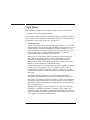
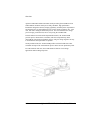
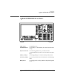
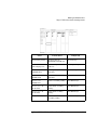
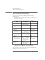
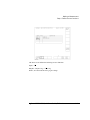
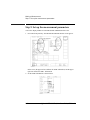
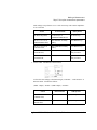
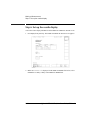
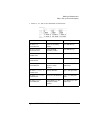
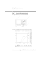
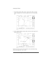
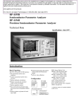
Quick Start Guide
Agilent 4155B Semiconductor Parameter Analyzer
Agilent 4156B Precision Semiconductor Parameter Analyzer
Agilent Part No. 04156-90300
Printed in Japan
January 2000
Edition 2
Legal Notice
The information contained in this document is subject to change without notice.
Copyright © 1997, 2000 Agilent Technologies
This document contains information which is protected by copyright. All rights are
reserved. Reproduction, adaptation, or translation without prior written permission
is prohibited, except as allowed under the copyright laws.
•
Product Warranty
Agilent Technologies warrant Agilent Technologies hardware, accessories and
supplies against defects in materials and workmanship for the period of one year
from the warranty start date specified below. If Agilent Technologies receive
notice of such defects during the warranty period, Agilent Technologies will, at
its option, either repair or replace products which prove to be defective.
Replacement products may be either new or like-new.
Warranty service of this product will be performed at Agilent Technologies.
Buyer shall prepay shipping charges to Agilent Technologies and Agilent
Technologies shall pay shipping charges to return the product to Buyer.
However, Buyer shall pay all shipping charges, duties, and taxes for products
returned to Agilent Technologies from another country.
Agilent Technologies do not warrant that the operation of Agilent Technologies
products will be uninterrupted or error free. If Agilent is unable, within a
reasonable time, to repair or replace any product to a condition as warranted,
customer will be entitled to a refund of the purchase price upon prompt return of
the product.
The Agilent Technologies products may contain remanufactured parts
equivalent to new in performance or may have been subject to incidental use.
The warranty period begins on the date of delivery or on the date of installation
if installed by Agilent Technologies. If customer schedules or delays Agilent
Technologies installation more than 30 days after delivery, warranty begins on
the 31st day from delivery.
Warranty does not apply to defects resulting from (a) improper or inadequate
maintenance or calibration, (b) software, interfacing, parts or supplies not
supplied by Agilent Technologies, (c) unauthorized modification or misuse, (d)
operation outside of the published environmental specifications for the product,
or (e) improper site preparation or maintenance.
2
Agilent 4155B/4156B Quick Start Guide, Edition 2
To the extent allowed by local law, the above warranties are exclusive and no
other warranty or condition, whether written or oral, is expressed or implied and
Agilent Technologies specifically disclaim any implied warranties or conditions
of merchantability, satisfactory quality, and fitness for a particular purpose.
Agilent Technologies will be liable for damage to tangible property per incident
up to the greater of $300,000 or the actual amount paid for the product that is the
subject of the claim, and for damages for bodily injury or death, to the extent
that all such damages are determined by a court of competent jurisdiction to
have been directly caused by a defective Agilent Technologies product.
To the extent allowed by local law, the remedies in this warranty statement are
customer’s sole and exclusive remedies. Expect as indicated above, in no event
will Agilent Technologies or its suppliers be liable for loss of date or for direct,
special, incidental, consequential (including lost profit or date), or other damage,
whether based in contract, tort, or otherwise.
For consumer transactions in Australia and New Zealand: the warranty terms
contained in this statement, except to the extent lawfully permitted, do not
exclude, restrict or modify and are in addition to the mandatory statutory rights
applicable to the sale of this product to you.
•
Assistance
Product maintenance agreements and other customer assistance agreements are
available for Agilent Technologies products.
For any assistance, contact your nearest Agilent Technologies Sales Office.
•
Certification
Agilent Technologies Inc. certifies that this product met its published
specifications at the time of shipment from the factory. Agilent further certifies
that its calibration measurements are traceable to the National Institute of
Standards and Technology (NIST), to the extent allowed by the Institute’s
calibration facility, and to the calibration facilities of other International
Standards Organization members.
Agilent 4155B/4156B Quick Start Guide, Edition 2
3
Printing History
Edition 1:
August 1997
Edition 2:
January 2000
4
Agilent 4155B/4156B Quick Start Guide, Edition 2
In This Guide Book
This guide book is a quick start guide for Agilent 4155B and Agilent 4156B. It
introduces basic measurement and analysis without a lot of explanation and details.
This guide consists of the following three chapters:
•
Overview: briefly introduces the 4155B/4156B, also provides solutions to
problems you may encounter while using this guide
•
Making a measurement: preparing for measurements and measuring a sample
device (MOS FET).
•
Analyzing a result: analyzing the results graphically and searching for the
threshold voltage (Vth) of the MOS FET.
You will find brief instructions for starting measurements with an 4155B/4156B.
Before going to the next page, make sure you have prepared the following:
•
Agilent 4155B or Agilent 4156B
•
Agilent 16442A test fixture
•
Test device (n-channel MOS FET, enhancement type) In this guide, the test
device used is a Siliconix SD214DE.
This guide book assumes that you have already installed your 4155B/4156B. If not,
refer to "Installation" in User's Guide General Information.
Text Conventions
The following text conventions are used in this guide:
Front-panel key
A key that is physically located on the 4155B/4156B.
Screen Text
Text displayed on the 4155B/4156B.
Italic
Refers to a related document, or is used for emphasis.
Agilent 4155B/4156B Quick Start Guide, Edition 2
5
Finding Further Information
This guide book is written for the 4155B/4156B beginners. See the following books
for further information:
•
User's Guide General Information provides general information of the
4155B/4156B.
•
User's Guide Measurement and Analysis provides information on how to use the
4155B/4156B for performing measurements and analysis.
•
Programmer's Guide provides information on how to control the 4155B/4156B
with remote commands.
•
GPIB Command Reference provides reference of GPIB commands.
•
SCPI Command Reference provides reference of Standard Commands for
Programmable Instruments (SCPI) commands.
•
Sample Application Programs' Guide Book provides description on some
sample application programs and setup files.
•
VXIplug&play Driver User's Guide provides description on the 4155B/4156B
VXIplug&play driver and the furnished application program and reference of
the 4155B/4156B and Agilent E5250A VXIplug&play driver's functions.
6
Agilent 4155B/4156B Quick Start Guide, Edition 2
1
Overview
Agilent 4155B/4156B Quick Start Guide, Edition 2
Overview
Agilent 4155B Semiconductor Parameter Analyzer and Agilent 4156B Precision
Semiconductor Parameter Analyzer are fully, automatic, high performance
instruments designed to measure, display graphically, and analyze the dc parameters
and characteristics of semiconductor devices such as diodes, transistors, ICs, solar
cells, and wafers during the fabrication process. You can evaluate device design,
process design, production line, and so on by using the 4155B/4156B.
In semiconductor research and development laboratories, the 4155B/4156B
provides precise characteristics evaluation, which is an important step in the
development of new high performance devices, and gives design engineers an easy
to use method of device parameter acquisition.
On the production line, the 4155B/4156B provides real-time feedback on wafer
evaluation to improve the semiconductor process and to increase production yields.
For semiconductor end users, the 4155B/4156B is ideal for circuit design
applications and incoming inspection.
1-2
Agilent 4155B/4156B Quick Start Guide, Edition 2
Overview
Agilent 4155B/4156B At a Glance
Agilent 4155B/4156B At a Glance
LINE switch
For applying power.
Flexible disk drive
For inserting a 3.5-inch diskette, which can be used for mass
storage.
Keyboard interface
For connecting keyboard. So, you can control the
4155B/4156B from keyboard as well as from the front-panel
keys.
Primary softkeys
For changing display screen and secondary softkey menu.
Secondary softkeys
For selecting variable names and alternatives, and changing
items.
Rotary knob
For changing values, moving a marker, and performing knob
sweep.
Agilent 4155B/4156B Quick Start Guide, Edition 2
1-3
Overview
Agilent 4155B/4156B At a Glance
Agilent 4155B
Agilent 4156B
SMU terminals
Terminals through which voltage and current are forced and
measured by SMUs.
Intlk interface
Terminal through which signals for interlock function pass. The
interlock function is for preventing electric shock.
1-4
Agilent 4155B/4156B Quick Start Guide, Edition 2
Overview
If You Have a Problem
If You Have a Problem
This section describes how to solve the following unexpected problems:
•
If the 4155B/4156B cannot be powered on
•
If display screen does not appear after applying power
•
If the 16442A test fixture is not stable
If the 4155B/4156B cannot be powered on
•
Check that the power cable is firmly connected to the 4155B/4156B and to
power outlet.
•
Check that the front-panel LINE switch is on.
•
Check that the voltage selector switch is set properly.
The voltage selector switch is located in the lower-right corner of the rear panel.
The following table shows the line voltage selector setting.
Line Voltage
84 to 124 Vac
200 to 248 Vac
•
Position
left
right
Check that the fuse is good.
The fuse holders located in the lower-right corner of the rear panel.
1. Turn the 4155B/4156B off and disconnect the power cable from the power
outlet.
2. Unscrew the fuse holder on the rear panel.
3. Inspect that the correct fuse is installed, and wire inside the fuse is not
broken by using a rester.
Line
Fuse Type
110/120 Vac
220/240 Vac
Time-delay type 8A, 250 Vac
Time-delay type 4A, 250 Vac
Agilent Part Number
2110-0383
2110-0014
4. Replace the fuse, if necessary. Then, screw in the fuse holder.
5. Turn the 4155B/4156B on.
Agilent 4155B/4156B Quick Start Guide, Edition 2
1-5
Overview
If You Have a Problem
If display screen does not appear after applying power
•
If Agilent 41501 SMU/Pulse Generator Expander is installed, first turn on the
41501, then turn on the 4155B/4156B.
•
If the self-test fails, see "If You Have a Problem" in the 4155B/4156B User's
Guide General Information.
If the 16442A test fixture is not stable
•
Install stabilizers on the 16442A.
For this procedure, see "Installation" in the 4155B/4156B User's Guide General
Information.
•
If you use the 16442A test fixture with Agilent 16440A selector or Agilent
16441A R-BOX, attach the 16442A to the 16440A or the 16441A by using
plates and screws.
For this procedure, see "Installation" in the 4155B/4156B User's Guide General
Information.
1-6
Agilent 4155B/4156B Quick Start Guide, Edition 2
2
Making a Measurement
Agilent 4155B/4156B Quick Start Guide, Edition 2
Making a Measurement
In this chapter, you learn how to execute the measurements with an 4155B/4156B
and to display the measurement results graphically. Id-Vg measurement of a MOS
FET is provided as an example. You learn step-by-step how to perform this
measurement.
2-2
Agilent 4155B/4156B Quick Start Guide, Edition 2
Making a Measurement
You measure the device under test (DUT) by using the measurement circuit as
shown in the following diagram. SMU2 and SMU3 sweep the same voltage to the
gate and drain. SMU3 measures the drain current (Id). The source and substrate are
connected to circuit common.
You should get result similar to the following figure. Gate voltage Vg (swept from
0 V to 2 V) is assigned to X axis, ÖId is assigned to Y1 axis, and ¶ÖId / ¶Vg is
assigned to Y2 axis.
Agilent 4155B/4156B Quick Start Guide, Edition 2
2-3
Making a Measurement
Step 1. Prepare for the measurement
Step 1. Prepare for the measurement
Before executing measurement, configure the 4155B/4156B and accessories.
1. Make sure that the 4155B/4156B is off.
2. Connect the 16442A test fixture to the 4155B/4156B. See next figure.
3. If you use the keyboard, connect it to the 4155B/4156B.
4. If you use the 4156B, connect as shown below:
16442A
Kelvin Triaxial Cables
Coaxial Cables
Interlock/LED Cable
4156B
4156B
cable
16442A
4156B
cable
16442A
Intlk
Interlock/LED a
Intlk
VSU 1
Coaxial b
VSU 1
SMU 1
Kelvin triaxial c
SMU 1
VSU 2
Coaxial b
VSU 2
SMU 2
Kelvin triaxial c
SMU 2
VMU 1
Coaxial b
VMU 1
SMU 3
Kelvin triaxial c
SMU 3
VMU 2
Coaxial b
VMU 2
a. Interlock/LED cable: Agilent 16493J
b. Coaxial cable: Agilent 16493B. You do not need to connect VSUs and
VMUs for this measurement.
c. Kelvin triaxial cable: Agilent 16493K
2-4
Agilent 4155B/4156B Quick Start Guide, Edition 2
Making a Measurement
Step 1. Prepare for the measurement
If you use the 4155B, connect as shown below:
16442A
Triaxial Cables
Coaxial Cables
Interlock/LED Cable
4155B
4155B
cable
16442A
Intlk
Interlock/LED a
Intlk
SMU 1
Triaxial b
SMU 2
Triaxial b
SMU 3
Triaxial b
SMU 4
Triaxial b
SMU 1
(blue label)
SMU 2
(blue label)
SMU 3
(blue label)
SMU 4
(blue label)
4155B
cable
16442A
VSU 1
Coaxial c
VSU 1
VSU 2
Coaxial c
VSU 2
VMU 1
Coaxial c
VMU 1
VMU 2
Coaxial c
VMU 2
a. Interlock/LED cable: Agilent 16493J
b. Triaxial cable: Agilent 16493C. You do not need to connect SMU4 for
this measurement.
c. Coaxial cable: Agilent 16493B. You do not need to connect VSUs and
VMUs for this measurement.
Agilent 4155B/4156B Quick Start Guide, Edition 2
2-5
Making a Measurement
Step 2. Mount your DUT on the test fixture
Step 2. Mount your DUT on the test fixture
1. Select a suitable socket module for your DUT.
2. Mount the socket module on the test fixture.
3. Mount your DUT on the socket module.
4. Make connections with four connection cables (miniature banana to pin plug).
You make the following connections:
•
Source to SMU1
•
Gate to SMU2
•
Drain to SMU3
•
Substrate to SMU1
Both the source and substrate terminals are connected to SMU1.
5. After finishing connections, shut the lid of the test fixture.
2-6
Agilent 4155B/4156B Quick Start Guide, Edition 2
Making a Measurement
Step 2. Mount your DUT on the test fixture
Wiring for the 4156B
For this measurement, non-Kelvin connections are used. So, connect only the force
terminals as shown in the following figure:
Wiring for the 4155B
Agilent 4155B/4156B Quick Start Guide, Edition 2
2-7
Making a Measurement
Step 3. Define the channel assignments
Step 3. Define the channel assignments
You set the connection information on the CHANNELS: CHANNEL DEFINITION
screen.
1. Turn on the 4155B/4156B. Self-test starts.
2. After self-test is finished, make sure that CHANNELS: CHANNEL
DEFINITION screen appears on the screen of the 4155B/4156B. If not, press
Chan front-panel key.
where, softkeys located bottom of screen are the primary softkeys, and softkeys
located right side of screen are the secondary softkeys.
3. Make sure that SWEEP is displayed in the MEASUREMENT MODE field. If
not, select SWEEP secondary softkey in the MEASUREMENT MODE field.
4. Set the connection information in the CHANNELS area as shown in the
following table:
2-8
Agilent 4155B/4156B Quick Start Guide, Edition 2
Making a Measurement
Step 3. Define the channel assignments
Action
on Front Panel
on Keyboard
To move the pointer,
use arrow keys of
MARKER/CURSOR area.
use arrow keys
To move the cursor to
edit in display area,
use arrow keys of
Edit area.
use Backspace key.
To enter "VS" in
VNAME field,
press . (period) and + keys,
then Enter.
type VS, then press Enter.
To enter "IS" in
INAME field,
press * and + keys,
then Enter.
type IS, then press Enter.
To set "V" in
MODE field,
select V secondary softkey.
press Shift-F1 keys.
To set "VAR1" in
FCTN field,
select VAR1' secondary
softkey.
press Shift-F4 keys.
To set "VAR1" in
FCTN field,
select VAR1 secondary
softkey.
press Shift-F2 keys.
To disable a unit,
select DISABLE UNIT
secondary softkey.
press Shift-F7 keys.
Agilent 4155B/4156B Quick Start Guide, Edition 2
2-9
Making a Measurement
Step 4. Define the user functions
Step 4. Define the user functions
You define the user functions on the CHANNELS: USER FUNCTION
DEFINITION screen.
1. Select USER FCTN primary softkey. The CHANNELS: USER FUNCTION
DEFINITION screen appears.
2. Enter the user function information as shown in the following table:
Action
on Front Panel
on Keyboard
To move the pointer,
use arrow keys of
MARKER/CURSOR area.
use arrow keys.
To move the cursor to edit
in display area,
use arrow keys of Edit
area.
use Backspace key.
To enter "SQID" in
NAME field,
press +, 2, *, / keys, then
Enter.
type SQID,
then press Enter.
To enter "SQRT(ID)" a
in DEFINITION field,
press +, 2, 3, p, blue key, (
keys, and ID secondary
softkey, then ) and Enter.
type SQRT(ID),
then press Enter.
To enter "DSQID" in
NAME field,
press /, +, 2, *, / keys, then
Enter.
type DSQID,
then press Enter.
To enter
"DIFF(SQID,VG)" b
in DEFINITION field,
press /, *, 7, 7, blue key, (,
blue key, +, 2, *, /, blue key,
type
DIFF(SQID,VG),
then press Enter.
To disable a user
function,
, (comma) keys, and
VG secondary softkey,
then ) and Enter.
select
DISABLE FUNCTION
secondary softkey.
press Shift-F7 key.
a. Square root operator (Ö ) is defined by "SQRT" built-in function.
b. Partial difference (¶/¶) is defined by "DIFF" built-in function.
After you complete the above instruction, the CHANNELS: USER FUNCTION
DEFINITION screen shows the following setup:
2-10
Agilent 4155B/4156B Quick Start Guide, Edition 2
Making a Measurement
Step 4. Define the user functions
The above screen defines the following two user functions:
SQID = ÖId
DSQID = ¶SQID / ¶Vg = ¶ÖId / ¶Vg
Where, Id is drain current and Vg is gate voltage.
Agilent 4155B/4156B Quick Start Guide, Edition 2
2-11
Making a Measurement
Step 5. Set up the measurement parameters
Step 5. Set up the measurement parameters
You set the output parameters on the MEASURE: SWEEP SETUP screen.
1. Press Meas front-panel key. The MEASURE: SWEEP SETUP screen appears.
In the screen, the upper left area defines the VAR1 information, and the upper
right area defines the VAR1’ information.
2. Set the VAR1 information as shown below:
2-12
Agilent 4155B/4156B Quick Start Guide, Edition 2
Making a Measurement
Step 5. Set up the measurement parameters
Drain voltage sweeps from 0 V to 2 V with 10 mV step. The current compliance
is set to 100 mA.
Action
on Front Panel
on Keyboard
To move the pointer,
use arrow keys of
MARKER/CURSOR area.
use arrow keys.
To set "SINGLE" in
SWEEP MODE field,
select SINGLE secondary
softkey.
press Shift-F1 keys.
To set "LINEAR" in
LIN/LOG field,
select LINEAR secondary
softkey.
press Shift-F1 keys.
To enter "2.000 V"
in STOP field,
press 2, then Enter.
type 2,
then press Enter.
To enter "10.00 mV"
in STEP field,
press 1, 0, m, then Enter.
type 10m,
then press Enter.
3. Set the VAR1’ information as shown below:
To force the same voltage to the drain and gate, set RATIO = 1 and OFFSET = 0.
Because VAR1’ is defined as follows:
(VAR1’ output) = RATIO ´ (VAR1 output) + OFFSET
Action
on Front Panel
on Keyboard
To enter "0.000 V" in
OFFSET field,
press 0, then Enter.
type 0, then press Enter.
To enter "1.000" in
RATIO field,
press 1, then Enter.
type 1, then press Enter.
Agilent 4155B/4156B Quick Start Guide, Edition 2
2-13
Making a Measurement
Step 6. Set up the results display
Step 6. Set up the results display
You set the results display information on the DISPLAY: DISPLAY SETUP screen.
1. Press Display front-panel key. The DISPLAY: DISPLAY SETUP screen appears.
2. Make sure GRAPHICS is displayed in the DISPLAY MODE field. If not, select
GRAPHIC secondary softkey in the DISPLAY MODE field.
2-14
Agilent 4155B/4156B Quick Start Guide, Edition 2
Making a Measurement
Step 6. Set up the results display
3. Set the X-, Y1-, and Y2-axes information as shown below:
Action
on Front Panel
on Keyboard
To enter "VG"
in NAME field,
select VG secondary
softkey.
press Shift-F3 keys.
To set "LINEAR"
in SCALE field,
select LINEAR
secondary softkey.
press Shift-F1 keys.
To enter "0.00000 V"
in MIN field,
press 0, then Enter.
type 0, then press Enter.
To enter "2.00000 V"
in MAX field,
press 2, then Enter.
type 2, then press Enter.
To enter "SQID"
in NAME field,
select MORE 1/2, then
SQID secondary
softkeys.
press Shift-F7 keys, then
Shift-F3 keys.
To enter "0.00000 A"
in MIN field,
press 0, then Enter.
type 0, then press Enter.
To enter "100.000mA"
in MAX field,
press 1, 0, 0, m, then Enter.
To enter "DSQID"
in NAME field,
select MORE 1/2, then
DSQID secondary
softkeys.
type 100m, then press
Enter.
Agilent 4155B/4156B Quick Start Guide, Edition 2
press Shift-F7 keys, then
Shift-F4 keys.
2-15
Making a Measurement
Step 7. Execute the measurement
Step 7. Execute the measurement
Press Single front-panel key to execute the measurement.
You will get measurement results as shown in the following example:
2-16
Agilent 4155B/4156B Quick Start Guide, Edition 2
3
Analyzing the Results
Agilent 4155B/4156B Quick Start Guide, Edition 2
Analyzing the Results
In the previous chapter, you measured the drain current (Id) while performing a
synchronous sweep of the gate voltage (Vg) and drain voltage (Vd). And the
measurement results were drawn graphically on the screen.
In this chapter, you analyze the measurement results on the graph and search
threshold voltage (Vth) of the DUT.
The basic algorithm to search for the threshold voltage is:
1. Assign gate voltage (Vg) to X-axis, ÖId to Y1-axis, and ¶ÖId / ¶Vg to Y2-axis.
2. Search for the maximum value of ¶ÖId / ¶Vg curve, which is also the point
where the gradient of ÖId curve is maximum.
3. Draw a tangent line to the point where the gradient of ÖId curve is maximum.
4. Read the X-coordinate value where the tangent line crosses the X-axis. This
value is threshold value (Vth).
3-2
Agilent 4155B/4156B Quick Start Guide, Edition 2
Analyzing the Results
1. Make sure that MARKER/CURSOR primary softkey is highlighted. If not,
select the MARKER/CURSOR primary softkey.
2. Select MARKER secondary softkey so that ON appears on the softkey. The
MARKER softkey is highlighted, and the markers appears on the measurement
curve.
Agilent 4155B/4156B Quick Start Guide, Edition 2
3-3
Analyzing the Results
3. Select AXIS primary softkey so that Y2 appears on the softkey. The Y2 axis is
highlighted.
4. Select MARKER MIN/MAX secondary softkey until the * marker moves to the
maximum point on the Y2 curve. The o marker (on Y1 curve) also moves to
same X-axis point, which is maximum gradient of Y1 curve.
3-4
Agilent 4155B/4156B Quick Start Guide, Edition 2
Analyzing the Results
5. Select AXIS primary softkey so that Y1 appears on the softkey. The Y1 axis is
highlighted.
6. Select LINE primary softkey. The secondary softkey menu changes.
Agilent 4155B/4156B Quick Start Guide, Edition 2
3-5
Analyzing the Results
7. Select LINE secondary softkey so that ON appears on the softkey. The LINE
softkey is highlighted, and a vertical line appears in the center of the plotting
area.
8. Select TANGENT MODE secondary softkey. The line becomes tangent to the o
marker of the Y1 curve.
Read the X-axis intercept value of the tangent line. This is the threshold voltage
(Vth). In the example above, Vth is 935 mV.
3-6
Agilent 4155B/4156B Quick Start Guide, Edition 2