1
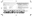
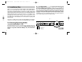
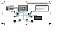
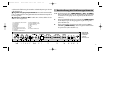
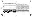
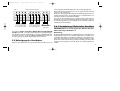
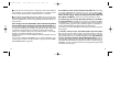
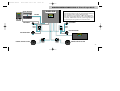
EA490200 Manual
28.07.2000 16:11 Uhr
Seite 1
5-CHANNEL POWER AMPLIFIER
INSTALLATION & OPERATING MANUAL / EINBAU- & BEDIENUNGSANLEITUNG
EA490200 Manual
2
28.07.2000 16:11 Uhr
Seite 2
EA490200 Manual
28.07.2000 16:11 Uhr
Seite 3
Contents/Inhalt
Design Features . . . . . . . . . . . . . . . . . . . . . . . . . . . . . . 5
Description of Connections & Controls . . . . . . . . . . . . 6
Installation Plan . . . . . . . . . . . . . . . . . . . . . . . . . . . . . 8
Amplification Modes . . . . . . . . . . . . . . . . . . . . . . . . . . 9
Wiring / Electrical Connection . . . . . . . . . . . . . . . . . . 10
System Configuration 2-Channel Input Mode . . . . . 12
System Configuration 4-Channel Input Mode . . . . . 13
Crossover Settings . . . . . . . . . . . . . . . . . . . . . . . . . . 14
Specifications . . . . . . . . . . . . . . . . . . . . . . . . . . . . . . 16
Warranty Policy . . . . . . . . . . . . . . . . . . . . . . . . . . . . 31
Technischer Aufbau / Merkmale . . . . . . . . . . . . . . . 18
Beschreibung der Bedienungselemente . . . . . . . . . . 19
Montageplan . . . . . . . . . . . . . . . . . . . . . . . . . . . . . . . 21
Betriebsarten & Lautsprecheranschlüsse . . . . . . . . . 22
Verkabelung / Elektrischer Anschluss . . . . . . . . . . . 23
Konfigurationsvorschlag 2-Channel Input Mode . . . 25
Konfigurationsvorschlag 4-Channel Input Mode . . . 26
Einstellungen . . . . . . . . . . . . . . . . . . . . . . . . . . . . . . . 27
Technische Daten . . . . . . . . . . . . . . . . . . . . . . . . . . . . 29
Garantiebestimmungen /Garantiekarte . . . . . . . . . 31
3
EA490200 Manual
28.07.2000 16:11 Uhr
Seite 4
EA490-200 Installation & Operation Manual
Congratulations
and thank you for choosing an EMPHASER 5-Channel Automotive Amplifier!
You now own a product of uncompromising engineering philosophy,
meticulous craftsmanship and unprecedented functionality, designed and
thoroughly tested by the laboratories of EMPHASER Inc., Wyoming USA.
To maximize the performance of your automotive audio system, we recommend that you acquaint yourself thoroughly with the capabilities and features
of the EA490-200 amplifier. Please read this manual carefully before undertaking the installation of the amplifier.
EMPHASER amplifiers are the result of outstanding craftsmanship and the
highest quality control standards. When properly installed these amplifiers
will provide you with many years of incomparable listening pleasure.
4
IMPORTANT NOTICE:
In case you are installing your EMPHASER amplifier yourself, you should have your installation checked and approved by an authorized, professional EMPHASER dealer/installer, in order to qualify for full warranty protection and to reach maximum power and audio performance
possible with your individual automotive audio system.
EA490200 Manual
28.07.2000 16:11 Uhr
Seite 5
EA490-200 Design Features
■ 5-Channel Amplifier, i.e. the all-in-one solution for a super
compact and user friendly realization of a fully active 5-channel high-end car audio system.
■ Dash-Mount Remote Subwoofer Level Control. The EA 490200 comes complete with a compact remote "SUB LEVEL" control which can
be mounted on or under the dashboard of your car. The "SUB LEVEL" control
allows the individual adjustment of the subwoofer volume.
The EA 490-200 will always store the last "Sub Level" adjustment in an EPROM
chip. Therefore it is also possible to make one specific "Sub Level" setting
after the installation of the system and then disconnect the control panel from
the amplifier.
■ Two Independent MOSFET Power Supplies for Satellite and
Subwoofer Amplification prevent any unwanted interference between
the two amplifier sections. This effectively eliminates audible cross-talk from
the power consuming bass amplifier onto the satellite channels.
■ Unique Hybrid Amplifier Switching Concept. The EA 490-200
incorporates two separate amplifier switching technologies: the satellite channels are using MOSFET (metal oxide semiconductor transistor) amplification, which is known for its outstanding performance in high-frequency reproduction. The amplification of the subwoofer channel is effected via a
BJT (bipolar junction transistor) amplifier, a switching technology renowned
for exceptional control and extended power handling.
■ 2 Ohm Stable Subwoofer Channel combined with an excellent
damping factor guarantees well-controlled and contoured bass reproduction.
■ Fully Active Integrated Electronic Frequency Filtering for all
amplifier sections. Both satellite sections (front and rear) feature individually adjustable high-pass filtering (HPF) between 50 and 250 Hz with a slope of 12 dB/oct. The independent low-pass (LPF) subwoofer channel is continuously adjustable from 40 to 120 Hz and features an exceptionally steep
slope of 24 dB/oct.
■ Uncompromising Design and Construction using only the best
electrical components including glass-fibre reinforced double-sided epoxy
circuit boards featuring the latest SMD (surface mounted device) PCB technology and high current handling 24 K gold-plated solid brass power and
signal connecting blocks/sockets and terminals.
■ Advanced Protection Circuitry 'sensing' short-circuits at the speaker outputs, DC voltage at the outputs and overheating of power electronics.
Faulty connections or operating modes will cause the amplifier to shut-off immediately.
■ Operating Mode/ Status / Protection - LED signaling operation and/or problems e.g. short-circuits, electrical or thermal overload of the
amplifier and DC voltage at the outputs.
5
EA490200 Manual
28.07.2000 16:11 Uhr
Seite 6
■ Adjustable Input Sensitivity accepting input voltages from 200
mV to 4 V allowing system combinations with almost every head-unit on the
market.
■ Soft Start / Soft Turn-Off for safe and silent switch-on/switch-off of
the amplifier.
■ External Fuses accessible from the amplifier bottom plate.
1. Front Input, LEFT Channel
2. Front Input, RIGHT Channel
3. LEVEL Sensitivity Front
4. FREQ. Hz Front Channels
5. LEVEL Sensitivity Rear
6. FREQ. Hz Rear Channels
7. INPUT MODE 2-CH/4-CH
8. Rear Input, LEFT Channel
9. Rear Input, RIGHT Channel
10. SUB FREQ. Subwoofer Channel
11. SUB LEVEL CONTROL INPUT
12. REAR SPEAKERS, - L +, - R +
13. FRONT SPEAKERS; - L +, - R +
14. SUBWOOFER (+/-)
15. GND
16. + 12V
17. REM
18. POWER/PROTECTION LED
1. Description of Connections & Controls
1 +2. RCA „FRONT INPUTS”/ „2-CHANNEL INPUT”
(„LEFT” & „RIGHT”) Low-level signal input for connection with
the head-unit. This input section is also used in combination with
the „INPUT MODE” switch in „2-CH” mode, i.e. when only
two channels are fed to the amplifier (instead of 4). Please also
consult section 2.2 und 2.6.1.
3.
4.
Input Sensitivity Control for the front speakers/satellite system
(„FRONT LEVEL”) allowing to match the RCA line output of the
head-unit to the amplifier input section. Please consult section 3.2.
Highpass Frequency Control for the front speakers /front satellite
system („FRONT FREQ.”), see section 3.1.
EMPHASER EA490-200
5-Channel Amplifier
Side View Input/Output
Control Panel
6
EA490200 Manual
28.07.2000 16:11 Uhr
Seite 7
5.
Input Sensitivity Control for the rear speakers/satellite system („REAR
LEVEL”) allowing to match of the RCA line output voltage of the headunit to the amplifier input section. Please consult section 3.2.
12.
Speaker Connecting Terminal for the ,,REAR SPEAKERS”
(„R” and „L”) allowing the connection of one pair of 2 ohms rear
satellites, see section 2.6.2.
6.
Highpass Frequency Control for the rear speakers /rear satellite system
(„REAR FREQ.”), see section 3.1.
13.
7.
„INPUT MODE” DIP-Switch with two positions: „4-CH” input setting if 4 pre-out channels (front and rear, each stereo) are fed to the
EA 490-200. „2-CH” input setting in case the complete 5-channel
system is only driven by 2 pre-out channels from the head-unit, see
section 2.2.
Speaker Connecting Terminal for the „FRONT SPEAKERS”
(„R” and „L”) allowing the connection of one pair of 2 ohms front
satellites see section 2.6.2.
14.
Speaker Connecting Terminal for the „SUBWOOFER” („+/-”)
allowing the connection of a subwoofer with any load between
2 and 4 ohms, see section 2.6.3.
15.
„GND” for connection to chassis ground or negative terminal of
car battery, see section 2.6.5.
16.
„+12 V” for connection to positive terminal of car battery, see
section 2.6.4.
17.
„REM” (Switching Contact) for the automatic (remote) turn-on / turnoff of the power amplifier from the head-unit's remote lead
(or antenna control lead), see section 2.6.2.
18.
Status-LED „POWER / PROTECTION” signalling operating mode
or faults, see section 2.6.6.
19.
„FUSES” located under the bottom for protection of the amplifierinternal electronics against overload or wrong operation /
manipulation.
8 + 9. RCA „REAR INPUTS” („4-CHANNEL INPUT” Mode),
„LEFT” & „RIGHT” Low-level signal input for connection with headunit. This input section is used in combination with the „INPUT MODE”
switch in „4-CH” mode, i.e. when all 4 channels are fed to the
amplifier. Please also consult section 2.2 und 2.6.1.
10.
Lowpass Frequency Control for the subwoofer („SUB FREQ.”), see
section 3.1.
11.
AT&T / RJ-11 socket for the „SUB LEVEL CONTROL INPUT”,
allowing connection of the remote dash-mount „Sub Level Control”
unit, see section 2.6.1.
7
EA490200 Manual
28.07.2000 16:11 Uhr
Seite 8
2.1 Installation Plan
Before you proceed any further with the installation of the EA 490-200 amplifier, it is recommended to map out the complete audio system and the required wiring. Consider all electrical requirements, as well as safe mounting
of the amp unit, sufficient ventilation, convenient accessibility of all fuses and
gain/frequency knobs. Please note that - because of possible interference
problems with the existing car wiring and electronics - especially the routing
of the RCA signal cables and the chassis ground connection will have a profound influence on a trouble-free operation of the overall system. For optimum performance of this amplifier, it is recommended to use quality installation material.
■ ,,2-CH INPUT MODE” is used with head units featuring only
one pair of RCA stereo pre-outs usually the rear pre-outputs (L&R). In
this case, the amplifier will be switched into „2-CH” mode (DIP switch up, see
fig. 1). This mode will let the amplifier distribute the incoming signal evenly
between front and rear channels, plus the subwoofer channel. In „2-CH” input
mode the front/rear fader option of the head-unit is de-activated; i.e. the relative levels between the front and rear satellite speaker
system have to be set on the amplifier. The subwoofer channel always remains unaffected by the front/rear satellite setting..
fig. 1
If you have no or little experience with car audio installations, we strongly recommend to consult your nearest authorized EMPHASER dealer/installer.
FRONT INPUTS
LEFT
RIGHT
(2-CH INPUT)
2.2 Selecting Operating Modes
FRONT
LEVEL
FREQ.
125
50Hz 250Hz
(„2-CH/4-CH INPUT MODE” switch)
The EA 490-200 offers two basic operating modes, depending on the number of input channels used from the head-unit. Note: If your head-unit
features a separate subwoofer RCA pre-out, it should not be
used!
8
REAR INPUTS
LEFT
RIGHT
REAR
LEVEL
FREQ. INPUT MODE
125
2-CH
50Hz 250Hz 4-CH
SUB LEVEL CONTROL
INPUT
SUB FREQ.
FREQ. INPUT MODE
REAR SPEAKERS
R
L
125
FRONT SPEAKERS
R
2-CHL
SUBWOOFER
GND
+12V
80
40Hz 120Hz
Hz 250Hz 4-CH
L
R
RCA Inputs
from
head-unit
Dip Switches
Up for „2-CH”
INPUT MODE
EA490200 Manual
28.07.2000 16:11 Uhr
Seite 9
■ „4-CH INPUT MODE” is used with head units featuring two
pairs of RCA stereo pre-outs i.e. front and rear pre-outputs (each L&R).
In this case, the amplifier must be switched to „4-CH” input mode (DIP
switch down, see fig. 2. As the „4-CH” input mode operates with 2 pairs of
RCA inputs, it also provides full support of the fader control of the headunit. The subwoofer channel always remains unaffected by the front/rear
satellite fader setting.
Please note: The EA 490-200 is a 5-channel concept amplifier featuring
high-pass filtering (HPF) for all satellite channels and low-pass filtering (LPF)
for the subwoofer channel. Therefore these HPF and LPF filters may be individually adjusted in their respective cut-in/cut-off frequency range, but they
cannot be switched off or by-passed completely.
fig. 2
LEF
FRONT INPUTS
LEFT
RIGHT
(2-CH INPUT)
FRONT
LEVEL
FREQ.
125
REAR INPUTS
LEFT
RIGHT
REAR
LEVEL
50Hz 250Hz
FREQ. INPUT MODE
125
SUB LEVEL CONTROL
INPUT
SUB FREQ.
2-CH
80
50Hz 250Hz 4-CH
REAR SPEAKERS
R
FREQ. INPUT MODE
FRONT SPEAKERS
L
125
R
L
2-CH
GND
+12V
40Hz 120Hz
L
R
L
R
Rear
RCA
Inputs
The location of the amplifier should be carefully selected. In the interest of passive driver and passenger safety, the amplifier must be securely mounted.
Check the suitability of your preferred amplifier location carefully before the
installation. The mounting location should be either in the trunk or in the passenger compartment. The actual mounting surface should be completely
flat. Any mounting position allowing for a good air stream across the cooling
fins of the amplifier's heatsink will improve cooling (operating temperature!) and long-term stability dramatically. Make sure there is no wiring harness, fuel tank etc. behind or below the mounting surface, that may be damaged by the drilling of the holes for the amplifier mounting screws. After installation there should be a clearance of at least 5cm on all sides including
the ventilated top of the amplifier heatsink. Make sure the unit is not exposed to direct sunlight, humidity, water, oil or other fluids that may enter the
amplifier.
SUBWOOFER
0 Hz 250 Hz 4-CH
Front
RCA
Inputs
2.3 Location of the Amplifier
Dip Switches
Down for „4-CH”
INPUT MODE
2.4 Amplification Modes
The EA490-200 is a full concept amplifier, i.e. an all-in-one solution for a super compact and user friendly realization of a fully active high-end car audio amplification. The EA 490-200 allows the cross-over controlled amplification of a complete satellite/subwoofer audio concept, i.e. 2 pairs of satel9
EA490200 Manual
28.07.2000 16:11 Uhr
fig. 3
R
Seite 10
Speaker Connections
L
R
L
2.5 Mounting the Amplifier
GND
Once the location for the amplifier is defined, use the unit as a template for
the marking of the mounting holes with a pencil or felt-tip. The mounting holes should be pilot-drilled using a 2,5mm or 3mm drill. For the actual mounting the supplied rubber washers have to be pressed into the mounting holes from the top before inserting the supplied mounting screws. The rubber
washers protect the amplifier from electrical ground-loops that can easily result in audible hum!
2.6.1 Wiring / Electrical Connection
Front Satellites L&R
min. 2 Ohms impedance
Rear Satellites L&R
min. 2 Ohms impedance
Subwoofer
2–4 Ohms impedance
lites front and rear component or coaxial systems) with an impedance of at
least 2 ohms and one subwoofer channel for the bass reproduction at a minimum load impedance of 2 ohms. The front- and rear- speaker outputs of
the EA490-200 are not bridgeable. For speaker connecting reference
see fig.3 or the system configurations overleaf. Should you intend to use only
one pair of satellites (plus subwoofer) with this amplifier, they have to be
connected to the „Front Speakers” terminals with the amplifier switched to
„4-CH INPUT MODE”.
10
IMPORTANT NOTICE: Disconnect the positive battery terminal
(+12V) or remove the main fuse near the car battery before
any wiring work! Please note that the power supply of the
car must remain disconnected, until the entire wiring installation is completed.
Speaker Impedance Specifications
The heat dissipation capacity of this 5-channel amplifier has been designed
to operate with two pairs of satellites with a minimum impedance of 2 ohms
(per satellite) and a subwoofer channel with a minimum impedance of 2
ohms. These minimum impedances must not be decreased any further, as
EA490200 Manual
28.07.2000 16:11 Uhr
Seite 11
the resulting excess heat generation inside the amplifier will cause the thermal protection circuitry to shut-off the amplifier.
■ Use rubber grommets when running cables through any metal or sharp
plastic to prevent accidental shorting or shearing. Make sure the cables do
not interfere with normal operation of the vehicle.
■ Especially the music signal cables (RCA interconnects) should be kept far
away from any potential sources of electrical interference e.g. electronic
vehicle management systems (engine computers, relays etc.) fuel pumps, wiring harnesses etc.!
2.6.2 Carefully run the audio signal and remote switching cables and the remote bass control cable from the head-unit
or dashboard to the amplifier. The audio signal cables should be routed completely separate from the power cables. Use only double or triple shielded quality cables!
Connect the remote (turn on/turn off) lead to the respective output/input of
the head-unit and the amplifier. If your head-unit does not have a separate
remote lead you may also use the antenna remote output. Now you can
connect the audio cable to the respective outputs on the head-unit and the
inputs of the amplifier.
Mount the remote ”Sub Level CONTROL” unit in a convenient position on
or under the dashboard and connect the cable between the remote control
unit and the amplifier (”SUB LEVEL CONTROL INPUT”).
2.6.3 Connect the loudspeaker wires as shown in fig. 3. Use
good quality speaker wires of minimum 1,5mm2 - preferably 2,5mm2 crosssection. Start with loosen the allen screws of the respective screw terminals.
When stripping the wires for connection, remove approximately 8mm of the
insulation and insert the bare ends into the corresponding speaker terminal
output on the amplifier. Be sure to follow correct polarity of each wire.
Tighten the allen screws of the amplifier.
2.6.4 Run the positive power cable („+12 V”) directly from
the positive terminal of the car battery to the amplifier. To protect your car audio system and your entire car against electrical fire hazards
from a short-circuit of the main power cable with chassis ground, you must
insert a main fuse (holder) within the first 30cm of the battery. The fuse type/value should be matching the limitations of your main power cable and the requirements of your car audio system, in case of the EA490-200, the minimum vakue is 60 Ampere! Do not insert the main fuse until the entire installation is completed!
2.6.5 Now you route the ground cable to the amplifier. Try to
find a GND contact very close to the amplifier. The ground power cable must
have the same cross-section as the positive power cable. It is recommended to use a corrosion-resistant gold-plated power ring between the ground
cable and the chassis ground point. The contact point on the car chassis
should therefore be solid and clean, i.e. free from rust or paint etc. A bad
11
EA490200 Manual
28.07.2000 16:11 Uhr
Seite 12
System Configuration 2-CHANNEL INPUT MODE
EA490-200
CD/MD CHANGER
SUB LEVEL
CONTROL
REMOTE
PANEL
CONTROL
SUB LEVEL
CONTROL
Please note!
all Satellites are driven in High-Pass Mode
Subwoofer channel is driven in Low-Pass Mode
all Satellites must be 2 Ohms or more
Subwoofer may be 2 - 4 Ohms
2-Channel Input Mode does not
support fader control on head-unit
●
●
●
●
●
1 PRE-OUT
HEAD-UNIT
TWEETER
TWEETER
G r e a t
A m e r i c a n
C a r
A u d i o
G r e a t
G r e a t
A m e r i c a n
C a r
A m e r i c a n
C a r
A u d i o
A u d i o
G r e a t
PASSIV
X-OVER
A m e r i c a n
C a r
A u d i o
PASSIV
X-OVER
BASS/MIDRANGE
BASS/MIDRANGE
G r e a t
G r e a t
A m e r i c a n
C a r
A u d i o
COAXIAL/TRIAXIAL SYSTEM
12
PASSIV
INLINE
X-OVER
A m e r i c a n
C a r
A u d i o
A u d i o
A u d i o
C a r
C a r
A m e r i c a n
A m e r i c a n
G r e a t
G r e a t
PASSIV
INLINE
X-OVER
TRUNKBOX SUBWOOFER
COAXIAL/TRIAXIAL SYSTEM
EA490200 Manual
28.07.2000 16:11 Uhr
Seite 13
System Configuration 4-CHANNEL INPUT MODE
EA490-200
CD/MD CHANGER
●
●
●
●
●
2 PRE-OUT
FRONT & REAR
SUB LEVEL
REMOTE
CONTROL
SUB LEVEL
CONTROL
Please note!
HEAD-UNIT
TWEETER
all Satellites are driven in High-Pass Mode
Subwoofer channel is driven in Low-Pass Mode
all Satellites must be 2 Ohms or more
Subwoofer may be 2 - 4 Ohms
4-Channel Input Mode supports fader
control on head-unit
TWEETER
G r e a t
A m e r i c a n
C a r
A u d i o
G r e a t
G r e a t
A m e r i c a n
C a r
A m e r i c a n
C a r
A u d i o
A u d i o
G r e a t
PASSIV
X-OVER
A m e r i c a n
C a r
A u d i o
PASSIV
X-OVER
BASS/MIDRANGE
BASS/MIDRANGE
G r e a t
G r e a t
A m e r i c a n
C a r
A u d i o
COAXIAL/TRIAXIAL SYSTEM
PASSIV
INLINE
X-OVER
A m e r i c a n
C a r
A u d i o
A u d i o
A u d i o
C a r
C a r
A m e r i c a n
A m e r i c a n
G r e a t
G r e a t
PASSIV
INLINE
X-OVER
TRUNKBOX SUBWOOFER
COAXIAL/TRIAXIAL SYSTEM
13
EA490200 Manual
28.07.2000 16:11 Uhr
Seite 14
2.6.6 Close the electrical circuit by inserting the main fuse.
After turning-on the head-unit, the „Power/Protection” LED of the amplifier
should light-up green. If the LED is red, the installation is faulty, turn the headunit off immediately and re-check steps 2.6.1 to 2.6.5. The same applies if
the amplifier LED does not light up at all.
will be the reproduction of the mid-bass frequencies and the power-handling
of the satellites (cone excursion of the mid/woofers!). If the satellite cross-over
frequency is too low, the mid-bass reproduction will be increased, but the power-handling will decrease at the same time. If the cross-over frequency is
set too high, the mid-bass reproduction will become 'thin', while the powerhandling of the satellite speakers will increase. Try to find the settings that will
suit your personal listening preferences and the physical and electrical capabilities of your equipment best.
3.1 Cross-Over Settings
As a general rule you can get good results around the following High-Pass
Recommendations:
ground contact reduces the voltage, resulting in reduced power output and
high distortion.
The EA490-200 is a concept amplifier, therefore the actual speaker outputs
will receive HPF or LPF filtered amplified signals, and the speakers will only
have to work in the frequency bands they will reproduce best. Before the respective sensitivity levels of the individual amplification systems can be set, it
is advisable to set the system appropriate cross-over frequencies for all speaker systems.
Satellite High-Pass Frequencies (Front & Rear „FREQ. Hz”)
It is recommended to set the high-pass cross-over frequency between 50 and
250 Hz using the „FREQ. Hz” controls. The appropriate setting should be determined by ear. The two most important factors for the individual adjustment
14
Front Satellite Speaker System („FRONT FREQ.”)
X-Over Freq.
10 cm/4” Coaxial or Separate Component System
13 cm/5” Coaxial or Separate Component System
16 cm/6” Coaxial or Separate Component System
90 Hz
80 Hz
70 Hz
Rear Satellite Speaker System („REAR FREQ.”)
X-Over Freq.
10 cm/4” Coaxial or Separate Component System
13 cm/5” Coaxial or Separate Component System
16 cm/6” Coaxial or Separate Component System
100 Hz
120 Hz
130 Hz
EA490200 Manual
28.07.2000 16:11 Uhr
Seite 15
Subwoofer Low-Pass Frequency („SUB FREQ.”)
Ideally, the low-pass (LPF) cut-off frequency for the subwoofer should be set
between 50 to 90 Hz. The actual setting should be 'played by ear', i.e. set the
„SUB FREQ.” control in such a way that the bass reproduction is stiff and rich,
while still delivering a good and solid low-end extension.
3.2 Input Sensitivity Settings („LEVEL”)
To reach a maximum noise-free dynamic headroom from each individual
head unit/amplifier/speaker combination, it is important to set the respective input sensitivity controls („LEVEL”) correctly. On the one hand the sensitivity settings determine the actual signal-to-noise ratio, on the other hand the
sensitivity setting also controls the maximum distortion-free SPL (sound pressure level) possible with a specific car audio system.
3.2.1 Tips for Appropriate Sensitivity Settings
Before you start, all tone controls (Bass, Mid, Treble) and all fader and balance controls on the head unit have to be set to neutral or center position. The
„Loudness” function must be deactivated.
Turn both satellite „LEVEL” controls (Front and Rear) on the amplifier counterclockwise to their minimum positions. Turn-on your head-unit and keep the
volume control to the minimum! Press the „DOWN” button of the sub remote
control unit until you have reached zero level.
Now you set the volume control of your head-unit to approximately 3/4 of
full volume, while playing a dynamic track from a CD. Slowly increase the
sub channel level control by pressing the „UP” button until you can just about hear distorted bass sounds. Now you reduce the main volume level on
the head-unit to a medium listening level.
Now you start turning up the FRONT satellite „LEVEL” control clockwise,
until you have reached a good tonal balance between the front satellites and
the sub channel, a slight forwardness of the bass range should be preferred,
as this will be compensated later by normal driving noises.
Now you turn up the REAR satellite „LEVEL” control clockwise until you feel
that you have reached an appropriate sound level in the back of the car, so
that the total sound reproduction becomes smooth and homogenous.
Finally you should fine-tune the LPF cross-over frequency on the amplifiers
„SUB FREQ.” control.
Obviously, it is also possible to make a fixed sub channel setting by first setting the desired subwoofer level on the remote „SUB LEVEL CONTROL”
and then unplugging the remote cable from the amplifier. The last sub level
setting will be automatically stored by the amplifier.
15
EA490200 Manual
28.07.2000 16:11 Uhr
4. Specifications
EA490-200 5-Channel Amplifier
Seite 16
Rated Power Output (RMS)
Front / Rear Channels and
Subwoofer Channel at 4 ohms (13.8 V)
(THD = <1 %)
Rated Power Output (RMS)
Front / Rear Channels at 2 ohms and
Subwoofer Channel at 2 ohms (13.8 V)
(THD < = 0,1 %)
4 x 125 W (Satellites) / 1 x 300 W (Subwoofer)
Damping Factor
Front / Rear Channels
Subwoofer Channel
at 4 Ohms
> 200
> 300
Signal-to-Noise Ratio (A-Filter)
> 100 dB
Frequency Response
(Front- / Rearplus Subwoofer Channel)
(+0 dB / - 1 dB)
Channel Separation
Input Sensitivity
Integrated Cross-Over/Filtering
Slope Rate
Cross-Over Frequency
16
4 x 90 W (Satellites) / 1 x 200 W (Subwoofer)
10 Hz - 40 kHz
> 55 dB
200 mV - 4 V
High-Pass/ Front & Rear Channels
12 dB / Octave
continuously adjustable 50 - 250 Hz
Fuse
2 x 30 A
Dimensions W x H x D
368 x 53 x 208 mm
Low-Pass Subwoofer Channel
24 dB / Octave
continuously adjustable 40 - 120 Hz
EA490200 Manual
28.07.2000 16:11 Uhr
Seite 17
EA490-200 Bedienungs- und Installationsanleitung
Herzlichen Glückwunsch!
Wir gratulieren Ihnen zum Kauf der EMPHASER EA 490-200 Fünfkanalendstufe, einem Top-Produkt von EMPHASER Inc., Wyoming / USA.
Ausgestattet mit einem kompromisslosen technischen Aufbau, setzt dieser
Fünfkanal Car-Amp Masstäbe bezüglich Leistungsabgabe, Klangqualität und
Bedienungsfreundlichkeit.
Damit Sie die Wiedergabequalität und die Leistungsfähigkeit dieses Verstärkers voll ausschöpfen können, bitten wir Sie, sich eingehend mit den Möglichkeiten und technischen Features dieses Verstärkers vertraut zu machen.
Lesen Sie deshalb die nachfolgenden Abschnitte sorgfältig durch und bewahren Sie diese Bedienungsanleitung für allfällige, vielleicht später auftauchende Fragen auf.
korrekte Installation vorausgesetzt, viele Jahre unvergleichlichen Hörspass
bereiten. Falls Sie weitere Fragen bezüglich der Anschlussmöglichkeiten
des Gerätes oder dessen Installation haben, lassen Sie sich von Ihrem
EMPHASER Händler beraten.
WICHTIG FÜR IHREN GARANTIE-SCHUTZ:
Wenn Sie den Einbau Ihres Auto-HiFi Systems selbst vornehmen, lassen Sie dieses von Ihrem EMPHASER-Händler
auf fachgerechte Installation überprüfen und auf der Garantiekarte bestätigen. Damit sichern Sie sich Ihre Garantieleistungen und stellen sicher, dass die Anlage ihre volle
Klangqualität und Leistungsfähigkeit erreicht.
EMPHASER Car-HiFi Verstärker sind Produkte, die in Handarbeit mit höchsten Qualitätsstandards und Kontrollen hergestellt werden. Sie werden Ihnen,
17
EA490200 Manual
28.07.2000 16:11 Uhr
Seite 18
Technischer Aufbau / Merkmale
nimmt ein für seine hervorragende Kontrolle und Leistungsfähigkeit berühmter BJT-Verstärker.
■ Fünfkanalverstärker zur Realisierung eines einbaufreundlichen und
klangstarken 5-Kanal Subwoofer/Satelliten Konzeptes, z.B. bestehend aus
zwei Paar Komponentenlautsprecher (Front- und Heckbereich) und einem
Subwoofer.
■ 2 Ohm-Stabilität der Satellitenkanäle und des Subwooferkanals.
Dies bewirkt im Zusammenspiel mit dem exzellenten Dämpfungsfaktor
enorme Leistungsreserven und absolute Kontrolle des angeschlossenen Subwoofers und der Satellitenlautsprechern.
■ Subwooferpegelregelung über externe Fernbedienung. Das
im Cockpit des Fahrzeuges frei montierbare kleine „Sub Level CONTROL„
Bedienteil ermöglicht die Fernbedienung der Lautstärke des Subwoofers. Dadurch kann der absolute Bass-pegel der Quelle (Cassette, MD oder CD), dem
Geschmack und der Aufnahme während der Fahrt angepasst werden. Der
zuletzt eingestellte Wert wird digital im EPROM-Chip gespeichert, sodaß z.B.
auch eine einmalige Einstellung vorgenommen werden kann und das Bedienteil am Verstärker anschliessend wieder abgezogen wird.
■ Integrierte elektronische Frequenzweichen mit einer Flankensteilheit von 12 dB/Okt. bei den hochpassgefilterten Front- und Rear- Kanälen
und einem 24 dB/Okt. Tiefpassfilter für den Subwooferkanal. Zusätzlich stufenlos regelbare Trennfrequenzen im Bereich zwischen 50 bis 250 Hz
bei den Satellitenkanälen und einem Bereich von 40 bis 120 Hz beim Subwooferkanal.
■ Zwei einzelne vollständig getrennte MOSFET - Netzteile für
Satelliten- und Subwoofer- Verstärkersektionen verhindern eine
gegenseitige Beeinflussung der einzelnen Verstärkungszüge. Dies verhindert
ein klanglich ungünstiges Übersprechen des leistungsintensiven Bassbereiches auf die Satellitenkanäle.
■ Spezielle Schaltungstechnik: Die Verstärkung der vier Satellitenkanäle erfolgt mit für ihre ausgezeichneten klanglichen Eigenschaften bekannten MOSFET-Verstärker, die Verstärkung des Subwooferkanals über18
■ Kompromissloser Aubau und Konstruktion durch den Einsatz
von neuesten Schaltungstechniken und ausschliessliche Verwendung von hochwertigsten Materialien in der Fertigung, wie z.B. SMD-bestückte doppelseitig kaschierte Glasfaserepoxydharzplatinen oder hochstromfähige, 24K hartvergoldete Strom- und Lautsprecheranschlussblöcke aus Massivmessing.
■ Intelligente Schutzschaltungwelche Kurzschlüsse an den Lautsprecherausgängen, Gleichspannung im Ausgangssignal und überhöhte Betriebstemperatur erkennt. Fehlerhafte Betriebszustände führen zum sofortigen Abschalten des Gerätes.
■ Betriebsanzeige / Protection - LED zeigt Kurzschlüsse, elektrische-
EA490200 Manual
28.07.2000 16:11 Uhr
Seite 19
und thermische Überlastung des Verstärkers und Gleichspannung an den Anschlussklemmen an.
1. Beschreibung der Bedienungselemente
■ Regelbare Eingangsempfindlichkeit mit einem breiten Einstellbereich von 200 mV bis 4 V. Ermöglicht dadurch die Kombination mit prakt. allen Steuergeräten.
1+2. Cinch Eingangsbuchsen „FRONT INPUTS” („LEFT” & “RIGHT”;
linker und rechter Kanal vorne). NF-Signal Eingang für den Anschluss
der Cinch Front-Ausgänge des Steuergerätes (siehe Abschnitt 2.2
und 2.6.1)
■ Soft Start / Soft Turn-Off für sanftes Ein- und Ausschalten des Verstärkers ohne Störgeräusche.
1 + 2. FRONT INPUTS: LEFT & RIGHT
3. FRONT LEVEL
4. FRONT FREQ.
5. REAR LEVEL
6. REAR FREQ.
7. INPUT MODE: 2-CH od. 4-CH
8 + 9. REAR INPUTS: LEFT & RIGHT
10. SUB FREQ.
11. SUB LEVEL CONTROL INPUT
12. REAR SPEAKERS: R und L
13. FRONT SPEAKERS: R und L
14. SUBWOOFER (+ /-)
15. GND
16. + 12 V
17. REM
18. POWER / PROTECTION
3.
Eingangsempfindlichkeitsregler der Front-Kanäle („FRONT LEVEL”)
für die Anpassung an die Ausgangsspannung des Steuergerätes
(siehe Abschnitt 3.2).
4.
Regler zum Einstellen der Hochpass-Trennfrequenz der FRONT
SPEAKERS („FRONT FREQ.”) an der integrierten elektronischen
Frequenzweiche (siehe Abschnitt 3.1).
EMPHASER
EA490-200
Fünfkanalendstufe
Anschlusseite
19
EA490200 Manual
28.07.2000 16:11 Uhr
Seite 20
Eingangsempfindlichkeitsregler der Rear-Kanäle („REAR LEVEL”)
für die Anpassung an die Ausgangsspannung des Steuergerätes
(siehe Abschnitt 3.2).
13.
6.
Regler zum Einstellen der Hochpass-Trennfrequenz der REAR
SPEAKERS („REAR FREQ.”) an der integrierten elektronischen
Frequenzweiche (siehe Abschnitt 3.1).
14. Lautsprecheranschlussterminal „SUBWOOFER” („+/-”) für den
Anschluss von einem Subwoofer mit 4 Ohm oder 2 Ohm Abschlussimpedanz (siehe Abschnitt 2.6.2).
7.
Eingangs-/Betriebswahl-Schalter „INPUT MODE” für die Ansteuerung des Verstärkers mittels eines oder zwei Paar („2-CH od.
4-CH”) Cincheingängen (siehe Abschnitt 2.2).
15. „GND” für den Anschluss an die Chassis-Masse des Kfz (siehe
Abschnitt 2.6.5).
8+9. Cinch Eingangsbuchsen „REAR INPUTS” („LEFT” & „RIGHT”;
linker und rechter Kanal hinten). NF-Signal Eingang für den
Anschluss der Cinch Rear-Ausgänge des Steuergerätes (siehe Abschnitt 2.2 und 2.6.1)
20
Lautsprecheranschlussterminal „FRONT SPEAKERS” („R” und „L”)
für den Anschluss von einem Paar 4 Ohm Front-Satellitenlautsprecher
(siehe Abschnitt 2.6.2).
5.
10.
Regler zum Einstellen der Tiefpass-Trennfrequenz („SUB FREQ.”)
an der integrierten elektronischen Frequenzweiche (siehe Abschnitt 3.1).
11.
Buchse „SUB LEVEL CONTROL INPUT” für den Anschluss des
Kabels vom externen „SUB LEVEL CONTROL”/Basspegel-Regler
(siehe Abschnitt 2.6.1)
12.
Lautsprecheranschlussterminal „REAR SPEAKERS” („R” und „L”)
für den Anschluss von einem Paar 4 Ohm Rear-Satellitenlautsprecher (siehe Abschnitt 2.6.2).
16. „+ 12 V” für den Anschluss an den Pluspol der Autobatterie (siehe
Abschnitt 2.6.4).
17. „REM” (Remote) Anschluss für die Ein- bzw. automatische Abschaltung des Verstärkers über den Amp- oder Antenna-Remote
Anschluss des Steuergerätes (siehe Abschnitt 2.6.2).
18. Betriebszustands-LED „POWER / PROTECTION” signalisiert
den Betriebszustand (siehe Abschnitt 2.6.6).
19. „FUSES” (Sicherungen) für die interne Absicherung des Verstärkers
gegen Überlastung und Fehlmanipulation. Verwenden Sie für dieses
Modell nur 30 Ampere Sicherungen zugänglich über die Bodenplatte
des Verstärkers.
EA490200 Manual
28.07.2000 16:11 Uhr
Seite 21
2.1 Montageplan
Bevor Sie mit der Montage beginnen, erstellen Sie am besten eine kurze Anschluss- und Installationsskizze. Zu berücksichtigen gilt es dabei hauptsächlich die Kabelverläufe und den Installationsort des Car-Amps.
Beachten Sie bitte, dass die Kabelführung sowie der Massepunkt einen entscheidenden Einfluss auf das störungsfreie Funktionieren Ihrer Anlage hat.
Besondere Aufmerksamkeit verdient auch die korrekte Plazierung des Verstärkers (ausreichende Luftzufuhr!), die richtige Stellung des Input Mode
Wahlschalters für die Ansteuerung des Verstärkers über ein Paar Cinchkabel (via Front Ausgang vom Radio), oder über zwei Paar Cinchkabel (Front
+ Rear Ausgang vom Radio), sowie die Qualität des verwendeten Zubehörs
zur fachgerechten Installation (Stromkabel, Cinchkabel, Sicherungshalter,
Verteilerblöcke, etc).
■ „2-CH INPUT MODE”
Wenn Ihr Steuergerät nur über einen Stereo Cinchausgang verfügt, können Sie durch die Einstellung des DIP-Schalters gemäss Abb.1 bewirken, dass der Verstärker das NF-Eingangssignal intern auf die FrontRear- und Subwooferkanäle gleichzeitig aufteilt. Eine Fadingmöglichkeit besteht in dieser Betriebsart natürlich nicht. Die Front- /Rear- Fader Einstellung
muss über die Eingangsempfindlichkeitsregler erfolgen. Die separate Einstellmöglichkeit der Front- und Rear- Hochpassfrequenzen bleibt aber voll
erhalten.
Abb.1
FRONT INPUTS
LEFT
RIGHT
(2-CH INPUT)
2.2 Wählen der Betriebsart
FRONT
LEVEL
FREQ.
125
50Hz 250Hz
REAR INPUTS
LEFT
RIGHT
REAR
LEVEL
FREQ. INPUT MODE
125
2-CH
50Hz 250Hz 4-CH
SUB LEVEL CONTROL
INPUT
SUB FREQ.
125
REAR SPEAKERS
L
2-CH FRONT SPEAKERS
R
L
SUBWOOFER
GND
+12V
40Hz 120Hz
(am „INPUT MODE” Schalter)
Entsprechend der Verwendung eines Steuergerätes mit nur einem Cinchausgang oder eines Steuergerätes mit Front- und Rear- Cinchausgängen,
wählen Sie gemäss Abbildung auf der untenstehenden Skizze die Stellung
des DIP-Schalters an der Anschlussleiste des Verstärkers (siehe Abbildung 1
und 2).
FREQ. INPUT MODE
R
80
Hz 250Hz 4-CH
Cinch-Eingänge
vom Steuergerät (L&R)
L
Mikro-Schalter
oben für „2-CH”
Eingangs-Betrieb
R
21
EA490200 Manual
28.07.2000 16:11 Uhr
Seite 22
■ „4-CH INPUT MODE”
Falls Ihr Steuergerät über zwei Stereo-Cinchausgänge verfügt (Front
und Rear), sollten Sie die DIP-Schaltereinstellung gemäss der Abb. 2 wählen.
Dadurch wird auch die Benutzung der Fading-Möglichkeit am Steuergerät
zwischen Front- und Rear- Kanälen gewährleistet. Der Subwooferpegel entsteht durch die interne Summierung der Front- und Rearkanälen in der elektronischen Frequenzweiche. Der effektive Subwooferpegel bleibt daher beim
Fading zwischen vorne und hinten unverändert!
N.B.
Die Hochpassfilter der beiden Front- und Rear Satellitenkanäle, sowie das
Tiefpassfilter des Subwooferverstärkers liegen immer im Signalweg und können nicht abgeschaltet oder umgangen werden.
Abb. 2
FREQ. INPUT MODE
FRONT INPUTS
LEFT
RIGHT
(2-CH INPUT)
FRONT
LEVEL
FREQ.
125
50Hz 250Hz
REAR INPUTS
LEFT
RIGHT
REAR
LEVEL
FREQ. INPUT MODE
125
125
REAR SPEAKERS
SUB LEVEL CONTROL
INPUT
R
SUB FREQ.
2-CH
2-CH
L
FRONT SPEAKERS
R
L
GND
+12V
2.4 Betriebsarten & Lautsprecheranschlüsse
40Hz 120Hz
Hz 250 Hz 4-CH
Rear
Eingänge
Cinch
Front
Eingänge
Cinch
L
22
R
L
R
Der Verstärker muss gut plaziert, und im Interesse der passiven Sicherheit stabil befestigt werden. Prüfen Sie, ob die gewählte Montagefläche eben und
stabil genug zur sicheren Befestigung des schweren Verstärkers ist.
Als Montageort eignet sich z.B. ein Platz im Kofferraum oder unter dem Fahrer- oder Beifahrersitz, bzw jeder andere Ort, der eine saubere Installation
ermöglicht.
Stellen Sie eine ausreichende Belüftung respektive Kühlung der Endstufe sicher (mindestens 5 cm Freiraum oberhalb und auf den Seiten der AluKühlkörper Rippen). Vermeiden Sie Montageorte mit "unbekanntem Hintergrund". Es könnten sich ein Benzintank, hydraulische Bremsleitungen, Kabel
etc. dahinter verbergen! Achten Sie auch auf einen trocken, gegen mechanische Einwirkungen geschützten Installationsort, der auch nach der Endmontage noch für die Bedienung und Einstellung (Trennfrequenz- und Eingangsempfindlichkeits Regelung) des Verstärkers gut zugänglich ist.
SUBWOOFER
80
50Hz 250Hz 4-CH
2.3 Einbauort
Mikro-Schalter
unten für „4-CH”
Eingangs-Betrieb
Die EA490-200 ist eine Vollkonzept-Endstufe, d.h. mit einer einzigen Endstufe kann ein vollständiges 5-Kanal System mit zwei unabhängigen Stereo-Satelliten-Paaren (mit min. 2 Ohm Impedanz) für vorn und hinten und einem getrennten Subwoofer (mit 2-4 Ohm Impedanz) angesteuert werden.
EA490200 Manual
28.07.2000 16:11 Uhr
Seite 23
Lautsprecher-Anschlüsse
Abb. 3
R
L
„Front” Satelliten L&R
min. 2 Ohm Impedanz
R
einem geeigneten Filzstift die Bohrposition der vier Befestigungslöcher.
Mit der gebotenen Vorsicht bohren Sie nun die angezeichneten Löcher mit
einem 2,5 oder 3 mm Bohrer.
Drücken Sie die beigelegten Gummitüllen in die Befestigungslöcher Ihres Verstärkers!! Ein Masseschluss des Verstärkergehäuses auf die Kfz-Masse muss
unbedingt vermieden werden! (Brummschleife!)
Legen Sie nun den Verstärker auf die vorgebohrten Löcher und stecken Sie
die Schrauben von oben in die Befestigungslöcher des Verstärkers. Ziehen Sie
die Schrauben gleichmässig an und überprüfen Sie abschliessend den einwandfreien Sitz des Verstärkers.
L
„Rear” Satelliten L&R
min. 2 Ohm Impedanz
Subwoofer 2-4 Ohm
Impedanz
Die jeweiligen „Front-“ und „Rear-“Kanäle können nicht gebrückt
werden (siehe Abb. 3 und die Systemkonfigurationsvorschläge im folgenden Abschnitt). Wenn Sie beabsichtigen nur ein Paar Satellitenlautsprecher
einzusetzen, sind diese an den mit "FRONT SPEAKERS" bezeichneten Lautsprecherausgängen im "4-CH" Eingangsbetrieb anzuschliessen.
2.5 Befestigung des Verstärkers
Halten Sie den Verstärker an den gewünschten Ort und markieren Sie mit
2.6.1 Verkabelung / Elektrischer Anschluss
ACHTUNG! Entfernen Sie vor Beginn der Arbeiten das Pluskabel vom Pluspol der Batterie !!
Anmerkung:
Die Wärmeabfuhrkapazität dieser Fünfkanalendstufe ist für den Betrieb von
Satellitenlautsprechern mit einer minimalen Impedanz von 2 Ohm und einer Abschlussimpedanz von im Minimum 2 Ohm im Subwooferkanal ausgelegt. Diese Impedanzwerte dürfen auf keinen Fall unterschritten werden,
da sonst die resultierende übermässige Wärmeentwicklung zum Ansprechen
der Thermo-Sicherung führt, welche das Gerät aus Sicherheitsgründen abschaltet.
23
EA490200 Manual
28.07.2000 16:11 Uhr
Seite 24
■ Verwenden Sie beim Einziehen der Stromkabel entsprechende Kabeltüllen aus Gummi um ein Durchscheuern an Blechkanten, respektive den dadurch resultierenden Kurzschluss auf Chassismasse zu vermeiden!
■ Speziell die musiksignalführenden (Cinch-) Kabel müssen soweit wie möglich von allen potentiellen "elektrischen Störsendern" wie Bordcomputer, Benzinpumpe, Kabelbäumen, Stromversorgungskabel für die Beleuchtung, etc.
verlegt werden!
2.6.2 Verlegen Sie das Cinchkabel, das Fernbedienungskabel
für die Subwooferpegel-Regelung und das Remote-Kabel vom
Steuergerät zur Endstufe. Diese Kabel sollten unbedingt räumlich getrennt
von der Stromzuführung des Verstärkers eingezogen werden. Verwenden
Sie mindestens doppelt oder besser dreifach geschirmte Cinch-Kabel!
Schliessen Sie das Remote-Kabel an das mit "Antenna-Rem." oder "Amplifier-Rem." bezeichnete Kabel Ihres Steuergerätes an.
Anschliessend stecken Sie die Cinchkabel in die Cincheingangsbuchsen des
Verstärker ein.
Nun wird die "SUB LEVEL CONTROL" Steuereinheit in Griffnähe angeschraubt und der Stecker in die am Verstärker vorgesehene Buchse (SUB LEVEL CONTROL INPUT) eingesteckt.
24
2.6.3 Schliessen Sie nun die Lautsprecher Kabel an. Verwenden
Sie Lautsprecherkabel mit mindestens 1,5 mm2 , besser aber 2,5 mm 2
Querschnitt. Entfernen Sie ca. 8 mm der Isolierung des LS-Kabels und beachten Sie die richtige Polung der Lautsprecherkabel (Plus auf
Plus, Minus auf Minus) Ziehen Sie die LS-Schraublemmen satt an.
2.6.4 Verlegen Sie nun das Pluskabel direkt von der Batterie zum Verstärker. Innerhalb der ersten 30 cm nach dem Pluspolklemmenabgriff muss eine Hauptsicherung angebracht werden zur Absicherung des Pluskabels gegen Kurzschluss auf Fahrzeug-Masse und dadurch resultierendem Kabelbrand (Vorschrift der Kfz-Versicherungen!!)
Verwenden Sie eine dem Stromkabelquerschitt entsprechende Sicherung (mindestens 60 A).
2.6.5 Nun schliessen Sie dass Minuskabel am Verstärker
an. Versuchen Sie dieses Kabel so kurz wie möglich zu halten. Es sollte denselben Querschnitt wie das Pluskabel besitzen. Verwenden Sie für den
Massepunktanschluss einen vergoldeten Ringkabelschuh, und achten Sie
auf eine perfekt gesäuberte blanke Metalloberfläche (schlechte Massepunkte sind für über 90 % aller Fälle der auftretenden Störungen verantwortlich). Ein schlechter Massepunkt bedeutet nicht nur erhöhte Störungsanfälligkeit, sondern auch drastisch reduzierte Ausgangsleistung (durch früh
einsetzende Verzerrungen).
24
EA490200 Manual
28.07.2000 16:11 Uhr
Seite 25
KONFIGURATIONSVORSCHLAG 2-Channel Input Mode
EA490-200
CD/MD-WECHSLER
●
●
●
●
●
1 PRE-OUT
SUB LEVEL
REMOTE
CONTROL
SUB LEVEL
CONTROL
WICHTIG!
STEUERGERÄT
alle Satelliten -Kanäle werden im Hochpass-Modus betrieben
der Sub-Kanal wird im Tiefpass-Modus betrieben
alle Satelliten müssen mindestens 2 Ohm Impedanz haben
die Subwoofer Impedanz darf zwischen 2 und 4 Ohm liegen
im „2-CH” INPUT Modus kann der „Fader”-Regler (Balance
Front/Rear) am Steuergerät nicht verwendet werden.
HOCHTÖNER
HOCHTÖNER
G r e a t
A m e r i c a n
C a r
A u d i o
G r e a t
G r e a t
A m e r i c a n
C a r
A m e r i c a n
C a r
A u d i o
A u d i o
G r e a t
WEICHE
PASSIV
A m e r i c a n
C a r
A u d i o
WEICHE
PASSIV
BASS-MITTELTÖNER
BASS-MITTELTÖNER
G r e a t
G r e a t
A m e r i c a n
C a r
A u d i o
KOAXIAL/TRIAXIAL SYSTEM
INLINE
WEICHE
PASSIV
A m e r i c a n
C a r
A u d i o
A u d i o
A u d i o
C a r
C a r
A m e r i c a n
A m e r i c a n
G r e a t
G r e a t
INLINE
WEICHE
PASSIV
TRUNKBOX SUBWOOFER
KOAXIAL/TRIAXIAL SYSTEM
25
EA490200 Manual
28.07.2000 16:11 Uhr
Seite 26
KONFIGURATIONSVORSCHLAG 4-Channel Input Mode
WICHTIG!
EA490-200
CD/MD-WECHSLER
●
●
●
●
●
2 PRE-OUT
FRONT & REAR
SUB LEVEL
REMOTE
CONTROL
SUB LEVEL
CONTROL
STEUERGERÄT
alle Satelliten -Kanäle werden im Hochpass-Modus betrieben
der Sub-Kanal wird im Tiefpass-Modus betrieben
alle Satelliten müssen mindestens 2 Ohm Impedanz haben
die Subwoofer Impedanz darf zwischen 2 und 4 Ohm liegen
der „4-CH” INPUT Modus unterstützt die „Fader”-Funktion
(Balance Front/Rear) des Steuergeräts.
HOCHTÖNER
HOCHTÖNER
G r e a t
A m e r i c a n
C a r
A u d i o
G r e a t
G r e a t
A m e r i c a n
C a r
A m e r i c a n
C a r
A u d i o
A u d i o
G r e a t
WEICHE
PASSIV
A m e r i c a n
C a r
A u d i o
WEICHE
PASSIV
BASS-MITTELTÖNER
BASS-MITTELTÖNER
G r e a t
G r e a t
A m e r i c a n
C a r
A u d i o
KOAXIAL/TRIAXIAL SYSTEM
26
INLINE
WEICHE
PASSIV
A m e r i c a n
C a r
A u d i o
A u d i o
A u d i o
C a r
C a r
A m e r i c a n
A m e r i c a n
G r e a t
G r e a t
INLINE
WEICHE
PASSIV
TRUNKBOX SUBWOOFER
KOAXIAL/TRIAXIAL SYSTEM
EA490200 Manual
28.07.2000 16:11 Uhr
Seite 27
2.6.6 Schliessen Sie nun den Stromkreis zum Verstärker durch
das Einsetzen der Hauptsicherung.Ihr Autoverstärker sollte nun beim
Einschalten des Steuergerätes durch aufleuchten der grünen LED die Betriebsbereitschaft anzeigen. Leuchtet die LED rot auf, ist Ihre Installation
fehlerhaft. Schalten Sie sofort wieder aus und gehen Sie die Installtionsanweisungen in Abschnitt 2.6.1 bis 2.6.5 nochmals genau durch.
Midbasswidergabe und der gewünschten Pegelfestigkeit der "Satelliten".
Dabei führt eine zu tief gewählte Trennfrequenz zu einer guten Midbasswiedergabe, schränkt aber die Pegelfestigkeit stark ein. Eine zu hohe Trennfrequenzeinstellung hat einen "dünnen" Klang mit guter Pegelfestigkeit zur
Folge. Suchen Sie einen dem Einsatzzweck, der Belastbarkeit der verwendeten Lautsprecher und Ihrem Geschmack angepassten Kompromiss. Als gute
Annäherungen an die übliche Praxis können folgende Einstellungen gelten:
3.1 Einstellungen
Front-Satelliten-System, Hochpass-Trennfrequenz
Die Hochpass / Tiefpassfunktion der integrierten Frequenzweiche Ihres Verstärkers teilt den eingesetzten Lautsprechersystemen wie Subwoofer, Koaxoder Komponentensystemen nur den Frequenzbereich zu, für welchen die
Lautsprecher geeignet sind. Bevor nun noch die Eingangsempfindlichkeitsanpassung in Angriff genommen werden kann, gilt es die Trennfrequenzen
der jeweiligen Lautsprecher vorzuwählen.
10 cm Koax- oder Komponentensysteme
13 cm Koax- oder Komponentensysteme
16 cm Koax- oder Komponentensysteme
Mit der Einstellung der Trennfrequenz des Hochpasses (HPF) soll eine elektrische und mechanische Entlastung der verwendeten Koax oder Komponentensysteme erfolgen. Je nach der vorhandenen Membranfläche und Nennbelastbarkeit der verwendeten (Satelliten)-Systeme empfiehlt sich eine Trennfrequenz im Bereich zwischen 50 bis 250 Hz. Diese Einstellung kann über die
FRONT und REAR "FREQ." Regler vorgenommen werden.
Die Abstimmung sollte gehörmässig erfolgen und orientiert sich an der
90 Hz
80 Hz
70 Hz
Heck-Satelliten-System, Hochpass-Trennfrequenz
10 cm Koax- oder Komponentensysteme
13 cm Koax- oder Komponentensysteme
16 cm Koax- oder Komponentensysteme
100 Hz
120 Hz
130 Hz
Subwoofer-Tiefpass-Trennung „SUB FREQ.”
Die zu wählende Trennfrequenz des Tiefpasses (LPF) sollte sinnvollerweise im
Bereich zwischen 50 bis 90 Hz liegen. Justieren Sie den "SUB FREQ." Regler
so, dass der Klang im Bassbereich satt und trocken mit genügend Tiefbas27
EA490200 Manual
28.07.2000 16:11 Uhr
Seite 28
santeil wiedergegeben wird. Eine zu tiefe Trennfrequenz lässt den Bassbereich kraftlos und unkonturiert wirken. Eine zu hohe Trennfrequenz bewirkt
ein dröhnen des Bassbereichs.
3.2 Eingangsempfindlichkeitsanpassung
Die korrekte Eingangsempfindlichkeitseinstellung ist wichtig für die Ausnutzung des optimalen Dynamikspielraumes Ihrer Steuergerät / Verstärker / Lautsprecherkombination. Diese Empfindlichkeitseinstellung beeinflusst das Grundrauschen ebenso wie die verzerrungsfrei erzielbare Maximallautstärke.
3.3 Einstelltips
Zuallererst müssen am Steuergerät alle Klangregler und auch der Fader in
die Mittel- oder Neutral- Position gebracht werden. Die Loudness-Funktion ist
gegebenenfalls auszuschalten.
Drehen Sie die "FRONT- und REAR LEVEL" Regler an Ihrem Verstärker im
Gegenuhrzeigersinn in die Minimumpositionen. Schalten Sie das Steuergerät
ein (Lautstärke auf Minimum!) und reduzieren Sie den Subwoofer Pegel
mittels drücken der "DOWN" Taste an der "SUB LEVEL CONTROL" Fernbedienung auf Null.
Stellen Sie den Lautstärkeregler Ihres Steuergerätes auf ca. 3/4 der Maximallautstärke, benutzen Sie für die nun kommende Einstellung ein gut aufgenommenes dynamikreiches Musikstück.
Erhöhen Sie nun den Sub Level Pegel mit der "UP"-Taste, bis Sie gerade deut28
liche Verzerrungen im Bassbereich hören. Reduzieren Sie die Lautstärke am
Head-Unit auf ein mittleres Mass und drehen Sie den "FRONT LEVEL" Regler Ihres Verstärkers langsam im Uhrzeigersinn auf, bis Sie einen tonal ausgewogenen Klangcharakter erzielen. Eine leichte Bassbetonung ist vorzuziehen, sie wird später von den auftretenden Fahrgeräuschen wieder überdeckt.
Drehen Sie nun den "REAR-LEVEL" Regler auf und "dosieren" Sie die
Lautstärke des Lautsprechersystems im Fahrzeugheck entsprechend dazu,
sodass die Lautsprecher im Heck zum homogenen Gesamteindruck beitragen. Nun sollten Sie nochmals die Feineinstellung der Trennfrequenz des
Subwooferkanales am "SUB FREQ." Regler vornehmen.
Durch Zurücknahme des Subwoofer-Pegels an der Sub-Level-Steuerung schaffen Sie eine Pegelreserve im Bassbereich, welche es erlaubt, den Basspegel
über die Fernbedienung bei Bedarf zu erhöhen.
Sie können auch den Basspegel über den Sub Level Controller einstellen und
dann das Kabel von der Endstufe trennen, bzw. entfernen (wenn Sie keinen
Wert auf eine Fernbedienung der Basslautstärke legen). Der zuletzt eingestellte Wert bleibt dauerhaft im Gerät gespeichert (auch wenn die Stromversorgung des Verstärkers "abgeklemmt" wird).
EA490200 Manual
28.07.2000 16:11 Uhr
4. Technische Daten
Seite 29
EA490-200
Nennausgangsleistung RMS
Front / Rearkanäle und
Subwoofer an 4 Ohm (13.8 V)
(THD = <1 %)
Nennausgangsleistung RMS
Front / Rearkanäle an 2 Ohm und
Subwoofer an 2 Ohm (13,8 V)
(THD < = 0,1 %)
4 x 90 W / 1x 200 W
4 x 125 W / 1 x 300 W
Dämpfungsfaktor
Front / Rear Kanäle
Subwooferkanal
an 4 Ohm
> 200
> 300
Geräuschspannungsabstand (A-Filter)
> 100 dB
Frequenzgang
(Front- / Rearund Subwooferkanal
summiert)
(+0 dB / - 1 dB)
10 Hz - 40 kHz
Kanaltrennung
> 55 dB
Eingangsemempfindlichkeit
200 mV - 4 V
Integrierte Frequenzweiche Hochpass/ Front u. Rearkanäle
Flankensteilheit
12 dB / Oktave
Trennfrequenz
stufenlos regelbar 50 - 250 Hz
Sicherungen
2 x 30 A
Maße B x T x H
368 x 53 x 208 mm
Tiefpass Subwooferkanal
24 dB / Oktave
stufenlos regbr. 40 - 120 Hz
29
EA490200 Manual
30
28.07.2000 16:11 Uhr
Seite 30
EA490200 Manual
28.07.2000 16:11 Uhr
Seite 31
Warranty Policy
Important !
Dear customer
Thank you for buying this EMPHASER amplifier. It is advizable to keep the orginal packing
material for any future transporting of the product. Please read the warranty specifications
below carefully.
Should your EMPHASER product require warranty service, please return it to the retailer from
whom it was purchased or the distrubutor in
your country. Please do not send any product
to EMPHASER Inc. U.S.A. or ACR AG, Switzerland. Should you have difficulty in finding
an authorized EMPHASER service center, details are available from your local distributor
or from the ACR AG address below.
dress, purchasing date and dealer stamp together with the original sales slip and either
an authorized dealer’s confirmation
of installation or authorized dealer’s
installation approval!
Warranty Limitations
EMPHASER Limited Warranty
This warranty does not cover any damage due
to:
1. Unauthorized or unapproved installation,
incorrect audio or mains connection(s).
2. Exposure to excessive humidity, fluids,
heat sunrays or excessive dirt or dust.
3. Accidents or abuse, unauthorized repair attempts and modifications not explicitly authorized by the manufacturer.
The EMPHASER amplifier listed overleaf is fully warranted against defective materials or
workmanship for a period of One Year from
date of purchase. Warranty work will not
be carried out unless this warranty
certificate is presented fully completed with model, serial number, purchaser’s ad-
This warranty is limited to the repair or the
replacement of the defective product at the
manufacturer’s option and does not include any
other form of damage, whether incidential,
consequential or otherwise. The warranty does
not cover any transport costs or damages caused by transport or shipment of the product.
Garantiebestimmungen
Wichtig!
Sehr geehrter Kunde, sehr geehrte Kundin
Vielen Dank, dass Sie sich zum Kauf eines EMPHASER-Verstärkers entschlossen haben. Wir
möchten Sie bitten, die Originalverpackung für
einen allfälligen Transport aufzuheben und die
untenstehenden Garantie-Bestimmungen genau durchzulesen.
Sollten Sie für Ihren Verstärker Garantie-Leistungen beanspruchen, wenden Sie sich bitte
direkt an den Händler, bei dem Sie das Gerät
gekauft haben. Bitte senden Sie keine Geräte
an EMPHASER Inc. U.S.A. or an ACR AG in
der Schweiz. Bei Schwierigkeiten, ein geeignetes EMPHASER-Service-Center zu finden, erhalten Sie bei Ihrem jeweiligen Landes-Vertrieb
bzw. bei ACR AG in CH-5330 Zurzach weitere Informationen.
EMPHASER Garantie-Bestimmungen
Der Hersteller gewährleistet auf den umseitig
aufgeführten EMPHASER-Verstärker für den Fall
von Material- oder Herstellungsfehlern ein Jahr
Garantie. Garantie-Ansprüche können nur
mit einer korrekt und vollständig ausgefüllten Garantie-Karte zusammen mit
dem Original-Kaufbeleg und einer Bescheinigung über den autorisierten Einbau
bzw. dem Prüfungsnachweis eines autorisierten Händlers über den korrekten
Selbst-Einbau („Installation Approved“)
geltend gemacht werden.
Garantie-Einschränkungen
Nicht unter Garantie fallen Schäden infolge von:
1. nicht-autorisierter bzw. nicht vom autorisierten
Händler/Installateur geprüftem Selbst-Einbau oder
inkorrekten Audio- oder Stromanschlüssen.
2. schädlichen Einwirkungen von übermässiger
Feuchtigkeit, Flüssigkeiten, Hitze, Sonneneinstrahlung
oder übermässiger Verschmutzung.
3. mechanischer Beschädigung durch Unfall, Fall
oder Stoss; Schäden durch nicht autorisierte Reparaturversuche oder nicht durch den Hersteller
ausdrücklich autorisierte Modifikationen.
Die Garantie dieses Produkts bleibt in jedem Fall
auf die Reparatur bzw. den Ersatz (Entscheidung
beim Hersteller) des jeweiligen EMPHASER-Produkts beschränkt. Schäden durch unsachgemässe
Verpackung oder Transportschäden werden nicht
durch diese Garantie gedeckt. Jeder über diese
Garantie-Erklärung hinausgehende Anspruch und
jede Haftung für direkte oder indirekte Folgeschäden werden ausdrücklich abgelehnt.
31
EA490200 Manual
28.07.2000 16:11 Uhr
Seite 32
12 Mo nt hs
Lim ite d War ra nt y:
y)
ation Approval onl
WARRANTY CERTIFICATE
Model name:
d Install
(Valid with authorize
(Authorized EMPHASER dealer)
POWER AMPLIFIER EA 490-200
Installation Approval
❏
Serial Number:
Date of purchase:
Installed by
authorized dealer
❏
Self-installed
by customer
Installation date:
Inspected and
approved by:
Your name:
Your address:
Exclusive distribution for Europe and Asia
City:
State:
Country:
Your phone number:
ACR, Brändli & Vögeli AG
Bohrturmweg 1
CH-5330 Zurzach, Switzerland
ZIP or Postal Code:
EMPHASER Inc.,
Wyoming, Michigan, U.S.A.
Phone: (++41) (0)56 - 269 64 64
Fax: (++41) (0)56 - 269 64 65