1
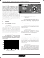
PQX-571 PQX-572 Parametric Equalizer Operating Manual ASHLY AUDIO INC. 847 Holt Road Webster, NY 14580-9103 Phone: (716) 872-0010 Toll-Free: (800) 828-6308 Fax: (716) 872-0739 Internet: http://www.ashly.com/ Operating Manual - PQX 571 and PQX 572 Parametric Equalizer Table Of Contents 1 INTRODUCTION . . . . . . . . . . . . . . . . . . . . . . . . . . . . . . . . . . . . . . . . . . . . . . . . . . . . . . . . 3 2 UNPACKING . . . . . . . . . . . . . . . . . . . . . . . . . . . . . . . . . . . . . . . . . . . . . . . . . . . . . . . . . . . . 3 3 AC POWER . . . . . . . . . . . . . . . . . . . . . . . . . . . . . . . . . . . . . . . . . . . . . . . . . . . . . . . . . . . . . 3 4 CONNECTIONS . . . . . . . . . . . . . . . . . . . . . . . . . . . . . . . . . . . . . . . . . . . . . . . . . . . . . . . . . 4.1 Balanced . . . . . . . . . . . . . . . . . . . . . . . . . . . . . . . . . . . . . . . . . . . . . . . . . . . . . . . . . . . . 4.2 Unbalanced . . . . . . . . . . . . . . . . . . . . . . . . . . . . . . . . . . . . . . . . . . . . . . . . . . . . . . . . . . 4.3 Grounding . . . . . . . . . . . . . . . . . . . . . . . . . . . . . . . . . . . . . . . . . . . . . . . . . . . . . . . . . . . 3 3 3 4 5 CONTROLS . . . . . . . . . . . . . . . . . . . . . . . . . . . . . . . . . . . . . . . . . . . . . . . . . . . . . . . . . . . . . 5.1 Low Shelving Filter . . . . . . . . . . . . . . . . . . . . . . . . . . . . . . . . . . . . . . . . . . . . . . . . . . . 5.2 Parametric Filter . . . . . . . . . . . . . . . . . . . . . . . . . . . . . . . . . . . . . . . . . . . . . . . . . . . . . . 5.3 High Shelving Filter . . . . . . . . . . . . . . . . . . . . . . . . . . . . . . . . . . . . . . . . . . . . . . . . . . 5.4 Master Level . . . . . . . . . . . . . . . . . . . . . . . . . . . . . . . . . . . . . . . . . . . . . . . . . . . . . . . . . 5.5 Clip Indicator . . . . . . . . . . . . . . . . . . . . . . . . . . . . . . . . . . . . . . . . . . . . . . . . . . . . . . . . 4 4 4 5 5 5 6 TYPICAL APPLICATIONS . . . . . . . . . . . . . . . . . . . . . . . . . . . . . . . . . . . . . . . . . . . . . . 6.1 Connecting Into a Sound System . . . . . . . . . . . . . . . . . . . . . . . . . . . . . . . . . . . . . . . 6.2 General Tone Control . . . . . . . . . . . . . . . . . . . . . . . . . . . . . . . . . . . . . . . . . . . . . . . . . 6.3 Feedback Control . . . . . . . . . . . . . . . . . . . . . . . . . . . . . . . . . . . . . . . . . . . . . . . . . . . . . 6.4 Console Channel Equalization . . . . . . . . . . . . . . . . . . . . . . . . . . . . . . . . . . . . . . . . . . 6.5 Large Room Equalization . . . . . . . . . . . . . . . . . . . . . . . . . . . . . . . . . . . . . . . . . . . . . . 6.6 Small Room Equalization . . . . . . . . . . . . . . . . . . . . . . . . . . . . . . . . . . . . . . . . . . . . . . 6 6 6 6 7 7 7 7 THEORY . . . . . . . . . . . . . . . . . . . . . . . . . . . . . . . . . . . . . . . . . . . . . . . . . . . . . . . . . . . . . . . 7 8 TROUBLESHOOTING TIPS . . . . . . . . . . . . . . . . . . . . . . . . . . . . . . . . . . . . . . . . . . . . . 8 9 DIMENSIONAL DIAGRAM . . . . . . . . . . . . . . . . . . . . . . . . . . . . . . . . . . . . . . . . . . . . . . 8 10 SPECIFICATIONS . . . . . . . . . . . . . . . . . . . . . . . . . . . . . . . . . . . . . . . . . . . . . . . . . . . . . . 9 11 WARRANTY INFORMATION . . . . . . . . . . . . . . . . . . . . . . . . . . . . . . . . . . . . . . . . . . . . 9 12 SCHEMATICS . . . . . . . . . . . . . . . . . . . . . . . . . . . . . . . . . . . . . . . . . . . . . . . . . . . . . . 10-11 - WARNING THIS APPARATUS MUST BE EARTHED 2 Operating Manual - PQX 571 and PQX 572 Parametric Equalizer 1. INTRODUCTION Congratulations on your purchase of an Ashly PQX series parametric equalizer. Like graphic equalizers, parametric equalizers allow you to boost or cut selected frequencies. Unlike graphic equalizers however, parametric equalizers can tune in the exact frequencies you want and control the bandwidth of each selected frequency band, resulting in very precise control of frequency response. The Ashly PQX series equalizers are a third generation design including many refinements on our original PQ models. Lower noise, greater headroom, additional filters, full 20Hz -20KHz range on all parametric filters and additional connector types are the result. The parametric filters are still based on the “state variable” type circuit, and a separate summing amplifier is used for each filter so that no interaction between bands occurs. 2. 4. AUDIO CONNECTORS AND CABLES 4.1 Balanced Ashly uses electronically balanced inputs on all equalizers. The inputs and outputs can be used balanced or unbalanced. Your PQX series equalizer is provided with three different connector types. 1/4 inch stereo phone UNPACKING As a part of our system of quality control, every Ashly product is carefully inspected before leaving the factory to ensure flawless appearance. After unpacking, please inspect for any physical damage. Save the shipping carton and all packing materials , as they were carefully designed to reduce to minimum the possibility of transportation damage should the unit again require packing and shipping. In the event that damage has occurred, immediately notify your dealer so that a written claim to cover the damages can be initiated. The right to any claim against a public carrier can be forfeited if the carrier is not notified promptly and if the shipping carton and packing materials are not available for inspection by the carrier. Save all packing materials until the claim has been settled. 3. fuse. In the unlikely event that the fuse should blow, refer the product to a qualified technician for servicing. Overall power consumption is less than 15 watts. AC POWER Your PQX equalizer should be connected to a standard 3-wire grounded electrical outlet supplying 120 Volts, 50-60 Hz (some export models are wired for 240 Volts, and are labeled as such). To reduce the risk of ground loop hum, connect all audio equipment to the same electrical power source. Removal of the ground pin is both unlawful and dangerous, as a potential shock hazard could result. This unit will perform normally within an AC voltage range of 94 to 130 volts. Voltages less than this, as found in “brown-out” conditions, will reduce headroom and decrease power supply regulation. While this may affect performance, the equalizer will continue to function during a brown-out. This unit has an internal line jacks, three pin XLR type connectors, and a terminal strip will allow interfacing to most professional audio products. The (+) signal is on the tip of the phone plug and pin 2 of the XLR connector. The (-) signal is on the ring of the phone plug and pin three of the XLR. To achieve best performance, we recommend using balanced connections between all components in your system, as this reduces ground-loop induced hum and common-modenoise. 4.2 Unbalanced If either inputs or outputs are used unbalanced, the signal is on the (+) connection and the (-) connection must be tied to ground. A mono phone plug used as an unbalanced connection will automatically ground the ring of the jack which is the (-) connection. When using a stereo plug, XLR connector, or the terminal strip for unbalanced input or output connections, the signal (-) MUST be tied to the sleeve, or a significant loss of signal level may result. 3 Operating Manual - PQX 571 and PQX 572 Parametric Equalizer 4.3 Grounding The terminal strip has two ground connections, one for input ground and one for chassis ground. The equalizer is shipped with a jumper strap connecting these two grounds. Normally, this strap should be left in place so the chassis and input grounds are connected. In a rack-mount installation where the equalizer is connected to other equipment with unbalanced inputs or outputs, and the rack itself provides a good electrical connection between the equalizer chassis and the other equipment, it may be desirable to remove this strap to isolate the input ground from chassis ground and avoid a ground loop. Unless you have such an installation and have a hum problem you can’t solve by other means (ie: using balanced input and output connections), leave the ground jumper strap in place. 5. CONTROLS 5.1 Low Shelving Filter (Filter No. 1) 1. Low Shelf Level The nature of a shelving filter is such that the frequency response ramps up to a plateau and then levels off again, hence the term “shelf”. This level control knob adjusts the boost or cut of the signal below the tuned filter frequency as selected by its outer concentric frequency knob. The level which is indicated on the panel dial is the decibel level of the flat portion of the shelf. (see drawing) 2. Low Shelf Frequency This control adjusts the frequency below which the shelving filter affects the level. The frequency which is indicated on the panel dial is the midpoint of the shelf’s sloping response. 5.2 Parametric Filters (Filters No. 2-6) 1. Range Switch Each parametric filter has a normal center frequency range of 200Hz-20KHz. Depressing the range switch divides the center frequency by 10, providing a range of 20Hz-2KHz. 2. Level Control The band of frequencies selected by the frequency and bandwidth controls are increased or decreased up to 15dB by this control. 3. Frequency Control This outer concentric knob adjusts the center frequency of the filter action. Tick marks on the face panel are calibrated to ISO 1/3 octave center frequencies. 4. Bandwidth Control This inner concentric Knob allows control of the width of frequencies around the center frequency (sometimes called “Q”), and is a key reason parametric equalizers are such a precise tool. With it, you can affect a wide (3.3 octaves) response, or a narrow (.05 octaves) band. To give an example, you could effectively boost or cut by 15dB a middle C on the piano without affecting the adjacent B or D at all! 5. EQ In/Out Switch Low Shelf Level Response 4 The individual filter is engaged by depressing this switch. Since the filter is bypassed when the EQ switch is out, it is recommended that the EQ switch be out when no filter action is required. This is preferable to “zeroing” the level control when considering optimum noise performance. Operating Manual - PQX 571 and PQX 572 Parametric Equalizer High Shelf Level Response Parametric Filter Level Control 5.3 High Shelving Filter (Filter No. 7) These concentric controls work the same way as the low shelf controls described in (1) and (2) except the filter response starts at the center frequency selected and continues up in frequency. 5.4 Parametric Filter Frequency Control Master Level The overall gain of the equalizer is adjusted by this control. The master level gain stage is placed prior to any filter stages so that increasing the master level will not amplify filter noise. If the Master EQ switch is out, the level control has no affect. Signals are then simply routed through the equalizer at unity gain. 5.5 Clip Indicator This red LED illuminates when an amplifier in any of the filters comes within 3 dB of clipping, including those filters which are not engaged. The maximum signal level through the PQX equalizers is greater than +22 dBu. Parametric Filter Bandwidth Control 5 Operating Manual - PQX 571 and PQX 572 Parametric Equalizer Mixer PQX 571 Parametric Equalizer Compressor - Limiter Crossover Power Amplifier Typical Sound System Design 6. TYPICAL APPLICATIONS 6.1 Connecting Into a Sound System Typically an equalizer is used in a sound system which has a mixer or some other sort of preamplifier. In such cases, the equalizer normally should be connected after the mixer but before any electronic crossovers or limiters. The PQX equalizers are line level devices designed to operate at nominal +4 dBu signal levels; therefore, the equalizer should not be connected directly to microphones, phonograph players or low level musical instruments. 6.2 General Tone Control The parametric equalizer is a very useful device for general tone shaping because the filter’s center frequency, bandwidth and level are all continuously variable. To use the power of the equalizer effectively, you need to translate your idea of the tone you want to produce into a range of numerical frequencies. This is simple after a little practice. Here are a few references which are useful for starting points: Very low bass (the “wind” in a kick drum, almost felt as much as heard -40Hz-80Hz. The low register of a male voice - 200Hz The low register of a female voice - 350Hz 6 Lower midrange (“warmth” frequencies) 400Hz-1KHz Upper midrange (“harshness”, snare drum “bite”, “hot” sound) -2.5KHz-4KHz. Sibilance (“sss” sounds, cymbal “sizzle”) - 8KHz15KHz. Try using these starting points as a guide when you want more or less of these types of sounds. Adjust by ear from there. It is always a good idea to remember that a little equalization usually works out much better than a lot, and that there are many audio problems which cannot be solved with equalization alone. 6.3 Feedback Control The PQX equalizers are powerful tools when applied to eliminating feedback problems. On a traditional graphic equalizer, the fixed filter center frequencies are insufficient when the frequency of feedback occurs between two slide faders, or is extremely narrow. The continuously variable center frequency and bandwidth of a parametric equalizer allows very sharp notching of feedback frequencies. The following procedure outlines how to use a parametric equalizer to suppress feedback frequencies: 1. Start with all the PQX EQ switches out except the master EQ switch in and the master Level at 0. Operating Manual - PQX 571 and PQX 572 Parametric Equalizer 2. With the entire PA hooked up and turned on, slowly increase the sound level at the mixer until feedback is heard, then lower the level by about 3 dB so that feedback does not continue. 3. Start with one of the PQX filters by setting the level at 0, bandwidth set fairly sharp (about .3 oct.), and adjust the frequency control to where you estimate the predominate feedback frequency to occur. 4. Push in the filter’s EQ switch and increase its level control by about +6 dB. Now “sweep” the frequency around where you have estimated the feedback frequency until feedback occurs. Once you have induced the feedback by boosting its frequency, quickly turn down the filter’s level control to about -6 dB to suppress or “notch out” the feedback frequency. 5. Again slowly increase the master level at the mixer until feedback is heard. If a new feedback frequency is heard, then repeat step 3 to find and suppress the new frequency. If the original feedback frequency is still heard, then adjust the first filter’s level even lower. The bandwidth control may be adjusted full clockwise to produce a very sharp notch so that a severe feedback frequency can be attenuated by as much as 15 dB without degrading the frequency response with noticeable notches. Note: Very sharp bandwidth lowers the maximum equalizer input level because of the high filter gain necessary to obtain such a narrow bandwidth. Only use bandwidth control full CW (.05 Octave) in severe cases. 6. Continue this iterative process of increasing the mixer’s master level and finding, then suppressing feedback frequencies until a desired sound system gain-before-feedback level has been achieved. 6.5 Large Room Equalization Large rooms tend to suffer from multiple reflections with long time delays, long reverberation times, and “ring-modes”, all of which lead to reduced intelligibility and a generally “muddy” sound. As sound travels long distances through the air, high frequencies are attenuated more than low frequencies. In general, large rooms benefit from some low frequency shelf roll-off, high frequency shelf boost, and attenuation of ring mode frequencies by the parametric filters. 6.6 Small Room Equalization Small rooms need less equalization than large ones. However, with reflective surfaces so close together it is more likely to encounter high frequency feedback problems. Finding and critically notching out these offending “hot spots” is precisely what the PQX equalizer does best. Use the narrowest possible bandwidth, and as always, avoid over-equalization. 7. THEORY The heart of the PQX equalizers is a unique bandpass filter circuit. Basically a “state-variable” type, this filter is trimmed and optimized to provide excellent transient response and a wide range of frequency and bandwidth adjustment. Each filter can be tuned over a 100:1 frequency range (about 6.6 octaves) and a 70:1 bandwidth range with no more than a 2 dB amplitude error at center frequency. At its sharpest setting, the filter has a “Q” of about 35 and generates a response curve with 3 dB points only 1/20 octave apart, making feedback control possible with no audible side effects. Each filter is placed in the feedback loop of a summing amplifier to produce the desired frequency response. Since a separate summing amplifier is used for each band, no interaction between bands occurs. + - 6.4 OUT BALANCED INPUT Console Channel Equalization GAIN OUTPUT EQ CLIP IN PEAK DETECTOR Many mixing consoles provide only simple equalization for individual channels. If your console has channel inserts, you can patch your equalizer into a channel that is used for something important, and use it to tailor the sound of this channel exactly the way you want. EQ IN LOW SHELF FILTER FR EQ IN EQ IN EQ IN EQ IN EQ IN PAR. FILTER 20-20K PAR. FILTER 20-20K PAR. FILTER 20-20K PAR. FILTER 20-20K PAR. FILTER 20-20K FR +/- Q +/- FR Q +/- FR Q +/- FR Q +/- FR EQ IN HIGH SHELF Q +/- FR +/- PQX Block Diagram 7 Operating Manual - PQX 571 and PQX 572 Parametric Equalizer 8. TROUBLESHOOTING TIPS 8.5 8.1 No Output Hum will usually be caused by a “ground loop” between components. Try using the suggested balanced input and output connections if the other pieces of equipment used in conjunction with your equalizer have balanced inputs and outputs. Noise (too much hiss) can be caused by insufficient drive signal. Make sure you are sending a nominal 0 dBu line level signal to the equalizer. Check AC power - is the Power LED on? Check in/out connections -are they reversed? Are you sure you have an input signal? 8.2 Eq Controls Do Nothing Is the master EQ in/out switch in? Maybe the bandwidth setting is too sharp to produce an audible change. The center frequency and bandwidth controls do not have an effect if the level control is set at “0”, or if the in/out switches are switched out. 8.3 Clip Light Flashes or Stays On If the clip light flashes, the signal level to the equalizer is too high. Turn down the level on the unit feeding the PQX equalizer. If the clip LED is on all the time, disconnect the input and output cables. If it is still on, the unit must be returned for service. 8.4 Distorted Sound Excessive Hum or Noise The input ground to chassis ground jumper strap supplied with the equalizer should normally be left in place to minimize ground loop voltage and for safety reasons. If hum or buzz noise is still heard after you have installed balanced input and output connections using good quality shielded cable, the ground strap may be removed to reduce hum caused by ground loop current. Note: unshielded cables, improperly wired connections, and cable with broken strands (shorts, etc.) are the most common problems. Make sure you use good quality cable with connectors soldered firmly on the correct pin. When in doubt, get in touch with your Ashly dealer, or call the factory direct - (800) 828-6308. This will only be caused by too much signal which will show on the clip light. If the light is not flashing, there is an overload somewhere else in the signal chain. Adjust the gain of each component in your signal chain until the unit which is distorting is found. 9. 8 DIMENSIONAL DIAGRAM Operating Manual - PQX 571 and PQX 572 Parametric Equalizer 10. SPECIFICATIONS (0 dBu = 0.775 volts rms, Balanced input) 10.1 Master Gain Level: 10.12 ±15dB 10.2 Peak Filter Amplitude: 10.3 Peak Filter Frequency Range Range Switch Out 200Hz - 20KHz ±15dB 10.13 Range Switch In: 10.4 20Hz - 2KHz 10.14 Peak Filter Bandwidth: 3 1/3 - 1/20 octave 10.5 Shelving Filter Frequency Ranges (At midpoint of shelving slope) Low: 40Hz - 400Hz High: 1.6KHz - 16KHz 10.14 10.15 10.6 Shelving Filter Amplitude: (At flat portion of shelving response) ±15dB 10.7 Input Impedance: 20KΩ active balanced 10KΩ unbalanced 11. Hum and Noise: (20Hz - 20KHz, unweighted, all controls at unity gain) EQ Out -109dBu EQ In, peaking filters in -93dBu EQ In, peaking and shelving filters in -90dBu Power Requirements: (240 VAC Available) 94 - 130VAC 50-60Hz Power Consumption: 15W Size: PQX 571: PQX 572: 19"L x 1.75"H x 6"D 19"L x 3.5"H x 6"D Shipping Weight PQX 571: PQX 572: 8 lbs. 10 lbs. WARRANTY INFORMATION We thank you for your expression of confidence in Ashly products. The unit you have just purchased is protected by a full five year warranty. To establish the warranty, be sure to fill out and mail the warranty card attached to your product. 10.8 Output Impedance: (Terminate with 600Ω or more) 200Ω balanced 100Ω unbalanced 10.9 Maximum Input Level: All filters in All level controls at unity gain +23dBu One peak filter at max boost Bandwidth control .3 octave or greater +7dBu Please fill out the information below for your records, and have it ready should you need to contact ASHLY or one of its dealers. 10.10 Frequency Response: Dealer ________________________________________ 10.11 Distortion: (THD, +4dBu, 20Hz - 20KHz) < .03% 20Hz - 20KHz ±.2dB Model Number _________________________________ Serial Number _________________________________ Date of Purchase _______________________________ Dealer’s Address _______________________________ ______________________________________________ Dealer’s Phone _________________________________ Salesperson ____________________________________ 9 Operating Manual - PQX 571 and PQX 572 Parametric Equalizer SCHEMATICS PQX 571, PQX 572 Schematic Diagram 1 of 2 12. 10 Operating Manual - PQX 571 and PQX 572 Parametric Equalizer PQX 571, PQX 572 Schematic Diagram 2 of 2 11 Operating Manual - PQX 571 and PQX 572 Parametric Equalizer ASHLY AUDIO INC. 847 Holt Road Webster, NY 14580-9103 Phone: (716) 872-0010 Fax: (716) 872-0739 Toll Free (800) 828-6308 Internet: http://www.ashly.com/ 1997 by Ashly Audio Corporation. All rights reserved worldwide. Printed in USA 5/97 PQX Rev 2