1
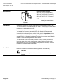
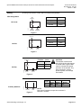
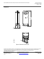
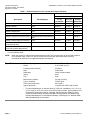
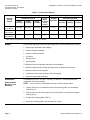
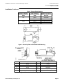
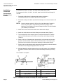
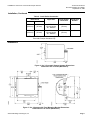
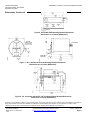
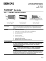
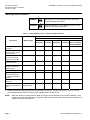
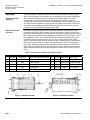
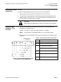
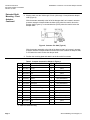
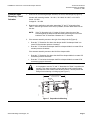
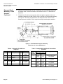
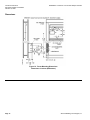
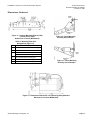
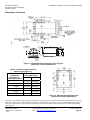
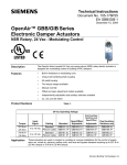
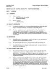
Technical Instructions
Document No. 155-746
EA GND-1
March 17, 2005
OpenAir™ GND Series Electronic Damper Actuator
UL Listed Fire/Smoke and Smoke Control Dampers
2-Position, 15-second Run Time,
15-second Spring Return Time
N474
Description
The OpenAir™ direct coupled, fast-acting, two-position, spring return electronic actuators
are available as 24 Vac/dc, 120 Vac, and 230 Vac models. They are intended for use on
UL listed smoke control dampers and combination fire/smoke rated dampers.
Features
•
Optional built-in auxiliary switches: Fixed switch points at 5° and 85 ° rotation.
•
Optional built-in Electronic Fusible Link (EFL) capability with four temperature
ratings: 165°F (74°C), 212°F (100°C), 250°F (121°C), 350°F (177°C).
•
Reversible fail-safe spring return.
•
All metal housing.
•
Pre-cabled Teflon® insulated lead wires.
•
Fifteen-second operation at rated torque, temperature and voltage.
Application
This actuator is used for the control of dampers requiring up to 53 lb-in (6Nm) driving
torque. It is intended for control of UL listed smoke control dampers and combination
fire/smoke HVAC dampers. This actuator is designed to meet the 2002 revisions to the
UL 555/555S and the AMCA Standard 520 specifications.
Siemens Building Technologies, Inc.
Technical Instructions
Document No. 155-746
March 17, 2005
OpenAir GND Series Electronic Damper Actuator UL Listed Fire/Smoke Control Dampers
Product Numbers
G
Direct-coupled Electronic Fire and Smoke Damper Actuator
N Spring Return 53 lb-in (6 Nm)
D
15 second run time
1 24 Vac/dc
2 120 Vac
3 230 Vac
2 2-position
1 Standard version
6 Two auxiliary switches
.1 Fire and smoke shaft adapter
U Assembled in USA
/B Bulk pack 10
/F Electronic Fusible Link (EFL) connection
/F/B EFL connection and bulk pack 10
Warning/Caution Notations
WARNING
CAUTION:
Service
Personal injury/loss of life may occur if you do
not perform a procedure as specified.
Equipment damage may occur if you do not
perform a procedure as specified.
WARNING:
Do not open the actuator. Personal injury may occur if opened. Opening the
actuator voids the warranty.
If the actuator is inoperative, replace the unit.
Page 2 of 7
Siemens Building Technologies, Inc.
OpenAir GND Series Electronic Damper Actuator UL Listed Fire/Smoke Control Dampers
Specifications
Operating voltage
Frequency
Power consumption
running
holding
Power Consumption
running
holding
24 Vac ±20%
24 Vdc +20%, -10%
120 Vac ±10%
230 Vac ±10%
50/60 Hz
24 Vac/dc
20 VA/12W
8 VA/6W
120 Vac/230 Vac
20 VA
9 VA
Running torque
Stall torque (minimum)
Torque reduction at elevated temperature
Runtime for 90°
closing (on power loss) with spring return
Nominal angle of rotation
53 lb-in (6 Nm) (minimum)
160 lb-in (18 Nm)
Less than 10%
15 seconds nominal
15 seconds maximum
95°
Power supply
Function
Technical Instructions
Document No. 155-746
March 17, 2005
Minimum 35,000 full stroke cycles
Life Expectancy
Mounting
Damper shaft size
Damper shaft length, minimum
.5-inch (12,7 mm) round
1.4-inch (36 mm)
Housing
Enclosure
Material
NEMA 1
Die cast aluminum alloy
Ambient conditions
Operation
0°F to 140°F (-18°C to 60°C)
one time 350°F (177°C)
–40°F to 158°F (–40°C to 70°C)
Maximum 95% rh non-condensing
400°F (200°C)
Storage and transport
Ambient humidity (non-condensing)
Teflon® cable
UL873
cUL C22.2 No. 24-93
AS/NZS 2064 1/2:1997
Conforms to CE requirements for the
EMC and low voltage directives
Australian Electromagnetic
Compatibility (EMC) per AS/NZS
4251.1/2:1999 (C-tick)
Agency certification
Miscellaneous
Pre-cabled connection
Dimensions
Weight
Siemens Building Technologies, Inc.
18 AWG, 3 feet (.9 meter)
3/8-in (.5mm) flexible conduit connector
9-in. × 3.25-in. × 3-in. D
(229 mm × 83 mm × 76 mm)
≈4 lb (1.8 kg)
Page 3 of 7
Technical Instructions
Document No. 155-746
March 17, 2005
OpenAir GND Series Electronic Damper Actuator UL Listed Fire/Smoke Control Dampers
Accessories
EA1127R1
Electronic Fusible Link (EFL)
ASK79.165 (165°F (74°C) operation)
ASK79.212 (212°F (100°C) operation)
ASK79.250 (250°F (121°C) operation)
ASK79.350 (350°F (177°C) operation)
NOTE:
Determine and order
appropriate actuator before
selecting EFL.
Figure 1.
Operation
When power is applied, the actuator coupling moves toward the open position, "90°".
The actuator opens in 15 seconds nominal, 90° at 60 Hz. In the event of a power failure
or when operating voltage is turned off, the actuator returns to the "0" position. The
return time is 15 seconds nominal for 90°.
The National Fire Protection Association NFPA 92A Standard for Recommended
Practice for Smoke-Control System and UL 864 Standard for Control Units and
Accessories for Fire Alarm Systems, require weekly self-tests for dedicated smoke
control equipment used in a smoke control system. The National Fire Protection
Association NFPA 72 Standard for National Fire Alarm Codes states that all life-safety
systems are to be functionally checked at least annually.
The GND actuator does not require any periodic cycling to function properly as an
integral part of an active smoke control damper system. Check the smoke control
damper/actuator every time you functionally check your smoke detectors, emergency
lights, and/or power generators for operation.
Installation
Refer to the installation instructions for detailed guidelines. (See 129-402)
CAUTION:
Read and carefully follow the Installation Instructions to avoid equipment
damage.
Page 4 of 7
Siemens Building Technologies, Inc.
OpenAir GND Series Electronic Damper Actuator UL Listed Fire/Smoke Control Dampers
Wiring
Technical Instructions
Document No. 155-746
March 17, 2005
All wiring must conform to NEC and local codes and regulations.
Wire Designations
RED
(SUPPLY)
Function
Color
Supply
Red
Neutral
Black
Ground
Green
Function
Color
Line
Black
Neutral
White
Ground
Green
24 Vac/dc
EA0941R1
M
BLACK
(NEUTRAL)
GREEN
(GROUND)
Figure 2.
BLACK (Line)
M
EA1167R2
120 Vac
WHITE
(Neutral)
GREEN
(Ground)
Figure 3.
BROWN (Line)
M
EA0609R2
230 Vac
BLUE
(Neutral)
Function
Color
Line
Brown
Neutral
Blue
Ground
Green
CAUTION:
The actuator must be wired
with a 230 Vac line with respect
to neutral and the ground lead
must be connected for proper
protection of the actuator. Any
other connection, such as
phase-to-phase, can damage
the actuator.
GREEN
(Ground)
Figure 4.
85∞
5∞
Switch
Auxiliary Switches
EA1163R2
5°
85°
YELLOW
GRAY
Figure 5.
Siemens Building Technologies, Inc.
Wire
Color
Gray
Yellow
Switch
Makes
< 5°
> 85°
Switch
Breaks
> 5°
< 85°
NOTE:
Both sets of contacts are open when actuator is
between 5° and 85°.
Page 5 of 7
Technical Instructions
Document No. 155-746
March 17, 2005
OpenAir GND Series Electronic Damper Actuator UL Listed Fire/Smoke Control Dampers
Wiring, Continued
EA1165R1
NOTE:
When ordered, GND
Electronic Fusible Link
models come pre-wired
for coupling with EFL
sensor.
EA1166R1
Molex connector
for use with
Siemens
EFL 7.
Figure
Figure 6.
Page 6 of 7
Siemens Building Technologies, Inc.
OpenAir GND Series Electronic Damper Actuator UL Listed Fire/Smoke Control Dampers
Technical Instructions
Document No. 155-746
March 17, 2005
Dimensions
.8
(200,1)
MANUAL
OVERRIDE
1.2
(30)
1.2
(30)
EA1148R1
3.2
(81)
.99
(25.1)
.8
(19,2)
.8
(19,2)
Figure 8. Dimensions in Inches (mm).
Information in this publication is based on current specifications. The company reserves the right to make changes in specifications and models as
design improvements are introduced. Teflon is a registered trademark of DuPont. OpenAir is a registered trademark of Siemens Building
Technologies. Other product or company names mentioned herein may be the trademarks of their respective owners.
© 2005 Siemens Building Technologies, Inc.
Siemens Building Technologies, Inc.
1000 Deerfield Parkway
Buffalo Grove, IL 60089-4513
U.S.A.
Your feedback is important to us. If you have
comments about this document, please send
them to [email protected]
Document No. 155-746
Country of Origin: US
Page 7 of 7
Technical Instructions
Document No. 152-046P25
EA GGD-1
January, 9 2008
OpenAir™ GGD Electronic Damper Actuator
Designed for UL Listed Fire/Smoke and
Smoke Control Dampers
2-Position, 15-second Runtime
15-second Spring Return Time
N474
Description
The OpenAir™ direct coupled, fast acting, two-position, spring return electronic actuators
are available as 24 Vac, 115 Vac, and 230 Vac models. They are intended for use on UL
listed smoke control dampers or combination fire/smoke rated dampers.
Features
•
High temperature rated drive system.
•
Reversible fail-safe spring return.
•
All metal housing.
•
Teflon® insulated lead wires.
•
Mechanical range adjustment.
•
Multiple shaft couplings available; will accommodate up to 1.05-inch shafts.
•
Fifteen second nominal open time; 15-second nominal spring return time.
Application
This actuator is used for the control of dampers requiring up to 142 lb-in (16Nm) driving
torque. It is intended for control of UL listed smoke control dampers or combination
fire/smoke HVAC dampers. This actuator is designed to meet the 1999 revisions to the
UL 555S and AMCA 500-D specifications. Minimum stall torque 350 lb-in.
Table 1.
Product Numbers
Type
Rotation
Standard
95°
Eight pack of standard
With oversize shaft adapter
Shaft Adapter
24 Vac
115 Vac
230 Vac
Self-centering
GGD121.1U
GGD221.1U
GGD321.1U
95°
Self-centering
GGD121.1U/B
GGD221.1U/B
GGD321.1U/B
95°
Oversized
GGD121.3U
GGD221.3U
GGD321.3U
Siemens Building Technologies, Inc.
Technical Instructions
Document No. 152-046P25
January 9, 2008
Specifications
GGD Electronic Damper Actuator Designed for UL Listed Fire/Smoke Control Dampers
Operating voltage
24 Vac ±20%
115 Vac ±15%
230 Vac ±10%
50/60 Hz
Power supply
Frequency
Power consumption
running
holding
Function
150 VA
10 VA
Running torque
Spring return torque
Minimum stall torque
Torque reduction at elevated temperature
Runtime for 90°
operating with motor at 60 Hz
closing (on power loss) with spring return
Nominal angle of rotation
142 lb-in (16 Nm)
108 lb-in (12 Nm)
350 lb-in (39 Nm)
Less than 10%
15 seconds nominal
15 seconds maximum
95°
Minimum 35,000 full stroke cycles.
Life Expectancy
Damper shaft size
Standard
Oversize
Minimum shaft length
3/8 to 1 inch (8 to 25.6 mm)
1.05 inch maximum (26.6 mm)
3/4-inch (20 mm)
Housing
Enclosure
Material
NEMA 1
Die cast aluminum alloy
Ambient conditions
Ambient temperature
operation
Mounting
storage and transport
Ambient humidity (non-condensing)
UL listed to UL873
cUL certified to Canadian standard
C22.2 No. 24-93
Australian EMC Framework (C-tick)
with the limits per
AS/NZS 2064 1/2:1997
Agency certification
Miscellaneous
0 to 130°F (-18 to 55°C)
One time 350°F (177 °C)
for 1/2 hour (per UL555S)
-25 to 158°F (-32 to 70°C)
Maximum 95% R.H.
Pre-cabled connection
Dimensions
18 AWG
See Figure 1.
Weight
≈7 lbs. (3.2 kg)
Eight pack
≈56 lbs. (25.4 kg)
Warning/Caution Notations
WARNING
CAUTION:
Page 2 of 4
Personal injury/loss of life may occur if you do
not perform a procedure as specified.
Equipment damage may occur if you do not
follow a procedure as specified.
Siemens Building Technologies, Inc.
GGD Electronic Damper Actuator Designed for UL Listed Fire/Smoke Control Dampers
EA0500R1
Accessories
Technical Instructions
Document No. 152-046P25
January 9, 2008
ASK74.1 Oversized shaft
985-004
Self-centering shaft adapter will accommodate
adapter.
up to a 1.05-inch (26.6 mm)
diameter shaft. Use for
coupling to 1-inch
jackshafts that are slightly
oversized.
Operation
EA1059R1
EA0653R1
985-006 Anti-rotation (mounting) bracket.
985-035P25 Conduit
adapter for accommodating a conduit
box (pk of 25).
985-008P20 Conduit
adapter for a 1/2-inch
(12 mm) NPT
connector (pk of 20).
When power is applied, the actuator coupling moves toward the open position, “90°”.
The actuator opens in fifteen seconds nominal, 90° at 60 Hz. In the event of a power
failure or when operating voltage is turned off, the actuator returns to the “0” position.
The return time is fifteen seconds maximum for 90°.
The GGD actuator does not require any periodic cycling to function properly as an
integral part of an active smoke control damper system.
NOTE:
Installation
Siemens Building Technologies, Inc. however, strongly suggests that all
life safety systems are functionally checked periodically. Check the
smoke control damper/actuator every time you functionally check your smoke
detectors, emergency lights, and/or power generators for operation.
Refer to the installation instructions for detailed guidelines.
CAUTION:
Read and carefully follow the Installation Instructions (129-255) to avoid
equipment damage.
Wiring
All wiring must conform to NEC and local codes and regulations.
RED (G)
Wire Designations
24 Vac
EA0550R1
M
Function
Color
Supply (SP)
Neutral (SN)
Red
Black
Ground
Green
Function
Line
Neutral
Ground
Color
Black
White
Green
BLACK (G0) GREEN (GND)
BLACK (Line)
115 Vac
EA0549R2
M
Siemens Building Technologies, Inc.
WHITE
(Neutral)
GREEN
(Ground)
Page 3 of 4
Technical Instructions
Document No. 152-046P25
January 9, 2008
GGD Electronic Damper Actuator Designed for UL Listed Fire/Smoke Control Dampers
BROWN (L)
Wire Designations,
continued
230 Vac
EA0609R1
M
BLUE (N)
Function
Color
Line
Neutral
Ground
Brown
Blue
Green
CAUTION:
The actuator must be wired
with a 230 Vac line with respect
to neutral and the ground lead
must be connected for proper
protection of the actuator. Any
other connection, such as
phase to phase, can damage
the actuator.
GREEN (GND)
WARNING:
Service
Do not open the actuator. Personal injury may occur if opened. Opening
the actuator voids the warranty.
If the actuator is inoperative, replace the unit.
Dimensions
105˚ OP
TIO
NA
L
95˚
min. 4 in.
100 mm
1-1/8 in.
28 mm
11 in.
279 mm
3-3/8 in.
86 mm
min. 8 in.
min. 1/4 in.
7 mm
200 mm
7-3/4 in.
197 mm
1-11/32
1-19/32
34 mm
37 mm
3-15/16 in.
min. 2-1/2 in.
60 mm
100 mm
EA0548R2
OPENING
FOR 3/8"
FLEX CONDUIT
1-23/32 in.
30 mm
Figure 1. Dimensions of the Actuator.
Information in this publication is based on current specifications. The company reserves the right to make changes in specifications and models as
design improvements are introduced. Teflon is a registered trademark of DuPont. OpenAir is a trademark of Siemens Building Technologies.
Product or company names mentioned herein may be the trademarks of their respective owners. © 2008 Siemens Building Technologies, Inc.
Siemens Building Technologies, Inc.
1000 Deerfield Parkway
Buffalo Grove, IL 60089-4513
U.S.A.
Your feedback is important to us. If you have
comments about this document, please send
them to [email protected]
Document No. 152-046P25
Country of Origin: US
Page 4 of 4
Technical Instructions
Document No. 155-146P25
AP 331-1
September 18, 2008
POWERS™ Controls
No. 3 Pneumatic Damper Actuator
331-4312 Pivot Mounting
331-4313 Fixed Mounting
331-4311 Extended Shaft Mounting
Description
The POWERS Controls No. 3 Pneumatic Damper Actuator is a compact, totally
enclosed, rolling diaphragm-type actuator designed for modulating or two-position
actuation of dampers or air valves.
Features
• All metal body construction
• Totally enclosed to protect internal parts
• Variety of spring ranges for sequencing
• Fixed or pivot mounting models
• Pivot mounting for extended shaft
• Positioning relay (optional)
• Variety of mounting/linkage kits for special applications
• Threaded shaft for easy mounting to accessory thread
Product Numbers
See Table 1.
Application
Typical applications are for control of mixing box dampers or air valves, and damper
control for unit ventilators, unit conditioners and other HVAC applications.
These compact, totally enclosed actuators are easily installed either directly within the
mixing box or unit enclosure, or externally, as required for each application.
Siemens Building Technologies, Inc.
Technical Instructions
Document Number 155-146P25
September 18, 2008
POWERS™ Controls No. 3 Pneumatic Damper Actuator
Table 1. Product Numbers for No. 3 Pneumatic Damper Actuators.
Part No.
Nominal Spring Range
Mounting Style
Description
3-7 psi
(21-48 kPa)
5-10 psi
8-13 psi
(35-69 kPa) (55-90 kPa)
Actuator
Front
331-4310
331-4510
331-4810
Actuator, bracket
Fixed
331-4313
331-4513
331-4813
Actuator, bracket, clevis
Fixed
331-4314
331-4514
331-4814
Actuator, integral pivot
Pivot
331-4312
331-4512
331-4812
331-4311
331-4511
331-4811
Actuator, integral pivot with pivot post * Extended shaft
Actuator, integral pivot with pivot post * Extended shaft kit with positioning
relay
Actuator, bracket, ball joint connector
Fixed
Actuator, bracket, ball joint connector
and positioning relay
Fixed
—
—
331-4331
—
331-4531
—
332-4811
331-4831
332-4831
Extended shaft with 90° barb fitting (for Extended shaft
—
—
546-00020
fume hood controller applications)
* Mounted on plate for extended shaft with clevis and crank for 3/8-inch (10-mm), 7/16-inch (11-mm), or 1/2-inch
(13-mm) diameter shaft.
NOTE:
When the actuator is ordered with extended shaft mounting, the mounting plate, pivot post and hardware,
clevis, damper crank, rocker arm, and all screws/nuts are included. Order other frame mounting
accessories as required if not supplied by damper manufacturer.
Specifications
Effective diaphragm area
Stroke
Housing (totally enclosed)
Stem
Diaphragm
Spring
Cup
Maximum air pressure
Type of mounting
Thrust and torque rating
Agency Approvals
*
Page 2
8 inches2 (51.6 cm2)
2-3/8 inches (6 mm) *
Aluminum
Plated steel
Ozone resistant rubber
Steel
Zytel
30 psig (210 kPa)
Fixed or pivot
See Table 3
Complies with UL555 and UL555S
For special applications, an actuator stroke of 2-3/4 inch is available in 3 to 7, 5 to 10,
or 8 to 13 psi (21 to 58, 35 to 69, or 55 to 90 kPa) spring ranges. Some models are UL
Recognized Components under UL’s Damper Actuator category (EMKU2), which
covers pneumatic damper actuators intended to be employed on fire dampers and
leakage rated dampers. Contact Siemens Building Technologies, Inc. National OEM
Sales and Marketing for information.
Siemens Building Technologies, Inc.
POWERS™ Controls No. 3 Pneumatic Damper Actuator
Specifications,
Continued
Nominal spring ranges
Operating
Operating temperature
Air connection
Miscellaneous
Shipping Weight:
Basic actuator
Actuator with extended shaft mounting
Actuator with fixed bracket
Actuator with fixed bracket and clevis
Actuator with extended shaft mounting
and Positioning Relay
Dimensions
Technical Instructions
Document Number 155-146P25
September 18, 2008
3 to 7 psi (21 to 50 kPa)
5 to 10 psi (35 to 69 kPa)
8 to 13 psi (55 to 90 kPa)
-20°F to 160°F (-29°C to 71°C)
Straight barb fitting for 1/4-inch OD
plastic tubing installed in 1/8-inch NPT
opening
1.3 lb (0.58 kg)
3.1 lb (1.4 kg)
2.5 lb (1.1 kg)
2.7 lb (1.2 kg)
4.8 lb (2.2 kg)
See Figures 4 through 8
Accessories
Linkage kit, 4-inch link and crank
Linkage kit, 4-inch rod, ball joint and crank
Damper shaft crank, selectable radius, 45°, 60°, and 90°, angular
rotation for 3/8 to 1/2-inch (10 to 13-mm) diameter damper shafts
Damper shaft crank, adjustable radius 3/4 to 2-7/8 inch (19 to 73 mm)
for 1/2-inch (13-mm) diameter damper shafts
Damper shaft crank, adjustable radius 3/4 to 4-5/8 inch (19 to 177 mm)
for 3/8-inch (9 mm) diameter damper shafts
Damper shaft extension, 1/2 × 9 inches long
Damper shaft extension, 1/2 inch shaft
Damper shaft extension Adapter, for 3/8 inch shaft
Pivot mounting kit (bracket and three mounting screws)
Pivot post
Fixed mounting bracket
Extended shaft mounting plate
Clevis, steel
Clevis, forged
Clevis pin
Clevis, frame mounting
Hitch pin
12-inch Damper actuator push rod
15-inch Damper actuator push rod
18-inch Damper actuator push rod
24-inch Damper actuator push rod
36-inch Damper actuator push rod
48-inch Damper actuator push rod
Damper blade rocker arm
Positioning relay
Relay mounting kit
Siemens Building Technologies, Inc.
331-958
331-947
331-941
331-795
331-805
333-042
331-631
331-632
333-148
333-139
331-916
331-033
333-207
331-292
331-293
331-653
331-807
338-041
338-042
338-043
338-044
338-045
338-046
333-034
147-2000
147-104
Page 3
Technical Instructions
Document Number 155-146P25
September 18, 2008
POWERS™ Controls No. 3 Pneumatic Damper Actuator
Table 3. Thrust Torque Ratings.
Maximum Thrust lb. (N)
Nominal
Spring
Range
Torque Rating* lb-in (Nm)
Spring
Return
25 psi
(No Stroke)
(172 kPa)
0 psig
(0 kPa)
Full Stroke Forward
Gradual
Operation
2-Position Operation
15 psi
(103 kPa)
18 psi
(124 kPa)
25 psi
(172 kPa)
10 (1.1)
20.2 (2.3)
20.2 (2.3)
20.2 (2.3)
40 (178)
10 (1.1)
33.6 (3.8)
33.6 (3.8)
33.6 (3.8)
64 (285)
10 (1.1)
53.8 (6.1)
53.8 (6.1)
53.8 (6.1)
15 psi
(103 kPa)
18 psi
(124 kPa)
3 to 7 psi
(21 to 48 kPa)
64 (285)
88 (391)
144 (641)
24 (107)
5 to 10 psi
(35 to 69 kPa)
40 (178)
64 (285)
120 (534)
8 to 13 psi
(55 to 90 kPa)
16 (71)
40 (178)
96 (427)
* With maximum hysteresis of 2.5 psi (17.2 kPa) @ 90° rotation.
Sizing
The size and quantity of actuators required depends on several damper torque factors:
• Damper type (standard or low leakage)
• Quality of damper installation
• Number of damper sections
• Air velocity
• Static pressure
• Age of damper
To determine the correct actuator required for the installation:
• Obtain the damper torque ratings (lb-in/sq-ft) from the damper manufacturer.
• Determine the area of the damper.
• Calculate the total torque required to move the damper.
• Select the appropriate actuator(s).
Installation
Extended Shaft
Mounting, Pivot
Mounting
Page 4
For Actuators 331-4311, 331-4511, 331-4811, or 332-4811. These assemblies are
designed for 90° damper rotation.
NOTE:
Clevis mounts in Crank Radius Hole No. 6 for 90° damper rotation.
1.
Slip the 9/16-inch (14 mm) diameter hole in the mounting plate over the damper
shaft (Figure 1).
2.
Slip the crank over the 3/8 through 1/2-inch (10 through 13-mm) diameter damper
shaft (Figure 2).
3.
Position the mounting plate (Table 3).
4.
Attach the mounting plate to the duct with four screws.
Siemens Building Technologies, Inc.
POWERS™ Controls No. 3 Pneumatic Damper Actuator
Technical Instructions
Document Number 155-146P25
September 18, 2008
Installation, Continued
Table 3. Damper Blade Rotation.
Actuator Position in
Relation to Damper
Shaft
Crank Position in
Relation to Damper
Shaft
Rotation of Damper
Blade on Increase of
Pressure
Left
Above
Clockwise
Below
Counterclockwise
Above
Counterclockwise
Below
Clockwise
Right
Figure 1. Mounting Plate and Extended Shaft Mounting.
Item
Description
Item
Description
1
Nut(s)
6
Clevis
2
Lock Washers (2)
7
Hitch Pin
3
E-ring
8
Clevis Pin
4
Pivot Post
9
Crank Assembly Kit No. 331-941
5
Nut
10
Actuator Mounting Plate
Figure 2. Extended Shaft Mounting with Pivot.
Siemens Building Technologies, Inc.
Page 5
Technical Instructions
Document Number 155-146P25
September 18, 2008
Installation,
Continued
Extended Shaft
Mounting, Fixed
Actuator
POWERS™ Controls No. 3 Pneumatic Damper Actuator
For Actuators 331-4314, 331-4514, 331-4814 order Linkage Kit 331-958.
For Actuators 331-4313, 331-4513, 331-4813, order Clevis 333-207 and Linkage Kit
331-958.
1.
Determine the direction of the damper shaft rotation (clockwise or
counterclockwise) on an increase in pressure to the actuator.
2.
Determine the angle of rotation required for the damper to move from closed to full
open.
NOTE:
Since the actuator stroke is 2-3/8 inch (6 cm) and the angle of rotation is
known, the crank radius can be determined from the graph in TB181
Maximum Thrust Ratings of Pneumatic Damper Actuators Technical Bulletin
(155-219P25) or use Table 4.
3.
Attach the link to the crank at the radius value determined in Step 2.
4.
Attach the clevis and other end of the linkage to the actuator shaft (Figure 3).
5.
The normal position of the damper (open or closed) and its direction of rotation
(CW or CCW) will determine the location of the actuator and linkage assembly
(Table 3).
6.
Attach an air line or Baumanometer (squeeze bulb) to the actuator and increase
pressure until the actuator shaft moves one half of its stroke, 1-3/16 inch (3 cm).
Select the correct location for the actuator assembly as determined in Step 5.
7.
Slip the crank over the damper shaft and position the assembly so that the actuator
shaft and link are straight and perpendicular to the crank.
8.
Mark and attach the actuator bracket to the duct at this location. If this installation
procedure is followed, there will be no problem with linkage scissoring or locking
up.
The installation is complete.
Item
Description
Item
Description
1
Clevis Pin
4
Crank with Set Screw
2
Spring Washer
5
Hitch Pin
3
Washer, Nylon
6
Link, 4 inches (102 mm) long
Figure 3. Fixed Mounted Actuator Assembly with Linkage Kit 331-958.
Page 6
Siemens Building Technologies, Inc.
POWERS™ Controls No. 3 Pneumatic Damper Actuator
Technical Instructions
Document Number 155-146P25
September 18, 2008
Installation, Continued
Table 4. Crank Radius Connection.
Dimensions
Application
Crank Radius
Connection
Crank Hole
Number
X
Y
7-7/8 inch
(200 mm)
1-3/16 inch
(30 mm)
2-3/8 inch
(60 mm) stroke
90 ° Rotation
1-11/16 inch
(43 mm)
6
7-7/8 inch
(200 mm)
2-1/16 inch
(52 mm)
2-3/8 inch
(60 mm) stroke
60 ° Rotation
2-3/8 inch
(60 mm)
5
NOTE:
Crank Radius Holes No. 1 through 4 are used for No. 4 and No. 6
Pneumatic Damper Actuators only.
Dimensions
Figure 4. No. 3 Pneumatic Damper Actuator Dimensions.
Dimensions are in Inches (Millimeters).
Figure 5. No. 3 Actuator with Fixed Mounting Bracket Dimensions.
Dimensions are in Inches (Millimeters).
Siemens Building Technologies, Inc.
Page 7
Technical Instructions
Document Number 155-146P25
September 18, 2008
POWERS™ Controls No. 3 Pneumatic Damper Actuator
Dimensions, Continued
Figure 6. Extended Shaft Mounting Bracket Dimensions.
Dimensions are in Inches (Millimeters).
Figure 7. No. 3 Actuator with Pivot Mounting Bracket Dimensions.
Dimensions are in Inches (Millimeters).
Figure 8. No. 3 Actuator with the RL 147 Positioning Relay Mounted Dimensions.
Dimensions in Inches (Millimeters).
Information in this publication is based on current specifications. The company reserves the right to make changes in specifications and models as
design improvements are introduced. POWERS is a trademark of Siemens Building Technologies, Inc. Other product or company names
mentioned herein may be the trademarks of their respective owners. © 2008 Siemens Building Technologies, Inc.
Siemens Building Technologies, Inc.
1000 Deerfield Parkway
Buffalo Grove, IL 60089-4513
U.S.A.
Your feedback is important to us. If you have
comments about this document, please send them
to [email protected]
Document No. 155-146P25
Country of Origin: US
Page 8
Technical Instructions
Document No. 155-032P25
AP 331-2
October 10, 2005
POWERS™ Controls
No. 4 Pneumatic Damper Actuator
Actuator Assembly
331-2929 Typical
Actuator Assembly
331-2904 Typical
Actuator Assembly
331-3000 Typical
Description
The Powers Controls No. 4 Pneumatic Damper Actuator is a totally enclosed pneumatic
piston type actuator designed to operate dampers for ventilating systems, mixing box
control, and other applications requiring a large effective diaphragm area and long
stroke.
Features
•
All metal body construction
•
Replaceable, ozone-resistant, EPDM rubber, rolling diaphragm
•
Pivot mounting for extended shaft or frame mounting
•
Fixed bracket mounting
•
Direct front mounting
•
Positioning relay (optional)
•
Forward travel stops (optional)
•
Adjustable hesitation point (hesitation actuator only)
Product Numbers
See Table 1.
Application
The No. 4 Pneumatic Damper Actuator is recommended for control of outdoor, return
air, exhaust, face and bypass, fan discharge, and static pressure control dampers, as
well as specialized dampers and air valves found in terminal units such as unit
ventilators and mixing boxes.
Certain actuators in Table 1 are UL Recognized Components for fire/smoke
applications under category EMKU2. This category covers pneumatic
damper actuators used on fire dampers and leakage rated dampers.
The No. 4 Pneumatic Damper Actuator hesitation model is frequently used to operate
the outdoor air damper on unit ventilators. The hesitation feature enables the outdoor air
damper to be synchronized with the unit valve to maintain a predetermined outdoor air
requirement when the controlled zone is at the desired temperature.
Page 1
Technical Instructions
Document Number 155-032P25
October 10, 2005
POWERS™ Controls No. 4 Pneumatic Damper Actuator
Warning/Caution Notations
WARNING:
Personal injury, or loss of life may occur if you do not
follow a procedure as specified.
CAUTION:
Equipment damage, or loss of data may occur if you do
not follow a procedure as specified.
Table 1. Product Numbers for No. 4 Pneumatic Damper Actuator.
Product Numbers
Nominal Spring Range
Description
Mounting Style
3-7 psi
(21-48 kPa)
3-13 psi
(21-90 kPa)
5-10 psi
(35-69 kPa)
8-13 psi
(55-90 kPa)
2-3, 8-13 psi
(14-21, 55-90 kPa)
Hesitation Model
Actuator, mounting screws
(non-pivot)
Front
331-2910
—
331-2917
331-2963
—
Actuator, bracket
(non-pivot) 3-inch stroke
for unit ventilator
Fixed
331-2911
—
331-2934
331-2966
331-2927
Actuator, bracket
(non-pivot) 2-3/8 inch
stroke for unit ventilator
Fixed
—
—
—
—
331-2974
Actuator, mounting plate,
ball joint connector
Fixed
331-3015
331-3018
331-3016
331-3017
331-3019
Actuator, mounting plate,
ball joint connector with
positioning relay
Fixed
—
—
—
332-3017
—
Actuator, integral pivot
Pivot
331-2904 1
331-2905 1
331-2906 1
331-2961 1
331-2909 1
Actuator, integral pivot,
clevis and clevis pin for
use with frame mounting
accessory
Pivot
331-2929
331-2930
331-2931
331-2968
—
331-3000
331-3001
331-3002
331-2973 1
331-3004
—
—
—
332-2973
—
Actuator, integral pivot with Universal Kit
pivot post 2
Actuator, integral pivot with Universal Kit with
Positioning Relay
pivot post and positioning
relay 2
1
2
UL Recognized Components for Fire/Smoke Applications.
Mounted on plate for extended shaft with clevis and crank for 3/8-inch (10-mm), 7/16-inch (11-mm), or 1/2-inch
(13-mm) diameter shaft. Parts for frame mounting (blade drive) included with kit.
NOTE:
When the actuator is ordered with universal mounting, the mounting plate, pivot post and hardware, clevis,
damper crank, and all screws/nuts are included. Order other frame mounting accessories as required, if not
supplied by damper manufacturer.
Page 2
Siemens Building Technologies, Inc.
POWERS™ Controls No. 4 Pneumatic Damper Actuator
Specifications
Technical Instructions
Document Number 155-032P25
October 10, 2005
Effective diaphragm area
Stroke
Stroke (Hesitation model)
Stem
Housing
Diaphragm
Bearing
Maximum air pressure
Nominal spring ranges
Nominal spring range (Hesitation model)
Ambient temperature range
Operating
Storage
Air connection elbow barb fitting for
1/4-inch OD plastic tubing
Type of mounting
Thrust and torque rating
Dimensions
Agency Approvals
11 inches2 (71 cm2)
4 inches (102 mm)
3 inches (76 mm)
Stainless steel
Steel with cathodic epoxy electrocoat
Ozone-resistant, EPDM rubber
Oilite® sintered bronze bushing in
aluminum die casting
30 psig (210 kPa)
3 to 7 psi (21 to 50 kPa)
3 to 13 psi (21 to 90 kPa)
5 to 10 psi (35 to 70 kPa)
8 to 13 psi (55 to 90 kPa)
2 to 3; 8 to 13 psi
(14 to 21; 55 to 90 kPa)
-20°F to 200°F (-29°C to 93°C)
-20°F to 200°F (-29°C to 93°C)
Installed in 1/8-inch NPT opening
Front, bracket, pivot
See Table 2
See Figure 14
Complies with UL555 and UL555S
Table 2. Thrust and Torque Rating.
Nominal
Spring
Range
3-7 psi
(21-50 kPa)
Maximum Thrust lb (N)
Torque Rating* lb-in (Nm)
Full Stroke Forward
2-position Operation or
Spring Return Gradual
with Positioner
(No stroke) Operation
0 psig (0 kPa)
15 psi
18 psi
25 psi
15 psi
18 psi
25 psi
(103 kPa) (124 kPa) (172 kPa)
(103 kPa) (124 kPa) (172 kPa)
88 (391) 121 (538) 198 (881)
33 (147)
30 (3.4)
46 (5.2) 46 (5.2)
46 (5.2)
3-13 psi
(21-90 kPa)
22 (98)
55 (245)
132 (587)
33 (147)
30 (3.4)
30 (3.4)
46 (5.2)
46 (5.2)
5-10 psi
(35-70 kPa)
55 (245)
88 (391)
165 (734)
55 (245)
30 (3.4)
77 (8.7)
77 (8.7)
77 (8.7)
8-13 psi
(55- 90 kPa)
22 (98)
55 (245)
132 (587)
88 (391)
30 (3.4)
123 (14)
123 (14)
123 (14)
2-3, 8-13 psi
(14-21, 55-90 kPa)
Hesitation model
22 (98)
55 (245)
132 (587)
22 (98)
23 (2.6)
—
—
—
* With maximum hysteresis of 2.5 psi (17.2 kPa) @ 90° rotation.
Siemens Building Technologies, Inc.
Page 3
Technical Instructions
Document Number 155-032P25
October 10, 2005
Accessories
Page 4
POWERS™ Controls No. 4 Pneumatic Damper Actuator
Linkage kits:
Crank and link (Figure 9)
Rod, ball joint, and crank
Pivot post, ball joint, and crank
Cranks - damper shaft:
5/8-inch (16 mm) diameter
3/4-inch (19 mm) diameter
1-inch (25 mm) diameter
Adjustable radius, 3/4 to 2-7/8 inch (20 to 73 mm) for
1/2-inch (13 mm) diameter damper shaft
Selectable radius (45°, 60°, or 90° rotation) for
3/8 to 1/2-inch (10 to 13 mm) diameter damper shaft
Clevis:
Forged
Steel plated
Damper shaft extension kits:
1/2-inch (13 mm) × 2-1/4 inch (54 mm) long (See TB 128)
1/2-inch (13 mm) × 9-inch (229 mm) long
Damper shaft extension kit adapter, 3/8-inch (9.5 mm)
Actuator shaft adapter, uses 1/2-inch NPT Pipe
Actuator shaft extensions:
10-1/8-inches (257 mm) long
Ball joint type, 12 inches (305 mm) long
Damper blade rocker arm
Damper push rods, 5/16 inch (8 mm) diameter:
12 inches (30 cm) long
15 inches (38 cm) long
18 inches (46 cm) long
24 inches (61 cm) long
36 inches (91 cm) long
48 inches (122 cm) long
Spring clamp (secures 1/4-inch OD poly tubing to barb-fitting
at higher control pressures or elevated temperatures)
Forward stroke stop kit
Adjustable 2-3/8 to 4 inches (60 to 102 mm)
Positioning relay
Positioning relay mounting kit
Universal mounting plate
3/4-inch hole in plate for damper shaft
1-inch hole in plate for damper shaft (use with 333-194)
Frame mounting lug
Offset mounting bracket
331-958
331-947
331-954
333-182
333-183
333-181
331-795
331-941
331-653
333-207
331-631
333-184
331-632
333-030
331-434A
331-674
333-034
338-041
338-042
338-043
338-044
338-045
338-046
531-833
331-939
147-2000
147-314
331-623
331-623A
331-569
333-176
Siemens Building Technologies, Inc.
POWERS™ Controls No. 4 Pneumatic Damper Actuator
Service Kit
Technical Instructions
Document Number 155-032P25
October 10, 2005
EPDM diaphragms (package of 5)
333-071
Figure 1. Actuator Jam Nut Location.
WARNING:
Do not remove the jam nut (Figure 1). Spring is under heavy load.
Repair by trained personnel only.
Actuator Selection
for Unit Ventilator
For specific unit ventilators, see Application Bulletins found in Section 36 of the
POWERS™ Controls Installed Applications Manual (144-004).
Actuator Sizing
The quantity of actuators required depends on several torque factors. To determine the
quantity of actuators required for the installation:
1. Obtain damper torque ratings (ft-lb/ft2) from the damper manufacturer.
2. Determine the area of the damper.
3. Calculate the total torque required to move the damper:
Total Torque = Torque Rating × Damper Area
4. Calculate the total quantity of actuators required:
Number of
=
Actuators
1
Total Damper Torque Required
SF1 × Actuator Torque (Table 2)
Safety Factor: When calculating the number of actuators required, a safety factor
should be included for unaccountable variables such as slight misalignments, aging of
the damper, etc. A suggested safety factor is 0.80 (or 80% of the rated torque).
See AB-300 Damper Actuator Sizing and Selection Application Bulletin in the HVAC
Systems/Controls Reference Data (125-1853) for additional sizing information. See
TB-181 POWERS™ Controls Maximum Thrust Ratings of Pneumatic Damper Actuators
Technical Bulletin (155-219P25) for additional torque requirements.
Figure 2. Hesitation Actuator Adjustment.
Siemens Building Technologies, Inc.
Page 5
Technical Instructions
Document Number 155-032P25
October 10, 2005
Operation
POWERS™ Controls No. 4 Pneumatic Damper Actuator
The air tubing from a controlling instrument connects to the actuator's upper housing.
With no control pressure to the actuator, the compression spring forces the diaphragm
and actuator shaft toward the upper housing, but is limited by the jam nut on the
actuator shaft. As the control pressure on the diaphragm increases, the spring
compression is overcome and the actuator shaft gradually moves outward. Conversely,
as control pressure decreases, the spring returns the shaft to the position at which the
air pressure on the diaphragm balances the spring tension. For each value of control
pressure there is a corresponding position of the shaft.
Standard Actuator
(Figure 3)
The branch or return pressure from the controlling instrument connects to the upper
housing of the actuator. With no branch pressure to the motor, the main spring forces
the actuator shaft toward the upper housing, but is limited by the jam nut on the actuator
shaft. As the branch pressure on the diaphragm increases from 0 to 2 psi (0 to 14 kPa),
the compressive force in the main spring prevents the actuator shaft from moving. As
the branch pressure increases from 2 to 3 psi (14 to 21 kPa), the force in the main
spring is overcome and the actuator shaft moves to its hesitation point. At the hesitation
point, the main spring seat is in contact with the retard spring seat. The compressive
force in the retard spring prevents further actuator shaft travel between 3 and 8 psi (21
and 55 kPa). Above 8 psi (55 kPa), the resisting force in the retard spring is overcome
and the actuator shaft moves to its maximum stroke between 8 and 13 psi (55 and 90
kPa).
Hesitation Actuator
(Figure 4)
Table 3. Construction Components (Figures 3 and 4).
Item Part No.
1 333-099
Material
Aluminum
2
333-071
EPDM
3
—
Steel
4
—
5
—
Zytel
6
—
—
Description
Item Part No. Material
Description
Upper housing with pivot ears
7 331-915 Music wire Retainer clip
Diaphragm (Package of 5)
8
—
Stl. tubing Spring guide
Lower housing
9
—
Music wire Hesitation spring
10
—
Steel
Cycle adjusting rod
11
041-100
Brass
10-32 Hex nut
Oil-tempered steel Spring
Bearing plate
Piston cup/stem
Figure 3. Standard Actuator.
Page 6
Figure 4. Hesitation Actuator.
Siemens Building Technologies, Inc.
POWERS™ Controls No. 4 Pneumatic Damper Actuator
Technical Instructions
Document Number 155-032P25
October 10, 2005
Hesitation Actuator Example:
Adjustment
To obtain an initial hesitation point after one inch (25 mm) of shaft travel.
1. Add air pressure to the actuator until shaft travel is one inch (25 mm).
2. Turn locknuts on cycle adjustment rods until they contact lower housing, then lock
together (Figure 4, Items 10 and 11). For initial hesitation point settings other than
one inch (25 mm), follow this same procedure.
CAUTION:
Make certain cycle adjustment nuts are even to ensure smooth operation.
Extended Shaft
Mounting - Pivot
Actuator
1. Order one of the following for extended shaft mounting. These assemblies are
designed for 90° damper rotation.
Actuator: 331-3000, 331-3001, 331-3002, 331-2973, or 331-3004
NOTE:
Clevis mounts in Crank Radius Hole No. 1 for 90° damper rotation.
2. Slip the 3/4-inch (19 mm) diameter hole in the mounting plate over the damper shaft
(Figure 5).
Table 4. Mounting Plate Hole Identification.
Hole
Used For
1
No. 6 Actuator extended shaft mounting
2
Not used
3
No. 4 Actuator extended shaft
No. 6 Actuator frame mounting NC
Figure 5. Actuator Mounting Plate 331-623.
Dimensions in Inches (Millimeters).
Siemens Building Technologies, Inc.
4
No. 6 Actuator frame mounting NO
5
No. 4 Actuator frame mounting NC
6
No. 4 Actuator frame mounting NO
Page 7
Technical Instructions
Document Number 155-032P25
October 10, 2005
Extended Shaft
Mounting - Pivot
Actuator,
Continued
POWERS™ Controls No. 4 Pneumatic Damper Actuator
3. Slip the crank over the 3/8 through 1/2-inch (10 through 13-mm) diameter damper
shaft (Figure 6).
With the actuator assembly to the left of the damper shaft, an increase in actuator
pressure rotates the damper blade clockwise (CW) when the crank is above the
damper shaft (Figure 6), or counterclockwise (CCW) when the crank is below the
damper shaft.
Figure 6. Actuator 331-3000 (Typical).
With the actuator assembly to the right of the damper shaft, an increase in actuator
pressure rotates the damper blade CCW when the crank is above the damper shaft,
or CW when the crank is below the damper shaft.
4. Position the mounting plate and attach it to the duct with four screws.
Table 5. Actuator Accessories Shown in Figure 6.
Item
1
Part No.
Description
331-565 Pivot shaft
Qty.
1
Material
Steel
2
047-061J E-ring
2
Steel
3
146-020K Lock washer
1
Steel
4
041-162J Nut
1
Steel
5
041-142
Nut
1
Steel
6
333-207
Clevis
1
Zinc plated steel
7
331-807
Hitch pin
1
Zinc plated steel
8
331-293
Clevis pin
1
Zinc plated steel
9
331-923
Crank assembly
1
Galvanized steel
10
331-623
Actuator mounting plate
1
Steel
—
034-283
Mounting screws
4
Steel
F
333-034
Rocker
—
Zinc plated steel
F
331-801
Clevis
1
Steel-reinforced plastic
F
034-123K Mounting screws
3
Steel
F
041-230J Nut
2
Steel
F
030-510J Screws
2
Steel
"F" Parts for Frame Mounting.
Page 8
Siemens Building Technologies, Inc.
POWERS™ Controls No. 4 Pneumatic Damper Actuator
Extended Shaft
Mounting - Fixed
Actuator
Technical Instructions
Document Number 155-032P25
October 10, 2005
1. Order one of the following damper actuators, the clevis, and linkage kit (Figure 8):
Actuator with mounting bracket: 331-2911, 331-2966, 331-2927, or 331-2974
Clevis: 331-801
Linkage Kit: 331-958
2. Determine the application, and select appropriate "X" and "Y" dimensions from
Table 7. Select a rigid section of the duct, if possible, and then draw these lines on
the duct.
NOTE:
If the "X" dimension is 8-1/2 inches (216 mm), place the rear of the
actuator against the damper shaft and draw a line along the front of the
bracket for the "X" dimension. Measure the “Y” dimension.
3. If the actuator assembly mounts to the right of the damper shaft (Figure 8):
•
Draw the "Y" dimension line above the damper shaft if the damper blade is to
rotate CCW as actuator pressure increases.
•
Draw the "Y" line below the damper shaft if the damper blade is to rotate CW as
actuator pressure increases.
If the actuator assembly mounts to the left of the damper shaft:
•
Draw the "Y" dimension line above the shaft if the damper blade is to rotate CW
as actuator pressure increases.
•
Draw the "Y" line below the damper shaft if the damper blade is to rotate CCW
as actuator pressure increases.
CAUTION:
It is important to use the "X" and "Y" dimensions in Table 7 to position the
actuator. They were selected to ensure that the crank is approximately
perpendicular to the actuator shaft at half its stroke. This will prevent the
linkage from scissoring or locking up (see Figure 7).
PIVOT POST AND CRANK SHAFT
MUST REMAIN PERPENDICULAR
TO MOUNTING PLATE
MOUNTING
PLATE
PIVOT
POST
AP0254R1
CRANK
SHAFT
Figure 7. Perpendicular Mounting.
Siemens Building Technologies, Inc.
Page 9
Technical Instructions
Document Number 155-032P25
October 10, 2005
Extended Shaft
Mounting - Fixed
Actuator,
Continued
POWERS™ Controls No. 4 Pneumatic Damper Actuator
4. Place the front of the actuator on the "X" dimension line so the actuator shaft faces
the damper shaft. Place the centerline of the actuator over the "Y" dimension line
(Figure 8).
5. Thread Clevis 331-801 onto the actuator shaft and tighten it against the lock nut.
Assemble Linkage Kit 331-958 (Table 6, Items 1 through 6) to the actuator assembly
per Figure 8. The linkage is assembled so the damper shaft will rotate CCW as
actuator pressure increases. This is a typical normally closed damper installation.
Figure 8. Fixed Mounted Actuator Assembly.
Dimensions in Inches (Millimeters).
Table 7. Linkage Kit 331-958 Crank Connections
(Figure 8).
Table 6. Linkage Kit 331-958 Parts
(Figure 8).
Item Part No. Description
1
331-918 Clevis pin
Qty.
2
Material
Zinc plated
steel
2
331-930 Spring washer
1
—
3
331-929 Washer
1
Nylon
4
331-941 Crank assembly
1
—
5
331-807 Hitch pin
2
6
331-922 4-inch link
1
Page 10
Crank
Dimensions
Hole Inches (Millimeters)
Number
X
Y
1
8-1/2
2
(216)
(51)
Application
4-inch (102) stroke 90° rotation
2
8-1/2
(216)
3
(76)
4-inch (102) stroke 70° rotation
Zinc plated
steel
3
8
(203)
1-1/2
(38)
3-inch (76) stroke 90° rotation
Steel
4
8
(203)
2-1/2
(64)
3-inch (76) stroke 60° rotation
Siemens Building Technologies, Inc.
POWERS™ Controls No. 4 Pneumatic Damper Actuator
Frame Mounting
Technical Instructions
Document Number 155-032P25
October 10, 2005
1. Order one each of the following:
Actuator assembly: 331-3000, 331-3001, 331-3002, 331-2973, or 331-3004
Mounting Lug: 331-569
2. Weld the mounting lug to the damper frame (Figure 10) so that it is parallel and
5/16-inch (8 mm) from the inside edge of the damper frame and perpendicular to it.
Weld the mounting lug along both sides. The mounting lug should be as close as
possible to the corner of the damper frame to minimize deflection. The damper
manufacturer should weld the lug.
3. If the damper frame is aluminum, light gauge sheet metal, or an unusual shape, bolt
a 3/16-inch (5-mm) thick, flat piece of steel to the frame. Then, weld the mounting
lug to the piece of steel.
4. Attach the rocker to the blade in the proper position for a normally open or normally
closed damper (Figure 10).
5. Attach the mounting plate to the mounting lug.
•
Normally open damper: Attach the plate to the lug (Figure 12). Place the pivot
post in Hole 6.
•
Normally closed damper: Attach the plate to the lug (Figure 13). Place the pivot
post in Hole 5.
6. Fasten the clevis to the rocker. Discard the crank and other parts not used.
7. The actuator mounting plate has a tendency to pivot at the point where the lug is
welded to the damper frame when the actuator strokes. It is recommended that
some means be devised in the field to prevent this from happening. A threaded rod
attached to mounting plate and duct wall will normally work.
Offset Mounting
Bracket
This bracket is designed to offset the Universal Mounting Plate 331-623 from ductwork
and insulation.
NOTE: Depending on the application, two brackets may be required to support the
actuator and universal mounting plate.
Figure 9. Offset Mounting Bracket 333-176.
Dimensions in Inches (Millimeters).
Siemens Building Technologies, Inc.
Page 11
Technical Instructions
Document Number 155-032P25
October 10, 2005
POWERS™ Controls No. 4 Pneumatic Damper Actuator
Dimensions
Figure 10. Frame Mounting Dimensions.
Dimensions in Inches (Millimeters).
Page 12
Siemens Building Technologies, Inc.
POWERS™ Controls No. 4 Pneumatic Damper Actuator
Technical Instructions
Document Number 155-032P25
October 10, 2005
Dimensions, Continued
Figure 11. Actuator Mounting Plate 331-623,
1/4-Inch (6 mm) Thick.
Dimensions in Inches (Millimeters).
Figure 12. Frame Mounting
Normally Open Damper.
Table 8. Mounting Plate Hole
Designations (Figure 11).
Hole
Description
1
No. 6 actuator extended shaft mounting
2
Not used
3
No. 4 actuator extended shaft
No. 6 actuator frame mounting NC
4
No. 6 actuator frame mounting NO
5
No. 4 actuator frame mounting NC
6
No. 4 actuator frame mounting NO
Figure 13. Frame Mounting
Normally Closed Damper.
Figure 14. Dimensions with the RL 147 Positioning Relay Mounted.
Dimensions in Inches (Millimeters).
Siemens Building Technologies, Inc.
Page 13
Technical Instructions
Document Number 155-032P25
October 10, 2005
POWERS™ Controls No. 4 Pneumatic Damper Actuator
Dimensions, Continued
HOLES FOR
POSITIONING RELAY
MOUNTING BRACKET
#10-16 X 1/2
SHEET METAL
SCREWS
(3 PLS.)
1-1/8
(29)
8-1/4
(207)
3-1/4
(83)
1-1/2
(38)
2-5/8
(67)
9/16
(14)
4-5/8
(118)
DIA.
4-3/16
(106)
DIA.
2-3/8
(60)
3/8-24
THD
AP0021R4
OPTIONAL
STOP SCREWS
2 OUTSIDE
HOLES
(SEE TABLE)
Figure 15. Bracket Mounted Actuator 331-2911 (Typical).
Dimensions in Inches (Millimeters).
Table 9. Stop Screw Adjustment and
Stroke Length (Figure 15).
Stop Screw
Stroke Length
Adjustment
Inches (Millimeters)
Dimension "A"
Kit 331-938 Kit 331-939
Inches (Millimeters)
IN
0
3.0 (76)
2-3/8 (60)
0.5 (13)
3.5 (89)
2-7/8 (73)
1.0 (25)
4.0 (102)
3-3/8 (85)
1.5 (38)
4.0 (102)
3-7/8 (98)
2.0 (51)
4.0 (102)
OUT 2-1/4 (57)
4.0 (102)
Figure 16. Mounting Bracket Dimensions.
Dimensions in Inches (Millimeters).
Information in this publication is based on current specifications. The company reserves the right to make changes in specifications and models as
design improvements are introduced. POWERS is a trademark of Siemens Building Technologies, Inc. Oilite is a registered trademark of Beemer
Precision, Inc. Other product or company names mentioned herein may be the trademarks of their respective owners. © 2005 Siemens Building
Technologies, Inc.
Siemens Building Technologies, Inc.
1000 Deerfield Parkway
Buffalo Grove, IL 60089-4513
U.S.A.
Your feedback is important to us. If you have
comments about this document, please send
them to [email protected]
Document No. 155-032P25
Country of Origin: US
Page 14