1
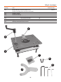
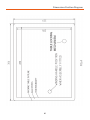
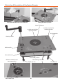
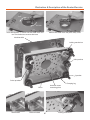
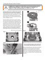
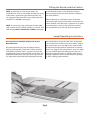
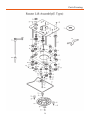
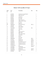
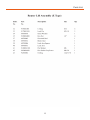
Code 502701 Router Elevator Fast accurate height adjustment from above the table AT&M: 16/03/2015 Index of Contents Page No. Index of Contents 02 Declaration of Conformity 02 What’s included 03-04 Specifications04 Accessories04 Dimensions Position Diagram 05 Illustration & Description of the Router Elevator 06-07 Fitting the Router and the Cutters 08-09-10-11 Setup/Operating Instructions 11 Maintenance12 Parts Drawing 13 Parts List 14-15 Copyright This product has been wholly designed by Axminster Power Tool Centre Ltd who have exclusive use of the design. As such it should not be copied or reproduced. Please dispose of packaging for the product in a responsible manner. It is suitable for recycling. Help to protect the environment, take the packaging to the local recycling centre and place into the appropriate recycling bin. symbols below advise that you follow the correct Warning The safety procedures when using this machine. Fully read manual and safety instructions before use Ear protection should be worn Eye protection should be worn 02 Dust mask should be worn What’s Included Quantity Item 1 off. Router Elevator with Measurement Dial (router mounting plate and table Insert fitted) 1 off. Winding Handle 1 off. Packet containing:6 off. M6 Grub Screws 2 off. M6 Countersunk Bolts 1 off Nippled ‘Y’ wrench (for Table Insert) 4 off. Hex Keys 6mm/4mm/3mm/2.5mm A Model Number 502701 B C D E F E B A C D F E 03 What’s Included Having unpacked your machine and its accessories, please check the contents against the equipment list ”What’s in the box”, if there are any discrepancies, please contact Axminster Tool Centre using the procedures laid down in the catalogue. Please dispose of the packaging responsibly; much of the material is bio-degradable. on top line and prolong its life. Keep this Instruction Manual readily accessible for any others who may also be required to use the machine. Please read through the section entitled Identification and Description of Parts, so that you will be familiar with the terminology we will use in the manual, and so that you can identify the parts quickly and easily. Please read the Instruction Manual prior to using your new tool; there are daily and periodic maintenance recommendations to help you keep your machine Specifications Code 502701 Machine Table Size 306mm x 229mm x 6mm Rise and Fall Platform Size: 275mm x 200mm Router Mounting Plate Circular Universal Type Maximum Rise and Fall 100mm Rise and Fall Linear Movement per turn 2mm Floating Measurement Dial Graduation 0.125mm Centre Hole Diameter (Without insert ring) 92mm Centre Hole Diameter in Insert Ring 38mm Centre Hole in Rise and Fall Platform 75mm ‘Lost’ Cutter Length (from router mounting plate to machine table) 14.5mm Overall Size L x W x H L 306mm x W 229mm x H 165mm Weight 6 kg Accessories Axcaliber Router Collet Extension (1/2” Shank) (Code: 211367) Note: The Assembly requires a through table void of 280mm x 205mm. The recess for the Machine Table is 306mm + 229mm + 6mm + deep. The dimensions and the position are shown on the next page (See Fig A) 04 Dimensions Position Diagram 05 Illustration & Description of the Router Elevator Lock Turn the handle clock-wise to raise the table Locking the table in position 38mm Table insert x2 Grub screw hole for support functions x4 Grub screw hole for levelling function x2 Countersunk hole Winding handle Machine table Drive mechanism Rise and fall platform Reference marker for the measurement dial Measurement dial Table locking mechanism Depth stop nut 06 Threaded rod Illustration & Description of the Router Elevator Lock Un-Lock Insert the Nippled “Y” wrench into the table insert and turn un-clockwise to remove the insert Remove the table insert and place safely aside Machine table Locking mechanism Idler sprocket Sprocket Drive sprocket Clamping lug Universal router mounting plate Chain Table locked Table un-locked 07 Locking mechanism Fitting the Router and the Cutters Introduction The information below is reproduced from the Axminster universal base plate fitting instructions and the hole layout on the router elevator base plate is identical. Hole numbers, screw types and how many required are given for mounting different router models to the router elevator base plate. For advice on models suitable for fitting to the router elevator please call our technical sales team on 0800371822 Please note: Some of the router’s listed in this chart may not be suitable for use with the router elevator. Router Chart Hole Router Model ATLAS COPCO OFSE2000 BOSCHGOF1600,1700ACE POF52, 400,500A,600ACE POF800ACE.GOF900A <2003 GOF1300ACE,900A>2003 GMF1400 CASALS FT750,1000E,2000VCE CMT CMT1E,CMT2E DEWALTDW613,614,615,620,621, DW625EK.629 DRAPER R1900V PT1200V ELUOF97(E),MOF177(E),131,98, MOF77,96(E) MK2,69’ FELISATTIR346EC FESTOOF2000(E) OF1E,900(E),1000(E) FREUDFT1000(E),2000E HITACHIM8(V) M12V,M12SA TR12 MAFELLL050E MAKITA3620,3612BR,3600B 3612(C) RP0910,1110C PERFORMANCECLM1250R<11/03 PRO CLM1250R >11/03,CLM2050R PERLESOF808(E)>1999’,2-808(E) OF9(E) PEUGEOT DEF570E.DF55E RYOBIRE600N,R600N,RE601 ERT1500V R500,502 R150,151,RE120,155K SKIL1835U.1875U1 TRENDT3,T4,T5,T5MK2’,T9,T10,T11 WADKINR500 08 2 Fx3 1 Fx2 3Fx2 4 Gx3 5Gx3 0Ix4 2Fx3 1Fx2 1 Fx2 1Fx2 2 Fx3 1Fx3 1 Fx2 1 Fx2 1 Ex2 7 Ex3 8Bx4 2 Fx3 10 Dx4 11 Dx4 11&12Dx4 8 Bx4 13 Dx2 14Ex2 1Fx2 18 Ax3 1 Fx2 1 Hx2 1Hx2 15 Ex2 13 Dx2 13Dx2 16 Ax4 15Ex2 17 Cx3 1 Hx2 16 Ax4 Fitting the Router and the Cutters Universal Base Plate 176mm 7mm A B M4x10mm M4x12mm 1 C UNF10 x1/2” D M5x16mm E M5x20mm F M6x16mm G M6x30mm 3 2 09 H I M6x12mm M4x6mm Fitting the Router and the Cutters IN ORDER TO FIT SOME OF THE ROUTERS TO THE ELEVATOR AND ACHIEVE UNRESTRICTED MOVEMENT, IT MAY BE NECESSARY TO REMOVE THE HANDLES; PLUNGE THE ROUTER BODY TO DEPTH, ETC., ETC. Lower the table to almost its fullest extent. Using the Allen key provided loosen the bolts and therefore the lugs holding the universal mounting plate (UMP) in position and remove. (See Figs 1 and 2). Remove the sole plate from your router, see illustrations 1 to 2 and secure your router to the UMP via the appropriate holes, see pages 8-9. Insert the requisite tool into the router and tighten securely. 1 Adjust the ‘depth’ of the router to give the slightly more than the required exposure of the tool (to allow for adjustment) and lock the body. Remember that you will loose 14.5mm of the set ‘height’ of the cutter between the lower face of the universal mounting plate and the upper surface of the machine table. Alternatively, current practise would indicate that the router is plunged to maximum depth and all height adjustment is done using the elevator. Refit the mounting plate to the rise and fall platform. (See Fig 3) Sole plate 2 UMP (universal mounting plate) Fig 3 Fig 1 Router/mounting plate mounted in the router elevator Fig 2 Please note: Removing the router handles will prevent them from interfering with the chain. Re-fasten the holding lugs. If the router tool diameter is greater than 75mm, the router/mounting plate combination must be refitted to the rise and fall platform first, and then the tooling mounted into the router. (Hint. You will find this easier with the rise and fall platform at its highest position and the table insert removed). Mounting plate holding down lug 10 Fitting the Router and the Cutters NOTE. If you find that some of your cutters are ‘borderline’ for ‘reach’ or the length of shank remaining in the collet is approaching the minimum limit, may we suggest the purchase of the short collet extension Axminster No. 211367. (See Page 4) to orientate the router so that the power switch is easily accessible when the router elevator is fitted to the work platform. When everything is assembled to your satisfaction. Check the speed setting of the router is correct for the cutter diameter. Give the router a ‘quick burst’ to check that everything is secure. If the ‘quick burst’ check is O.K. proceed to fit your fencing, dust extraction etc NOTE. If you are not using a professional router table with a remote On/Off switching facility, or a Power Tool NVR Switch (similar to Axminster 910065) remember Setup/Operating Instructions Ensure you have identified all the parts of your Router Elevator. the work platform, ensure that the ‘front’ of the table is low in the recess, and the ‘rear’ of the table is high to the work surface. (Low and High in this instance refer to the minimal measurements required to ensure that there is no ‘edge’ for the work piece to ‘snag’ on). When you are satisfied with the levelling process you can, if required, fasten the elevator in position with the two M6 bolts supplied or even two Wood Screws. (perhaps an MDF working platform/table?). Place the Router Elevator into the prepared recess. (See Fig A on page 05). Check that it is flush with the work platform surface. If this is not the case insert the supplied grub screws in the threaded corner holes and level the machine table. (See Fig 4) If, for some reason, it is impossible to level the table absolutely flush with Straight edge Grub screw Fig 4 11 Maintenance The router elevator requires minimum maintenance, but you are advised to observe the following points:1. Keep the elevator clean. Ensure that dust/chips etc., are cleaned away at the end of a work session. 2. Do not allow a build up of dust/chips etc., between the machine table and the rise and fall platform, or under the machine, where it may foul the chain drive. 3. If the winding action becomes ‘lumpy’ check that there is no debris caught in the chain, or compressed onto a sprocket. 4. Check the chain tension. If the chain has become ‘slack’ or loosened, re-tension by adjusting the idler sprocket. Do not over tension, the chain needs to be firm, with a small side to side movement (best checked on a ‘long’ side) it does not need to be rigid. (See Figs 5 and 6) 5. Remember! A chain is a machine as well, give it a light lube. Fig 5 Fig 6 Loosen the idler sprocket bolt, using a 6mm Hex key and adjust the sprocket until the chain is firm idler sprocket 12 Parts Drawing 13 Parts List 14 Parts List 15 The UJK technology brand was launched by us in 2012 with the intention of encompassing a range of carefully selected products that we held in particular high esteem. Many of these products are designed by us and manufactured by one of our most trusted Far Eastern suppliers. The range includes routing, measuring and wood jointing products and has already proven extremely popular. We are continually striving to develop and increase this range of quality innovative products, so watch out for some even greater UJK technology designs and ideas. Please dispose of packaging for the product in a responsible manner. It is suitable for recycling. Help to protect the environment, take the packaging to the local recycling centre and place into the appropriate recycling bin. Only for EU countries Do not dispose of electric tools together with household waste material. In observance of European Directive 2002/96/EC on waste electrical and electronic equipment and its implementation in accordance with national law, electric tools that have reached the end of their life must be collected separately and returned to an environmentally compatible recycling facility. Axminster Tools & Machinery Ltd Weycroft Avenue, Axminster, Devon EX13 5PH axminster.co.uk