1
·
.
=~©®fF>t!:
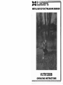
METAL DETECTOR/TREASURE SEEKER
VL~TR1200B
OPERATING INSTRUCTIONS
INSTRUCTIONS VLF.TR 1200-8
INTRODUCTION
IMPORTANT To protect your investment complete both sections of the guarantee at the back of this
instruction manual and return the reply-paid portion to C-Scope. This is particularly important in order
to obtain the free second year parts guarantee. Please retain the packing box. In the event your detector
should ever require service this package will be most suitable for postal protection.
C-Scope detectors are recognised as the finest metal detectors available. They are designed with lasting
quality in mind, high technology input, and above all, value.
'
The only way to realise this value and quality is to carefully study and understand this instructi0'1
booklet. You will then be able to obtain all of the advantages designed into.your detector. It is also
strongly recommended that you experiment with the detector operation indoors in air with test samples,
in order to learn to identify and understand the detector's capabilities and responses. It is best to lay
the detector on a table with the head off the end and pass the test objects across the search head to
best stimulate actual responses.
FEATURES
Before progressing to the controls and the operating procedure it is important to understand the
principles of operation of the 1200-8.
The 1200-8 principle features:
Ground Effect Elimination - Ground Exclusion.
Rejection of selected items - Discrimination.
GROUND EXCLUSION
What is Ground Exclusion?
On some sites mineralisation caused by iron deposits or iron oxides or wet salt sand makes it difficult
to operate a detector successfully. The effects of these minerals is termed 'ground effect'. In practice
the signal of the detector alters if the search head is not kept exactly steady during sweeping and the'
gap between the search head and ground varies the correct tuning level cannot be maintained and
therefore depth penetration is reduced. If the tuning level varies upwards, as on inland sites when the
detector head is inadvertently raised, the signal may also be confused with a target signal.
The 1200-B is programmed to eliminate ground effect i.e. ground exclude.
Inland Sites
The G-mode is the mode in which 'ground exclusion' is achieved. The programmed level of grourjd
exclude of the 12oo-B in the G-mode will overcome most ground effect, even severe mineralisation o"n
inland sites. When operated in the Meter Discriminate mode the 12oo-B will. give ground exclusion in
the audio channel and discrimination in the meter channel both at the same time.
Beaches
On wet salt sand the 1200-8 will eliminate ground effect b',' operating in the D1 or D2 mode, and
varying the discriminate level to suit.
DISCRIMINATION
What is Discrimination?
It is an obvious advantage when metal detecting to get different signals for worthwhile as opposed to
worthless objects anc! therefore be able to discriminate or differentiate between them, and hopefullv
reject the signals given by worthless objects. The 1200-B gives this information in various ways. Basica:IY
a rejected item will cause the signal to fall. The meter needle will drop to the left, and the sound level
will die away. On the other hand, a good target object will cause the signal to rise. The meter needle
will move from the central tuning position to the right, and the sound level will increase in loudness.
When operated in the Meter Discriminate mode the 1200-B's discrimination is restric . .:d to the meter
channel. A rejected item will therefore cause the meter needle to drop to the left. The audio signal in
this mode will be an increase in sound loudness for all targets.
If an object is very close to the search head. conflicting signals will occur. These signals are characterised
by hard swings of the meter from left to right. If you encounter such problems you should raise the
search head a few inches, retune and rescan. You should now receive a clear signal.
These anomaly signals are caused by the object overloading the signal. Normally iron fragments or
wire on the surface cause this phenomenon.
2
CONTROLS
A On/Off Tune Control
. B Sensitivity Control
C Function Control
1) Discriminate Level Control
E Control Box Fasteners
F .ADC Control
G Meter
H Battery Check
I Upper Stem and Handle
J Middle Stem
K Lower Stem
L ADC (Control Box)
M Search Head
N Cable Socket (Head Lead)
ASSEMBLY
Diagram 1.
How to Assemble your 12OO-B for Use.
Your 12oo-B comes to you dismantled for ease of packing. To assemble follow these f8"1 easy steps.
1.
Locate the stems in the special compartment in the packaging.
2.
Loosen the knurled nut on the upper stem and handle (I).
3.
Insert middle stem (J) into upper stem and tighten the knurled nut.
4.
Attach lower stem (K) to the search head (M) with the nut and bolt provided, tightening
the latter finger tight (do not use any tools as you may damage the nut and bolt!
5.
Insert lower stem (K) into middle stem (J) and tighten knurled nut.
6.
rJol" coil the hec"d cable around the whole stem assembly, insert the plug into the head
cable socket (N) ensuring that it is correctly aligned, and twist locking collar. Please
ensure that the search head cable is not coiled around the stem assembly too tightly
especially at the search head end, thus allowing sufficient play, avoiding damage should
the head be moved in relation to the stem.
BATTERIES
Now that you have assembled your 1200-B, all that is required before you use it is the povver supply.
Your 1200-B can be powered by two types of power source:
12 Penlight batteries of HP7 type or
12 Rechargeable Nickel.Cadmium Penlight batteries.
Please Note: It is advisable to use batteries manufactured by a well-known manufacturer, as 80%
of faults occurring with metal detectors can be traced to faulty or badly connected batteries.
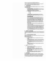
To fit batteries turn control box fasteners (E)
Alii. . . - ...
i
0
anticlockwise through 90 • Lay the top of the
I
..
control box next to the lower half, ensuring
there is no strain on the wires connecting the
two halves. Insert the batteries into the battery
holders supplied. Seat each holder in battery
well and ensure connections are firm and tight.
Replace top half of control box and replace
fasteners.
Battery life will be longer if headphones are used.
CONTROLS AND WHAT THEY DO
"
_
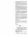
A.
ON/OFF TUNE CONTROL
Diagram 2.
This control turns the detector on and off and sets the tuning level. It must be used in conjunction
'./\lith the ADC Control (F).
To tune thedeteetor tothe optimum level.-turn this control clockwise, whilst at the same time operating
the ADC control, until a faint sound can. be heard and the meter reads within the TUNE position on
the meter scale. Any setting above or below this level of tuning will reduce the sensitivity of the detector.
SENSITIVITY CONTROL
B.
This control will vary the electronic gain of the detector to give a balance between performance and
ease of use. The main purpose of the control is to allow the operator to reduce the sensitivity of the
detector to ground effect when operating in the D modes which do not have the facility to exclude
ground effect on inland sites. It works on the principle that it is better to reduce the ground effect
and keep a consistent tuning level, even if some depth penetration is sacrificed, than to operate at the
highest sensitivity level for its own sake, and find the detector hard to control. A good illustration of
its function is the parallel with a car's headlights. Although full beam !lives lightin!l power, in fO!l the
3
lights give better overall performance when dipped and employing less power.
Reduction of the sensitivity control may also be necessary to reduce instability of the signal when
caused by interference from electrical. radio or other electronic transmissions.
C.
FUNCTION CONTROL
This switch allows the user to choose a mode setting most suited to a particular site. The 1200-8 has
two main modes of operation.
1.
2.
Meter Discrimination Mode: In this mode the 1200-8 offers ground exclusion via the
audio channel whilst simultaneously discriminating via the meter channel. The objects
rejected in this mode are small pieces of iron and silver paper.
Analytical Modes: Tt;lis main mode is divided into three optional modes:
G - 01
G - 02
G 03
In these, modes the detector can be used in either a ground exclude mode (G) or a
discriminate mode (D) 01,02 and 03 which offer increasing levels of discrimination.
Recommended Mode Settings
In general the Meter Discriminate mode is the recommended mode ~,o,tting for most
sites. It is an extremely effective mode of operation, because it is simple. The correct
level of ground exclude is electronically pre-set as is the discriminate level. The level
chosen for ground exclude is designed for a heavily mineralised inland site. The level
chosen for discriminate is the setting where the highest level of discriminate can be
achieved without sacrificing performance. There is therefore no danger of rejecting
anything worthwhile, as sensitivity to small objects. even thin section objects. is at its
highest in this mode.
The Analytical mode, on the other hand. C8fl be used for specialised purposes or when
full manual control is required.
For wet salt sand 01 or D2 mode with the (equired Discrimination level is recommended.
In exceptional circumstances G-D3 could be used to obtain rejection against pull tabs,
but at these high levels of discriminate i.e. those equivalent to 03 Discriminate Levels
5-10, depth penetration will start to suffer on cupro-nickel coins and jewellery. Where.
small iron fragments abound and it is not practical, because A the high incidence of signals.
to operate in the Meter Discriminate mode, the 01 mode offers a useful alternative.
D.
DISCRIMINATE LEVEL CONTROL
This control is the fine tuner for the three discriminate levels 01. 02 and 03.' 01 Discriminate Level 10
is equivalent to 02 Discriminate Level O. This control does not function when in the meter discriminate
mode.
F. & L.
ADC AUTOMATIC DISCRIMINATE CONTROL
I n practice, when you have chosen and set your operational mode. the ADC control is the only control
necessary to operate the 1200-8.
The ADC control has two main functions:
1.
The AbC acts as a memory recall control to automatically recall the 'optimum level
of tuning.
2.
The ADC acts as a function selector. For example. if the function control has been set
at G-D1. to select the G mode the user will press the switch to the 'Ieft and then release
it. To select the D mode. press the ADC switch to the right and then release it.
I n the meter discriminate mode the ADC control only acts as a memory tuning recall
switch.
The switch (Ll is an optional ADC control for use when the detector is used with the
optional hipmount armsaver kit.
G.
METER
1.
2.
3.
4.
H.
The meter acts as a battery check. See (HI.
,
The meter will give a visual indication of the optimum tuning level when the
needle is in the central TUNE position.
When discriminating in a 0 mode or when in the Meter Discriminate mode. the
meter will show a negative response to unwanted items (needle will swing from the
centraJ setting to the Jeft).
When pinpointing a target signal, the fullest deflection of the meter to the right will
indicate that the object is situated under the centre of the search head.
BATTERY CHECK
.I\s a guide to the battery condition a battery check (H) is provided. To check 'battery condition,
switch on the detector by turning the On/Off control knob into the 'on' position, operate the ADC.
then press switch (H). If the needle on the signal intensity meter swings into the bold red sector
of the meter the batteries are in good condition. Should the needle not reach this sector of
4
the rYete, (and remain) the batteries need to be renewed. (If the batteries give a low reading at the
beginning of an outing, it may be that during searching, after some use, the batteries will fall below
the minimum level for correct operating.)
A penlight battery pack with 6 HP7 each with a nominal voltage of 1Y:,v make up the 9 volt pack.
The detector will continue to function until the voltage falls below 6 volts. At this point it will still
function, but the sound stability will deteriorate, and the signal over a target will latch on full reading.
A critical time is when the battery pack is about to fEll below 6 volt. After use the voltage will fall
below the necessary level, but equally after rest the batteries will recuperate and gi\'e sufficient power
for normal operation.
The use of headphones is strongly recommended not only for better performance, but because head
phom s do not drain the batteries as quick Iy as the loudspeaker.
Rechargeable batteries represent a good alternative, with the rising cost of standard batteries. Unlike
standard batteries, rechargeable nicad cells maintain the same voltage throughout their storage and use.
As they become discharged with use the voltage will then drop completely, unlike the gradual decay
of standard batteries. Whilst a standard battery will last, say, 25 hours of use, a rechargeable cycle will
be 8 hours, but recharging will give up to 500 x 8 hour cycles of use. If you detect for four hour
sessions the batteries should not be charged after each session of use. It is more efficient to go as near
as possible to the discharge point before recharging. A full 14 hours should be allowed for recharging.
I. J. & K.
DETECTOR STEMS
These connect by inserting one within the other. A metal knurled nut containing a plastic olive effects
the tightening. It is recommended that the knurled nut is placed over the thinner of the stems of any
two being connected together before sliding this stem into the thicker one. The knurled nut can then
be offered up to the thread on the thicker stem and tightened. This procedure avoids the possibility
of pushing the plastic olive into the stem. If you tighten the knurled nut and the pipes are still not
secure, the plastic olive has become unseated from the knurled nut as described.
M.
SEARCH HEAD
The concentric coi I arrangement of the search head is designed to transmit and receive a magnetic field
and detect the changes that occur when metal is present. Because the receive coil is in the centre and
the transmit coil around the perimeter, the hot-spot or pinpointing area is in the exact centre of the
search head.
.\
C-Scope search heads are fully waterproof and can tht3refore be immersed in rivers,rockpools, etc. up
to the lowest knurled nut. After use, particularly in salt water, it is advisable to wash off the search
head and lower stem in fresh water. It must be remembered that the search head is very sensitive to
temperature changes. It is therefore important to allow the detector to reach the temperature of the
surroundings in which it will be used. For example, if you take the detector from a hot car on a cold
day, the detector will drift until the head has absorbed the temperature chaAge.
OPERATING PROCEDURE
Setting the Tuning Level of the Detector
The fundamental principle of detector operation is that the detector should be tuned to the correct
level. This is the level when the signals are balanced, and is indicated by the detector being neither
silent nor sounding off. In fact, the correct tuning level is the threshold setting when the sound is
just beginning to break through.
For best results, it is important to set this tuning level accurately and to maintain it at all times when
searching.
Follow this procedure:
As a starting point
1.
Set the detector to Function
G -1
Discriminate Level
o
o
Sensitivity
On/Off Tune
o
2.
Switch the detector ON.
3.
Hold ADC switch to the left, and at the same time rotate the TUNE control clockwise
until the sound just begins to break thrclugh, and the meter reads in the central TUNE
position. Release the ADC switch. The detector is now correctly tuned.
The ADC switch has programmed the correct tuning level into the detector's memory, and there
should be no further requirements to operate the ON/OFF TUNE control. If the tuning level alters
simply operate the ADC switch to recall the optimurr tuning level.
OPERATING IN THE METER DISCRIMINATE MOI)E
Follow Sections 1-3 "Setting the Tuning Level of the Detector". To operate in the reco;nmended
mode METER DISCRIMINATE:
4a.
5a.
Hold ADC to the left or right and switch the function control to METER DISC ON
position.
The Sensitivity Control can be adjusted up to +5 as,in the METER DISCRIMiNATE
5
6a.
7a.
8a.
ga.
10a.
mode. However, if ground effect is a problem on the meter channel or interferencE
occurs as previously described (B) you should reduce the Sensitivity Setting.
In the METER DISCRIMINATE mode the DISCRIMINATE LEVEL does·notfunction
In the METER DISCRIMINATE mode the detector operates through two Channels.
The audio channel ground excludes, and the meter channel discriminates. Both these
channels are pre-set so no adjustments are necessary.
Lower the search head to the ground. Ensure that the search head is kept level with
the ground. Ensure that the correct tuning level has been set and then commence
searching. sweeping in rhythmic arcs from one side to another, and advancing about
six inches after each sweep.
Every metal object within range of the detector will give an audio response, and the
user should first concentrate on recognising variations in audio signal level.
Once a target has been recognised the user can then consult the meter response. With
practice the recognition of a signal and its analysis become synchronised and it is
possible to disregard signals caused by iron and continue sweeping.
A signal caused by 'iron will give an audio signal, but the meter will swing left towards the REJECT
end of the meter scale.
The meter channel is not as sensitive as the audio channel and some signals will give a clear audio
response without a noticeable meter indication. The golden rule should always be:
If it is not rejected by a clear negative response the target should be investigated.
However to optimise on the range of the detector and its analytical abilities,
follow this procedure:
(1)
(2)
(3)
(4)
After receiving a target response when sweeping note exact location of target.
Move search head two to three feet away from the object.
Place the search head on the ground and retune the detector by operating
the ADC switch.
Keeping the search head on the ground sl ide the head back over the target object.
This method should increase the meter response because the search head is nearer to the object, the
detector is at its optimum tuning level, and ground effect cannot interfere with the meter channel
because the gap between the search head and the ground is constant, i.e. nil.
The meter channel is set at a level which guarantees that there can be no loss of depth or response to
silver, copper or gold objects, however small or thin in section. Because response to these objects has
been taken as the overriding priority the detector will give a positive response to pull tabs, or even
large pieces of silver paper.
A higher level of discrimination can be obtained by operating in the G-D3 mode. However, operating
at Discriminate levels beyond Mode D2, Discriminate Level 5 may result in depth losses on certain
objects such as cupro-nickel or thin section jewellery.
The Discriminate level of the meter channel which is fixed as previously described is equivalent to
Mode D2 Discriminate Level 5.
OPERATING IN THE ANALYTICAL MODES
To operate in one of the three analytical modes:
G - D1
G - D2
G - 03
,
it is necessary to decide which level of discriminate is requirea4'or' the site you wi:-: :':"J. o.earching. For
instance, or a ploughed field where silver paper and ring pulls are not a problem the user will probably
select G-D1. On another site, say a picnic si~e where silver paper and some ring pulls abound, the user
will probably select G-D2 or even G-D3. Always though, use as little discrimination as the site allows.
Follow steps 1-3 "Setting the Tuning Level of the Detector" and then se!ect the most suitable mode
by following this procedure:
4b.
5b.
6b.
7b.
:C;b.
6
Lower the search head to the ground. Keep at a steady height above the ground and
ensure the Tuning Level is set correctly by operating the ADC switch firmly to the
left or right and then release it.
The principle of the Analytical'Moce operation is to search in the Ground Exclude
Mode (Gl and then analyse any target by switching to the relevant Discriminate
Mode (D).
To select the (G) mode press the ADC switch to the left and then release it.
When a target object has been located, note the location of the signal and take the
search head away from the object at least two to three feet. Select the (D) mode and
ensure the tuning level is at the correct level by pre~sing the ADC switch to the right
and then release it.
Carefully rescan the target object, ensuring that the search head is kept level with the
ground.
9b.
10b.
11b.
To analyse the find: a rejected object will give a swing to the left on the meter and a
decrease in audio response; a worthwhile target will give a swing to the right on the
meter and an increase in audio response.
The Discriminate Level may be fine tuned in each of the three main D modes by
varying the Discriminate level control.
The Sensitivity Level may be varied but 0 is the recommended level in the
Analytical Mode.
OPERATING IN THE DISCRIMINATE MODE
On a wet salt beach it is best to operate in a Discriminate Mode all the time. This is because the salt
water makes the ground conductive. and to ground exclude in these conditions the detector needs
to be set at a point where iron is rejected. This is a useful coincidence because it means that ground
exclusion and discrimination against iron are possible at the same setting on wet salt sand with the
1200-8. The ground exclude setting for beaches is not as exact as that for inland siles and in practice
it is possible to reject silver paper and ground exclude on a beach. D2 or D1 are the recommended
mode settings. The qiscriminate level can also be adjusted to suit the particular conditions.
Follow Steps 1·3 "Setting the Tuning Level of the Detector."
4c.
5c.
6c.
Lower the search head to the ground. Keep it at a steady height above the ground and
p.nsure the tuning level is set correctly by operating the ADC switch to the left or right
and then release it.
To operate in a Discriminate Mode set the Function Control to the relevant D level.
and then press the ADC switch to the right and then release it.
The Sensitivity Level may be varied. On a beach +5 is recommended. If. however. the
detector is being operated in the Discriminate Modes on an inland site. it will be
necessary to balance the Sensitivity Level to reduce the ground effect. I n practice th is
means setting it to the highest level possible. which will of course depend on the degree
of mineralisation. and how capable the operator is at keeping the search head level with
the ground. A sacrifice in Sensitivity Level will drastically reduce the ground effect. but
will not reduce the depth penetration to the sam~ degree. For example, by reducing the
SensitiVity level from +5 to O. ground effect willl:)e reduced by 800%, but depth
penetration will only be reduced by about 20%.
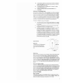
USE IN THE FIELD
~~~
X
Detection Area
TR detectors employ a Total Response search
head which means that the object can be
detected across the full width of the search
head.
\~
Search Are
_.~
_____l
~
r----_____....
Diagram 3. .
Detection Range
Detection ranges will vary depending on the size of the object, the length of time an object has been
buried. and the type of ground the object is buried in. The best ground conditions are dry well
compacted soils then coins can be found at the greatest depths if they have been buried for some
time and the coin has interacted with the salts in the nround, thereby appearing larger to the detector.
The worst conditions for detecting are on loosely compacted or freshly dug ground or when the object
has only recently been buried. In these conditions detection range will be reduced. 90% of all objects
are found within 6" of the surface. Adverse soil conditions can reduce depth of detection by more
than half.
II
Determir,ing the Target Size and Depth
An operator who is familiar with his instrument will be able to do an excellent job of determining
object size,shape and depth before he digs. The technique is learned from careful analysis of the audio
signals coming from the detector. Each time a signal i,; heard, listen for any peculiar characteristics it
may have; determine over how large an area you get a detector signal; and try to 'outline' the object
before you dig. Listen for the sharpness or dullness of the signals and determine the magnitude of
strength of the signal. A coin will have a sharp signal, 3 nail a fuzzy signal.
CARE AND MAINTENANCE
Care of Your Detector
The working life of your detector will be shortened by careless use or neglect of the unit. Think of
your detector as a scientific instrument NOT A TOY. Your detector is designed to withstand rLogged
handling on any terrain, but mis-use or lack of due attention will tell in the end.
7
After using your detector in a hostile environment (salt water, sand etc.) the exterior parts of the
casing should be wiped with a damp cloth, paying particular attention to the head, and carefully
wiped dry. Foreign particles in the control box can be removed by brushing carefUlly (or with
compressed air or vacuum cleaner).
Salt Damage
If you use your detector continually in a salty environment, particularly when the wind is blowing
off the sea, salty air can penetrate the control box.
Corrosion can occur in vital parts of the delicate electronic circuitry.
It is, therefore, recommended that precautions such as covering·the control box with polythene be
,
taken to avoid damage.
The guarantee cannot cover such occurrences and any repairs needed because of salt water or spray
will be charged.
The Use of Solvents
It has been found that some types of solvent used for cleaning circuitry will in fact melt the plastic
covered components.
The life of the controls may be extended by periodic (100 hours of use) application of small quantities
of Iight lubricant to the spindles, threads and knob grub screw ('3 in l' or similar household oil is
suitable). This operation requires the knobs to be removed.
Light packing grease should be smeared on the threads of the locking collar, and at the same time, the
head fixing bolt. Do not store the detector in a damp place.
If the detector is to be stored, remove the batteries as they may leak and corrode the surrounding electronics.
Detector Not Opereting
(A)
(B)
(C)
Check the condition of batteries.
Interchange batteries and ensure connections are correct and secure.
Battery life can vary tremendously between makes, therefore your 'new' batteries may already
be insufficiently powerful to run your detector.
Check the search head cable connector is properly attached to the control box.
Oscillating Signal Accompanied by Slight Meter Fluctuation
(A)
Caused most often by outside equipment such as fluorescent lights, taXis. radios, power lines
and other metal detectors working nearby. Little can be done to alleviate the problem except
tq find a new site.
Intermittent Sound From Speaker
(A)
(B)
This could be due to poor battery connections. Ensure they are tight and the batteries are
securely clipped into place.
Radio transmission from passing taxi or vehicle using radio transmitter equipment.
The Detector Drifts out of Tune
(A)
(B)
IC)
Temperature drift caused by the change ir air t.emperaturewhen a mac:hlne is moved from
a house or a car into the open.
.
The greater the change in temperature the more the drift. and up to 30 tninutes may be .
needed for the electronic circuitry to acclimatize itself.
Sometimes battery drain can causedrift.()f signal. Replace batteries and thjs-should help to
maintain a stable signal.
Before returning a detector for repair to C-$cope ensure you have done the following:
(A)
(B)
IC)
Read instructions thoroughly.
Tried new batteries and checked procedure outlined above.
Speak to local dealer about performance of the detector. especially if you are still
unfamiliar with metal detectors in general.
Return detector with letter giving details of fault.
CODE OF CONDUCT
1.
2.
3.
8
I
,
Do not interfere with archaeological siteS or ancient monuments. Join your local
archaeological society if you are interested in ancierj1t history.
Do not leave a mess. 1t is perfectly simple to extract a coin or other small object buried a
few inches under the ground without digging a great hole. Use a sharpened trowel or knife to
cut a nep.t circle or triangle (do not remove the plug of earth entirely from the ground);
extract the object. replace the soil and grass carefully and even you will have difficulty in
finding the spot again.
Help keep Britain tidy - and help yourself. Bottle tops, silver paper and tir: cans are the last
4.
5.
6.
7.
8.
9.
10.
thing you should throwaway. You could well be digging them up again next year. Do yourself
and the community a favour by taking all the rusty junk you find to the nearest litter bin.
Do not trespass. Ask permission before venturing on to any private land.
Report all unusual historical finds to the local museum and get expert help jf you accidentally
discover a site of archaeological interest.
If you discover any live ammunition or any lethal object such as an unexploded mine, do not
touch it. Mark the site carefully and report the find at once to the local police.
Learn the treasure trove laws and report all finds of gold or silver objects to the Police. If a
coroner's inquest finds that the objects were dl3liberately concealed with the intention of
retrieving them, they become the property of the Crown and therefore Treasure Trove.
But even if the British Museum decides to exercise its right to keep the property, the finder
is granted the full market value.
Respect the Country Code. Do not leave gates open when crossing fields, and do not damage
crops or frighten animals.
Never miss an opportunity to show and explain your detector to anyone who asks about it.
Be friendly: You Juld pick up some useful clues to another site. If you meet another detector
user, introduce yourself. You may learn much about the hobby from each other.
Rem2mber that when you are out with your detector, you are an ambassador for the amateur
metal detecting fraternity. Do not give us a bad name.
A GUIDE TO METAL DETECTING
THE IMPORTANCE OF THE RIGHT APPROACH
You, detector alone is not a guarantee of successful metal detecting. Any detector needs an operator,
and for the best results the operator needs the right approach, attitude and technique. Too many
beginners neglect the importance of pre-planning and research before using their detector in the field,
and patience and technique during the actual search .
.<'., successful search should begin with research sometime before the day of the actual search. The extent
and thoroughness of your research will be one of the major factors in the success of your detecting.
'iou should aim to get as complete an understanding as possible of the local history and geography.
The key to the choice of the site is to think of people, where they congregated over the past few
hundred years. What were their customs and pursuits? Where did they spend money? Where did they
carry money? The answers are not Roman sites, nor are they associated with mystic treasure stories of
crocks of gold. Rather, they are unassuming, undramatic places, like public foothpaths and ancient
rights of way, old houses and so on.
When you have chosen your site, allocate a whole dav from early morning to early evening for the
search. Make sure that you have all equipment you are likely to need. Your detector should be
checked before starting out, and you should always carry a spare set of batteries. You will also need
a strong, sharp trowel. It is also a good idea to have a set of lines and pins so that you can layout
your search area scientificially. Most beginners make the mistake of rushing about hoping to chance
upon a rare find. If for example, there happened to be a valuable ring that was buried 4" deep on the
site you were searching, if you rushed about haphazardly and quickly on the site, the odds would be
very much against your finding it. On the other hand, if you pegged out the area scientifically and
searched slowly and thoroughly, the odds of finding the.ring would be much more In your favour.
Remember, BE PATIENT and WORK SLOWLY. Do not try to cover too large an area. Restrict
yourself to a small area and work through it thoroughly. Make a note of the position and extent of
the area, and then when you return you can start again further on without missing any ground or
covering the same area twice.
It is also important to keep the detector head as CIOSEl to the ground as possible. Ideally. you should
"iron" the ground with the search head of the detector, so that you do not lose any detection range.
Similarly, if you work slowly and carefully you should be able to distinguish the faint signats as well
as the clear-<:ut signals and further increase your find!:.
The technique of getting the best out of your detector is not learnt overnight. You need to get as
much experience as possible so that you can recogniS-3 every kind of signal. Indeed, a good detector
operator can often tell you what is being detected be'fore it is unearthed.
WHERE TO LOOK
It has already been mentioned that the most profitable sites are those where people have congregated,
walked, or lived over the past few hundred years, or e~en longer.
Houses If you live in a Victorian house you might not even have to leave your home for your
metal detecting. Old houses have seen remarkable amounts of money pass over the threshold during
their history. Britain has had its fair share of misers, and it is surprising how many little hoards or
boxes containing savings turn up.
9
One area to concentrate·on is under skirting boards, where coins or rings might have rolled. Doorways
too, may prove rewarding 8$ many money'transactions take place there. Old fireplace and chimeys
should be well scanned with the detector, as these are favourites for finding hoards, etc. The floor
boards should be examined carefully and special attention paid to short lengths which could conceal
caches. It is also surprising how much money is lost in old chairs, so give them a look over. And then,
of course, the garden should be thoroughly examined. The amount of coins lost in old houses cannot
be over-estimated. Most coin shops confirm that many people bring coins in for valuation that they
have found 8c.:ident811v in their houses. A deliberate search in a house of the right age can hardly
fail to be rewarding.
Rivers The best parts of rivers to concentrate on are (1) public footpaths along r~r banks. (2) Bends
of the river where erosion has been taking place. (3) Bends in the river where coins are likely to be
deposited against a particular bank by the action of the current. (4) Areas downstream of old drainage
pipes or upstream of projections such as wooded piers, or other obstructions. (5) Old fords or bridges.
(6) Areas exposed at low tide where eddy action has been taking place.
Tidal rivers are partic;ularly interesting, as once you have found a good site or spot where coins have
collected due to the currents, you can search the area well one day and still return at a later date for
more rewarding finds. Rivers tend to sort out their load and distribute it according to weight along
the bank in places like those itemised above,
Beacluls Beaches are, without a doubt, the favourite haunt of the average British metal detective.
At one time or'another, almost everybody has made the journey to the coast. The beaches are the
only place where people undress publicly; anyone who has attempted to change into a bathing costume
discreetly and then store their coins on the open sand knows the chances of losing not only coins,
but jewellery and wristwatches, too,
Once an object has been mislaid on the beach, it is maddeningly difficult to find it again.
There is also a high incidence of wrecks along our coasts, the contents of which are deposited at
intervals on our beaches.
These factors contribute to make our beaches probably the richest site for the amateur metal
detective. The best times to explore beaches are after heavy storms when the sand has been thoroughly
stirred up and shifted. A good place to concentrate on is along or just below the tide marks, which
are easily identified by the lines of debris that are left. Under piers or alongside breakwaters also
usually pay dividends.
Other good sites are:- Fairgrounds, Children's Playgrounds, Tobbogan runs and Demolition Sites.
METAL DETECTING AND THE LAW
RIGHTS OF THE FINDER
The rights of the finder fall into two distinct classes. The first relates to objects that have recently
been lost, and the second to items of gold or silver which are subject, or might be subject, to the laws
of the Treasure Trove.
In the first place, where the object has been recently lost and found and is valuable, it should be
handed to the Police as soon after it has been found as possible. The Police will then attempt to locate
the owner. If they succeed in locating the owner, he has the legal right to the object and is not legally
boUnd to reward the finder. That is a matter for the owner's conscience.
In the event of the Police failing to locate the owner they will probably return the object to the
finder. If, however, the owner makes a claim for the object at a later date, the finder must return the
item to the owner.
If the owner is not located the finder has the best rights to ownership, provided that the object was
not found on private property, in which case the owner of the land often has a better right than the
finder. The solution here, of course; is10 obtain permission beforehand and to come to some agree·
ment with the landowner with regard to the division of any finds.
If on the other hand, the find of gold or silver can be proved to have been deliberately concealed,
with a view to recovery at a later date, the find comes under the laws of the Treasure Trove. If the
objects cannot be proved to have been deliberately concealed, the find cannot be declared Treasure
Trove. Usually this point centres around the quantity of coins in a hoard, or whether the find is in a
container. Obviously, if there are a hundred or so coins in a pot, they were almost certainly deliberately
concealed. If, however, there are only one or two coins, it is more likely that they were lost accidentally.
If the objects are declared Treasure Trove, the finder has no need to worry, for he is rewarded with a
cash settlement to the full market value of the find.
When the objects are not declared Treasure Trove, the owner of the land on which the find was
made uSlJally has a better claim to ownership than the finder.
In Scotland a/l newly discovered ancient objects of all metals. whether deliberately concealed or not
are S1Jbject to the same procedure as Treasure Trow finds in England.
10