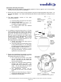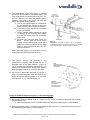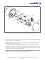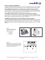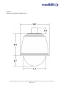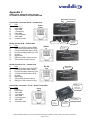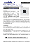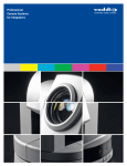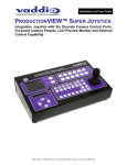
1
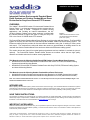
Installation and User Guide Camera and Electronic Products for Integrators DOMEVIEW™ Integrated Outdoor Environmental Pendant Mount Dome Systems and Outdoor Pendant Mount Dome Enclosures for Sony® and Canon® PTZ Cameras OVERVIEW: The Vaddio™ DomeVIEW Outdoor, Environmental Pendant Mount Domes (Figure 1) are integrated camera mounting systems that are attractive and easy to install. Designed for outdoor security applications, and including an internal heater/blower, the 8.2” (20.8cm) Outdoor Pendant mount dome enclosure is outfitted with the internal brackets to support the option of using the Sony EVID70 or the Canon VC-C50iR robotic PTZ cameras. Figure 1: Outdoor Pendant Mount Dome shown with Smoke Tinted Dome standard (Clear is an option) The DomeVIEW Outdoor Pendant Mount Dome Package is sold complete with the Camera. The DomeVIEW system for the Sony EVI-D70 and VC-C50iR features the standard Vaddio EZCamera Cabling System. The EZCamera cabling solution provides for fast and efficient installations using Cat. 5 cabling for video, power and control. The enclosures are also sold without the camera to accommodate an existing camera to be used with the Outdoor Pendant Mount Dome enclosure without the EZCamera cabling system. The outdoor domes are formed from optical grade polycarbonate and are available in smoked tint (clear is optional). The DomeVIEW Outdoor Pendant Mount Domes are excellent values that are high quality, attractive and durable solutions for outdoor security applications. This Manual covers the following Vaddio DomeVIEW Outdoor Pendant Mount Dome Systems: 999-9200-050 DomeVIEW 50iR Outdoor Pendant Dome with Canon VC-C50iR, EZCamera Cabling System and Internal Mounting Bracket 999-9200-070 DomeVIEW 70 Outdoor Pendant Dome with Sony EVI-D70, EZCamera Cabling System and Internal Mounting Bracket This Manual covers the following Outdoor Pendant Mount Dome Enclosures: 998-9200-050 Outdoor Pendant with Internal Mounting Bracket for VC-C50iR (Camera Not Included) 998-9200-070 Outdoor Pendant with Internal Mounting Bracket for EVI-D70 (Camera Not Included) Note: The Outdoor Pendant Mount Domes mount to a 1-1/2” NPT Pipe, which are not part of the DomeVIEW packages or the Outdoor Pendant Mount Dome enclosures. INTENDED USE: Before operating the DomeVIEW system, please read the entire manual thoroughly. The DomeVIEW Outdoor Pendant Mount systems were designed, built and tested for use Outdoors (or indoors) and with the provided power supply. The use of a power supply other than the one provided or has not been tested and could damage the electronics and/or create a potentially unsafe operating condition. SAVE THESE INSTRUCTIONS: The information contained in this manual will help you install and operate your Vaddio DomeVIEW. If these instructions are misplaced, Vaddio keeps copies of Specifications, Installation and User Guides and most pertinent product drawings for the Vaddio product line on the website. These documents can be downloaded from www.vaddio.com free of charge. IMPORTANT SAFEGUARDS: Read and understand all instructions before using. Do not operate the system if it has been dropped or damaged. In this case, a Vaddio technician must examine the product before operating. To reduce the risk of electric shock, do not immerse in water or other liquids and avoid extremely humid conditions. ⓒ2009 Vaddio - DomeVIEW Systems - All Rights Reserved. Reproduction in whole or in part without written permission is prohibited. Specifications and pricing are subject to change without notice. Vaddio, DomeVIEW, EZCamera, Quick-Connect, WallVIEW, CeilingVIEW, EZCable and PowerRite are trademarks of Vaddio, Inc. All other trademarks are property of their respective owners. Document 341-445 Rev C. Use only the power supply (or power supplies) provided with the DomeVIEW systems. Use of any unauthorized power supply will void any and all warranties. Do not use “pass-thru” RJ-45 connectors during installation. standard RJ-45 connectors and test all terminated cables. Use only UNPACKAGING – SYSTEM COMPONENT LISTS Carefully remove all parts from the packaging. Unpack and identify the following parts for each product: 999-9200-050 DomeVIEW 50iR Outdoor Pendant Mount Dome System includes: QTY Description 1 1 3 1 2 2 2 1 1 1 1 1 1 1 1 1 Canon VC-C50iR PTZ camera Canon IR remote control Camera bracket for Canon VC-C50iR PTZ camera 2” x .375 (50.8mm x 9.525mm) ¼”M to 8-32F Hex shaped stand-offs 6.25” x 5.25” (15.87cm x 13.34cm) Camera mounting stage 8-32 x .5” Flat head screws (flush mount) 8-32 x .5” pan head screws #8 Lock washers for pan head screws Outdoor Pendant Mount Dome Enclosure Outdoor Pendant Housing Assembly (white outer shell, black inner shell, safety tethers) Heater/blower fan assembly, mounting platform secured with three 10-32 x .5” flat head screws 8.2” (20.8cm) Smoke tinted dome bubble with four (4) attached stainless steel mounting screws 1-1/2” NPT Locknut Foam dust plug for 1-1/2” NPT pipe fitting Tube of pipe sealer and proprietary Allen wrench (do not lose this wrench) EZCamera Cabling Components 50 EZCamera Shoe (998-4411-001) Quick-Connect (998-1105-001) PowerRite Power Supply (451-2750-018) and separate 24 VAC Power supply for the Heater/Blower 999-9200-070 DomeVIEW 70 Outdoor Pendant Mount Dome System includes: QTY Description 1 1 3 1 2 1 1 2 2 1 1 1 1 1 1 1 1 Sony EVI-D70C/W PTZ camera (platinum white) Vaddio IR Remote Commander (for Sony cameras) Camera bracket for Sony EVI-D70 PTZ camera 1.125” x .375 (28.58mm x 9.525mm) ¼”M to 8-32F Hex shaped stand-offs 6.25” x 5.25” (15.87cm x 13.34cm) Camera mounting stage 8-32 x .5” Flat head screws (flush mount) 6.25” x 5.25” (15.87cm x 13.34cm) Camera mounting plate ¼”-20 x ½” Mounting screw (to attach camera to mounting plate) 8-32 x .5” pan head screws #8 Lock washers for pan head screws Outdoor Pendant Mount Dome Enclosure Outdoor Pendant Housing Assembly (white outer shell, black inner shell, safety tethers) Heater/blower fan assembly, mounting platform secured with three 10-32 x .5” flat head screws 8.2” (20.8cm) Smoke tinted dome bubble with four (4) attached stainless steel mounting screws 1-1/2” NPT Locknut Foam dust plug for 1-1/2” NPT pipe fitting Tube of pipe sealer and proprietary Allen wrench (do not lose this wrench) Vaddio EZCamera Cabling Components EZCamera Cabling Shoe (998-2211-004) 1 PowerRite Power Supply (451-2750-018) and separate 24 VAC Power supply for the Heater/Blower Quick-Connect (998-1105-001) Vaddio DomeVIEW Outdoor, Environment Pendant Mount Dome Installation and User Guide - Document 341-445 Rev C Page 2 of 14 Outdoor Pendant Mount Dome Enclosures Only (Cameras Not Included) The Outdoor Pendant Mount Dome Enclosures are for use with existing or standard Sony EVI-D70 and Canon VC-C50iR. The Dome enclosures can also be used with the Vaddio Standard EZCamera Cable system for the EVI-D70 or the VC-C50i analog PTZ cameras. The dome enclosures without cameras are listed below: 998-9200-050 Outdoor Pendant Mount Dome Enclosure includes: QTY 3 1 2 2 2 1 1 1 1 1 1 1 Description Camera bracket for Canon VC-C50iR PTZ camera 2” x .375 (50.8mm x 9.525mm) ¼”M to 8-32F Hex shaped stand-offs 6.25” x 5.25” (15.87cm x 13.34cm) Camera mounting stage 8-32 x .5” Flat head screws (flush mount) 8-32 x .5” pan head screws #8 Lock washers for pan head screws Outdoor Pendant Mount Dome Enclosure Outdoor Pendant Housing Assembly (white outer shell, black inner shell, safety tethers) Heater/blower fan assembly, mounting platform secured with three 10-32 x .5” flat head screws 8.2” (20.8cm) Smoke tinted dome bubble with four (4) attached stainless steel mounting screws 1-1/2” NPT Locknut Foam dust plug for 1-1/2” NPT pipe fitting Tube of pipe sealer and proprietary Allen wrench (do not lose this wrench) 24 VAC Power supply for the Heater/Blower 998-9200-070 Outdoor Pendant Mount Dome Enclosure includes: QTY 3 1 2 1 1 2 1 1 1 1 1 1 1 1 Description Camera bracket for Sony EVI-D70 PTZ camera 1.125” x .375 (28.58mm x 9.525mm) ¼”M to 8-32F Hex shaped stand-offs 6.25” x 5.25” (15.87cm x 13.34cm) Camera mounting stage 8-32 x .5” Flat head screws (flush mount) 6.25” x 5.25” (15.87cm x 13.34cm) Camera mounting plate ¼”-20 x ½” Mounting screw (to attach camera to mounting plate) 8-32 x .5” pan head screws #8 Lock washers for pan head screws Outdoor Pendant Mount Dome Enclosure Outdoor Pendant Housing Assembly (white outer shell, black inner shell, safety tethers) Heater/blower fan assembly, mounting platform secured with three 10-32 x .5” flat head screws 8.2” (20.8cm) Smoke tinted dome bubble with four (4) attached stainless steel mounting screws 1-1/2” NPT Locknut Foam dust plug for 1-1/2” NPT pipe fitting Tube of pipe sealer and proprietary Allen wrench (do not lose this wrench) 24 VAC Power supply for the Heater/Blower INSTALLATION INSTRUCTIONS DomeVIEW System Packages with Dome, Camera and Internal Mounting Bracket 999-9200-050 DomeVIEW 50iR Outdoor Pendant Mount Dome System 999-9200-070 DomeVIEW 70 Outdoor Pendant Mount Dome System Outdoor Pendant Mount Dome Enclosures 998-9200-050 for the Canon VC-C50iR PTZ Camera 998-9200-070 for the Sony EVI-D70 PTZ Camera For PAL camera part numbers, the last digit is changed to “1” (i.e. 999-9200-071 is a DomeVIEW 70 PAL camera). The instructions are for both PAL and NTSC. Before Starting the Installation For cabling requirements, see the Cabling Requirements section. All installation work must conform to local building codes and should be performed by qualified personnel. Vaddio DomeVIEW Outdoor, Environment Pendant Mount Dome Installation and User Guide - Document 341-445 Rev C Page 3 of 14 Step-by-Step Assembly Instructions: 1) Unpack and verify the contents of the packaging against the lists on pages 2 and 3 of this manual. Carefully remove all parts from the packaging. 2) Remove the dome from the dome housing assembly using the provided proprietary Allen wrench. DO NOT LOSE THIS WRENCH. Use caution when handing the dome to avoid scratching or scuffing the dome bubble. 3) The dome assembly components (Figure2): consists of four major Figure 2: Major Components of the Dome Housing Assembly A. Foam Dust Plug to lock dust out of the dome B. Dome housing assembly C. Mounting Plate with heater/blower premounted on the plate (single fan) D. 8.2” Smoke tinted dome with stainless screws attached 4) It is easiest to mount the dome on the 1-1/2” pipe mount and then install the contents of the dome to avoid cabling problems as the dome is spun onto the pipe mount. The dome can be mounted to a 1-1/2” NPT pipe extension attached to the Vaddio Ceiling Pendant Mount (part # 998-9300-002) or Curved Wall Mount (part # 998-9300-000). These mounts are sold separately. To install the dome to a 1-1/2” NPT Pipe Extension or Wall Mount: A. Thread 1-1/2” lock nut onto pipe mount to the top of the threads. B. Generously apply pipe thread sealer (Figure 3) and install the dome on 1-1/2” NPT pipe by rotating counter-clock wise until threads are fully engaged – at least 5 full turns! C. Additional sealer will be applied in a later step (keep tube handy). The lock nut will be tightened in a later step as well. 5) Remove the Heater/blower fan assembly, mounting platform secured with three Philips head 10-32 x .5” flat head screws as shown in Figure 4. A. First, loosen the two screws on the plate that are key-holed, do not remove the screws. Then fully remove the third screw from the mounting plate. B. Slide the two loosened screws through the keyholes and remove the plate. The mounting plate will be attached to a safety tether. Let the plate hang fro the tether while terminating the heater/blower. C. The heater/blower circuitry will be accessible on the back of this mounting plate. D. Remove the foam dust plug (A –Figure 2) and pull the cabling through into the dome. E. Reinstall the foam dust plug. 1.5” NPT Mount Thread on Lock Nut to top 1-1/2” NPT Pipe Adapter Figure 3 Apply pipe thread sealer to lock out moisture Note: Only one (1) fan will be mounted to this plate Figure 4: Remove the heater/blower mounting platform Vaddio DomeVIEW Outdoor, Environment Pendant Mount Dome Installation and User Guide - Document 341-445 Rev C Page 4 of 14 6) The heater/blower circuit card (Figure 5) receives power from the included 24 VAC power supply. This power supply powers the fans and heater strip only. The 24 VAC output is not used with Vaddio camera systems. The video in and out is not used with Vaddio EZCamera cabling systems. A. The 24 VAC power supply is connected to the AC terminals (24 VAC IN) on the circuit board to power both the heater and the fan. B. Connect the heater strip and fan connectors on the circuit board. C. Pull the camera cabling through the center or backside of the mounting plate making sure that the cabling does not contact the heater strip. D. Re-install the mounting plate inside the dome. Tighten down the three screws making sure the safety tether and all other cables are tucked up behind the mounting plate to avoid interference with the PTZ camera movement. Figure 5: Heater/blower circuit with connections, Use 2-cond 18AWG unshielded cable and locate power supply within 100’ (30.48m of the dome enclosure). The 24VAC OUT is not used. NOTE: the Power supply for the heater/blower must be located within 100’ (30.48m) of the dome enclosure. 7) The camera brackets are attached to the heater/blower mounting plate through two (2) ¼” threaded holes on the plate labeled F (Figure 6). For all mounts the hex shaped stand-offs are ¼”Male to 8-32-Female with the length of the stand-off determining the height of the camera in the dome. Note: Only one (1) fan will be mounted to this plate 8) See Figure 7, thread the stand-offs (7) into the Fholes in the mounting plate inside the dome (8) and attach the camera mounting stage (6) to the standoffs with the 8-32 x .5” flat head screws (5). Front Figure 6: Two (2) ¼”-Male to 8-32 Female standoffs mount to holes marked “F” Canon VC-C50iR Camera Only (Figure 7 on the following page) 9) Attach the EZCamera Cabling Shoe (4 - Figure 7) to the Canon VC-C50iR (DomeVIEW 50iR Outdoor Pendant Dome only). A. When mounting the Canon VC-C50iR without the EZCamera Cabling System – skip this step. 10) Attach the camera (3) to the camera mounting stage (6) with two 8-32 x .5” pan head screws (2) and two #8 lock washers (see Figure 5). Skip to Step 15. Vaddio DomeVIEW Outdoor, Environment Pendant Mount Dome Installation and User Guide - Document 341-445 Rev C Page 5 of 14 Back 7 5 4 8 1 6 3 2 Figure 7: Exploded view of DomeVIEW Outdoor, Environmental Pendant Dome for Canon VC-C50iR PTZ Camera Sony EVI-D70 Camera Only (Figure 8 on the following page) 11) Image Flip Switch, IR Select Switch and other Mode switches (set switches prior to powering up camera) A. Set the Image Flip dipswitch on the back of the EVI-D70 camera to the ON position. The camera will be inverted in the dome enclosure and the image needs to be flipped. B. When using the IR Remote control in an environment with multiple cameras, set the IR Select Switch frequency setting to 1, 2 or 3 to avoid having the IR remote control more than one camera at a time. C. Check the full-length manual for the EVI-D70 camera for other mode switch settings. manual is available on the Vaddio website (www.vaddio.com). The 12) Attach the EZCamera Cabling Shoe, (4 - Figure 8), to the Sony EVI-D70 camera. A. When mounting a Sony EVI-D70 without the EZCamera Cable System - skip this step. 13) Attach the Camera Base Plate (9) to the camera (3) with the provided ¼”-20 x .5” screw (10). 14) Attach the camera (3) and camera base plate (9) to the camera mounting stage (6) with four 8-32 x .5” pan head screws (2) and four #8 lock washers (see Figure 8). Go to Step 15. Vaddio DomeVIEW Outdoor, Environment Pendant Mount Dome Installation and User Guide - Document 341-445 Rev C Page 6 of 14 7 5 2 4 8 1 6 10 9 3 Figure 8: Exploded view of DomeVIEW Outdoor, Environmental Pendant Dome for Sony EVI-D70 PTZ Camera 15) Once the camera is installed in the dome, terminate the camera pull the cable slack back through the pendant extension pipe or curved wall mount. 16) Loosen the dome on the 1-1/2” NPT pipe mount (no more than 1 full turn) and position the dome for preferred viewing angle of the camera. 17) Apply a generous bead of sealer around the top of the dome’s 1-1/2” pipe adapter and pipe threads. 18) Thread down the locking nut to engage the housing and tighten down the 1-1/2” NPT lock nut. Apply another bead of sealer to the top of the lock nut; wipe off the excess working the sealer into the gap between the top of the lock nut and 1-1/2” pipe threads. 19) Replace the dome on the dome housing assembly using the provided proprietary Allen wrench and tighten the dome firmly to lock out moisture from below. DO NOT LOSE THIS WRENCH (please). Use caution when handing the dome to avoid scratching or scuffing the dome bubble. Vaddio DomeVIEW Outdoor, Environment Pendant Mount Dome Installation and User Guide - Document 341-445 Rev C Page 7 of 14 EZCamera SYSTEM COMPONENTS The DomeVIEW Systems are built around either the Sony EVI-D70 (999-9000-070) or the Canon VC-C50iR (999-9000-050) and are shipped with the standard Quick-Connect, PowerRite and EZCamera Cabling Shoe. DomeVIEW 50iR Cabling Distances with Standard and Optional Power Supplies The DomeVIEW 50iR can transmit video up to 185 feet using the supplied 18 VDC PowerRite power supply, and from 185 feet to 275 feet using the optional 24 VDC PowerRite power supply (part# 451-2000-024). This EZ Camera Cabling system provides both S-video and composite video. DomeVIEW 70 Cabling Distances with Standard and Optional Power Supplies The DomeVIEW 70 can transmit video up to 200 feet using the supplied 18 VDC PowerRite power supply, and from 200 feet to 300 feet using the optional 24 VDC PowerRite power supply (part# 451-2000-024). This EZ Camera Cabling system provides both S-video and composite video. The EZCamera Cable Shoe for the Sony EVI-D70 and Canon VC-C50iR The EZCamera Cable Shoe attaches to the back of the Canon VC-C50iR camera and changes the native power, video and control connectors to RJ-45s for use with Cat. 5 cabling. The Shoe has a voltage regulator and transformers (baluns) to optimize the video signal for use over Cat. 5 cable. The RS-232C control cabling uses 5-wires to provide for bi-directional control signaling and daisy chain control of multiple cameras. Figure 9: The Canon VC-C50iR and Sony EVID70 are shown with the EZCamera Cabling Shoes attached. The RJ-45 connectors are: 1) Power/Video 2) RS-232 IN 3) RS-232 OUT Figure 10: EZCamera Cable Shoe for the DomeVIEW 70 shows RJ45 connections for Power/Video, RS-232 IN and RS-232 OUT on the top of the Shoe (upper image). The back of the Shoe (lower image) shows the connector labeling. See Appendix A for pin-out information. POWER VIDEO RS-232 IN RS-232 OUT Vaddio DomeVIEW Outdoor, Environment Pendant Mount Dome Installation and User Guide - Document 341-445 Rev C Page 8 of 14 Figure 11: Basic wiring diagram for cabling the DomeVIEW system For cabling distances using the standard and optional power supplies for the DomeVIEW 50iR and 70, see the previous page for additional information. 1-1/2” NPT Pipe (Not supplied) DomeVIEW Outdoor Pendant RS-232 OUT to next camera for daisy chain control RS-232 on Cat. 5e 24 VAC Power Supply for heater/blower, 2-Cond. 18 AWG unshielded cable – 100’ (30.48m) Max distance CAMERA CONTROL For the DomeVIEW 50iR Outdoor Pendant Mount Dome and DomeVIEW 70 PTZ Outdoor Pendant Mount Dome Systems, the RS-232 control programming information is in the technical manuals for the Sony EVID70 and Canon VC-C50iR PTZ which can be found on the Vaddio website (www.vaddio.com) under the TechNotes tab and under the PTZ Camera product grouping. Control system manufacturers’ also have programs readily available for these cameras to be used with their control systems (i.e. Crestron® and AMX®). Please contact those companies for the demo programs and for debugging of the programs that they provide. Both the DomeVIEW 50iR Outdoor Pendant and the DomeVIEW 70 Outdoor Pendant are shipped with IR remote controllers for camera control. The camera base with the IR window is recessed inside the dome enclosure and the acceptance angle of the IR control signaling is affected. The angle of acceptance for the IR remote control is narrower and more directional. Please take this into account when controlling the cameras with an IR remote. For the DomeVIEW 50 IP Outdoor Pendant Mount Dome System, the Canon software provided with the system controls the camera. The Canon VB-C50iR camera has a network server built-in and produces a Motion-JPEG output. The software included is a single camera license. Additional Canon software is available to monitor either 16 cameras (VK-16 software) or 64 cameras (VK-64) simultaneously. This software is also available from Vaddio. Please see the June 7th 2006 Price List for details. Vaddio DomeVIEW Outdoor, Environment Pendant Mount Dome Installation and User Guide - Document 341-445 Rev C Page 9 of 14 CABLING REQUIREMENTS For the DomeVIEW 70 Outdoor Pendant Dome and DomeVIEW 50iR Outdoor Pendant Dome that use the EZCamera Cabling system, the cabling requirements are as follows: One (1) - Cat. 5 Cable for Power/Video One (1) - Cat. 5 Cable for RS-232 control input One (1) - Cat 5 Cable for RS-232 control output for daisy chaining One (1) - Pair unshielded cable (16AWG or 18AWG) for 24 VAC power supply (100’ / 30.48m Max) (See system drawings on pages 13) For the Outdoor Pendant Mount Dome Enclosures that do not use the EZCamera Cabling system, the native connections on the cameras and original power supply must be used. Custom cables for camera power (12 VDC), heater/blower power (24 VAC), video (S-video or composite video) and control signaling must be fabricated. Note: The RS-232 requires at least 5 wires – preferably paired for TXD and RXD as well as DTR/DSR for Sony control daisy chain and CTS/RTS for Canon control daisy chain. The native control connections of the Sony EVI-D70 uses the 8-pin mini-din female connector for RS-232 in and RS-232 out, and the Canon uses a proprietary 20-pin connector and also has an adapter available to convert the 20-pins into 8-pin mini-din although it is pin differently than the Sony 8-pin mini-din. Please see power supply cable extension disclaimer above. GENERAL SPECIFICATIONS Mechanical Enclosure: Dome: Hardware: Weight: Dual Shell Design; UV Resistant ABS Plastic Outer shell .118” Cell-cast Acrylic Heavy-gauge steel and Aluminum construction 5.26 lbs with heater/blower - camera not included Electrical Input Voltage: Power Requirements Power Supply: Blower: Heater: Operating Range: 24 VAC +/- 10% 1.8 amps (1 heater, 1 blower) - camera not included Power Supply Included, Primary 120VA 60Hz, Secondary 24VAC, 50VA Two (2) 24.8 CFM @ .006 watts, Continuous operation at .16 amps One (1) 40-watt heater With Heater Blower Kit -20°F to 120°F (33°F to 100°F without) Certifications Designed to meet NEMA-4 guidelines and Independently certified to IP66 requirements with proper installation Optional Accessories: 998-9300-000 Curved Wall Mount 998-9300-001 Curved Wall Mount and Pole Mount Kit 998-9300-002 Ceiling Pendant Mount 451-2000-024 PowerRite 24 VDC power supply Note: see page 8 for cabling distance using standard and optional power supplies Vaddio DomeVIEW Outdoor, Environment Pendant Mount Dome Installation and User Guide - Document 341-445 Rev C Page 10 of 14 Figure 12: Outdoor Environment Dome Enclosure Dimensions Dimensions in inches, reference conversion 1” = 2.54cm Vaddio DomeVIEW Outdoor, Environment Pendant Mount Dome Installation and User Guide - Document 341-445 Rev C Page 11 of 14 WARRANTY INFORMATION Hardware* Warranty - One year limited warranty on all parts. Vaddio warrants this product against defects in materials and workmanship for a period of one year from the day of purchase if Vaddio receives notice of such defects during the warranty. They will, at its option, repair or replace products that prove to be defective. See Warranty and RMA Policy documentation on the Vaddio website www.vaddio.com. Exclusions - The above warranty shall not apply to defects resulting from: improper or inadequate maintenance by the customer, customers applied software or interfacing, unauthorized modifications or misuse, operation outside the normal environmental specifications for the product, use of the incorrect power supply, or improper site operation and maintenance. Vaddio Customer service – Vaddio will test, repair, or replace the product or products without charge if the unit is under warranty. If the product is out of warranty, Vaddio will test then repair the product or products. The cost of parts and labor charge will be estimated by a technician and confirmed by the customer prior to repair. All components must be returned for testing as a complete unit. Vaddio will not accept responsibility for shipment after it has left the premises. Vaddio Technical support - Vaddio technicians will determine and discuss with the customer the criteria for repair costs and/or replacement. Vaddio Technical Support can be contacted through one of the following resources: e-mail support at [email protected] or online at www.vaddio.com. Return Material Authorization (RMA) number - Before returning a product for repair or replacement request an RMA from Vaddio’s technical support. Provide a technician with a return phone number, e-mail address, shipping address, and product serial numbers. Describe the reason for repairs or returns as well as the date of purchase. Include your assigned RMA number in all correspondence with Vaddio. Write your assigned RMA number on the outside of the box when returning the product. Voided warranty – The warranty does not apply if the original serial number has been removed or if the product has been disassembled or damaged through misuse, accident, modifications, or unauthorized repair. Shipping and handling - Vaddio will not pay for inbound shipping transportation or insurance charges or accept any responsibility for laws and ordinances from inbound transit. Vaddio will pay for outbound shipping, transportation, and insurance charges all items under warranty but will not assume responsibility for loss and/or damage by the outbound freight carrier. If the return shipment appears damaged, retain the original boxes and packing material for inspection by the carrier. Contact your carrier immediately. Products not under warranty - Payment arrangements are required before outbound shipment for all out of warranty products. *Vaddio manufactures its hardware products from parts and components that are new or equivalent to new in accordance with industry standard practices. Vaddio DomeVIEW Outdoor, Environment Pendant Mount Dome Installation and User Guide - Document 341-445 Rev C Page 12 of 14 Appendix 1: Vaddio Power, Video and Control Pin-outs For Vaddio DomeVIEW 70 and DomeVIEW 50iR Power/Video Connector Power/Video Connection RJ-45 – Camera Shoe # Pins Power 1) Power (+) Video 2) Power GND 3) Video GND 4) Y (luminance) 5) Video GND 12345678 6) C (Chrominance) 7) Video GND 8) Composite Video Vaddio Camera Shoe Back View Top View RS-232 OUT RS-232 Connector IN – Camera Shoe # Pins 1) DTR (Sony® Daisy chain to DSR) 2) DSR (Sony Daisy chain from DTR) 3) CTS (Canon® Daisy chain to RTS) 4) RTS (Canon Daisy chain from CTS) 5) Unused 6) Digital GND 7) RXD (from TXD of control source) 8) TXD (to RXD of control source) RS-232 Connector Out – Camera Shoe # Pins 1) DSR (Sony Daisy chain from DTR) 2) DTR (Sony Daisy chain to DSR) 3) RTS (Canon Daisy chain from CTS) 4) CTS (Canon Daisy chain to RTS) 5) Unused 6) Digital GND 7) TXD (to RXD of control source) 8) RXD (from TXD of control source) RS-232 In RS-232 IN Power/Video Connector RS-232 IN 12345678 Vaddio Camera Shoe Back View RS-232 Out RS-232 OUT 12345678 Power/Video Connection – RJ-45 – Quick-Connect Box # Pins Power 1) Power + Video 2) Power GND 3) Video GND 4) Y (luminance) 5) Video GND 6) C (Chrominance) 12345678 7) Video GND 8) Composite Video Vaddio Camera Shoe Back View RJ-45 Power/Video Connector to Camera Shoe Top S-Video From Camera Power View Supply To Camera Shoe Composite Video From Camera Vaddio DomeVIEW Outdoor, Environment Pendant Mount Dome Installation and User Guide - Document 341-445 Rev C Page 13 of 14 4800 Quebec Avenue North ▪ Minneapolis, MN 55428 Toll Free: 800-787-8078 ▪ Phone: 763-537-3601 ▪ FAX: 763-537-2852 www.vaddio.com ©2009 Vaddio, All Rights Reserved. Reproduction in whole or in part without written permission is prohibited. Specifications and pricing are subject to change without notice. Vaddio, DomeVIEW, EZCamera, Quick-Connect, WallVIEW, CeilingVIEW, EZCable and PowerRite are trademarks of Vaddio, Inc. All other trademarks are property of their respective owners. Document 341-445 Rev C. Vaddio DomeVIEW Outdoor, Environment Pendant Mount Dome Installation and User Guide - Document 341-445 Rev C Page 14 of 14