1
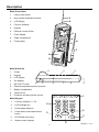
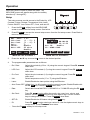
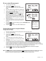
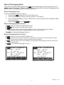
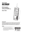
User's Guide IR Thermometer Printer / Datalogger with External Contact Probe Model 42582 F1 F2 F3 ON/O FF Line Feed F4 Introduction Congratulations on your purchase of the Extech 42580 IR Thermometer Printer-Datalogger. This device measures temperature with the non-contact IR sensor and the external contact probe. The built-in Datalogger feature stores up to 12,000 readings. The readings can be displayed directly on the meter or can be for transferred to a PC. The Printer provides a hard copy of stored readings. Careful use of this meter will provide years of reliable service. Safety Use caution when the laser pointer beam is on Do not point the beam toward anyone's eye or allow the beam to strike the eye from a reflective surface Do not use the laser near explosive gases or in other potentially explosive areas 2 42582-EN v6.1 07/13 Description Meter Front Panel 1. Laser pointer beam 2. Non-contact temperature sensor 1 3. LCD Display 2 4. Function Softkeys 5. Keypad 6. External Contact Probe 7. Probe Handle 8. Paper compartment 9. Printer paper 3 F1 F2 F3 4 F4 6 5 ON/OF F Line Feed 7 8 9 Meter Side View 1. 1 Printer 2. Keypad 3. LCD Display 4. AC Adapter 4 6 5 5. RS-232c TTL jack 6. External temperature probe input jack 7. Battery compartment 8. Tripod mount 9. IR sensor and laser pointer source 2 3 7 F1 8 F2 F3 9 F4 1 Meter Keypad 1. Function softkeys F1 – F4 2. LCD backlight key 3. Printer paper advance 4. Power button and measurement button 5. UP-DOWN arrow keys 6. Alpha-numeric keypad 6 2 5 ON / OFF Line Feed 3 4 3 42582-EN v6.1 07/13 Operation Press the ON/OFF button to power the meter. The WELCOME screen will appear along with four softkey selections (F1 through F4): Setup Two setup screens provide access to the Emissivity, LCD Contrast, Printer Contrast, Temperature Units, Laser Pointer ON/OFF, Auto Power OFF, Clock, and user ID. 1. Press the F4 SET softkey from the WELCOME screen to access the first setup screen. See below. 2. Press F4 NEXT to access the second setup screen from the first setup screen. Press Back to return to setup screen 1. Emi. Rate: LCD Cont. Prn Cont. Unit: Laser: Auto Off: EXIT EDIT 0.95 (1 - 5): 3 (1 - 9): 5 o C Enable 20 mins Enable PRN Set Clock: DD-MM-YY HH:MM:SS 07-07-05 02:10:20 Set ID: Enable ID: ACME CORP. EXIT NEXT MAIN SETUP SCREEN 1 3. EDIT PRN BACK MAIN SETUP SCREEN 2 Press the ▲or▼ key to move the 1 cursor to the desired position. 4. The programmable parameters are as follows: • Emi. Rate: Adjust the emissivity (0.0 to 1.0) using the numeric keypad. Press F4 ENTER when done. • LCD Cont: Adjust the LCD contrast (1-5) using the numeric keypad. Press F4 ENTER when done. • Prn Cont: Adjust the print contrast (1-9) using the numeric keypad. Press F4 ENTER when done. • Unit: Select temperature units (°C or °F) using the F2 button. • Laser: Enable/Disable the laser pointer using the F2 button • Auto Power OFF: Adjust from 1 to 20 minutes using the numeric keypad. Enable/Disable with the F2 EDIT key. Press F4 ENTER when done. • Date: Select date format MM: DD:YY, DD:MM:YY or YY:MM:DD using the F2 EDIT key. • Set Clock: Press F2 EDIT to begin editing the month, day, year, hour, minute, and second. Use the ENTER key to move from digit to digit. Use the numeric keys to change the number. Press F4 ENTER when done. • SET ID: Enable/Disable the ID feature using the F2 EDIT key. • ID: Press F2 EDIT to begin entering a custom ID. Use the alpha-numeric keys to create the ID. Press F4 ENTER when done. • Press the F1 EXIT softkey to exit setup mode. 4 42582-EN v6.1 07/13 IR non-contact Measurements 1. Turn the instrument ON. 2. Press the F1 MEAS softkey from the WELCOME screen to enter the measurement mode 3. Point the meter at the surface to be measured. 4. Press and hold the ON button to take a reading while pointing toward the target. 5. Press F3 LASER during measurements to turn the laser pointer ON or OFF. The icon appears when the laser is on. Note that if the Laser is disabled in the SETUP mode, it will not light. Refer to the SETUP section to enable the Laser function.. 6. Release the ON key to hold the measurement on the LCD when the measurement session is finished. 7. Press F4 PRN to print the reading. Use the LINE FEED button to advance the paper. 8. Ext: 35.7 IR: 35.7 Press F1 EXIT to return to the WELCOME screen. o o C C 07-14 03:49:34 Contact Measurements using the Remote Temperature Probe Sample Printout 1. Plug the external probe into the probe jack on the side of the meter. 2. Turn the instrument ON. 3. Press the F1 MEAS softkey from the WELCOME screen to enter the measurement mode 4. Touch the probe to the surface under test. 5. Read the temperature on the LCD next to EXT (external) 6. To use the probe to find an emissivity setting for a particular surface, take an IR measurement and a probe measurement of the same surface, noting the readings. Then adjust the emissivity so that both the IR and the contact probe readings match. Now the emissivity is properly set for that particular surface. IR readings of that surface will be of the highest accuracy possible with this instrument. 7. Press F4 PRN to print the reading. Use the LINE FEED button to advance the paper. 8. Press F1 EXIT to return to the WELCOME screen. Note: The CALI softkey is used to calibrate the external temperature probe to the meter. If this feature is accidentally entered, press and hold the EXIT softkey to exit the mode. A calibration procedure and probe calibration data is required to perform this procedure. 5 42582-EN v6.1 07/13 Manual Datalogging Mode This instrument has two datalogging modes, MEM Manual Datalogging (99 records maximum) and LOG Automatic Datalogging (12,000 records maximum). Data saved in the Manual Datalogging mode can be recalled in the display, printed or transferred to a pc. Manual Datalogging basics To take a reading and store it in memory: 1. Press the F2 MEM softkey from the WELCOME screen. 2. Use the arrow buttons to select a memory location (1 through 99). 3. Press and hold the ON key to take a measurement as previously described. Release the ON key to end the test. 4. Press the F4 SAVE or the F1 ABORT key. Manual Datalogging Display Screen 1 F1 EXIT: Press to return to the WELCOME screen F2 MEAS Press to enter the measurement mode. F3 EDIT: Press to begin customizing the header in the current memory location. Header customization is covered in a dedicated section later in this manual. F4 NEXT Go to Manual Datalogger Screen 2. Manual Datalogging Display Screen 2 F1 EXIT: Press to return to the WELCOME screen F2 CLR: Press for one second to erase the current memory location. Press and hold for longer than one second to erase all records currently held in memory. F3 PRN: Press to print one or more readings. The instrument will prompt the user for a start and end memory point. F3 BACK: Go to Manual Datalogger screen 1. 01: 07-06 05:42:50 o Ext: 82.0 F o Ir: 82.0 F 02: 07-06 05:42:55 o Ext: 82.0 F o Ir: 82.0 F EXIT MEAS EDIT 01: 07-06 05:42:50 o Ext: 82.0 F o Ir: 82.0 F 02: 07-06 05:42:55 o Ext: 82.0 F o Ir: 82.0 F NEXT EXIT MANUAL DATALOG SCREEN 1 CLR PRN BACK MANUAL DATALOG SCREEN 2 6 42582-EN v6.1 07/13 Viewing Stored Readings 1. From the WECLOME screen, press the F2 MEM softkey 2. Use the Arrow keys to scroll through the memory locations and view the stored data. 3. Press the F1 EXIT softkey to return to the WELCOME screen. Printing Stored Data 1. Press F2 MEM from WELCOME screen to proceed to Manual Datalogger screen 1. 2. Press F4 NEXT to proceed to Manual Datalogger screen 2. 3. Use the Arrow keys to scroll to a memory location 4. Use the F3 PRN softkey to print a data record. Erasing Data 1. Press F2 MEM from the WELCOME screen to go to Manual Datalogger screen 1. 2. Press F4 NEXT to proceed to Manual Datalogger screen 2. 3. Use the Arrow keys to scroll to a memory location. 4. Momentarily press the F2 CLR softkey to erase the selected memory location. 5. Press and hold F2 CLR to erase all readings in the Manual datalogger. Answer YES when prompted to erase ALL recorded readings. Press NO to abort. 6. Press F1 EXIT to return to the WELCOME screen. Customizing a Memory Location Header in the Manual Datalogging mode The Header for each Memory location is the Date and Time stamp. To customize a header, follow the steps below: 1. Press F2 MEM from the WELCOME screen. 2. Use the Arrow keys to select a memory location. 3. Press F3 EDIT to begin editing. 4. Use the Arrow keys to step forward and backward in the header line (characters will not be erased) 5. Use the F3 BACK softkey to step backward (erasing characters while stepping). 6. Use the Alphanumeric keypad to compose a header. For example, press the ‘2’ key and a window with the characters related to the ‘2’ key will appear (namely, 2abcABC as shown in the diagram). Then use the ‘2’ key again to scroll through the character list. When the desired character is highlighted the meter will automatically place that character in the header. 7. The F2 CLR softkey is used to erase the header. 8. The F4 ENTER softkey is used to save the header. 01: o T: 82.0l F 2abcABC ABORT CLR BACK ENTER HEADER EDITING 7 42582-EN v6.1 07/13 Automatic Datalogging Mode In the LOG Automatic Datalogging mode the Model 42580 can automatically measure and store 12,000 readings at a programmed sample rate. Data saved in the Automatic Datalogging mode can be recalled in the display, printed or transferred to a PC. Press the F3 LOG softkey from the WELCOME display to access LOG screens 1 and 2: Log Screen 1 Press F3 LOG from the WELCOME screen to access LOG SCREEN 1. F1 EXIT: Return to the WELCOME screen F2 START: Begin automatic Datalogging at the pre-set sampling interval. Datalogging will begin at the date/ time programmed in the SETUP mode. F3 SET: Setup mode. F4 NEXT: Advances to LOG SCREEN 2: Log Screen 2 F1 LOG: Previous Page (previous 100 stored readings) F2 N-PG: Next Page (next 100 stored readings) F3 PRN: Print page F4 BACK: Return to Log Screen 1 Automatic Datalogging SETUP mode From LOG SCREEN 1, press the F3 SET button to enter the configuration screen: BEGIN: Date when datalogging will automatically begin START: Time of day that datalogging will begin END: Date when datalogging will end SUSPEND: Time of day that datalogging will stop each day RATE: Sampling interval (time between recorded readings) EXPECT: Total memory capacity (12,000) REMAIN: Memory locations remaining 00001:12-05 18:45:00 o T: 82.0l F 00002:12-05 18:45:10 o T: 82.0l F 00003:12-05 18:45:20 o T: 82.0l F EXIT START SET NEXT LOG SCREEN 1 00001:12-05 18:45:00 o T: 82.0l F 00002:12-05 18:45:10 o T: 82.0l F 00003:12-05 18:45:20 o T: 82.0l F P-PG N-NP PRN BACK LOG SCREEN 2 Begin: Start: End: Suspend: Rate: Expect: Remain: EXIT EDIT 01-01-05 00:00:01 02-02-05 23:59:59 15 secs 12000 Points 11900 Points VIEW NEXT AUTO DATALOGGER SETUP 1 The two SETUP screens are almost identical; only the softkeys are different (see diagrams). The softkey functions for both SETUP screens are as follows: Begin: 01-01-05 EXIT: Returns to WELCOME screen. Start: 00:00:01 EDIT: Select display field for editing. End: 02-02-05 VIEW: Calls up the stored readings log. Suspend: 23:59:59 15 secs Rate: NEXT: Switches to SETUP screen 2. Expect: 12000 Points START: Activates the datalogger Remain: 11900 Points CLR: Erases all readings stores in the automatic datalogger memory. START CLR PRN BACK PRN: Prints the datalogger memory record AUTO DATALOGGER SETUP 2 BACK: Return to the SETUP screen 1. 8 42582-EN v6.1 07/13 To edit the fields in datalogger SETUP Screen1: 1. Use the up and down arrow keys to scroll through the parameters. 2. When a parameter is highlighted, use the F2 EDIT softkey to open it for editing. 3. Use the alphanumeric keypad to edit the parameter. 4. Press the F4 ENTER softkey to save changes. Press F1 ABORT to cancel changes. 5. Press the F1 EXIT softkey to return to the SETUP screen. Recording Data in the Automatic Datalogging Mode 1. After configuring the datalogger using the SETUP screen as described previously, place the meter in position to take readings (a tripod mount is provided on the rear of the instrument for convenience). 2. Press F3 LOG from the WELCOME screen and then press F2 START. 3. Recording will begin on the date and time programmed at the BEGIN and START lines in the SETUP screen. 4. The Datalogger will record everyday from the START time to the SUSPEND time. The last day that datalogging will take place is the date programmed in the END line. 5. When the logging begins, the screen should indicate LOGGING... 6. If the screen does not indicate logging at the programmed start time, make sure the START key is pressed. Also check the section below entitled “Automatic Datalogging START and END date considerations” for troubleshooting. 7. To stop logging before the programmed SUSPEND time, press the F1 STOP softkey. 8. While logging, view data records by pressing F4 VIEW. 9. To print data from the list, press the F1 STOP, the F4 NEXT and then press the F3 PRN softkey. Press the F2 YES softkey when the PRINT? display appears. 10. To clear (erase) the recorded data, access the LOG mode from the WELCOME screen. Select SET, NEXT and then press and hold the CLR (clear) softkey until the display prompts for confirmation. Select YES to delete all records, or NO to abort the clearing process. Automatic Datalogging START and END Date Considerations 1. If the START date is set to a date before the current date, the datalogger will start the moment the START softkey is pressed. 2. The datalogger will not start logging if the END date is earlier than the current date. 9 42582-EN v6.1 07/13 Field of View The meter’s field of view is 8:1, meaning that if the meter is 8 inches from the target, the diameter of the measurement spot (target) is 1 inch. Other distances and spot sizes are shown below in the field of view diagram. Refer to the chart printed on the meter also for more information. Diameter of Spot 0.5” 2” 1” 4” Laser pointer 4” 8” 16” 32” Distance from Object IR Measurement Notes 1. The object under test should be larger than the spot (target) size (use the diagram above and the diagram printed on the side of the meter to calculate the spot size). 2. If the surface of the object under test is covered with frost, oil, grime, etc., clean before taking measurements. 3. If an object's surface is highly reflective apply masking tape or flat black paint before measuring. 4. The meter may not measure accurately through transparent surfaces such as glass. 5. Steam, dust, smoke, etc. will affect measurements. 6. The meter compensates for deviations in ambient temperature. It can, however, take up to 30 minutes for meter to adjust to extremely wide ambient temperature changes. 7. To find a hot spot, aim the meter outside the area of interest then scan across (in an up and down motion) until the hot spot is located. 10 42582-EN v6.1 07/13 Specifications General Specifications Display Backlit Multi-function LCD Over range indication "-------" appears on the LCD Printer 38mm Printer PC Interface RS-232C (TTL level) Datalogger memory 12,000 readings Low battery indication Battery symbol appears on the LCD Power supply Four (4) 1.5V ‘AA” batteries or optional 9V (1000mA) adapter Operating current 500mA (printing), 6mA (IR active), 2mA (IR standby) Auto Power OFF Adjustable from 1 to 20 minutes Operating Temperature 32 to 122 F (0 to 50 C) o o Operating Humidity 90% Relative Humidity maximum Dimensions/Weight 8.2 x 2.8 x 2.1” (208 x 70 x 53mm) / 9.2 oz. (260g) with battery IR Measurement Specifications o o IR Measurement ranges -40 to 932 F (-40 to 500 C) Accuracy: -4 to 749ºF (-20 to 399 C); ±(2% of reading + 2 digit) or ±4ºF/2ºC (whichever is greater) o o -40 to -3ºF (-40 to -19 C); ±6ºF/3ºC o 750ºF to 932ºF (400 to 500 C); ±(4% of reading + 2 digit) Resolution o o 0.1 for displays <212 , otherwise 1 o o Repeatability ±1 IR distance ratio 8:1 Response time 0.2 seconds Emissivity Adjustable from 0.3 to 1.0 External Probe Measurement Specifications o o Probe Measurement range -4 to 302 F (-20 to 150 C) Accuracy: o -4 to 32ºF (-20 to 0 C); ±2.2ºF (1.2ºC) o 33 to 122ºF (1 to 50 C); ±1.4ºF (0.8ºC) o 123 to 212ºF (51 to 100 C); ±2.8ºF (1.6ºC) o 213 to 302ºF (101 to 150 C); ±5.4ºF (3ºC) Resolution o o 0.1 for displays <212 , otherwise 1 11 o 42582-EN v6.1 07/13 Maintenance Cleaning Wipe instrument with damp cloth as needed. Do not apply solvents or abrasives to the meter. Store in a cool dry place with the batteries removed. Battery Replacement When the batteries weaken, the LCD display will dim or go completely blank. To replace the batteries, open the rear battery compartment and insert four (4) new 1.5V ‘AA’ batteries with correct polarity position. Paper roll replacement When the paper roll is depleted, flip up the paper compartment lid, feed the paper through the paper slit, and feed the paper using the Line Feed button. Place the roll in the compartment and snap the compartment cover shut preventing the paper from falling out. Hint: Folding the paper into a point allows the paper to “catch” a bit easier when feeding it through the slit (see diagram). New paper rolls are available through Extech instruments and Extech distributors. NOTE: Thermal paper prints on only one side. Ensure paper is positioned properly as shown in diagram. Fold paper as shown when feeding new roll 12 42582-EN v6.1 07/13 Emissivity Considerations The amount of IR energy emitted by an object is proportional to an object's temperature and its ability to emit energy. This ability is known as emissivity and is based upon the material of the object and its surface finish. Emissivity values range from 0.1 for a very reflective object to 1.00 for a flat black finish. The 42580 senses IR energy and calculates the temperature based upon the amount of IR energy it receives using a factory default emissivity setting of 0.95 (this setting covers 90% of applications). Most organic materials and painted or oxidized surfaces have an emissivity factor of 0.95. Inaccurate readings will result from measuring shiny or polished metal surfaces which have emissivity factors other than 0.95. To compensate for polished/shiny surfaces, cover the surface with masking tape or flat black paint. Allow time, before measuring, for the tape to reach the same temperature as the material underneath it. Emissivity Factors for Common Materials Material under test Asphalt Concrete Cement Sand Soil Water Ice Snow Glass Ceramic Marble Plaster Mortar Brick Emissivity 0.90 to 0.98 0.94 0.96 0.90 0.92 to 0.96 0.92 to 0.96 0.96 to 0.98 0.83 0.90 to 0.95 0.90 to 0.94 0.94 0.80 to 0.90 0.89 to 0.91 0.93 to 0.96 Material under test Cloth (black) Skin (human) Leather Charcoal (powder) Lacquer Lacquer (matt) Rubber (black) Plastic Timber Paper Chromium Oxides Copper Oxides Iron Oxides Textiles 13 Emissivity 0.98 0.98 0.75 to 0.80 0.96 0.80 to 0.95 0.97 0.94 0.85 to 0.95 0.90 0.70 to 0.94 0.81 0.78 0.78 to 0.82 0.90 42582-EN v6.1 07/13 Software System Requirements Hardware Requirements: 486 PC or better with COM 1 and COM 2 Serial ports Operating System Compatibility: Windows TM 95/98/NT/2000/XP Hardware Connection The IR Thermometer connects to a PC with the supplied DB-9 to 3.5mm mini-plug (mono) interface cable. The DB-9 end connects to the PC serial com port. The mini-plug end connects to the IR Thermometer. Software Installation The instructions on how to install the optional software are printed on the Software CD label. After reading the label’s directions, load the software CD in the PC CD-ROM drive. Software Use The instructions for use are provided on the supplied program CD. Refer to the software instruction manual on the CD. 14 42582-EN v6.1 07/13 Warranty FLIR Systems, Inc. warrants this Extech Instruments brand device to be free of defects in parts and workmanship for one year from date of shipment (a six month limited warranty applies to sensors and cables). If it should become necessary to return the instrument for service during or beyond the warranty period, contact the Customer Service Department for authorization. Visit the website www.extech.com for contact information. A Return Authorization (RA) number must be issued before any product is returned. The sender is responsible for shipping charges, freight, insurance and proper packaging to prevent damage in transit. This warranty does not apply to defects resulting from action of the user such as misuse, improper wiring, operation outside of specification, improper maintenance or repair, or unauthorized modification. FLIR Systems, Inc. specifically disclaims any implied warranties or merchantability or fitness for a specific purpose and will not be liable for any direct, indirect, incidental or consequential damages. FLIR’s total liability is limited to repair or replacement of the product. The warranty set forth above is inclusive and no other warranty, whether written or oral, is expressed or implied. Calibration, Repair, and Customer Care Services FLIR Systems, Inc. offers repair and calibration services for the Extech Instruments products we sell. NIST certification for most products is also provided. Call the Customer Service Department for information on calibration services available for this product. Annual calibrations should be performed to verify meter performance and accuracy. Technical support and general customer service is also provided, refer to the contact information provided below. Support Lines: U.S. (877) 439‐8324; International: +1 (603) 324‐7800 Technical Support: Option 3; E‐mail: [email protected] Repair & Returns: Option 4; E‐mail: [email protected] Product specifications are subject to change without notice Please visit our website for the most up‐to‐date information www.extech.com FLIR Commercial Systems, Inc., 9 Townsend West, Nashua, NH 03063 USA ISO 9001 Certified Copyright © 2013 FLIR Systems, Inc. All rights reserved including the right of reproduction in whole or in part in any form www.extech.com 15 42582-EN v6.1 07/13