1
High Availability
N+1 Tips and Configuration for the uBR10012
Purpose
This document is meant to assist with the setup, wiring, and configuration of the N+1 solution according
to Cisco’s recommended design. The components that must be configured, in addition to the wiring
schemes, are the following:
1. uBR-RFSW RF Switch
2. uBR10012
Table of Contents
Introduction
RF Switch
RF Switch Cabling
uBR10012 with MC5x20 Cards
More Pictures
N+1 for uBR10012 with MC28C Cards
RF Switch
RF Switch Cabling
uBR10012 with MC28C Cards
HCCP Features
Synchronized & Non-Synchronized Commands
Testing Modems for Failover Capabilities
HCCP Commands
Testing and Troubleshooting Command Quick Lookup
Introduction
The uBR100012 can be setup as 1 card protecting 7 others. This helps with economics because it now
provides 7+1 availability, and also passes necessary requirements for PacketCable. One RF Switch is
required when using MC28C cards. Two RF Switches are needed when using MC5x20 cards.
Note: One RF Switch can be used in 4+1 mode when using MC5x20 cards if only four Working and one
Protect linecards are used.
Tip: The cabling side of all the units is considered the rear view. The reference design is to mount all the
units flush to the front. The VCom upconverter only has mounting brackets on the front, but the
10K and RF Switch can be mounted flush from the front or rear. It’s recommended to use Slot 5/1
for the Protect linecard as the wiring will be optimized when attaching the RF Switch.
RF Switch
The reference design is wired with DS 0’s MAC domain on the left side of the top RF Switch’s header
and DS 1’s MAC domain on the right side of that same header. DSs 3 & 4 MAC domains are wired the
same, but in the bottom RF Switch. DS 2’s MAC domain is wired in ports E & L of both RF Switches
and port G of the bottom RF Switch for the DS. The color code is very important because the cable kits
are pre-made for Cisco’s reference design for the 10K, 5x20 cards, and RF Switches. The 5x20 cards
install vertically in the 10K, so cables are cut to a specific length for wiring. Refer to: Rack-Mounting
and Cabling the Cisco RF Switch with the Cisco UBR10-MC5X20S-D card;
http://www.cisco.com/univercd/cc/td/doc/product/cable/rfswitch/5x20qsc.htm for more information.
When the 5x20 is wired up with this color scheme, USs 0, 1, 2, & 3 for the first MAC domain will be red,
white, blue and green and the DS associated with it will be red. USs 0, 1, 2, & 3 of the second MAC
domain will be yellow, violet, orange, and black and the DS associated with it will be white. Be sure to
wire the RF Switch header with 4 US on the left and 4 on the right. Put the DS, red wire on the left in the
second hole from the bottom. Put the DS, white wire on the right side of the header next to the red.
The Switch can be operated in 2 separate modes, either as an 8+1 Switch or as two, 4+1 Switches. In the
case of the uBR10K with 5x20 cards, we will operate it in the 8+1 mode, but really as 7+1 because there
are only 8 linecards in the 10K and one of those most be used as a “Protect” card. Also, because we are
using 5x20 cards, we will be technically doing five, 7+1 redundancy schemes on the MAC domain level.
Warning: DSs 0 & 1 are tied to the same JIB(ASIC) and will failover together. DSs 2 & 3 are tied to the
same JIB and will failover together. DS 4 is on its own JIB.
Note: If HCCP is not configured on an interface that shares a JIB with another interface that is
configured, it won’t failover.
RF Switch Cabling
Part numbers:
Cisco Black header for N+1 switch;
PN# MCXHEADERBK
MCX fixed pin for field termination;
PN# MCXFP
F connector for field termination;
PN# ASFP
Crimper for MCXFP; .213 Hex crimp;
PN# C47-10120
Crimper for ASFP F connector; .270 Hex Crimp; PN# ACT-270 ~ $35
Stripper for MCXFP; .230 x .125 2-stage strip;
PN# CPT-7538-125
Stripper for ASFP; .250 x .250 2 stage strip;
PN# CPT-7538 ~ $35
CablePrep: 1-800-394-4046, http://www.cableprep.com/
www.whitesandsengineering.com or www.tvcinc.com
MCX Jack to F Jack Adapter;
PN# 531-40137
Switch to 2x8 card cable kit. MCX to FP 47.5"
PN# 74-2765-02
Switch to Plant side cabling kit MCXP to FP 10 m PN# 74-2961-01
CMTS-to-Switch; CAB-RFSW520TIMM, 1-meter; PN# 74-2983-01 or PN-7814515-01
Switch-to-Plant; CAB-RFSW520TPMF, 3-meter; PN# 74-2984-01 or PN-78-147111-01
It is suggested to get the cable kits from WhiteSands for all Inputs, Protect and Outputs. WhiteSands
Engineering can be reached at http://www.whitesandsengineering.com. The new output cable kit (742984-01) will contain 2, 3-meter cable bundles of 10, MCX to F, a 3-meter bundle of 5, and a bag of 25
extra f-connectors. The cables can be ordered from WhiteSands with female F-connectors also.
Tip: Test the connector and cabling continuity before crimping the connector. You may need to test
through the Switch unless an adapter (531-40137) is used. Remember to test DS ports from
upconverter output to Switch output and test US ports from CMTS to Switch output. You don’t
have to install the cables in the header for testing purposes. I’m not sure a simple dc-continuity test
will suffice. I recommend a full RF spectrum sweep from 5-70 MHz for US ports and 50-870 MHz
for DS ports.
uBR10012 with MC5x20 Cards
These bullet points indicate the situations that are tracked for failover initiation. These are considered the
most prevalent issues that could allow modems to drop offline.
• Shut down the active cable interface (works, but not supported)
• On-line insertion removal (OIR) of active line card
• Software CLI based commands – hccp “g” switch “m”
• Software crash of the active line card
• DS cabling failure via “KeepAlive” feature
• Resetting the line card - Hw-module subslot x/y reset
• Power outage on Working linecard – cable power off x/y
A DS failure could be from a bad internal upconverter or cable between the 10K and RF Switch. The
Keepalive feature tracks all communication on all the US ports of a particular MAC domain. When there
is no communication what-so-ever, a failover will initiate based on some user-configurable thresholds and
timers.
Since the 5x20 card is really 5, 1x4 MAC domains, you can make switch groups based on MAC domains.
A MAC domain is 1 DS and all its associated USs. These MAC domains are user-configurable with the
virtual interface feature released in 15BC1 IOS, but are statically set as 1x4 MAC domains by default.
Note: If an upstream connector is assigned for virtual interface configurations, the entire linecard will
failover when a fault occurs instead of single MAC domains or ASIC companions.
The 5x20 card is labeled with USs 0-19 and DSs 0-4. DS 0 is associated with US 0-3, DS 1 is tied to USs
4-7, etc. The configuration in the CMTS is still considered to be USs 0-3 regardless of which MAC
domain. If you want to configure DS 4, US 17 would actually be considered US 1 since DS 4 uses USs
16-19 and 16 refers to US 0, etc.
If you shut down the Working interface, the protocol will initiate a failover via the configuration file. A
failover is not initiated by US ports being “shut”. Pulling an upstream cable from ONE port on a line
card is not generally considered a valid "event" to cause an N+1 line card failover. It is essentially
impossible to distinguish this from a disconnected attenuator in a fiber node or amplifier (used for
operational maintenance). Pulling the linecard out of the chassis, disconnecting the downstream cable
between the linecard & RF Switch, or some other software or hardware type fault on the card itself are all
considered valid "N+1" failover events.
On the uBR10K, you could even use the linecard power down command, which cuts power to the line
card, and thus causes a failure.
10K#cable power off ?
<slot>/<card> slot [5-8] card [0/1]
One interface will be designated as a “Protect” interface and all the commands will be configured in that
interface to backup all the interfaces in its Group. If a linecard is removed, one or more MAC domains
will be removed and a “Protect” card will be initiated to back it up. The configuration in the 10K will
make the appropriate RF Switch relays to switchover.
Warning:
Non-synched cable interface commands need to be pre-configured. These commands
should be the same on all the Members of an HCCP Group. Refer to the “Synchronized
Commands” section later in this document.
Tip: Be sure to always review your config when updating IOS to the latest code. Make sure you
configure the Working interfaces before the Protect interface(s).
Warning: The DS frequency in the uBR config does have an affect when doing N+1 redundancy. The
internal upconverter needs to know the DS frequency or it won’t activate.
Tip: If some US ports are combined for a dense-mode combining scenario, they could be combined at the
CMTS to free up some US ports on the RF Switch. This means, instead of taking one reverse and
splitting to feed 2 US ports before the Switch, do it after the Switch and before the CMTS.
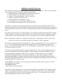
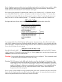
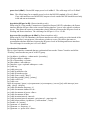
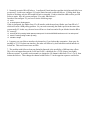
Figure 1 is a picture of the uBR10K mock-up wired with the Belden cable with MCX-connectors and
color-coded cable. Notice the cable lengths and the extra cable bracket for added support. The bracket
makes it look more organized and keeps the cables away from the fan outlet. 7+1 high availability
provides protection for 140 US ports and 35 DS ports. The special mini-coax and MCX connectors use
less space than traditional coax and connectors, and the rugged Universal Cable Holder can easily
disconnect up to 10 cables at once.
This setup uses 1 uBR10K and 2 RF Switches. Since this is really 7+1 redundancy, one of the 8
“Working” inputs on the RF Switch will be unused. This may be used for future wiring or maybe testing
purposes.
Figure 1 – uBR10012 with MC5x20 Cards
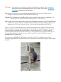
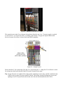
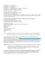
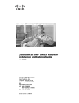
Figure 2 is the Cisco reference design shown from the rear view. Look closely at the cable color coding.
If a power supply is needed to convert AC to –48 Vdc for the 10K, it is usually on the bottom. No gaps
are required between the devices, because all air-flow is front-to-back and NEBS compliant.
Figure 2 – Sample Layout
We are using interfaces 5/1/0 through 5/1/4 as “Protect” groups 1-5. 5/1/0 is protecting 8/1/0, 5/1/1 is
protecting 8/1/1, etc. Using Slot 5/1 for Protect is easier for wiring since the Protect header of the RF
Switch is located in the center.
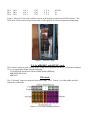
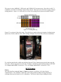
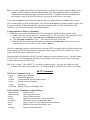
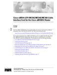
Figure 3 is a picture of the whole setup. The cable kits are made with precise lengths of cabling for the
RF Switches, and 5x20 cards. Other racking techniques may be possible, but not recommended.
Figure 3 – Full N+1 Setup
More Pictures
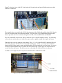
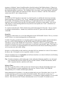
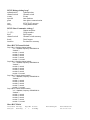
Figure 4 is a picture of the new dense connector for the 5x20 card. On the left is a 5x20 card wired up
with RG-6 cable, Belden cable with F-connectors and 2 slots for the dense connector blades.
Figure 4 – MC5x20D Dense Connectors
Even with the card wired up, the LEDs are still viewable. This will be much easier to service than 25 Fconnectors on one linecard. This new dense connector will be very robust with strain relief, one-way
insertion, and heavy construction.
Example of hccp table:
hccp "g" working "m" The first number is the group (DS associations) and the second number is the
member. A member number was chosen to match the uBR subslot for easier identification.
Interface Subslot
80
81
70
71
60
61
50
51
DS 0 1 80 1 81 1 70 1 71 1 60 1 61 1 50 P1 of RF Switch 2 (Top Switch)
DS 1 2 80 2 81 2 70 2 71 2 60 2 61 2 50 P1 of RF Switch 2 (Top Switch)
DS 2 3 80 3 81 3 70 3 71 3 60 3 61 3 50 P1 of RF Switch 1 & 2
DS 3 4 80 4 81 4 70 4 71 4 60 4 61 4 50 P1 of RF Switch 1 (Bottom Switch)
DS 4 5 80 5 81 5 70 5 71 5 60 5 61 5 50 P1 of RF Switch 1 (Bottom Switch)
The RF Switch slot number will start with 1 moving from left to right.
In 4+1 mode it gets more complicated. If we follow our suggestion of only using the following interfaces:
The third number will be the RF Switch slot number used for the channel-switch config. In 4+1 mode
slot 5 is considered to be slot 1 again.
DS 0
DS 1
80
1 80 1
2 80 1
81
1 81 2
2 81 2
Interface Subslot
70
71
1 70 3
1 71 4
2 70 3
2 71 4
51
P2
P2
DS 2
DS 3
DS 4
3 80 1
4 80 1
5 80 1
3 81 2
4 81 2
5 81 2
3 70 3
4 70 3
5 70 3
3 71 4
4 71 4
5 71 4
P2 & P1
P1
P1
Figure 5 is how the 5x20 cards would be wired up with the dense connectors and 2 RF Switches. The
5x20 cards will have built-in upconverters and s-card capability for advanced spectrum management.
Figure 5 – 5x20 N+1 Setup
N+1 for uBR10012 with MC28C cards
This section is meant to assist with the setup, wiring, and configuration of the N+1 solution according to
Cisco’s recommended design using the following:
VCom HD4040 upconverter with an SNMP module (HD4008)
uBR-RFSW RF Switch
uBR10012
RF Switch
The 8 “Working” inputs are numbered from left to right. The 2 “Protect” are in the middle and the 8
outputs are on the right.
Figure 6 - RF Switch Numbering Scheme
Figure 7 is the back view of the RF Switch with the 14-port header and special Belden mini-coax cable
with MCX connectors.
Figure 7 - RF Switch and Upconverter Cabling
The example above was wired with 1 MAC domain on one side of the header and the other MAC domain
of a 2x8 card on the other side of the same header. The color code is very important because the cable
kits are pre-made for Cisco’s reference design for the 10K, 2x8 cards, RF Switch and HD4040.
The 2x8 cards install vertical in the 10K, so cables are cut to a specific length for wiring. The following
color codes are used in order; red, white, blue, green, yellow, purple, orange, black, gray, and brown.
When the 2x8 is wired up with this color scheme, USs 0, 1, 2, & 3 for the first MAC domain will be red,
white, blue and green and the DS associated with it will be gray. USs 0, 1, 2, & 3 of the second MAC
domain will be yellow, purple, orange, and black and the DS associated with it will be brown. Be sure to
wire the RF Switch header with 4 US on the left and 4 on the right. Put the gray wire on the left in the
second hole from the bottom. Put the brown wire on the right side of the header next to the gray.
It’s hard to see in Figure 8, but the upconverter and Switch are in the Protect mode.
Figure 8 - RF Switch and Upconverter – Front View
The far 2 right upconverter modules have been disabled and modules 9 and 10 have been enabled. All the
Switch LEDS are amber/yellow except the modules that weren’t used in the bitmaps, which was the 5th
module down on the left and the 5th and 7th modules on the right.
The Switch can be operated in 2 separate modes, either as an 8+1 Switch or as 2, 4+1 Switches. In the
case of the uBR10K with 2x8 cards, we will operate it in the 8+1 mode, but really as 7+1 because there
are only 8 linecards in the 10K and one of those most be used as a “Protect” card. Also, because we are
using 2x8 cards, we will be technically doing 2, 7+1 redundancy schemes on the MAC domain level.
RF Switch Cabling
The Input cable kit will work on the Output if you use the 2 extra separate cables for the DS.
Input Cable Kit Part NumbersQuantity
47.5BKASFP/MCXFPWS943
1
18GYASFP/MCXFPWS940
1
18BRASFP/MCXFPWS940
1
MCXHEADERBK
1
Output Cable Kit Part Numbers
Quantity
394BKASFP/MCXFPWS943
1
394GYASFP/MCXFPWS940
1
394BRASFP/MCXFPWS940
1
MCXHEADERBK
1
ASFP
13
It’s recommended to keep MAC domains visibly separate, but not necessary. We will wire the headers
with 1 MAC domain on one side of the header and the other MAC domain of a 2x8 card on the other side
of the same header. The MAC domain wiring must be the same in all the associated Inputs, Outputs, and
Protect that all belong to the same group.
uBR10012 with MC28C Cards
Since the 2x8 card is really 2, 1x4 MAC domains, you can make switch groups based on MAC domains.
A MAC domain is 1 DS and all its associated USs. A failover group can be considered mac domains and
a member would be associated with linecards.
Warning: Non-synched cable interface commands need to be pre-configured. These commands should
be the same on all the Members of an HCCP Group.
Warning: The DS frequency in the uBR config does have an affect when doing N+1 redundancy. The
external upconverter needs to know the DS frequency from the uBR configuration via SNMP
when a failover occurs. If you leave it blank and a switch-over occurs, the Protect upconverter
module will change its frequency to a potentially wrong frequency. It was originally only for
informational purpose or for the “cable downstream override” feature when multiple DS
frequencies are on the same plant.
This is a picture of the uBR10K wired up with the Belden cable with F-connectors and color-coded cable.
Notice the cable lengths and the extra cable bracket for added support. It’s not needed, but does make it
look more organized and keeps the cables away from the fan outlet.
Figure 9 – uBR10012 with MC28C Cards
This sample layout is the Cisco reference design shown from the rear view. If a power supply is needed
to convert AC to –48 Vdc for the 10K, it is usually on the bottom. No gaps are required between the
devices, because all air-flow is front-to-back and NEBS compliant.
Figure 10 – Sample Layout
Protect interface 5/1/0 is protecting 8/1/0 and 5/1/1 is protecting 8/1/1. Using Slot 5/1 for Protect is easier
for wiring since the Protect header of the RF Switch is located in the center.
Tip: If some US ports are combined for a dense-mode combining scenario, they could be combined at the
CMTS to free up some US ports on the RF Switch. This means, instead of taking one reverse and
splitting to feed 2 US ports before the Switch, do it after the Switch and before the CMTS.
This setup is using 1 uBR10K, 1 RF Switch, and 1 HD4040 VCom upconverter. Since this is really 7+1
redundancy, one of the 8 “Working” inputs will be unused. This may be used for future wiring or maybe
testing purposes. Figure 11 is a blow-up view of the color-coding for the upconverter and RF Switch.
Figure 11 – Wiring Blow-up
Figure 12 is a picture of the whole setup. The cable kits are made with precise lengths of cabling for the
upconverter, Switch, and 2x8 cards. Other racking techniques may be possible, but not recommended.
Figure 12 – Full N+1 Setup
To switch an entire header, which may hold one linecard, 2 MAC domains must switch when using the
2x8 cards. The best way may be to issue the “Tracking” command so each interface points to each other.
Use “hccp 1 track c5/0/0” on interface C5/0/1 and “hccp 1 track c5/0/1” on interface C5/0/0.
HCCP Features
Timers
The cable interface command: hccp “g” timers <hellotime> <holdtime> is for inter-chassis
communication. The “hellotime” is the timer value of the periodic heartbeat message that HCCP
exchanges between the chassis for N+1 redundancy. The Protect chassis keeps sending the Hello
message at “hellotime” interval in milliseconds to check the sanity of the Working chassis. If there is no
Hello-Acknowledgement for more than a time period equal to "holdtime", then it is declared the Working
has failed and initiates a switchover. The “holdtime” has to be at least 3 times larger than the “hellotime”.
The default is 5000 for hello and 15000 ms for hold. The max is 25000 ms. Since the 10K solution is
entirely intra-HCCP, don’t change this timer.
Tracking
By default, an HCCP interface tracks itself. So when Keepalive is enabled and it detects no incoming
upstream packets, it will failover. The “Track” command can also be used to track an uplink interface.
For example, if Working has a dedicated uplink (eg. GE) path and Protect has its own, these uplink
interfaces can be tracked. When one fails, the cable interface will failover to the standby. Since in the
10K solution, it seems Working and Protect may share the same uplink, this “Track” command is not
needed for this scenario.
To switch an entire linecard, 5 MAC domains must switch when using the 5x20 cards. One way may be
to configure virtual interfaces. Another way would be to use the CLI; power off or hw-module reset
commands.
KeepAlive
The purpose of this feature is to cover bad cabling between the CMTS and RF Switch. The way we detect
an HFC failure is to count incoming packets on all upstreams.
If within 3 keepalive periods there is no incoming packets (range requests/response, station maintenance,
data, etc.) on all of USs belonging to one DS, the line protocol will be down and HCCP assumes
something is wrong in that channel and will switchover. Remember, if there is a real HFC problem, the
switchover will occur, but won't do any good because it's still on the same bad HFC plant. This feature is
meant to cover failures in components that are not common between the Protect and Working interfaces
such as upconverters and certain cabling.
Keepalive is off by default on cable interfaces with older IOS, but is defaulted to a value of 10 seconds in
the newer code. Set keepalive as low as possible, which is 1 second.
It may be advantageous to set no keepalive on the Protect interfaces so it doesn’t fail back to the Working
interface if all the modems go offline.
Tip: If routine maintenance will be taking place in the cable plant (balancing amplifiers, etc) and signal
loss is eminent that will affect all the US ports of a MAC domain, "lockout" that interface, and its
ASIC companion interface, until the work is done.
Failover Times
DOCSIS 1.0 specifies 600 ms as DS sync loss, but it doesn't specify what the CM should do after sync
loss. Most CMs don’t re-register immediately after sync loss. Refer to CSCdv71490 UBR10K:
Interoperability of N+1 feature with third party modems.
Station Maintenance for modems is 1 second per modem until you get to 20 modems, then it’s every 20
seconds when there are 20 or more modems in the MAC domain. This used to be set for every 25
seconds. When HCCP is configured, the top number is 15 seconds for a higher probability of a successful
failover. This is because of the T4 timer in modems that is set at 30 seconds. If a modem were to
experience a failover right before its scheduled 20-second station maintenance, it would only have 10
seconds left of its T4 timer. The failover could take slightly longer than this and the modem would go
offline. By making the station maintenance 15 seconds, the worst case scenario will give 15 seconds for a
failover to occur before a T4 timeout on a modem.
Reverttime
The reverttime is configured on Working interfaces and is for the Protect to automatically revert back so
that it has the capacity to serve another failure in case the user forgets to manually switch it back. The
default is 30 minutes. No reverttime sets the command to the default of 30 minutes. To not revert, use
the command no hccp “g” revertive on the Protect interface.
If you set reverttime to 1 minute in the Working interface config, it still takes 3 minutes for the Working
to kick back in. There are 2 minutes of suspend time prior to reverttime. This suspend time is used to
define a singular failure. Any two switchovers happening within this suspend time is considered double
failure. HCCP is best effort in double failure, and non-disruptive service isn’t guaranteed.
If the reverttime is too short, the user may not be able to fix the 3rd party problem and the Protect will
switch back if the Working card is fine.
Note & Tip: Once the suspend time is over, any failure in the Protect interface will switch back if the
Working interface is ok, no matter whether reverttime is over or not. If you OIR the
Protect card, the suspend time is bypassed, but inserting the card will take 2 minutes to
reboot anyway. Another way to fail from Protect back to Working immediately would be
to run the command cable power off 5/1 then cable power on 5/1.
You can do show hccp brief to see how much time is left in the counter.
uBR # sh hccp brief
Interface Config
Ca5/0/0
Working
Ca5/1/0
Protect
Grp Mbr Status
1
1
standby
1
1
active
WaitToResync
00:00:45.788
WaitToRestore
00:01:45.792
00:01:45.788
After 1 minute, static sync takes place and the standby sync's up to the database of the active. So if you
use, OIR, or hw-module reset to trigger a failover, you may do so right after it finishes static sync.
If you disconnect the DS from a Working card, the Protect will kick in properly after 3 keepalives have
expired. A DS failure will not be tracked if Keepalive is off. Once the reverttime and 2 minute suspend
time are up, it will NOT go back to the Working because the failure was from Keepalive. You may
choose not to revert to Working by configuring no hccp “g” revertive on the Protect interface. If you
still allow Protect to revert, you may configure a big revert time on the Working interface (up to 65k
minutes) and manually issue hccp “g” switch “m” once you feel comfortable to switch back.
Downstream RF Power
The downstream RF output power will be synchronized from the Working to Protect interface in BC2
code and greater. It may be preferable to not sync the level over and allow the user to pre-configure the
Protect for a set output level. It may also be preferred to set a delta on the Protect compared to the
Working interface. A command configured on the Protect interface exists to achieve this.
cable downstream rf-power {power-level | hccp-delta (diff-pwr) | hccp-override (override-pwr)}
power-level (dBmV): Desired RF output power level in dBmV. The valid range is 45 to 63 dBmV.
Note: The official range for acceptable power levels in the DOCSIS standard is 50 to 61 dBmV.
Cisco cable interfaces exceed DOCSIS, but power levels outside DOCSIS should be used only
in lab and test environments.
hccp-delta (diff-pwr in dB): (Protect interfaces only)
When using N+1 Hot standby Connection-to-Connection Protocol (HCCP) redundancy, the Protect
interface adds the diff-pwr value to the current Working interface’s power value when a switchover
occurs. This allows the router to accommodate relative differences between the RF power levels in
Working and Protect interfaces. The valid range for diff-pwr is -12 to +12 dB.
hccp-override (override-pwr in dBmV): (Protect interfaces only)
When using N+1 HCCP redundancy, the Protect interface uses the override-pwr value instead of the
Working interface’s current power value when a switchover occurs. This allows the router to
accommodate absolute differences between the RF power levels in Working and Protect interfaces.
The valid range for override-pwr is 45 to 63 dBmV.
Synchronized Commands
This is a list of interface commands that are synchronized between the “Protect” interface and all the
“Working” interfaces that are part of its HCCP group.
[no] ip address <ip address> <subnet mask> [secondary]
[no] ip helper-address <address>
[no] ip vrf forwarding <vrf name>
[no] mac-address <mac address>
[no] interface <type><optional-whitespace><unit>
[no] cable arp
[no] cable proxy-arp
[no] cable ip-multicast-echo
[no] cable ip-broadcast-echo
[no] cable source-verify ["dhcp"]
[no] cable dhcp-giaddr [ policy | primary ]
[no] cable resolve-sid
[no] cable reset
cable dci-response [ ignore | reject-permanent | reject-temporary | success ][no] cable intercept {macaddr} {dst-ip} {dst-port}
[no] cable downstream frequency <f>
[no] cable downstream channel-id <id>
[no] cable downstream rf-power <dbmv>
[no] cable downstream rf-shut
[no] cable insertion-interval <interval>
[no] cable insertion-interval automatic <min-interval> <max-interval>
[no] cable helper-address <ip-address> ["cable-modem" | "host"]
[no] bundle <n> [ master ]
[no] upstream <n> shutdown
[no] upstream <n> frequency <f>
[no] upstream <n> power-level <dbmv>
[no] upstream <n> concatenation
[no] upstream <n> minislot-size <2-128>
[no] upstream <n> fragmentation
[no] upstream <n> modulation-profile <1st-choice> [<2nd-choice>]
[no] upstream <n> channel-width <hz> <hz-opt2>
[no] ip access-group [<n>| <WORD>] [“in” | “out”]
[no] cable spectrum-group <grp num>
[no] cable upstream <n> spectrum-group <grp num>
[no] cable upstream <n> hopping blind
[no] cab up<#> threshold cnr-profile1 <5-35> cnr-profile2 <5-35> Corr-Fec <0-30> Uncorr-Fec <0-30>
[no] cable upstream <#> hop-priority [frequency | modulation] [frequency | modulation | channel-width]
[no] ip pim sparse-dense-mode
Non-Synchronized Commands that must be pre-configured on the Protect Interface
cable map-advance dynamic/static
cable downstream modulation [256qam | 64qam]
cable downstream interleave-depth [128|64|32|16|8]
[no] keepalive <0-32767>
power-adjust threshold, power-adjust continue, & power-adjust noise
tftp enforce (mark only)
shared secret
arp timeout
cable source-verify lease timer
ip policy route-map
load balance configs
no shut
Note: All configurations will be synchronized in 15 BC2 code and above, except for DS modulation,
annex mode, and DS interleave. These need to be the same on all members of an HCCP group.
The newer IOS code (>12.10 EC1 & BC code) will allow the user to put in a hard-set number for
Dynamic and Static Map Advance, refer to http://www.cisco.com/warp/customer/109/map_advance.html
for a detailed explanation of this command. With this in mind, each interface could have a different Map
Advance setting. If the Working fails over to a Protect with a different setting, the modems may have
difficulty synchronizing Maps. The Initial Maintenance Time Offsets of each modem will be synced over
in IOS code > 12.2(8)BC2. It’s recommended to use the default settings on the Protect of “cable mapadvance dynamic 1000 1800”.
Warning: When adding and removing configurations from live Working line cards, the N+1 architecture
cannot protect the new configuration until it is statically synched to the Protect card. If a
switch-over occurs before the static sync, the application, which was invoked by the new
configuration, could have unpredictable behavior.
To prevent this, lockout the Working line card with hccp {group} lockout {member} then configure the
new commands. When finished, unlock the Working card with hccp {group} unlockout {member}.
This forces an immediate static sync. Resyncs will take place automatically after leaving the cable
interface config mode with the 12.2(11)BC1 IOS release and above.
Tip: After any configuration change on a Working line card, the HCCP re-sync command hccp {group}
resync {member} should be issued on that Working card. This updates the Protect with the new
config and any subsequent switch-over will be successful. It’s good to run this command before
any testing so some of the DOCSIS tables are synced over to the Protect when ready.
You could also shut the Protect interface until the config is completed, then do no shut, but you must
wait 1 minute before a resync will take place. The problem with shutting the Protect interface is there will
be no protection for all the other interfaces it may be protecting while it is shut. The problem with
“lockout” is you may have to initiate it for all the interfaces.
Testing Modems for Failover Capabilities
1. Follow these steps to test downstream SYNC loss duration for which a modem remains online.
A. Telnet to the CLC console with 127.1.1.50 and enable it. “50” represents cable linecard slot 5/0 in
this example. You can also type if-con if server internal is invoked on the 10K.
B. Type: test cable synch delay <msec>. This specifies the msec SYNC loss.
C. From the 10K Exec mode, type the following command: test cable atp <cable interface for the
modem under test> <mac-address of the modem> mac 16
The above command pings the modem first, then stops the SYNC message for the specified duration, and
restarts sending SYNC at 10 ms duration. It pings the modem again to check the connectivity. If this
ping succeeds, the test is considered a success.
Please note that if the ping fails, the ATP test still continues, once the modem recovers. The final output
ATP test "Pass" is not an indication of what we are looking for. We declare the test to fail, if the ping
session after the restart of SYNC fails.
Tip: Type “Control” “Alt or Shift” “6” to stop the ping if necessary. An easier test would be to just
disconnect the cable to the modem for ~ 5 seconds, re-connect, and make sure it doesn’t go offline.
HCCP Commands
HCCP Exec Commands; hccp 1 ?
-bypass
Enter bypass operation
-check
Exit bypass operation
-lockout
Lockout switchover on teaching worker
-resync
Re-sync member's database
-switch
Switchover
-unlockout Release lockout on teaching worker
HCCP Interface Commands; (config-if)#hccp 1 ?
–authentication
Authentication
–channel-switch
Specify channel switch
–protect
Specify Protect interface
–revertive
Specify revert operation on Protect interface
–reverttime
Wait before revert switching takes place
–timers
Specify “hello” & “hold” timers on Protect interface
–track
Enable failover based on interface state
–working
Specify Working interface
HCCP Debugs; debug hccp ?
authentication
Authentication
channel-switch
Channel switch
events
Events
inter-db
inter database
plane
inter-plane communication
sync
SYNC/LOG message
timing
Timing Measurement
HCCP Show Commands; sh hccp ?
|
Output modifiers
<1-255>
Group number
brief
Brief output
channel-switch
Channel switch summary
detail
Detail output
interface
Per interface summary
Show HCCP Channel-Switch
Grp 1 Mbr 1 Working channel-switch:
"uc" - enabled, frequency 555000000 Hz
“rfswitch" –
module 1, normal
module 3, normal
module 5, normal
module 7, normal
module 11, normal
Grp 2 Mbr 1 Working channel-switch:
"uc" - enabled, frequency 555000000 Hz
“rfswitch" –
module 2, normal
module 4, normal
module 6, normal
module 9, normal
module 13, normal
Grp 1 Mbr 7 Protect channel-switch:
"uc" - disabled, frequency 555000000 Hz
“rfswitch" –
module 1, normal
module 3, normal
module 5, normal
module 7, normal
module 11, normal
Grp 1 Mbr 5 Protect channel-switch:
"uc" - disabled, frequency 555000000 Hz
“rfswitch" –
module 1, normal
module 3, normal
module 5, normal
module 7, normal
module 11, normal
Show HCCP Brief
Interface Config
Ca5/0/0
Working
Grp Mbr Status
1
1
standby
WaitToResync
WaitToRestore
00:01:45.792
Ca5/1/0
Protect
1
1
active
00:00:45.788
00:01:45.788
Each module should have a set of objectives.
Show HCCP Detail
HCCP software version 3.0
Cable5/0/0 - Group 1 Working, enabled, forwarding
authentication none
hello time 5000 msec, hold time 15000 msec, revert time 120 min
track interfaces: Cable5/0/0
sync time 1000 msec, suspend time 120000 msec
switch time 240000 msec retries 5
local state is Teach, tran 80
in sync, out staticsync, start static sync in never
last switch reason is internal
data plane directly sends sync packets
statistics:
standby_to_active 5, active_to_standby 4
active_to_active 0, standby_to_standby 0
Member 1 active
target ip address: protect 172.18.73.170, working 172.18.73.170
channel-switch "rfswitch" (rfswitch-group, 172.18.73.187/0xAA200000/8) enabled
tran #: SYNC 72, last SYNC_ACK 4, last HELLO_ACK 5790
hold timer expires in 00:00:11.532
interface config:
mac-address 0005.00e1.9908
cmts config:
bundle 1 master, resolve sid, dci-response success,
downstream - frequency 453000000, channel id 0
downstream - insertion_invl auto min = 25, max = 500
upstream 0 - frequency 24000000, power level 0
upstream 0 - modulation-profile 2, channel-width 3200000 (minislot doesn’t show up, but it is synchronized)
upstream 0 - cnr-profile1 25, cnr-profile2 15
corr-fec 1, uncorr-fec 1
upstream 0 - hop-priority frequency modulation channel-width
sub-interface master config:
ip address 10.50.100.1 255.255.255.0
ip address 24.51.24.1 255.255.255.0 secondary
ip helper-address 172.18.73.16
ip pim sparse-dense-mode
cable helper-address 172.18.73.165
cable arp, proxy-arp,
cable ip-multicast-echo,
cable dhcp-giaddr policy,
Testing and Troubleshooting Command Quick Lookup
10K
test hccp {Group #}{Worker's member id} channel-switch {name} snmp/front-panel
test hccp {Group #}{Worker's member id}{working/protect }fault 1 (simulates an Iron bus fault)
test hccp {Group #}{Worker's member id}{working/protect} failover
test hccp {Group #}{Worker's member id}modem-test ds-signal{name}{mac-addr}{msec}
test cable synch delay {msec delay}
test cable atp {CMTS interface}{mac-addr} mac {test_id}
show hccp; show hccp (brief ; detail; channel-switch)
show ip interface brief; show hccp{Group #}{Worker's member id} modem
hccp {Group #} switch; lockout; resync {Worker's member id}
hw-module {slot}/{subslot} reset
debug hccp authentication; channel-switch; events; plane; sync; timing
RF Switch
test module
config card count{1-14}
sh conf or sh cf
sh mod all
sh dhcp
sh ip
sh switch status {mod #} or sh sw st {mod #}
switch {mod #}{slot #}
switch {group name}{slot #}
switch {group name} 0
Miscellaneous
The external design allows cabling migration and linecard swap-outs. If someone wants to upgrade from
a 2x8 card to a 5x20 card, the linecard can be forced to failover to the Protect mode. The linecard can be
changed out at one’s own pace with the newer, denser 5x20 card and wired up for future domains. The 2
domains that were in the Protect mode will then be switched back to the corresponding interface/ domains
on the 5x20 card. Other issues must be addressed such as the 5x20 will have internal upconverters.
This seems to work, but I have to pre-configure a few things on the Protect card such as; no cab down rfshut, cab u0 connect 0 if not configured. Since the Protect connection in the RF Switch should have > 60
dB of isolation, having it ON shouldn't affect the Working interface. I could always assign a DS freq of
858 MHz and when a failover does occur, it will just be re-programmed for the intended freq.
Some interesting stuff:
1. The 28C will report 19.984 MHz for US when you set 20 MHz, and the 5x20 will report exactly 20.
So, I configured the freq for 19.984 so it would be the same on both.
2. The modulation profile will automatically pick 21 (QPSK) since profiles 1-10 are not legal on the
5x20. If the 28C uses 16-QAM, then the CMs will end up using QPSK in Protect mode until the profile is
changed on the Protect interface with “22 mix”
3. The CMs go offline, but come back online. I thought it was a difference in power levels, but I adjusted
for that with the new cab down rf-power override command. Maybe I need one for US also:). This is
where our calibrations differences will display themselves to customers. Switching from 1 linecard to
another and the modems transmit different levels. I had 3 dB delta. I doubt this would be enough to
make the modems go offline though.
4. I can failover 1 interface from a 28C card at a time, but when you fail them back, the 5x20 does both
interfaces because they share a JIB on the Protect card. So I decided to use tracking in the 28C so both
interfaces would fail as a bundle.
5. Normally an entire JIB will failover. I configured Virtual interfaces and the whole linecard failed over
as expected. I tried to un-configure VI, but the entire linecard would still failover. If failing back from
Protect to Working, only the JIB would fail back as intended. I had to reload the uBR to allow per-JIB
failovers again. How do you un-configure VI so only JIBs failover?
In order to un-configure VI, you have to do the following steps:
conf t
no snmp-server ifindex persist
If this is configured, the ifIndex from VI will interfere with the next boot ifindex sync from RP to LC
which will cause a MIB polling problem. So you need to unconfig the ifindex persist at the same time
you unconfig VI. In this way, the next boot will have a clean base and will sync ifindex from the RP to
LC correctly.
unconfig all VI by setting 'cable upstream max-port 4' for all the MC520S interfaces or do "no cab up max".
save the running config to start up config
reload the image
6. It appears you can failover interfaces by themselves if you lockout the companion. Same goes for
tracking or VI. If I lockout one interface, the other will failover by itself when the tracked interface is
locked out. This could cause issues on JIBs.
7. The problem with failovers between dissimilar linecards is the possibility of different time offsets.
This can even happen between the 5x20S and 5x20U, which both use a TI US chipset, but slightly
different versions. A possible work-around is to change the US channel width from 3.2 to 1.6 to .8, then
initiate the failover. Then change the channel width back to 3.2 in the opposite sequence used before.