1
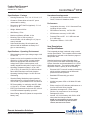
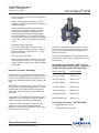
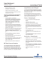
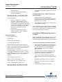
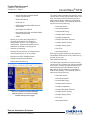
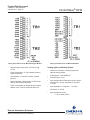
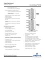
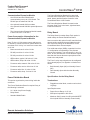
Product Data Document
1660DS-5i / D301290X012
October 2011 - Page 1
ControlWave® EFM
Standard Integrated Package
ControlWave® EFM, from Emerson Process Management, is intended for applications that require
combined electronic flow computer (EFM), process
control and remote terminal unit (RTU) functionality
in one integrated remote installation.
ControlWave EFM combines the capabilities of
an advanced RTU with the convenient “one box”
packaging of a highly-integrated flow computer.
Transducer assembly, solar/battery power system,
and communication devices can all be specified as
integrated components in the package.
Instead of expanding on a very limited chart replacement or flow computer, Emerson designed
our ControlWave Micro platform as the heart of
the package. Users will appreciate the processing
capabilities that allow ControlWave EFM to handle
all functions at sites, such as four-run M&R stations.
At the same time, power management minimizes
power consumption, and keeps battery and solar
panel costs under control.
Open card slots for communication or I/O distinguish this product and provide you with a great deal
of flexibility in matching up with installation requirements.
Using new, low-power electronics, the ControlWave
Micro Four-slot Chassis (as shown above) or
8-slot chassis is the heart of the ControlWave
EFM Standard Integrated Package (top).
ControlWave EFM is extremely effective in any of
the following capacities:
Monitoring and Control of an Entire Well Site, including the well head, meter, separator, compressor,
etc.
Artificial Lift and Production Optimization, e.g. Injection Control, Plunger Lift
Multiple-run M&R Station Automation—not only flow
measurement but also run switching, flow/pressure
control, control of odorizers and samplers, communication with a chromatograph, and communication
on multiple networks.
Remote Automation Solutions
Website: www.EmersonProcess.com/Remote
ControlWave EFM Overview
Hardware/Packaging Features
•
32-bit, ARM 9 processor provides exceptional
performance
•
Two processor selections are available: 33 MHz
ARM 9 minimizes power consumption or the
150 MHz ARM 9 includes Ethernet.
•
Multivariable transducer assembly is integrated
in the instrument package and allows quick
replacement as an independent component.
Product Data Document
1660DS-5i / D301290X012
October 2011 - Page 2
•
Very low power consumption minimizes costs
of solar/battery power systems, which are also
integrated in the package.
ControlWave® EFM
Application Areas
ControlWave EFM is appropriate to all applications
for combined flow computers, process controllers
and RTU products with prime examples as follows:
•
Three serial communication ports are standard.
•
Two or six open card slots for communication
and I/O expansion allow up to 10 serial ports or
96 I/O points.
•
Production wells
•
Injection wells
Mixed I/O cards provide cost effective I/O for
RTU applications using only one or two card
slots.
•
Production optimization applications
•
Off-shore platforms
Broad selection of modem and wireless
communications are instrument package
options.
•
Separation plants
•
Compressor stations
•
Storage facilities
•
Transmission metering stations
•
Distribution/LDC metering/gate stations
•
•
•
Integral 4-line LCD with 25-key keypad
(optional) allows operators to change
configurable parameters, on site, without
packing a PC.
•
Operating temperature range is -40 to 158ºF
(-40 to 70ºC).
•
CE Approved
Firmware/Software Features
•
ControlWave EFM is pre-programmed to meet
API 21.1 requirements for a four-run metering
station with networking via BSAP or Modbus.
•
Additional, standard application programs will
be introduced on a continual basis.
•
Using our ControlWave Designer, IEC 61131-3
programming environment, any user or third
party can modify the standard application or
create a completely customized program—and
full support from Emerson is available, every
step of the way.
•
PC web style menu pages are pre-configured
for all user operations
Remote Automation Solutions
Website: www.EmersonProcess.com/Remote
ControlWave EFM Standard
Integrated Package Overview
ControlWave EFM is delivered in a fiberglass enclosure that has provisions for not only the electronics but also a display/keypad, DP/P/T transducer
assembly, battery/solar power system and a broad
selection of modem and radio communications options.
Product Data Document
1660DS-5i / D301290X012
October 2011 - Page 3
ControlWave® EFM
Specifications – Package
Hazardous Area Approvals
•
Housing Dimensions: 14 ½” H x 12” W x 8 ½” D
•
•
Clearance: Please allow at least 2.5” space
underneath for cabling
•
Dimensions: MVT Wet End (optional): 3” H x 3
¾” W x 2 ½” D
•
Weight: Minimum 26 lbs
•
With Battery: 57 lbs
•
Maximum w/Battery & Radio: 61 lbs
•
Mounting: Pipe or wall-mounting is
recommended; a kit for affixing to a 2” pipe or
mast is included
•
Solar Panel Mounting: All solar panels are
delivered with all hardware necessary for 2”
pipe or mast-mounting
Specifications – Operating Environment
•
Wide operating power input voltage range of 4.9
to 16.0 Vdc
•
System can be set for operation as either 6 Vdc
nominal or 12 Vdc nominal—jumper settings
determine appropriate shut-down/start-up
voltage levels (Note: certain options, most
notably standard model radios, require 12 Vdc)
•
Operating Temperature Range: -40 to 158ºF
(-40 to 70ºC); de-rated 2ºC per 1000 feet when
above 6600 feet-above-sea-level elevation
•
Operating Humidity Range: 0 to 95% RH noncondensing
•
Vibration Rating: Maintains proper operation
while subjected to a 2.0g acceleration over 10150 Hz and 1.0g acceleration over 150-2000 Hz
UL approved Non-incendive for operation in
Class I, Division 2 Hazardous Areas
Performance
•
Computation Accuracy: 0.01% Corrected Flow,
including all input values
•
DP Reference accuracy: 0.075% URL
•
SP Reference accuracy: 0.035% URL
•
Pressure Effect on DP: 0.1% URL zero and
0.1% URL span
•
Temperature Effects: 0.21% URL
Item Descriptions
and Specifications
The integrated package is ordered using a model
number specification. The complete model number
specification is included on the last three pages of
this product data.
Standard equipment includes fiberglass housing, four-slot or 8-slot base chassis with CPU and
System Controller and the standard API 21.1 EFM
application program. The model number additionally allows a user to specify all of the following:
•
Emerson’s MVT “wet end” transducer assembly,
which provides measurement of differential
pressure and static pressure
•
Bendable RTD assembly, pre-wired
•
Thermowell
•
33 MHz low-power CPU or 150 MHz CPU with
Ethernet
•
RFI Susceptibility: In conformity with IEC 10004-3 (Level 2): 3V/meter - 80MHz to 1000MHz
•
•
ESD: Field connected circuits meet IEC 1000-42 for ESD withstand capability up to 4KV
Either a two-line LCD with two pushbuttons or a
four-line LCD with 25-key keypad
•
•
Nema Rating: Nema 3R (Nema 4x except with a
battery vent)
Hazardous area approval – either Class I
Division 2 by component or for the Integral
Package as a whole
•
Internal, 12V, 33 AH battery with 30W or 40W
solar panel and charger module.
NOTE: the internal battery and solar power
systems are available only with the 4-slot
chassis, NOT the 8-slot chassis.
Remote Automation Solutions
Website: www.EmersonProcess.com/Remote
Product Data Document
1660DS-5i / D301290X012
October 2011 - Page 4
A Guided Tour of the Standard
Integrated Package with Specifications
Remote Automation Solutions
Website: www.EmersonProcess.com/Remote
ControlWave® EFM
Product Data Document
1660DS-5i / D301290X012
October 2011 - Page 5
ControlWave® EFM
•
Comm expansion or I/O cards in slot 3 and slot
4 of the chassis
•
Choice of OEM modem and radio on comm
expansion module; these are tightly integrated,
embedded models.
•
Choice of standard radio that is installed on
a bracket in the Integral Package, not on the
comm expansion module; standard radios
are those that are commonly available from
Freewave and MDS. Due to space limitations
for wiring and connectors, the package is limited
to one radio, whether it is an OEM or standard
model.
•
Polyphaser surge suppressor
•
21 V dc/dc power supply—used to provide
power for analog loops, but is not necessary if
external loop power is provided or 4 – 20 mA
loops are not used
Emerson recommends that users practice “depot
level” service, in other words, that the MVT assembly be removed and replaced at the shop rather
than out at the site.
•
Discrete output relay board
•
Power distribution board—required if any of the
following are also ordered: 21 Vdc loop supply
module, Discrete output relay module, standard
model radio
Each MVT assembly has a nine-digit part number,
which can be used to specify a replacement part (a
listing follows).
Emerson’s Sensor Assembly
Using the MVT in the standard integrated package
is the easiest implementation for a single meter run;
however, the standard application program also allows use of external transmitters, with or without the
MVT.
Most multiple run systems use the MVT for the first
run and external, multivariable transmitters, such as
the 3808 MVT from Emerson (which includes the
exact same wet end assembly), for the additional
meter runs.
A key feature of ControlWave EFM is that the MVT
assembly can be removed and replaced, independently of all other components in the package.
If the MVT assembly requires a repair, you can
change it out and continue operating with the
electronics, including flow information, alarms and
historical archives, all intact.
Remote Automation Solutions
Website: www.EmersonProcess.com/Remote
Cross Reference Between “ABC” Code in
the Model Number and Emerson 9-Digit Part
Number for Replacement MVT Assembly
CODE DP/P URL
PART NUMBER
121150”/1000 psi
396531-01-6
122150”/2000 psi
396531-02-4
132100”/2000 psi
396531-04-0
141300”/1000 psi
396531-05-9
142300”/2000 psi
396531-06-7
2025psid/2000 psi
396531-07-5
20425psid/4000 psi
396531-09-1
Physical Specifications – MVT Assembly
•
Flange Material: 316 SS
•
Flange Bolt Material: 316 SS
Product Data Document
1660DS-5i / D301290X012
October 2011 - Page 6
ControlWave® EFM
•
Diaphragm Material: 316 SS
Integral Enclosure and LCD/Keypad
•
Fill Medium: DC 200 Silicone
•
Flange Process Connections: ¼” NPT
•
Connects to the System Controller card via a
dedicated SPI bus cable.
You can choose between two aspects of the enclosure: whether a four-slot or eight-slot ControlWave
Micro chassis is installed and which display/keypad
assembly is to be used.
Accuracy and Performance Specifications
– MVT Differential Pressure and Static
Pressure
•
Both display/keypad assemblies have identical, 4
line x 20 character liquid crystal displays and connect to the System Controller via a dedicated, CAT5
cable, which is delivered pre-wired.
Combined effects of nonlinearity,
nonrepeatability and hysteresis at reference
pressure and over the operating temperature
range: DP: ±0.075% of Calibrated Span or
0.015% of URL, whichever is greater. SP:
0.035% of calibrated span or 0.1% of URL,
whichever is greater.
Features – Display/Keypads
•
•
•
4 line by 20 character backlit liquid crystal
display
•
Adjustable display contrast
•
Membrane keys with tactile feedback
Temperature effect on Static and Differential
pressure: ±0.21%URL maximum combined shift
of zero and span with an ambient temperature
change of 60ºC (108ºF)
•
Self-adhesive overlay mounts to the enclosure
door or panel (Standard Integrated Package
is delivered with this assembly installed on the
door)
Static Pressure Effects On Differential Pressure:
Zero error: ±0.1% URL, for a change in static
pressure of 1000 psi; Span error: ±0.1%
reading, for a change in static pressure of 1000
psi
•
Easy configuration via ACCOL III Function Block
•
Scrolling display mode
•
Adjustable timer turns off display when not in
use
•
The standard application program works with
either display/keypad.
•
Long Term Stability at Constant Conditions:
±0.1% URL/Year typical
•
Mounting position effect: ±2 in H2O maximum,
which can be calibrated out.
•
Power Supply effect: ±0.005% of URL maximum
for any change within specified input power
supply voltage range.
•
Window size: 1.1” H x 3.1”W (2.8cm x 7.9cm)
•
Character size: 4mm H x 3mm W
Ripple and noise: Per ISA 50.1 Section 4.6
•
Dimensions: 2-button and 25-button versions
have the same footprint: 7.4”H x 5.5”W (18.8cm
x 14.4cm)
•
Power consumption: Local Display: 2.5 mA @
3.3V (0.008 watts); Remote Display/Keypad: 2.5
mA @ 3.3V (0.008 watts)
•
Operating Temperature: -4 to 158ºF (-20 to
70ºC)
•
MVT Static Pressure Orientation
You can specify whether the static pressure sensor is oriented to the right or to the left from the
point-of-view of a user looking at the front of the
ControlWave EFM. Following the AGA3-1992 convention, we refer to the static pressure sensor location as the “upstream” (a.k.a. “high side”) location.
Remote Automation Solutions
Website: www.EmersonProcess.com/Remote
Specifications – Display/Keypads
Product Data Document
1660DS-5i / D301290X012
October 2011 - Page 7
ControlWave® EFM
The 2-button display allows an operator to view
site, configuration and process data. The screens
are organized in a series of lists. The operator
can select a list and then manually scroll through
the data. Additionally, a “scroll list” can be defined.
The ControlWave EFM can be set to automatically
sequence through this list.
The 25-button Display/Keypad performs the same
functions and additionally allows the operator to
view and modify ControlWave EFM inputs, process
variables, calculated variables, setpoints, tuning
parameters, and outputs used in a measurement
Please remember that dedicated interfaces for
the MVT Wet End, RTD and LCD/ Keypad are all
located on the System Controller. You need not
allocate serial communication ports for any of these
devices!
Specifications for CPU and
System Controller
CPU
or control application. Status bits include the alarm
state, alarm acknowledge, control, and manual
(Auto/Man). Providing access to such variable
information allows you complete control over the
process operation.
ControlWave Micro Chassis, CPU
and 5 - 16 V System Controller
You can choose all combinations of the following:
•
4-slot or 8-slot CW Micro Chassis
•
33 MHz low-power CPU or 150 MHz CPU that
includes Ethernet and larger memory module
Note: Internal battery and solar power options are
not available with the 8-slot chassis.
Remote Automation Solutions
Website: www.EmersonProcess.com/Remote
•
32-bit ARM 9 processor with 33 MHz or 150
MHz clock rate
•
Sleep mode for low-power applications
•
The 150 MHz CPU also includes a keylock
security switch
•
Memory Models
33 MHz CPU
• Program Execution and Data Memory:
2 MB SRAM battery backed memory
• File and Historical Archive Memory: 8
MB on-board flash
150 MHz CPU
• Program Execution: 64 MB SD RAM
• Data Memory: 2 MB SRAM battery
Product Data Document
1660DS-5i / D301290X012
October 2011 - Page 8
backed memory
• File and Historical Archive Memory: 16 MB on-board flash
•
LED status indicators – 6 failure status LEDs,
Watchdog and Idle and communication LEDs
•
Power consumption:
• Chassis, 33 MHz CPU + System
Controller + MVT Assembly + LCD/
keypad: 7.2 mA at 12 Vdc minimum but
varies based on the application program
requirements. Assembly + LDC/Keypad:
7.2 mA at 12 Vdc minimum but varies
based on the application program
requirements.
• Chassis, 150 MHz Ethernet CPU +
System Controller + MVT Assembly +
LCD/Keypad: 102 mA.
System Controller
ControlWave® EFM
•
Terminations: Pluggable, maximum wire size is
16 gauge
Communication Ports – Base (Located on
the CPU Card)
•
Two RS-232 and one RS-485 serial
communication ports with standard 9-pin male
D-sub connectors on CPU module, supporting
baud rates up to 115.2 KB
•
10/100 Ethernet Interface on the 150 MHz CPU
using an RJ45 connector
Note: Additional communication ports are available
on the Comm Expansion Module, which is installed
in an I/O slot. Please refer to the discussion on I/O
Slots 3 and 4 for further information.
ControlWave EFM Standard Application
Program
•
LCD/Keypad interface
•
RTD Interface
•
LEDs for idle and watchdog
•
6 run-time diagnostic LEDs
Overview of the standard application program:
•
Power-fail detection and recovery sequencer
•
•
4.9 to 16 Vdc power input can be configured via
jumper (for shutdown sequencing purposes) as
nominal 6 Vdc or 12 Vdc input.
Uses pre-configured web-style menu pages for
user readings, configuration and maintenance—
PC menu pages can be modified and new
pages configured to work with a modified
application load
•
Operating Range: +4.5/4.9 V to +16.0 V (+6 V
Input Supply) (Shutdown occurs at +4.72/4.33
V nominal); +9.6/10.3 V to +16.0 V (+12 V Input
Supply) (Shutdown occurs at +10.29/9.56 V
nominal)
•
Uses the TechView Utility for calibration of all
transducers, including the integral MVT and
external transmitters (e.g. 3808 MVT)
•
The PC menu pages, calibration utility and
program load are all included on the BSI Config
CD.
The ControlWave EFM is shipped with the 1 – 4 run
M&R load program (.pro file) loaded in Flash and
the Flash Configuration Program (FCP) also loaded.
•
Output Voltage: +3.3 Vdc ±1%
•
Output Current: 1 A Max. @ 3.3 Vdc
•
Standard configuration is a four-run station
•
Output Ripple P/P: +3.3 V Output: 10 mV
•
•
Fusing: 1 A Slow Blow 5x20 mm fuse
Each run can be orifice, turbine or ultrasonic
meter type
•
Surge Suppression: 16 V Transorb to DGND
and Chassis Meets ANSI/IEEE C37.90-1978
•
Flow calculations include the following:
Remote Automation Solutions
Website: www.EmersonProcess.com/Remote
Product Data Document
1660DS-5i / D301290X012
October 2011 - Page 9
ControlWave® EFM
• AGA3-1992 with selectable AGA8
Gross or AGA8 Detail
The Hourly Data Log holds one record for every
contract hour. Hourly logs hold 840 entries or 35
days; this ensures that the previous period of
hourly data is always resident in ControlWave
EFM FLASH memory. The following items are
stored in the Hourly Data Log:
• AGA3-1985/NX-19
• AGA7/NX-19
• AGA7 with selectable AGA8 Gross or
AGA8 Detail
•
• Corrected Volume
• Auto Adjust AGA7/NX-19
• Uncorrected Volume
• Auto Adjust AGA7 with selectable AGA8
Gross or AGA8 Detail
• Accumulated Energy
• AGA9
• Average Temperature
• Average Static Pressure
Allows you to select the integral MVT or
an external transmitter for a single run
configuration or as run 1 in a multiple run
configuration. External transmitters can be
interfaced via RS 485 or analog inputs.
• Average Differential Pressure
•
Includes run switching
• Flow Time
•
Includes an auto-selector, PID flow/pressure
control algorithm per run or per station
• Uncorrected Count
•
Resides on a BSAP SCADA network
•
Supports samplers and odorizers
•
Hourly Historical Data Log
• Average Specific Gravity
• Average Heating Value
Each log entry also contains the date and time.
ControlWave EFM has an Hourly Historical Log
for each of four runs.
•
Daily Historical Data Log
The Daily Data Log holds one record for every
contract day. The contract hour may be changed
by the user. The daily log holds 62 entries; this
ensures that the previous calendar month of
daily data is always resident in ControlWave
EFM FLASH memory. The following items are
stored in the Daily Data Log:
• Corrected Volume
• Uncorrected Volume
• Accumulated Energy
• Average Static Pressure
• Average Temperature
• Average Differential Pressure
The user’s interface to the Standard Application Program is via a series of straightforward web style menu pages.
• Average Specific Gravity
• Average Heating Value
• Flow Time
• Uncorrected Count
Remote Automation Solutions
Website: www.EmersonProcess.com/Remote
Product Data Document
1660DS-5i / D301290X012
October 2011 - Page 10
ControlWave® EFM
Each log entry also contains the date and time.
ControlWave EFM has a Daily Historical Log for
each of four runs.
•
Periodic Historical Data Log
The periodic data log holds one record for every
log interval. Log interval is 15 minutes. The
Periodic Historical Data Log holds 1440 records,
or four days of 15 minute data. The following
items are stored in the Periodic Historical Data
Log:
• Flowing Differential Pressure
• Flowing Static Pressure
• Flowing Temperature
• Frequency
Each log entry also contains the date and time.
ControlWave EFM has a Periodic Historical
Data Log for each of four runs.
•
Audit Trail Alarm and Event Storage
ControlWave EFM keeps an Audit Trail Buffer
capable of storing the most recent 500 Alarms
and the most recent 500 Events. Internally,
these buffers are maintained separately to
prevent recurring alarms from overwriting
configuration audit data. Externally, they are
reported to the user as a single entity. Both
operate in a circular fashion with new entries
overwriting the oldest entry when the buffer
is full. The following circumstances cause an
entry to be made in the Audit Trail Buffer:
•
Any operator change to a ControlWave EFM
configuration variable
•
Any change in the state of a ControlWave
EFM alarm signal
•
A system restart
•
Certain other system events
•
Includes a nominations function
•
Allows you to select engineering units from a
broad variety, including English and metric
•
Interfaces to a chromatograph and provides
Remote Automation Solutions
Website: www.EmersonProcess.com/Remote
energy throughput as well as composition
information. Requires a Comm Expansion
Module so that port COM4 could connect to the
chromatograph.
•
Self Diagnostics
ControlWave EFM periodically runs a series of
diagnostics to verify the operational status of
various system components. The tests include
transducer parameters, main and backup
battery voltages, software sanity checks,
and other indications of system health. An
appropriate alarm is generated if any test fails.
Communication Port Configuration for the
Standard Application Program
COM1 – Local RS 232 port for configuration via a
PC. Flash configuration is BSAP Slave, 115.2K
baud rate. The PC port connector, that is accessible, externally, on the bottom of the Standard
Integrated Package, is connected to this port on the
ControlWave Micro CPU.
COM2 – RS 232 Network port with Flash configuration of BSAP Slave, 9600 baud. The standard
application program is compatible with an external communication device or standard radio. If a
standard radio is included, the Standard Integrated
Package will also include a cable that connects this
port, on the ControlWave Micro CPU, to the RS 232
port on the radio.
Notes on other Network Options: If an OEM radio
or modem is to be used for networking, ports on the
Comm Expansion Module would be allocated. If the
Comm Expansion Module is in slot 3, COM6 is used
for the radio and COM7 is used for the modem. A
Comm Expansion Module in slot 4 will use COM10
for the radio and COM11 for the modem. Use of
the OEM modem or radio requires a change to the
standard application program as well as to the Flash
Configuration for compatibility.
COM3 – RS 485 port with Flash configuration of
BSAP Master at 9600 baud. The standard application program assumes that 3808 MVT multivariable
transmitters for meter run measurement are to be
interfaced to this port.
Product Data Document
1660DS-5i / D301290X012
October 2011 - Page 11
COM4 – NOTE THAT THIS PORT IS ON THE
OPTIONAL, COMM EXPANSION MODULE – RS
232 port with Flash configuration of Modbus (ASCII)
Master at 9600 baud. The standard application program assumes that this port will be used to interface
to a chromatograph. Allocation of COM4 assumes
that the Comm Expansion Module is in Slot 3. If it’s
installed in Slot 4, the corresponding port is COM8
and the Flash Configuration must be changed to
reflect that.
COM5 – NOTE THAT THIS PORT IS ON THE
OPTIONAL, COMM EXPANSION MODULE –RS
485 port with Flash configuration of Modbus (RTU)
Master at 9600 baud. The standard application
program assumes that this port will be used to
interface with multivariable transmitters, such as the
3808 MVT, using the Modbus protocol. Allocation of
COM5 assumes that the Comm Expansion Module
is in Slot 3. If it’s installed in Slot 4, the corresponding port is COM9 and the Flash Configuration must
be changed to reflect that.
Ports COM6 and up – Please note that these ports
are not configured in FLASH or in the standard application program. As explained in the descriptions
for the other ports, Flash Configuration and, in some
cases, a change to the standard application program, are required to use these ports.
Power System
You can specify the solar/battery power system.
For most applications, the 33 Ampere-hour (AH)
battery, that is internal to the Standard Integrated
Packaged, can be matched with either a 30 watt or
40 watt, 2” mast-mounting solar panel.
Note that the internal battery and solar panel options are not available if the 8-slot chassis is used.
An external power source must be used.
For power loading details, please refer to the Emerson product data sheet entitled, ControlWave EFM
Power System Sizing (1660AD4, D301327X012).
Other “red flags,” which may tell you to specify a
larger, external battery include the 150 MHz Ethernet CPU, multiple analog loops that operate from
Remote Automation Solutions
Website: www.EmersonProcess.com/Remote
ControlWave® EFM
the 21 V dc/dc power supply rather than 12 V and
operation of a standard model radio with power
constantly on rather than duty cycling.
The 40 watt panel may need to be selected for
locations, which receive less than 2 sun-hours per
day. Again, the Power System Sizing data sheet
provides further information.
A charge regulator is always included with the solar
panel. This component is shipped with the panel
and must be installed inside a compartment on the
back of the panel.
A peculiarity in selection of the power system is that
the BP solar panels are FM approved for operation
in Class I, Division 2 areas while the ControlWave
EFM Standard Integrated Package, including the
internal battery, is approved for the same by UL.
Therefore, a UL-approved Standard Integrated
Package is ordered by specifying the battery but
without the solar panel. The solar panel is then
specified by part number.
If the solar panel is included in the model number,
hazardous area approval is only available at the
component level. Please refer to the description of
HAZARDOUS AREA CERTIFICATION, that follows.
Please also refer to the Emerson Process Management web site, www.EmersonProcess.com/Remote,
for data sheets on the following components in the
power system:
• 33 AH Battery
• 30 Watt Solar Panel
• 40 Watt Solar Panel
Hazardous Area Certification
If Class I, Division 2 certification is chosen, the
Standard Integrated Package is approved by UL
as an instrument. Note that this certification strictly
prohibits installation of any other hardware, not
indicated by the model number, in the instrument
enclosure. Wiring to and from the I/O, communication and power connections inside the enclosure,
per the ControlWave EFM manual, are, of course,
allowed.
Product Data Document
1660DS-5i / D301290X012
October 2011 - Page 12
Even without certification of the instrument by model
number, all the components have been UL approved for installation in Class I, Division 2 hazardous areas (except the solar panels, which are FM
approved). Selecting certification by component
level only allows you to install other hardware, such
as a ControlWave Micro I/O card that is not in the
model number specification, without the worry of
violating the certification.
A Class I Division 2 Non-incendive hazardous area
approval for the package as well as Industry Canada approval is also available. Note that the latter is
a metrological approval for custody transfer installations. The Industry Canada version of ControlWave
EFM differs from all other versions in a few areas:
ControlWave® EFM
The bendable RTD is a “one size fits all” solution
that is perfect for most applications and excellent for
depot-level inventory situations in which the ultimate
installation (and, therefore, the thermowell depth) is
not necessarily known.
The 12” probe can quickly be inserted in a thermowell, whereupon you can tighten the included fitting
to lock it in place and bend the excess length out of
the way.
Note that a thermowell is always required for this
bendable RTD
If the RTD cable assembly is ordered with the model, it is
shipped, “pre-installed” to the Standard Integrated Package.
•
An external connector for a PC cable will not be
included. A blank filler plate is installed, instead.
RTD Interface Information
•
To access a PC connector, you must open the
front door. Using the clasp that is available in
all models, installations are expected to use a
security wire to lock the front door. The seal
would need to be broken in order to open the
door.
A three-wire platinum RTD per DIN 43760 is supported. The temperature, T, in degrees Celsius is
calculated using the Resistance vs. Temperature
Tables according to the DIN EN 60751 standard for
Class A & B RTDs. The DIN EN 60751 equation is:
•
The data plate is different in a number of
line items in order to satisfy Industry Canada
requirements.
Furthermore, Industry Canada approval applies to
a specific model configuration. The entire model
number must be as follows:
CWM-EFM-2-142-121-02-32100-07-02-00-00-0000-1000-000
Bendable RTD
You can choose a bendable RTD that is attached
to the ControlWave EFM via an armored cable of
6-foot, 15-foot or 25-foot length. The individual
wires attach to a terminal block on the System Controller card.
Normally, this RTD would be used to provide the
process temperature input but the standard application program also allows you to select an external
temperature transmitter, instead.
Remote Automation Solutions
Website: www.EmersonProcess.com/Remote
R(t) = R0 * (1 + At +Bt2)
Where:
A = 3.9083 * 10-3 oC-1
B = -5.775 * 10-7 oC-2
Ro = 100ohms
In addition, you may enter the Ro, A, and B coefficients of a custom calibrated RTD, another platinum
standard or a different material (Nickel, Balco or
Copper).
During the RTD calibration, you are able to set the
coefficients, restore the factory default for these
coefficients, and calibrate the internal Reference
resistor.
RTD Input Specifications
These specifications are for the interface, only, not
including the RTD probe or wiring (please note that
RTD probe interchangeability can add ±0.7°C of
uncertainty to the measurement).
•
RTD Conversion Accuracy: ± 0.1°C, or ± 0.1%
of reading, whichever is greater
Product Data Document
1660DS-5i / D301290X012
October 2011 - Page 13
ControlWave® EFM
and 3808 MVT will operate using nominal 6 Vdc and
9 Vdc power sources.
The 21 V dc/dc Power Supply is not necessary if
loop power is otherwise available or if there are no
analog I/O points.
This option is a circuit board that is located on a
Snap Track, which is installed onto the back panel
in the lower, right-hand section of the Standard Integrated Package.
•
Ambient temperature effect on RTD
measurement: ±0.01°C / ºC max
•
Long Term Stability at Constant Conditions:
±0.25ºC / month max
Note that the Power Distribution Board is required
if the 21 V dc/dc Power Supply is selected. This is
another Snap Track option that is located nearby
the 21 V dc/dc Power Supply.
Specifications for 21 V dc/dc Power Supply
•
Input voltage: 10.8 to 16.0 Vdc
•
Input current: Will be double the current draw of
the output device, e.g. 100 mA typical at 12 Vdc
with a 50 mA load on the output; 140 mA max
over temperature range with a 50 mA output
load.
•
Output voltage: 21.4 Vdc ±0.8 Vdc
•
Output Current: 50 mA max
21 V DC/DC Power Supply
•
Ripple/Noise: 20 mV max P-to-P
Since the Mixed I/O cards (please refer to the next
section) available in ControlWave EFM do not
include loop power, this option provides power if 4
– 20 mA loops are to be used or if transmitters that
require a voltage that is higher than the nominal, 12
Vdc supply voltage are to be powered.
•
Efficiency: 88% typical
•
Fuses: F1=500 mA (slow blow) protects host
power source; F2=350mA (fast blow) protects
21 V dc/dc Power Supply from short circuits on
the output.
This option converts the nominal, 12 Vdc input to
21.4 Vdc for field devices such as transmitters.
Please note that, since the minimum input voltage
for this option is 10.8 Vdc, it will not work with nominal 6 Vdc or 9 Vdc power sources.
I/O Card Slots
Thermowell Options For RTD
For new installations, or those lacking a thermowell,
you can choose one of three lengths of thermowell
for the RTD.
While the 21 V dc/dc Power Supply is required for
use with a 3508 transmitter, it is not necessary to
provide power to our 2808 or 3808 MVT models.
For those, we recommend that system power be
routed to the transmitter. The Power Distribution
Board is a good way to provide power routing to
either of those transmitters. Furthermore, the 2808
Remote Automation Solutions
Website: www.EmersonProcess.com/Remote
These slots are open for you to select any combination of I/O modules can be used in slots 3 and 4.
For the Standard Integrated Package, we have
provided, in the model number specification, an assortment of modules we consider most appropriate
to gas measurement applications and remote sites.
However, any ControlWave Micro I/O modules can
be installed.
Product Data Document
1660DS-5i / D301290X012
October 2011 - Page 14
ControlWave® EFM
Important Hazardous Area Certification Note:
Specifications
If modules that are not listed in the model number
are installed, certification will only be allowed at the
component level.
All I/O
If the Standard Integrated Package is approved by
instrument model number, installing such modules
will violate that approval.
Standard Application Program – Use of I/O
Card Slots
Although the standard application program does not
necessarily require any I/O slots to be occupied,
it has been written to support a Comm Expansion
Module in slot 3 and a Mixed I/O Module (6 DIO, 4
AI, 2 HSC and with or without 1 AO) in slot 4. Use
of ports 4 and 5 on the Comm Expansion Module
and any of the I/O points are configurable by the
user via PC menu pages.
•
Surge protection meets C37.90-1978 and IEC
801-5
•
Terminations are pluggable and accept a
maximum wire size of 14 gauge
•
Power consumption is stated for each I/O
module measured at the 3.3 Vdc input supply
(for an equivalent at 12 Vdc that considers
efficiency, divide the stated figure by 3) and
does not include loop power.
Mixed Digital Input/Output Module
•
Number of points: 12 non-interrupting inputs
and 4 outputs
•
Input Voltage Range: Internally sourced dry
contact input: 3.3 Vdc
ControlWave EFM I/O – Features
•
On state: >1.5 V, Off state: <1.5 V
•
Convenient pluggable local wiring terminations
simplify installation.
•
Input current : selectable 66 µA for low-power
applications or 2 mA for in-plant noise immunity
•
Mixed AI/AO, DI/DO and AI/DI/HSC/AO/ DO
modules are very cost effective and reduce
board count for low I/O applications.
•
Digital outputs: Open drain. 100 mA max @
31 Vdc.
•
Sleep mode operation conserves power
(Electronics are not operating while I/O Clock
is off while I/O is in sleep mode; however, loop
power remains active).
•
Surge suppression: 31 Vdc transorb between
signal and ground meets ANSI/IEEE C37.901978
•
Input filtering: 15 ms time constant (contact
bounce)
•
Status indication: Optional plug-on LED board
with per point status indicators
•
Power consumption: Includes DOs
•
Low-power loop current operations are also
available to conserve power.
•
Any module can plug into either slot.
•
Terminal and wire covers neatly dress wiring
and protect connections.
•
Note that remote termination I/O modules
are also available for use with the CW Micro
chassis, although they are not included in the
ControlWave EFM model number.
•
Optional isolated ControlWave Micro I/O is
available (but not in the model number).
Remote Automation Solutions
Website: www.EmersonProcess.com/Remote
Status LEDs Disabled
1.3 mA @ 3.3 Vdc: 12 DIs OFF, CLK stopped
2.1 mA @ 3.3 Vdc: 12 DIs ON @ 66 uA, CLK
stopped
25.3 mA @ 3.3 Vdc: 12 DIs ON @ 2 mA, CLK
stopped
Product Data Document
1660DS-5i / D301290X012
October 2011 - Page 15
ControlWave® EFM
External Power V to I (AI/AO at 5 V @ 5 mA):
9.2mA
3.6 mA @ 3.3 Vdc: 12 DIs OFF, CLK active
4.4 mA @ 3.3 Vdc: 12 DIs ON @ 66 uA, CLK active
27.6 mA @ 3.3 Vdc: 12 DIs ON @ 2 mA, CLK active
Status LEDs Enabled
All DIs and DOs OFF: 33 uA @ 3.3 Vdc
High Speed Counter Module
•
Number of points: 4
•
Frequency Range: 0-10 kHz
•
Input Voltage Range:
All DIs and DOs ON: add 32 mA @ 3.3 Vdc
Internally sourced: 3.3 Vdc dry contact
Note: Specifications are at 3.3 Vdc; for a 12 Vdc
equivalent, divide by 3.
•
On state: >1.5 V, Off state: <1.5V
•
Debounce: Yes (selectable)
Mixed Analog Input/Output Module
•
Input current : selectable 200 µA for low-power
applications or 2 mA for in-plant noise immunity
•
Surge Suppression: 31 Vdc transorb between
signal and ground meets ANSI/IEEE C37.901978
•
Power consumption at 3.3 Vdc (divide by 3 to
obtain equivalent at 12 Vdc):
3.9 mA CLK stopped (All Inputs OFF)
6.8 mA CLK running (All Inputs OFF)
•
Number of Channels: 6 AI or 6 AI/2 AO
•
AI Resolution: 14-bit SAR ADC
•
AO Resolution: 12-bit
•
Input Configuration:Externally sourced. Single–
ended inputs - jumper selectable 4–20 mA or
1–5 Vdc
•
Input Impedance: 1 megOhm - 1 to 5 Vdc;
250 Ohms - 4–20 mA
•
Input & output accuracy:
Additional Current per Input
200uA or 2mA per HSCSET or HSCRST Input
(ON State)
2mA per ON LED
33uA for LED circuitry
• 0.1% of span at 25oC
• 0.2% of span -40oC to 70oC
• 0.3% of span -40oC to 70oC (AO only)
•
Surge suppression: 31 Vdc transorb between
signal and ground meets ANSI/IEEE C37.901978
•
Output configuration: Externally sourced
4-20 mA: 650 W for 24 Vdc source
1-5 Vdc: 5 mA max., 11 to 30 Vdc external
source
•
Power consumption:
5.0 mA at 3.3Vdc for the module
External Power V to I (AI/AO at 20mA each):
24.3mA
External Power V to I (AI/AO at 5V @ 0mA):
4.2mA
Remote Automation Solutions
Website: www.EmersonProcess.com/Remote
Mixed I/O Module
Number of points: 4 AI, 1 AO (optional), 6 DI/DO, 2
High Speed Counter Inputs
Base power consumption: 5 mA at 3.3 Vdc
Digital Inputs and Outputs
•
Number of points: 6 non-interrupting inputs or
dry contact outputs
•
Input Voltage Range: Internally sourced dry
contact input: 3.3 Vdc
•
On state: >1.5 V, Off state: <1.5V
•
Input current : selectable 66 µA for low-power
applications or 2 mA for in-plant noise immunity
Product Data Document
1660DS-5i / D301290X012
October 2011 - Page 16
ControlWave® EFM
Wiring Terminations for the Mixed I/O Module
Wiring Terminations for the Mixed Analog I/O Module
•
Digital outputs: Open drain. 100 mA max @
31 Vdc
•
Surge suppression: 31 Vdc transorb between
signal and gound
•
Input filtering: 15 ms time constant (contact
bounce)
•
Status indication: Optional plug-on LED board
with per point status indicators
•
Power consumption for Digital Inputs/ Outputs:
add 66 mA or 2 mA for each point that is on.
Analog Inputs and Analog Output
•
Number of Channels: 4 Analog Inputs and 1
optional Analog Output
•
AI Resolution: 14-bit SAR ADC
•
AO Resolution: 12-bit
•
Input Configuration:Externally sourced. Single–
ended inputs - jumper selectable 4–20 mA or
1–5 Vdc
•
Input Impedance: 1 megOhm - 1 to 5 Vdc;
250 Ohms - 4-20 mA
•
Input & output accuracy:
• 0.1% of span at 25oC
Remote Automation Solutions
Website: www.EmersonProcess.com/Remote
Product Data Document
1660DS-5i / D301290X012
October 2011 - Page 17
ControlWave® EFM
• 0.2% of span -40oC to 7oC
• 0.3% of span -40oC to 7oC (AO only)
•
Output configuration: Externally sourced
• 4-20 mA: 650 Ohms for 24 Vdc source
• 1-5 Vdc: 5 mA max., 11 to 30 Vdc
external source
•
Surge Suppression: 30 Vdc transorb between
signal and ground
•
Power consumption:
External Power V to I (AI/AO at 20 mA each):
24.3 mA
External Power V to I (AI/AO at 5 V @ 0 mA):
4.2 mA
External Power V to I (AI/AO at 5 V @ 5 mA):
9.2 mA
High Speed Counter Inputs
•
Number of points: 2
•
Frequency Range: 0-10 kHz
•
Input Voltage Range:
Wiring Terminations for the High
Speed Counter Module
Internally sourced: 3.3 Vdc
•
Externally sourced: 3 Vdc to 24 Vdc
•
On state: >1.5 V, Off state: <1.5V
•
D / A resolution:
•
Debounce: Yes
•
•
Input current : selectable 175 mA for low-power
applications or 2 mA for in-plant noise immunity
•
Accumulator: 16-bit
Accuracy:
0.1% of span @ 25oC for current output;
0.1% +6% of span @ 25oC for voltage
0.3% of span @ -40 oC to 70 oC for current
0.3% +6% of span @ -40 oC to 70 oC for voltage
•
Surge Suppression: 31 Vdc transorb between
signal and ground
•
Electrical Isolation: 500 Vdc channel to bus
•
Power consumption:
•
Settling time: 50 microsecond
•
Surge Suppression: 16 Vdc transorb across
output signals and (-) output to common
•
Power consumption - 4 inputs:
200 uA or 2 mA per Input on state
Isolated Analog Output Module
•
Number of Channels: 4
•
Output Configurations: 4–20 mA (650 max.
Remote Automation Solutions
Website: www.EmersonProcess.com/Remote
drive) and 1–5 Vdc @ 5 mA max.
12-bit
Analog current output: 3.0 watt
Analog voltage output: 1.3 watt
Product Data Document
1660DS-5i / D301290X012
October 2011 - Page 18
Communication Expansion Module
•
One RS 232 and one RS 485 serial
communication port up to 115.2 Kbaud. The
RS-485 port is isolated to 500 Vdc
•
One optional internal dial-line modem
•
One optional internal 900 MHz spread Spectrum
radio
•
The Communication Expansion Module installs
in either I/O slot 3 or I/O slot 4.
Power Consumption Information for the
Communication Expansion Module
Note: To size a 12 Vdc power system and account
for efficiency in dc/dc conversion, please divide current draw at 3.3 Vdc by 3 to convert to current draw
at 12 Vdc.
ControlWave® EFM
The Power Distribution Board will be pre-wired
to all the above-listed items, as well as the solar
panel, battery and the System Controller in the
ControlWave Micro 4-slot Chassis.
The Power Distribution Board is located on the
left-most Snap Track in the lower, right-hand area,
inside the enclosure.
Relay Board
The Relay Board is another Snap Track option located nearby the Power Distribution Board.
Users can select this option if on/off control devices
operate under conditions that are higher than the
100 mA/35 Vdc ratings of the MOSFETS on the
ControlWave Micro discrete outputs.
Four solid state relays (SSRs), organized in a form
‘C’ configuration corresponding to two discrete
outputs, are included. You must specify, in slot 3 or
slot 4, an I/O card with two or more discrete outputs.
Note that the first two discrete output points will be
wired to the relay board.
•
Base current draw: 6 mA at 3.3 Vdc
•
RS 485 port driver: 3 mA at 3.3 Vdc
•
RS 232 port driver: 6 mA at 3.3 Vdc
•
OEM modem, typical: 180 mA at 3.3 Vdc
•
OEM modem, sleep: 88 mA at 3.3 Vdc
•
Freewave radio, transmit: 500 mA at 12 Vdc
The Form C relay output signals can be configured
via on-board jumpers, for opposite or identical conditions:
•
Freewave radio, receive: 86 mA at 12 Vdc
•
•
Freewave radio, idle: 21 mA at 12 Vdc
Both Normally Open (NO) or Normally Closed
(NC)
•
Freewave radio, sleep: 5 mA at 12 Vdc
•
One Normally Open with the other Normally
Closed
Power Distribution Board
Specifications for the Relay Board
This option organizes the power wiring inside the
enclosure.
Terminations
The Power Distribution Board is required if any of
the following is selected:
•
21 V dc/dc Loop Power Supply
•
Relay Board
•
Standard Model Radio
Remote Automation Solutions
Website: www.EmersonProcess.com/Remote
•
Pluggable terminal block, maximum wire size is
14 gauge
Input Requirements
•
Power Source Range: 3-15 Vdc
•
SSR Input Impedance: 400 Ohms
•
Maximum Sink Current from DO point MOSFET:
20 mA (both SSRs in Normally Closed mode)
Product Data Document
1660DS-5i / D301290X012
October 2011 - Page 19
•
Minimum Current Load: 100 mA
Output Requirements
•
Contact Ratings: 3-60 Vdc
•
Maximum Current: 3 Amps @ 25°C or 1.5
Amps @ 70°C
If the Relay Board is selected, the Power Distribution Board is required and connections between the
two will be pre-wired.
Switched Network Modem
You can specify whether any modems are included.
Physically, an OEM modem chip is installed on a
Comm Expansion Module, which is located in I/O
slot 3 or 4. Naturally, the Comm Expansion Module must also be specified and, if two modems are
specified, two Comm Expansion Modules must also
be included.
If two Comm Expansion Modules are specified but
only one modem is specified, the modem will be
installed on the Comm Expansion Module in I/O
slot 3. Please remember that a Comm Expansion
Module can include both an OEM modem and OEM
radio.
Please keep in mind that the modem cannot be
added after shipment if UL approval is by instrument
model number (but can be if approval is at the component level, only). In any case, we strongly urge
users to order the modem in the model number so it
is installed at the factory before shipment.
For addition, later, or replacement purposes, the
modem kit part number is 396582-03-6.
Power consumption specifications for the modem
are listed under the description of the Communication Expansion Module (prior page).
Polyphaser Option For Radio
If a radio is specified, you can select whether or not
a Polyphaser surge protector will also be included.
Emerson always recommends the Polyphaser.
Remote Automation Solutions
Website: www.EmersonProcess.com/Remote
ControlWave® EFM
Radio Option
Due mainly to space constraints for connections on
the bottom panel, the Standard Integrated Package
is limited to one radio.
The embedded OEM radio and standard model
radios are available.
Embedded OEM radios are tightly-coupled spread
spectrum models, which, like the modem, are
installed on the Comm Expansion Module. If two
Comm Expansion Modules are selected, the OEM
radio will be installed on the one in I/O slot 3. Note
that a modem and radio can coexist on the same
Comm Expansion Module.
Like the modem, the OEM radio can be added, later,
to the Comm Expansion Module, only if hazardous
area approval at the component level, and not by
instrument model number, is selected. However, we
always strongly urge users to order the radio in the
model number so it is installed at the factory before
shipment.
In any event, radio kits are available and can be
ordered by part numbers as follows:
•
Freewave Radio Kit – 396582-02-8
Standard radios are popular models offered by
Freewave and MDS. A broad selection is available.
Since some users prefer to procure the radios,
separately, Emerson offers “radio ready” configurations for each of the standard models. Radio-ready
models include literally everything except for the radio. The mounting bracket as well as all cables and
connections are in place. The user or integrator/installer must simply mount the radio to the bracket
and make connections.
It is important to match the radio ready configuration
with the specific radio you expect to install because
cables and connections for the antenna, RS 232
port and power all vary by radio model!
For specifications on the radios, please refer to the
Emerson Process Management web site,
www.EmersonProcess.com/Remote, where individual data sheets are available in pdf format.
Product Data Document
1660DS-5i / D301290X012
October 2011 - Page 20
Power Consumption Information for
Standard Radios
For OEM radio power consumption, please refer to
the description of the Communication Expansion
Module.
Freewave FGR Spread Spectrum Radio Figures at
12 Vdc:
•
Receive: 75 mA
•
Transmit: 500 mA
•
Idle: 20 mA
•
Sleep: 5 mA
MDS TransNet 900 Spread Spectrum Radio Figures
at 13.8 Vdc:
•
Receive: 115 mA
•
Transmit: 510 mA
•
Sleep: 8 mA
MDS models 4710 and 9710 Licensed, UHF Radios
with figures at 13.8 Vdc:
•
Receive: 125 mA
•
Transmit: 2000 mA
•
Sleep: 15 mA
MDS entraNet 900 IP Radio Figures at 13.8 Vdc:
ControlWave® EFM
The DB-9 cables are null modem, 9-pin female-to9-pin female, which match up to the weatherproof
hood assembly on the bottom of the ControlWave
EFM enclosure.
10-foot Cable – p/n 396647-01-4
25-foot Cable – p/n 396647-02-2
TeleFlow Cable
The TeleFlow cables match up to the circular, Alden
connector, which is now shipping with ControlWave
EFM products.
10-foot Cable – p/n 395402-01-8
25-foot Cable – p/n 395402-02-6
TeleFlow Cable Adapter
An adapter is available to match up the TeleFlow
PC cable so it can be used with the DB-9 connector, which was originally used on ControlWave EFM.
Users can plug the circular connector, on the existing cable, to the adapter, which, in turn, plugs into
the DB-9 connector inside the weatherproof hood
on the bottom of the ControlWave EFM enclosure.
Adapter – p/n 395694-01-9
Standard Application Program and PC Menu
Pages
MDS iNet 900 Ethernet/IP Radio Figures at
13.8 Vdc:
ControlWave EFM comes pre-loaded with the Standard Application Program (.pro file) in Flash. However, the PC menu pages are not loaded in Flash
but are available either via the Emerson Process
Management web site or on a CD. The CD is the
“BSI Config” CD, which also contains the LocalView
Calibration Tool as well as a copy of the Standard
Application Program.
•
Receive: 203 mA
BSI Config CD – p/n 395575-02-8
•
Transmit: 580 mA
•
Receive: 100 mA
•
Transmit: 510 mA
•
Sleep: 7 mA
Accessories
DB-9 Cable
Remote Automation Solutions
Website: www.EmersonProcess.com/Remote
For users wishing to modify the Standard Application Program, it is available as source code. Please
contact Emerson’s Remote Automation Solutions
Application Services department for information.
Product Data Document
1660DS-5i / D301290X012
October 2011 - Page 21
ControlWave® EFM
Product Family Compatibility
ControlWave EFM is compatible with Emerson’s
ControlWave family. It is fully software-compatible
with ControlWave GFC, ControlWave Micro and the
ControlWave Process Automation Controller (PAC).
The ControlWave PAC provides the highest I/O
capacity and supports up to three Ethernet ports as
well as redundancy.
This family compatibility is a major benefit to users
whose operations include a number of larger installations in addition to those that require flow computers. ControlWave family products are capable of all
measurement & control functions at sites such as
major, custody-transfer metering stations, compressor stations, off-shore platforms, processing plants
and storage facilities.
Users will not only appreciate the similarity in much
of the hardware but will also find the documentation,
networking and software compatibilities to be very
favorable to their asset management.
Only ControlWave brings the perfect combination of
industry standards to minimize learning, engineering
and implementation costs.
By adhering to such industry standards as Ethernet,
TCP/IP, Microsoft Windows®, COM/DCOM, FTP,
OLE and ActiveX, ControlWave is able to achieve
the highest degree of openness in control system
architecture and bring the optimal process efficiency
and productivity needed to ensure a successful
system implementation.
ControlWave Designer with ACCOL III
To minimize your engineering and development
time, we have adopted the international standard for
controller programming, IEC 61131-3. ControlWave
Designer is a fully IEC 61131-3-compliant programming environment for the ControlWave family of
products. ControlWave Designer includes all five
IEC 61131-3 process languages for batch, continuous and discrete control: Function Block Diagram,
Structured Text Sequential Function Chart, Ladder
Logic Diagram and Instruction List.
ControlWave Designer includes an extensive library
Remote Automation Solutions
Website: www.EmersonProcess.com/Remote
Open standards for programming, network
configuration and communication
of more than 200 basic IEC 61131-3 functions and
function blocks common to many IEC 61131-3
based products. These include:
•
Counters, Timers
•
Ladder diagram functions – coils and contacts,
etc.
•
Numerical, Arithmetic & Boolean functions
– Sine, Cosine, Add, Sub, Square Root, And,
Or, etc.
•
Selection & Comparison – Min, Max, Greater
than, Equal, Less than, etc.
ACCOL III
In addition to the basic functions and function
blocks, ControlWave Designer brings the benefit
of many years experience in measurement and
SCADA to the ACCOL III function block library. ACCOL III includes over sixty function blocks that are
valuable for use in oil & gas and process measurement & control applications. Further, ACCOL III is
designed to take full advantage of the significant
features offered by ControlWave.
Briefly, this library includes function blocks for:
•
AGA gas flow and API liquids calculations
Product Data Document
1660DS-5i / D301290X012
October 2011 - Page 22
•
Audit, Archive, File Handling
•
Average, Compare, Totalize
•
Scheduling & Sequencing
•
PID & Lead/Lag
In addition, ControlWave ensures data integrity,
in the event of a communication interruption, by
storing critical time-stamped alarm and historical
data in the controller memory. This data is then
securely retrieved when communication is restored.
Remote Automation Solutions
Website: www.EmersonProcess.com/Remote
ControlWave® EFM
Product Data Document
1660DS-5i / D301290X012
October 2011 - Page 23
ControlWave® EFM
Website: www.EmersonProcess.com/Remote
2.5”
15.75”
15.75”
Remote Automation Solutions
3.5”
Pipe Clamp
2 Inch Pipe
Pipe Clamp
5”
8.313”
14.563”
12.969”
3.313”
2.750” (0.375” Mtg. Hole)
2.891”
Dimensions –Standard Integrated Package
Product Data Document
1660DS-5i / D301290X012
October 2011 - Page 24
ControlWave® EFM
ControlWave Micro 4 slot Chassis
Top
2.34
Front
Right Side
4.49
3.46
1.75
.5 0
1
1
2
2
1
2
JP1
.2 2
.46 Dia.
P3
P4
P5
16 15
6.00
JP2
1
35
36
1
2
2
P1
35
36
JP3
16
15
2
1
16
15
36
35
2
36
5.125
1
1
P10
P2
2
1
JP4
44
43
44
43
.438
Remote Automation Solutions
Website: www.EmersonProcess.com/Remote
Product Data Document
1660DS-5i / D301290X012
October 2011 - Page 25
ControlWave Micro 8 slot Base Chassis
Remote Automation Solutions
Website: www.EmersonProcess.com/Remote
ControlWave® EFM
Product Data Document
1660DS-5i / D301290X012
October 2011 - Page 26
ControlWave® EFM
© 2007-2011 Remote Automation Solutions, division of Emerson Process Management. All rights reserved.
Bristol, Inc., Bristol Canada, BBI SA de CV and Emerson Process Management Ltd, Remote Automation Solutions division (UK), are wholly owned subsidiaries of Emerson Electric Co.
doing business as Remote Automation Solutions, a division of Emerson Process Management. FloBoss, ROCLINK, Bristol, Bristol Babcock, ControlWave, TeleFlow and Helicoid are
trademarks of Remote Automation Solutions. AMS, PlantWeb and the PlantWeb logo are marks of Emerson Electric Co. The Emerson logo is a trademark and service mark of the Emerson
Electric Co. All other marks are property of their respective owners.
The contents of this publication are presented for informational purposes only. While every effort has been made to ensure informational accuracy, they are not to be construed as warranties or guarantees, express or implied, regarding the products or services described herein or their use or applicability. Remote Automation Solutions reserves the right to modify or improve
the designs or specifications of such products at any time without notice. All sales are governed by Remote Automation Solutions’ terms and conditions which are available upon request.
Remote Automation Solutions does not assume responsibility for the selection, use or maintenance of any product. Responsibility for proper selection, use and maintenance of any Remote
Automation Solutions product remains solely with the purchaser and end-user.
Emerson Process Management
Remote Automation Solutions
Watertown, CT 06795 USA
Mississauga, ON 06795 Canada
Worcester WR3 8YB UK
T 1 (860) 945-2200
T 1 (905) 362-0880
T 44 (1) 905-856950
Website: www.EmersonProcess.com/Remote