1
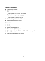
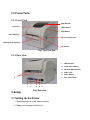
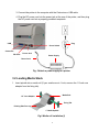
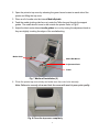
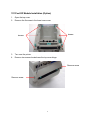
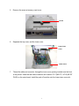
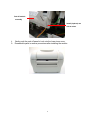
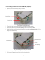
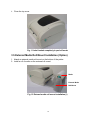
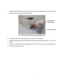
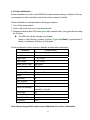
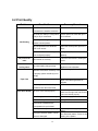
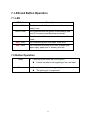
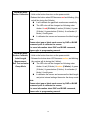
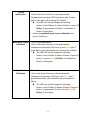
Fastmark M5 Plus Series
Direct Thermal Barcode Printer
User’s Guide
Document #120523 Rev-A
Contents
1. Introduction..............................................................................................1
2. Getting Started .........................................................................................1
2.1 Unpacking and Inspection ....................................................................1
2.2 Equipment Checklist ............................................................................1
2.3 Printer Parts .........................................................................................3
2.3.1 Front View ..................................................................................... 3
2.3.2 Rear View ...................................................................................... 3
3 Setup..........................................................................................................3
3.1 Setting Up the Printer ...........................................................................3
3.2 Loading Media Stock............................................................................4
3.3 Peel-Off Module Installation (Option) ...................................................6
3.4 Loading Labels for Peel-off Mode (Option)...........................................9
3.5 External Media Roll Mount Installation (Option) .................................10
3.6 Cutter Module Installation (Option).....................................................12
3.7 Loading Media in Cutter Mode ...........................................................15
3.8 Internal Ethernet Print Server Module Installation (Option) ................16
3.9 Diagnostic Tool ..................................................................................20
3.9.1 Start the Diagnostic Tool .............................................................. 20
3.9.2 Printer Function (Calibrate, Ethernet setup, RTC setup…) .......... 21
3.10. Install Memory Card ........................................................................21
4. Power on Utilities...................................................................................23
4.1 Gap/Black Mark Sensor Calibration ...................................................23
4.2 Gap/Black Mark Calibration, Self-test, Dump Mode ...........................24
4.3 Printer Initialization .............................................................................27
4.4 Black Mark Sensor Calibration ...........................................................28
4.5 Gap Sensor Calibration ......................................................................28
4.6 PAL application program ....................................................................28
5. Maintenance ...........................................................................................29
5.1 Cleaning .............................................................................................29
6. Troubleshooting.....................................................................................31
6.1 LED Status .........................................................................................31
6.2 Print Quality........................................................................................32
7. LED and Button Operation....................................................................33
7.1 LED ....................................................................................................33
7.2 Button Operation ................................................................................33
Revise History............................................................................................37
i
1. Introduction
Thank you for purchasing the AMT Datasouth M5 DT PLUS Direct Thermal Bar Code Printer.
Although the printer takes only a small amount of space, it delivers reliable, superior
performance.
This printer provides direct thermal printing at user selectable speeds of: 2.0, 3.0, 4.0 or 5.0
inches per second. It accepts roll feed, die-cut, and fan-fold labels for printing media. All
common bar codes formats are available. Fonts and bar codes can be printed in 4 directions,
8 different alphanumeric bitmap fonts and a build-in true type font capability. You will enjoy
high throughput for printing labels with this printer.
2. Getting Started
2.1 Unpacking and Inspection
This printer has been specially packaged to withstand damage during shipping. Please
carefully inspect the packaging and printer upon opening and prior to installation. Please
retain the packaging materials in case you need to reship the printer.
2.2 Equipment Checklist
Printer
User CD Disk (BarTender Ultralite, Printer User Manuals & Diagnostic Software)
Quick start guide
USB port cable
External universal switching power supply
Power Cord
Label Spindle
Fixing tab x2
1.5” core adapter x2
If any parts are missing, please contact the Customer Service Department of your
purchased reseller or distributor.
1
Optional Configurations
Peel off module assembly.
Guillotine cutter
Full cut:
Paper thickness: 0.06~ 0.19mm, 500,000 cuts
Partial cut:
Paper thickness: 0.06~0.12mm, 500,000 cuts
Paper thickness: 0.19mm 200,000 cuts
Main board integrated with internal Ethernet
Internal Ethernet print server module
Accessories
KP-200
KU-007 plus
External Ethernet print server
External wireless (802.11b/g) print server
External roll mount, media OD. 214 mm (8.4”) with 3” core label spindle
Contact CCD contact scanner
Long range linear image bar code scanner
2
2.3 Printer Parts
2.3.1 Front View
Clear Window
Top Cover
LED Indicator
Feed Button
Label Opening
Top Cover Open Lever
Backing Paper Opening
Front Panel
Fig.1 Top Front View
2.3.2 Rear View
1. USB Interface
2. Centronics Interface
3. RS-232C DB-9 Interface
4. Power Jack
5. Power Switch
6
6.
1
2
3
4
5
Fig.2 Rear View
3 Setup
3.1 Setting Up the Printer
1. Place the printer on a flat, secure surface.
2. Make sure the power switch is off.
3
Rear Label Guide
3. Connect the printer to the computer with the Centronics or USB cable.
4 Plug the DC power cord into the power jack at the rear of the printer, and then plug
the AC power cord into a properly grounded receptacle.
Plug
USB
Power Switch
Centronics
RS-232C
Power Jack
Power Supply
Power Cord
Fig. 5 Attach a power supply to a printer
3.2 Loading Media Stock
1. Insert spindle into a media roll (If your media core is 1 inch, remove the 1.5 inch core
adapter from the fixing tab).
Media Roll
1.5” Core Adapter
Fixing Tab
Printing Side Face up
1” Media Spindle
Fig 6 Media roll installation (I)
4
2. Open the printer’s top cover by releasing the green levers located on each side of the
printer and lifting the top cover.
3. Place a roll of media onto the internal Media Spindle.
4. Feed the media (printing side face up) under the Teflon bar and through the support
guides. The media should come to rest outside the printer. Refer to Fig #7.
5. Adjust the black center-biased media guides in or out by turning the adjustment knob so
they are slightly touching the edges of the media/backing.
Media Guide
Media Roll Mount
Adjustment Knob
Platen
Fig. 7 Media roll installation (II)
6. Close the printer top cover slowly and make sure the cover locks securely.
Note: Failure to securely close and lock the cover will result in poor print quality.
Fig. 8 Close the top cover completely
5
3.3 Peel-Off Module Installation (Option)
1.
2.
Open the top cover.
Remove the 6 screws in the lower inner cover.
Screws
Screws
3.
4.
Turn over the printer.
Remove two screws located near the top cover hinge.
Remove screw
Remove screw
6
5.
Remove the screw at memory card cover.
Screw
6.
Separate the top, inner, and the lower cover.
Lower inner
cover
Lower cover
7.
Thread the cable red connector through the inner cover opening located near the front
of the printer. Insert the red cable connector into location JP17 (M5 DT) / JP19 (M5 DT
PLUS) on the main board. Install the peel-off module onto the lower inner cover slot.
7
Peel-off module
assembly
Install (2-places) one
side at a time.
8.
9.
Gently push the peel-off panel to lock onto the lower inner cover.
Reassemble parts in reverse procedures after installing the module.
8
3.4 Loading Labels for Peel-off Mode (Option)
1. Open the peel-off module by pulling it forward.
Peel-off Roller
Peel-off Panel
Fig. 9 Open the peel-off panel
2. Thread the label, printing side facing up, through the support guides.
3. Thread the label through the liner opening, which is beneath the roller.
4. Adjust the black center-biased media guides by turning the adjustment knob to fit the
edge of the label/backing.
Adjustment Knob
Peel-Off Panel
Roller
Liner Opening
Fig. 10 Loading Labels for peel-off mode
5. Lift the peel-off panel up and back into the closed position.
9
6. Close the top cover.
Fig. 11 Label loaded completely in peel-off mode
3.5 External Media Roll Mount Installation (Option)
1. Attach an external media roll mount on the bottom of the printer.
2. Install a roll of media on the external roll mount.
Media
External Media
Roll Mount
Fig. 12 External media roll mount installation (I)
10
3. Feed the media (printing side face up) into the external opening located at the rear of the
printer and then through the media guides.
External Media
Feed Opening
Rear Media Guide
Fig. 13 External label roll mount installation (II)
4. Open the printer top cover by pulling the top cover open levers.
5. Continue feeding the media through the internal printer guides and place it on top of the
platen.
6. Adjust the media guides by turning adjustment knob to fit the edge of the media/backing.
7. Close the printer top cover.
11
3.6 Cutter Module Installation (Option)
1. Pull the top cover levers to open the top cover.
2. Remove the front panel from the lower cover. Pull straight up to remove.
3. Use a screwdriver to remove 6 screws on the lower inner cover.
Screws
Screws
Fig. 14 Remove 6 screws from lower inner cover
4. Turn over the printer.
5. Remove two screws located near the top cover hinge.
12
6. Remove the screw from the memory card cover, and left the cover off.
Memory Card
Cover Screw
7. Plug in the Cutter Driver IC at U14(M5 DT) / U30(M5 DT PLUS) socket on the main
board.
M5 DT Model
M5 DT PLUS Model
Note:
For Non-RoHS PCB, use cutter driver IC A3952SB
For RoHS PCB, use cutter driver IC A3953SB
13
8. Hold the lower cover and lift up the lower inner cover.
9. Thread the cutter module cable through the bezel.
10. Connect the cutter module cable to the 4-pin socket on printer PCB.
Bezel
Socket
Fig. 16 Cutter module harness arrangement
11. Reassemble the lower inner cover back onto the lower cover.
12. Install the cutter module into the slots of the printer.
Slots each side of
the printer
Fig. 17 Cutter module installation
13. Reassemble the parts in the reverse order.
14. Close the top cover.
14
3.7 Loading Media in Cutter Mode
1.
2.
3.
4.
Open the printer top cover.
Insert the spindle into the media roll.
Install a media roll onto the roll mount.
Thread the media, printing side face up, through the guides, platen and cutter module
outlet.
Media Guide
Adjustment Knob
Cutter Media Opening
Platen
Cutter
Fig. 18 Media installation in cutter mode
5. Adjust the black center-biased guides to fit edge of the media/backing.
6. Close the top cover
.
Fig. 19 Media installation in cutter mode completed
15
3.8 Internal Ethernet Print Server Module Installation (Option)
1. Break through the plastic partially connected at the rear side of lower cover RJ45
interface opening.
RJ45 interface opening
Remove the screw
2. Remove the screw from the main board. Fasten the metal and plastic standoff.
Plastic standoff
Metal standoff
16
3. Fasten the RJ45 connector daughter board on the plastic and metal standoff. The ground
wire from the mechanism must be screwed on the daughter board with metal standoff.
Ground wire
Screws
RJ45 connector daughter board
4. Connect the print server module interface cable (36PIN) and RJ45 interface cable to
print server module.
Print server module
interface cable
RJ45 interface cable
17
5. Remove the 2 screws from the motor bracket and 1 screw in the lower inner cover to
install the internal print server.
Screw
Screws
6. Install the print server module in printer lower inner cover with 3 screws.
Screw
Screws
Internal Print Server Module
18
7. Plug the RJ45 white connector to the RJ45 daughter board connector.
8. Plug the print server module interface cable to connector J1A and J1B on the PCB, the
left side harness (with red wire at the left side) is for J1A, the right side harness location is
for J1B.
M5 DT Model
M5 DT PLUS Model
9. Plug the 2 PIN connector on PCB JP26 (M5 DT ) / JP22 (M5 DT PLUS) connector for 5V
DC power.
19
3.9 Diagnostic Tool
The Diagnostic Utility is a tool that allows users to explore the printer's settings and
status; change printer settings; download graphics, fonts, and firmware; create printer
bitmap fonts; and to send additional commands to the printer. Using this convenient
tool, you can explore the printer status and settings and troubleshoot the printer.
Note: This utility works with printer firmware V6.00 and later versions.
3.9.1 Start the Diagnostic Tool
1. Double click on the Diagnostic tool icon
to start the software.
2. There are four features (Printer Configuration, File Manager, Bitmap Font Manager,
Command Tool) included in the Diagnostic utility.
20
3.9.2 Printer Function (Calibrate, Ethernet setup, RTC setup…)
1. Select the PC interface connected with bar code printer.
2. Click the “Function” button to setting.
3. The detail functions in the Printer Function Group are listed as below.
Function
Description
Factory Default
Initialize the printer and restore the settings to
factory default.
Dump Text
To activate the printer dump mode.
Configuration Page
Print printer configuration.
RTC Setup
Synchronize printer Real Time Clock with PC.
Calibrate Sensor
Calibrate the sensor specified in the Printer Setup
group media sensor field.
Reset Printer
Reboot the printer.
Print Test Page
Print a test page.
Ignore AUTO.BAS
Ignore the downloaded AUTO.BAS program.
Ethernet Setup
Setup the IP address, subnet mask, gateway for
the on board Ethernet.
Note:
For more information about Diagnostic Tool, please refer to the diagnostic utility quick start
guide in the CD disk \ Utilities directory.
3.10. Install Memory Card
1. Turn the printer over.
2. Remove 1 screw and open the memory card cover.
Memory Card Cover
21
3. Plug in the memory card on main board.
M5 DT Model (Option)
M5 DT PLUS Model (SD card)
4. Reinstall the memory card cover.
* Recommended SD card specification.
SD V 1.0, V 1.1
128MB
SD V 2.0 (SDHC)
4GB class 6
256MB
512MB
1GB
-Supported DOS FAT file system.
-Folders stored on the SD card should be in the 8.3 filename format.
-Approved SD card manufacturer: SanDisk, Transcend
22
4. Power on Utilities
There are six power-on utilities to set up and test printer hardware. These utilities are
activated by pressing FEED button and by turning on the printer power simultaneously.
The utilities are listed as below:
1. Gap/Black Mark sensor calibration
2. Gap/black mark sensor calibration, Self-test and Dump mode
3. Printer initialization
4. Black mark sensor calibration
5. Gap sensor calibration
6. Skip AUTO.BAS
4.1 Gap/Black Mark Sensor Calibration
Gap/black mark sensor sensitivity should be calibrated at the following conditions:
1. A brand new printer
2. Change label stock.
3. Printer initialization.
Please follow the steps below to calibrate the gap/black sensor:
1.Turn off the power switch.
2. Hold on the button then turn on the power switch.
3 Release the button when LED becomes red and blinking. (Any red will do during the 5
blinks).
It will calibrate the gap/black mark sensor sensitivity.
The LED color will be changed as following order
Amber
red (5 blinks)
amber (5 blinks)
green (5 blinks)
blinks)
red/amber (5 blinks)
solid green
It calibrates the sensor and measures the label length.
green/amber (5
Note:
Please select gap or black mark sensor by GAP or BLINE command prior to
calibrate the sensor.
For more information about GAP and BLINE command, please refer to
programming manual.
23
4.2 Gap/Black Mark Calibration, Self-test, Dump Mode
While calibrate the gap/black mark sensor, printer will measure the label length, print the
internal configuration (self-test) and then enter the dump mode.
Please follow the steps as below.
1.Turn off the power switch.
2. Hold on the button then turn on the power switch.
3. Release the button when LED becomes amber and blinking. (Any amber will do during
the 5 blinks).
The LED color will be changed as following order.
Amber
red (5 blinks)
amber (5 blinks)
green (5 blinks)
green/amber (5
blinks)
red/amber (5 blinks)
solid green
It calibrates the sensor and measures the label length and prints internal settings
then enter the dump mode.
Note:
Please select gap or black mark sensor by Diagnostic Tool or by GAP or BLINE
command prior to calibrate the sensor.
For more information about GAP and BLINE command, please refer to programming
manual.
24
Self-test
Printer will print the printer configuration after gap/black mark sensor calibration. Self-test
printout can be used to check if there is any dot damage on the heater element, printer
configurations and available memory space.
Self-test printout
Print head check pattern
Model name and F/W version
Printed mileage (meter)
Firmware checksum
Serial port configuration
Code page
Country code
Print speed (inch/sec)
Print darkness
Label size (inch)
Gap distance (inch)
Gap/black mark sensor sensitivity
Numbers of download files
Total & available memory space
Note:
1. The physical flash memory for RoHS compliant version is 2MB Flash and 2MB
DRAM (M5 DT Model) / 8MB SDRAM (M5 DT PLUS Model)
2. System occupies 960 KB in Flash memory so total flash memory space for user
downloading is 1088 KB
3. System occupies 1792 KB in DRAM so total DRAM memory space for user
downloading is 256 KB (M5 DT Model)
System occupies 7936 KB in SDRAM so total SDRAM memory space for user
downloading is 256 KB (M5 DT PLUS Model)
25
Dump mode
Printer will enter dump mode after printing printer configuration. In the dump mode, all
characters will be printed in 2 columns as following. The left side characters are received
from your system and right side data are the corresponding hexadecimal value of the
characters. It allows users or engineers to verify and debug the program.
Dump mode printout
Note: Turn off and on the power switch to reset the printer for normal printing.
26
4.3 Printer Initialization
Printer initialization is used to clear DRAM and restore printer settings to defaults. The only
one exception is ribbon sensitivity, which will note be restored to default.
Printer initialization is activated by the following procedures.
1. Turn off the power switch.
2. Hold on the button then turn on the power switch.
3. Release the button when LED turns green after 5 amber blinks. (Any green will do during
the 5 blinks).
The LED color will be changed as following:
Amber
blinks)
red (5 blinks)
amber (5 blinks)
green (5 blinks)
red/amber (5 blinks)
solid green
green/amber (5
Printer configuration will be restore to defaults as below after initialization.
Parameter
Default setting
Speed
127 mm/sec (5 ips)
Density
8
Label Width
4” (101.6 mm)
Label Height
4” (101.6 mm)
Media Sensor Type
Gap sensor
Gap Setting
0.12” (3.0 mm)
Print Direction
0
Reference Point
0,0 (upper left corner)
Offset
0
Tear Mode
On
Peel off Mode
Off
Cutter Mode
Off
Serial Port Settings
9600 bps, none parity,
8 data bits, 1 stop bit
Code Page
850
Country Code
001
Clear Flash Memory No
IP Address
DHCP
Note: Always do gap/black mark sensor calibration after printer initialization.
27
4.4 Black Mark Sensor Calibration
Set black mark sensor as media sensor and calibrate the black mark sensor.
Please follow the steps as below.
1. Turn off the power switch.
2. Hold on the button then turn on the power switch.
3. Release the button when LED turns green/amber after 5 green blinks. (Any green/amber
will do during the 5 blinks).
The LED color will be changed as following:
Amber
blinks)
red (5 blinks)
amber (5 blinks)
green (5 blinks)
red/amber (5 blinks)
solid green
green/amber (5
4.5 Gap Sensor Calibration
Set gap sensor as media sensor and calibrate the gap sensor.
Please follow the steps as below.
1. Turn off the power switch.
2. Hold on the button then turn on the power switch.
3. Release the button when LED turns red/amber after 5 green/amber blinks. (Any
red/amber will do during the 5 blinks).
The LED color will be changed as following:
Amber
red (5 blinks)
amber (5 blinks)
green (5 blinks)
green/amber (5
blinks)
red/amber (5 blinks)
solid green
4.6 PAL application program
PAL programming language allows user to download an auto execution file to flash memory.
The printer will run the PAL application program immediately when turning on printer power.
The PAL application program can be interrupted by the power-on utility.
Please follow the procedures below to skip a PAL application program:
1. Turn off printer power.
2. Press the FEED button and then turn on power.
3. Release the FEED button when LED becomes solid green.
The LED color will be changed as following:
Amber
red (5 blinks)
amber (5 blinks)
green (5 blinks)
blinks)
red/amber (5 blinks)
solid green
4. Printer will be interrupted to run the PAL application program.
28
green/amber (5
5. Maintenance
5.1 Cleaning
This session presents the clean tools and methods to maintain your printer.
1. Please use one of following material to clean the printer.
Cotton swab (Head cleaner pen)
Lint-free cloth
Vacuum / Blower brush
100% ethanol
2. The cleaning process is described as following
Printer Part
Method
Interval
1. Always turn off the printer
Clean the print head when
before cleaning the print head. changing a new label roll
2. Allow the print head to cool for a
minimum of one minute.
3. Use a cotton swab (Head
cleaner pen) and 100% ethanol
to clean the print head surface.
Print Head
1. Turn the power off.
2. Rotate the platen roller and
wipe it thoroughly with 100%
Platen Roller
ethanol and a cotton swab, or
lint-free cloth.
Clean the platen roller when
changing a new label roll
Tear Bar/Peel Use the lint-free cloth with 100% As needed
29
Bar
ethanol to wipe it.
Sensor
Compressed air or vacuum
Monthly
Exterior
Wipe it with water-dampened cloth As needed
Interior
Brush or vacuum
As needed
Note:
Do not touch printer head by hand. If you touch it careless, please use ethanol to clean
it.
Use 100% Ethanol. DO NOT use medical alcohol, which may damage the printer head.
Regularly clean the print head and supply sensors once change a new ribbon to keep
printer performance and extend printer life.
30
6. Troubleshooting
The following guide lists the most common problems that may be encountered when
operating this bar code printer. If the printer still does not function after all suggested
solutions have been invoked, please contact the Customer Service Department of your
purchased reseller or distributor for assistance.
6.1 LED Status
This section lists the common problems that according to the LED status and other
problems you may encounter when operating the printer. Also, it provides solutions.
LED Status
/ Color
OFF
Printer
Status
No response
Possible Cause
No power
Recovery Procedure
* Turn on the power switch.
* Check if the green LED is lit on power supply. If
it is not lit on, power supply is broken.
* Check both power connections from the power
cord to the power supply and from the power
supply to the printer power jack if they are
connected securely.
Solid Green
ON
The printer is ready to * No action necessary.
use
Green with
Pause
The printer is paused * Press the FEED button to resume for printing.
blinking
Red with
blinking
Error
The out of label or the 1. Out of label
printer setting is not
correct
* Load a roll of label and follow the instructions in
loading the media then press the FEED button to
resume for printing.
2. Printer setting is not correct
* Initialize the printer by instructions in “Power on
Utility” or “Diagnostic Tool”.
Note:
Printer status can be easily shown on the Diagnostic Tool. For more information about the Diagnostic
Tool, please refer to the instruction in the software CD disk.
31
6.2 Print Quality
Problem
Possible Cause
Check if interface cable is well
Recovery Procedure
Re-connect cable to interface.
connected to the interface connector.
The serial port cable pin configuration Please replace the cable with pin to
is not pin to pin connected.
Not Printing
pin connected.
The serial port setting is not consistent Please reset the serial port setting.
between host and printer.
The port specified in the Windows
Select the correct printer port in the
driver is not correct.
driver.
The Ethernet IP, subnet mask, gateway Configure the IP, subnet mask and
is not configured properly.
No print on the
label
Continuous
feeding labels
gateway.
Follow the instructions in loading the
Label loaded not correctly.
media.
The printer setting may go wrong.
Please do the initialization and
gap/black mark calibration.
Gap/black mark sensor sensitivity is not Calibrate the gap/black mark sensor.
set properly (sensor sensitivity is not
enough)
Paper Jam
Set label size exactly as installed
paper in the labeling software or
program.
Labels may be stuck inside the printer Remove the stuck label.
Make sure label size is set properly.
mechanism near the sensor area.
Poor Print Quality Top cover is not closed properly.
Close the top cover completely and
make sure the right side and left side
levers are latched properly.
Check if supply is loaded correctly.
Reload the supply.
Media are incompatible.
Change the label combination.
Check if dust or adhesives are
Clean the print head.
accumulated on the print head.
Check if print density is set properly.
Check print head test pattern if head
element is damaged.
32
Adjust the print density and print
speed.
Run printer self-test and check the
print head test pattern if there is dot
missing in the pattern.
7. LED and Button Operation
7.1 LED
LED Color
Description
Green/ Solid
This illuminates that the power is on and the device is
ready to use.
Green/ Flash
This illuminates that the system is downloading data
from PC to memory and the printer is paused.
Amber
This illuminates that the system is clearing data from
printer.
Red / Solid
This illuminates printer head open, cutter error.
Red / Flash
This illuminates a printing error, such as head open,
paper empty, paper jam, or memory error etc.
7.2 Button Operation
Feed
Pause
Press the button when the LED is green.
It feeds the label to the beginning of the next label.
Press the feed button during printing.
The printing job is suspended.
33
Gap/Black Mark 1.Turn off the power switch.
Sensor Calibration 2. Hold on the button then turn on the power switch.
3 Release the button when LED becomes red and blinking. (Any
red will do during the 5 blinks).
It will calibrate the gap/black mark sensor sensitivity.
The LED color will be changed as following order
Amber
red (5 blinks)
amber (5 blinks)
green
(5 blinks)
green/amber (5 blinks)
red/amber (5
blinks)
solid green
It calibrates the sensor and measures the label length.
Note:
Please select gap or black mark sensor by GAP or BLINE
command prior to calibrate the sensor.
For more information about GAP and BLINE command,
please refer to programming manual.
Gap/Black Mark 1.Turn off the power switch.
Sensor Calibratio, 2. Hold on the button then turn on the power switch.
3. Release the button when LED becomes amber and blinking.
Label Length
(Any amber will do during the 5 blinks).
Measurement,
The LED color will be changed as following order.
Self Test and enter
Amber
red (5 blinks)
amber (5 blinks)
green
Dump Mode
(5 blinks)
green/amber (5 blinks)
red/amber (5
blinks)
solid green
It calibrates the sensor and measures the label length
and prints internal settings then enter the dump mode.
Note:
Please select gap or black mark sensor by GAP or BLINE
command prior to calibrate the sensor.
For more information about GAP and BLINE command,
please refer to programming manual.
34
Printer
Initialization
1. Turn off the power switch.
2. Hold on the button then turn on the power switch.
3. Release the button when LED turns green after 5 amber
blinks. (Any green will do during the 5 blinks).
The LED color will be changed as following:
Amber
blinks)
blinks)
red (5 blinks) amber (5 blinks) green (5
green/amber (5 blinks)
red/amber (5
solid green
Always do gap/black mark sensor calibration after
printer initialization.
Black Mark Sensor 1. Turn off the power switch.
2. Hold on the button then turn on the power switch.
Calibration
3. Release the button when LED turns green/amber after 5
green blinks. (Any green/amber will do during the 5 blinks).
The LED color will be changed as following:
Amber red (5 blinks) amber (5 blinks) green (5
blinks)
blinks)
Gap Sensor
Calibration
green/amber (5 blinks)
solid green
red/amber (5
1. Turn off the power switch.
2. Hold on the button then turn on the power switch.
3. Release the button when LED turns red/amber after 5
green/amber blinks. (Any red/amber will do during the 5
blinks).
The LED color will be changed as following:
Amber red (5 blinks) amber (5 blinks) green (5
blinks)
blinks)
green/amber (5 blinks)
solid green
35
red/amber (5
Skip AUTO.BAS
1. Turn off printer power.
2. Press the FEED button and then turn on power.
3. Release the FEED button when LED becomes solid green.
The LED color will be changed as following:
Amber
red (5 blinks)
amber (5 blinks)
green (5
blinks)
green/amber (5 blinks)
red/amber (5 blinks)
solid green
4. Printer will be interrupted to run the AUTO.BAS program.
36
Revise History
Date
Content
Editor
9-14-08
Pre-production Release
J. Nolan
37
Document #120523 Rev-A
Corporate Headquarters
Manufacturing/Service
803 Camarillo Springs Road, Suite-D
Camarillo, CA 93012
TEL: 800.215.9192
FAX: 805.484.5282
Web site: www.AMTDatasouth.com
5033 Sirona Drive, Suite-800
Charlotte, NC 28273
TEL: 800.476.2120
FAX: 704.525.6104