1
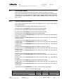
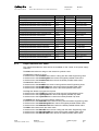
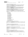
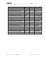
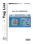
Technical
Information
Manual
Revision n. 6
1 February 2007
MOD. A3486
3-PHASE 220/400 VAC TO
2X2 KW/1X4 KW 48 VDC
NPO:
00120/04:A3486.MUTx/06
MANUAL REV. 6
CAEN will repair or replace any product within the guarantee period if the Guarantor declares that the
product is defective due to workmanship or materials and has not been caused by mishandling,
negligence on behalf of the User, accident or any abnormal conditions or operations.
CAEN declines all responsibility for damages or
injuries caused by an improper use of the Modules due
to negligence on behalf of the User. It is strongly
recommended to read thoroughly the CAEN User's
Manual before any kind of operation.
This product must be installed by qualified personnel; in order to be CE
compliant it requires 3-phase EMC filter type EPCOS B84143-A16-R105
on the mains supply cable; this filter does not support operation in
hostile areas (magnetic field).
CAEN reserves the right to change partially or entirely the contents of this Manual at any time and without
giving any notice.
Disposal of the Product
The product must never be dumped in the Municipal Waste. Please check your local
regulations for disposal of electronics products.
Document type:
User's Manual (MUT)
Title:
A3486 3Phase 220/400Vac to 2x2kW/1x4kW 48Vdc
Revision date:
01/02/2007
Revision:
6
TABLE OF CONTENTS
1.
2.
3.
EASY EMBEDDED ASSEMBLY SYSTEM ............................................................................................5
1.1
FUNCTIONAL DESCRIPTION .....................................................................................................................5
1.2
THE CAEN MULTICHANNEL POWER SUPPLY SYSTEM OVERVIEW .........................................................6
1.3
THE MOD. A1676A BRANCH CONTROLLER OVERVIEW .........................................................................8
A3486 3-PHASE 220/400VAC TO 2X2KW/1X4KW 48VDC .................................................................9
2.1
TECHNICAL DESCRIPTION .......................................................................................................................9
2.2
CHANNEL CHARACTERISTIC TABLE .......................................................................................................9
2.3
FRONT AND BACK PANEL COMPONENTS................................................................................................10
2.4
TECHNICAL SPECIFICATIONS ................................................................................................................11
2.4.1
Packaging ....................................................................................................................................................11
2.4.2
Rear panel connections, switches and displays ...........................................................................................11
2.4.3
Front panel connections, switches and displays ..........................................................................................16
SAFETY INFORMATION AND INSTALLATION REQUIREMENTS............................................18
3.1
3.1.1
4.
GENERAL SAFETY INFORMATION ..........................................................................................................18
Injury Precautions .......................................................................................................................................18
3.2
SAFETY TERMS AND SYMBOLS ON THE PRODUCT ................................................................................18
3.3
INSTALLATION......................................................................................................................................19
OPERATING MODES .............................................................................................................................20
4.1
OUTPUT CONTROL AND MONITORING ...................................................................................................20
4.2
TRACKING MODE .............................................................................................................................23
4.2.1
Internal Channel OPC Items .......................................................................................................................23
4.2.2
Output Channel OPC Items .........................................................................................................................24
LIST OF FIGURES
FIG. 1.1 – SYSTEM’S BLOCK DIAGRAM ...................................................................................................................6
FIG. 2.1 – A3486 FRONT AND BACK PANEL ........................................................................................................10
FIG. 2.2 – REMOTE VOLTAGE SENSING SCHEME ...................................................................................................12
FIG. 2.3 – 48V STATUS IN SCHEME .....................................................................................................................12
FIG. 2.4 – BUS CONNECTION WITH A3486 MODULES ...........................................................................................13
FIG. 2.5 – BUS CONNECTION WITH A3486 MODULES AND EASY CRATES ...........................................................14
FIG. 2.6 – BUS CONNECTION WITH A3486 MODULES, EASY CRATES AND SPLIT CABLES ....................................15
FIG. 2.7 –9 PIN DB-TYPE MALE CONNECTOR SIGNALS .........................................................................................15
NPO:
00120/04:A3486.MUTx/06
Filename:
A3486_REV6.DOC
Number of pages:
27
Page:
3
Document type:
User's Manual (MUT)
Title:
A3486 3Phase 220/400Vac to 2x2kW/1x4kW 48Vdc
Revision date:
01/02/2007
Revision:
6
FIG. 2.8 – INTERLOCK DIAGRAM ..........................................................................................................................16
FIG. 3.1 – VENTILATION-WARNING LABEL ..........................................................................................................19
LIST OF TABLES
TABLE 1.1 – TECHNICAL SPECIFICATIONS OF THE SY 1527 MAINFRAME ...............................................................7
TABLE 2.1 – TECHNICAL SPECIFICATIONS OF THE A3486 48 V POWER SOURCE ...................................................9
TABLE 4.1 – CH0 PARAMETERS (BOARD PARAMETERS)......................................................................................20
TABLE 4.2 – CH1..2 PARAMETERS (OUTPUT CHANNEL PARAMETERS).................................................................21
TABLE 4.3 – STATUS WORD SIGNIFICANT BITS .....................................................................................................21
TABLE 4.4 – INTERNAL CHANNEL ITEMS .............................................................................................................23
TABLE 4.5 – OUTPUT CHANNEL ITEMS.................................................................................................................26
NPO:
00120/04:A3486.MUTx/06
Filename:
A3486_REV6.DOC
Number of pages:
27
Page:
4
Document type:
User's Manual (MUT)
Title:
A3486 3Phase 220/400Vac to 2x2kW/1x4kW 48Vdc
Revision date:
01/02/2007
Revision:
6
1. EASY Embedded Assembly System
1.1
Functional description
EASY (Embedded Assembly SYstem) is the new CAEN power supply solution for
operation in magnetic field and radioactive environment. CAEN has been involved for
more than a decade in developing different solutions for the main LHC experiments,
where the electronic equipment of the experiment is dealing with high dose radiation and
intense magnetic field. In order to provide safe and reliable operations in such hostile
areas, CAEN started tests with rad-tolerant components and magnetic field resistant
solutions, patenting the new technology that is now used in this new line of products.
Moreover, though designed for harsh environment, the EASY modules can work also in
normal condition with excellent performance. In the new architecture, the power supply
can be located directly in the hostile area, where the EASY modules provide a wide
variety of output voltages to satisfy the requirements of most detectors and front-end
electronics. The control of the EASY power supply system is done remotely using a
Branch Controller (Mod. A1676A) plugged in a SY1527 or SY2527 mainframe located in
the control room. Each A1676A branch controller can handle up to 6 EASY crates: in this
way, one SY1527 power supply system, for example, housing up to 16 A1676A boards,
can handle up to 96 EASY systems. The EASY crate can house up to 10 boards,
depending on the boards’ width. The branch controller is the interface between the
mainframe (SY1527 or SY2527) and the remote boards in the EASY crate: its role is to
configure the EASY channels as if they belong to the supply unit slot in which the branch
controller is located. All the channels of the EASY boards will be considered as channels
of the branch control board, thus hugely increasing the number of channels the system
can handle. Through the mainframe, the provided and fully reliable OPC server permits
an immediate and “automatic” interfacing with the custom control software; moreover, a
C-library for Windows and Linux is available as well. The EASY crate can be used with
an air and/or water intercooler and its standard width fit the rack mounting. Fig. 1.1
shows the system’s block diagram.
NPO:
00120/04:A3486.MUTx/06
Filename:
A3486_REV6.DOC
Number of pages:
27
Page:
5
Document type:
User's Manual (MUT)
Title:
A3486 3Phase 220/400Vac to 2x2kW/1x4kW 48Vdc
Revision date:
01/02/2007
CONTROL ROOM
Revision:
6
HOSTILE AREA
CONTROL
LOGIC
3-phase 220/400 V 50/400 Hz
DC-DC
V+
S+
SV-
DC-DC
V+
S+
SV-
DC-DC
V+
S+
SV-
DC-DC
V+
S+
SV-
DC-DC
V+
S+
SV-
DC-DC
V+
S+
SV-
A3486 Module
CONTROL
LOGIC
A1676A BRANCH CONTROLLER
SY1527 SYSTEM MAINFRAME
Control Bus
A3486 Module
SY1527
Fig. 1.1 – System’s block diagram
1.2
The CAEN Multichannel Power Supply System Overview
The SY1527 system is the fully equipped experiment version of a new line of power
supply systems which represent CAEN's latest proposal in the matter of High Voltage
and Low Voltage Power Supplying. This system outlines a completely new approach to
power generation and distribution by allowing the housing, in the same mainframe, of a
wide range of boards with different functions, such as High/Low Voltage boards, generic
I/O boards (temperature, pressure monitors, etc.) and branch controllers, where the latter
are used to control other remote generators and distributors. Modularity, flexibility and
reliability are the key-points of its design, enabling this module to meet the requirements
needed in a wide range of experimental conditions, which range from those of LHC
experiments, where the features of this model find prior application, to those of other less
challenging, but still demanding, High Energy Physics experiments.
The mainframe is housed in a 19"-wide, 8U-high euro-mechanics rack and hosts four
main sections:
- the Board Section, with 16 slots to house boards, distributors and branch controllers;
- the Fan Tray Section, housing 6 fans arranged on two rows;
- the Power Supply Section, which consists of the primary power supply and up to 3
power supply units;
- the CPU and Front Panel Section which includes all interface facilities.
The User Software Interface features the usual friendliness of the previous CAEN
systems which now also includes a 7.7" colour LCD. A wide choice of interface facilities
provides full communication compatibility with the previous systems and the feasibility of
controlling heterogeneous external devices. Modularity has been one of the leading
criteria in the design and development of the system: both the Power Supply Section and
the Board Section are completely modular. The Power Supply Section allows different
configurations with up to 3 power supply units per mainframe (up to 2250 W), while the
Board Section can house up to 16 boards able to fulfil different functions. A complete line
of power supply boards and distributors has been specially developed for this new
system. The minimum system configuration consists of the primary power supply, one
NPO:
00120/04:A3486.MUTx/06
Filename:
A3486_REV6.DOC
Number of pages:
27
Page:
6
Document type:
User's Manual (MUT)
Title:
A3486 3Phase 220/400Vac to 2x2kW/1x4kW 48Vdc
Revision date:
01/02/2007
Revision:
6
Power Supply Unit and one board. The system allows also to deal with power supply
solutions composed by “branch controllers” (housed in the system main frame) and ondetector “remote boards” (manufactured in order to be magnetic field and radiation
tolerant). Channel trip control on other crates is performed via four external differential
trip lines. A sophisticated trip handling via software allows to control and correlate trip
conditions on the channels of the crate as well as of other crates connected to it. Live
insertion and extraction of the boards, which reduces the down time of the global system,
and easy access to the computing core and peripherals of the system complete the
system flexibility. Easy interfacing is another key-point of the SY1527 system, which can
be connected to SY127 and SY527 systems. The Ethernet interface (TCP/IP) allows both
an easy Telnet access and the connection via OPC Server to a SCADA control system.
Enhanced software programming features a unified command set independent from the
interface used to communicate with the system. The Power Supply Section and Board
Section can be externally synchronised via front panel connectors. Multi-layered access
to the system via Intranet is foreseen through the management of several custom user
profiles. In particular, three different access levels have been implemented: Guest, User
and Administrator, each of which with password protection. Handy maintenance and
upgrading, which constitute a major issue in the reliability of a system, are further
guaranteed by the possibility of accessing and servicing the system via network facilities.
Actually, the Telnet access facility allows remote debugging and technical support of the
system, including future firmware upgrading. For a detailed description of the SY 1527
Universal Multichannel Power Supply System please refer to the SY 1527 User's Manual.
Table 1.1 – Technical specifications of the SY 1527 mainframe
Packaging
- 19"-wide, 8U-high Euro-mechanics rack;
- Depth: 720 mm.
Weight
-Mainframe (*): 24 kg
-Mod. A1532: 3.2 kg
Voltage range: 100/230 V
Power requirements
Frequency: 50/60 Hz
Power: 3400 W
Max. number of boards per crate
16
Max. nr. of power supply units per crate
3
Primary power supply output (Mod.
A 1531)
± 12 V, 8 A
Power supply unit output (Mod. A 1532)
+48 V, 15.6 A
Max. output power
+5 V, 20 A
2250 W
Operating temperature
From 0°C (dry atmosphere) to +40°C
Storage temperature
From -20°C (dry atmosphere) to +50°C
(*) One Primary Power Supply (Mod. A 1531) and one Power Supply Unit (Mod. A 1532) are
included; boards are not included.
NPO:
00120/04:A3486.MUTx/06
Filename:
A3486_REV6.DOC
Number of pages:
27
Page:
7
Document type:
User's Manual (MUT)
1.3
Title:
A3486 3Phase 220/400Vac to 2x2kW/1x4kW 48Vdc
Revision date:
01/02/2007
Revision:
6
The Mod. A1676A Branch Controller overview
The Mod. A1676A EASY Branch Controller is implemented in a single width
SY1527/SY2527 board. Once plugged in, the Branch Controller must be linked to the
EASY crates (placed in the “hostile area”), via front panel connectors (Control and Power
Supply). The A1676A is the interface between the mainframe and the remote boards in
the EASY crate. It configures the EASY channels as if they belong to the slot in which the
branch controller is located: the channels of the EASY boards operate as channels of the
A1676A. Up to six EASY crates can be controlled by one A1676A. The provided software
tool allows the User to configure the A1676A to operate with any EASY crate layout.
NPO:
00120/04:A3486.MUTx/06
Filename:
A3486_REV6.DOC
Number of pages:
27
Page:
8
Document type:
User's Manual (MUT)
Title:
A3486 3Phase 220/400Vac to 2x2kW/1x4kW 48Vdc
Revision date:
01/02/2007
Revision:
6
2. A3486 3-Phase 220/400Vac to 2X2kW/1X4kW 48Vdc
2.1
Technical description
The CAEN Mod. A3486 is a two channel 220/400 Vac – 48 Vdc converter, which allows
to integrate into the EASY channels control also the management of the 48 V power
supplies. Each channel provides a 2 kW output and can be tracked in order to obtain one
4 kW output. This module is designed to work as main converter in LHC hostile areas,
thus completing the EASY system. Features include local or remote control, overload
protection and local or remote inhibit function.
The module front panel houses LEDs and channels monitor signals. The channel outputs
are provided through Anderson Power single pin connectors.
2.2
Channel Characteristic Table
Table 2.1 – Technical specifications of the A3486 48 V Power Source
Packaging
positive
Polarity
3-phase 220/400 V 50/400 Hz1
AC input
Output Voltage
Max. Output Power
Voltage Ripple
1
19"-wide, 3U-high Euro-mechanics rack;
Depth: 50 cm.
44 ÷ 52 V adjustable via software
4000 W
< 100 mV rms
The Mod. A3486 cannot be supplied indifferently with either 220 Vac or 400 Vac triphase: it has to be
configured by the manufacturer according to the external power supply to be used.
NPO:
00120/04:A3486.MUTx/06
Filename:
A3486_REV6.DOC
Number of pages:
27
Page:
9
NPO:
00120/04:A3486.MUTx/06
Filename:
A3486_REV6.DOC
MAIN
A
K
S-
OUTS+
OUT+
SENSE CONNECTOR
CH1
-OUT CH1+
ON
S+
OUT+
OVC
STATUS
MAX
DROP
INT.
FAIL
S
T
A
T
U
S
48V OK
IN OUT
48V IN
- IN +
48V SERVICE
ON
INDEPENDENT
PARALLEL
K
GND
A
VCC
ON
OVC
INT.
FAIL
OFF
ON
LOCAL INPUT
ON
OFF
TERMINATION
ENABLE
COMM
POWER
EASY BUS
STATUS
MAX
DROP
CHANNEL 1
INTERLOCK
DISABLE
ENABLE
OUTPUT
INPUT
INPUT
OUTPUT
EARTH
Title:
A3486 3Phase 220/400Vac to 2x2kW/1x4kW 48Vdc
CH0
S-
OUT-
SENSE CONNECTOR
-OUT CH0+
INTERLOCK
VCC
GND
TRACKING
2x2KW / 1x4KW 48Vdc POWER SUPPLY
2.3
DISABLE
ENABLE
CHANNEL 0
Mod. A3486
Document type:
User's Manual (MUT)
Revision date:
01/02/2007
Revision:
6
Front and back panel components
Fig. 2.1 – A3486 Front and Back Panel
Number of pages:
27
Page:
10
Document type:
User's Manual (MUT)
Title:
A3486 3Phase 220/400Vac to 2x2kW/1x4kW 48Vdc
2.4
Technical Specifications
2.4.1
Packaging
Revision date:
01/02/2007
Revision:
6
The module is housed in a 3U 19” Euro Rack, 50 cm deep.
2.4.2
Rear panel connections, switches and displays
The Module rear panel houses the following components:
2.4.2.1 MAIN
This section provides the connections for the mains power supplies and includes:
1 3-phase (400 Vac) connector Harting HAN Q 7/0 female insert 09.12.007.3101;
configuration pin: Harting HAN Q 7/0 female coding pin 09.12.000.9901;
case: Harting HAN Bulkhead mounting code 09.20.003.0301;
male pin contact: Harting 09.33.000.6102
1 3-phase switch
3 20A Fuses
2.4.2.2 48V SERVICE
This section provides the input of 48 V supply for auxiliary low voltages and includes:
2 APP30 1317G4 type connectors (OR’ed)
1 2A Fuse
2 Red LEDs (48 V IN and 48V OK)
48 V IN LED lights up as the external 48V is present on the input; 48V OK LED lights up
as the 48V is available for the internal electronics.
2.4.2.3 CHANNEL OUT±
This section provides the channels output and includes:
2 APP PC5933T type connectors (channels output)
2 AMP 280372-2 type connectors (sense)
2 red LEDs (channel ON)
The channels output connectors provide the 48V output. The Sense lines are used to
compensate for the voltage drop over the cable. Voltage is monitored directly at the load
by an high input impedance differential amplifier through the sense wires; the voltage
sensing circuit is schematically illustrated in the figure below.
NPO:
00120/04:A3486.MUTx/06
Filename:
A3486_REV6.DOC
Number of pages:
27
Page:
11
Document type:
User's Manual (MUT)
Title:
A3486 3Phase 220/400Vac to 2x2kW/1x4kW 48Vdc
OUT
+
Revision date:
01/02/2007
Revision:
6
Rcable
10KΩ
S+
L
O
A
D
VMON
S-
10 KΩ
OUT
-
Rcable
Fig. 2.2 – Remote voltage sensing scheme
When the sense wires are connected to the load (pin 2 = S- and pin 3 = S+ of the fourpin sense connector on back panel), the Vset value equals the voltage on the load; if the
sense wires are not connected (to the load), Vset will equal the voltage on the connector.
If sense wires will not be used, then is necessary to short circuit pin 1 = Out- with pin 2
= S- and pin 3 = S+ with pin 4 = Out+.
2.4.2.4 STATUS
This section provides the Status line for failure detection and includes:
1 Input AMP 280372-2 type connector
1 Output AMP 280372-2 type connector
Through this input the remote EASY board microcontroller can detect failures in supply
voltages and consequently enables PS channels ramping down, while service supply
voltage is provided by a back up battery.
The status input circuit is described in the following figure:
P1
P2
330 Ohm
Pin4
Pin3
Pin2
Pin1
~10 mA
IN OUT
S
T
A
T
U
S
P3
P4
Fig. 2.3 – 48V Status IN scheme
It can work in two ways:
PASSIVE OPERATION: it is necessary to short circuit pin 1 (the 1st from bottom to top)
with pin 2 (the 2nd from bottom to top), and pin 3 (the 3rd from bottom to top) with pin 4
(the 4th from bottom to top).
ACTIVE OPERATION: it is necessary to send a voltage level (for example a TTL; the
recommended current is about 10 mA) between pin 2 and pin 3 (high = STATUS OK; low
= STATUS FAIL ), leaving pin 1 and pin 4 disconnected.
NPO:
00120/04:A3486.MUTx/06
Filename:
A3486_REV6.DOC
Number of pages:
27
Page:
12
Document type:
User's Manual (MUT)
Title:
A3486 3Phase 220/400Vac to 2x2kW/1x4kW 48Vdc
Revision date:
01/02/2007
Revision:
6
The output connector allows to pass the Status information to other converters and
crates: it can be connected with the STATUS connector of EASY3000 crates and
provides the following information:
STATUS OK = Both A3486 Channels ON
STATUS FAIL = At least one of A3486 Channels OFF
2.4.2.5 EASY BUS
This section provides the link for the module connection with the A1676A and the
EASY3000 crates and includes:
2 INPUT internally wired 50 Pin flat male connectors
2 OUT internally wired 50 Pin flat male connectors
1 Local Input 9 Pin DB-type male connector (to be used with split cables, see A1676A
User’s Manual)
1 Termination switch (see figures for termination usage)
The Input/Output Flat connectors are redundant: either one or the other can be used,
according to cabling configuration; they shall be used to connect the module to the
EASY Bus communication link, as shown in the following schemes:
a) If the A1676A handles a remote chain composed only by A3486 modules, there are
two types of possible connections, as shown in the following figure:
DB
output
input
input
A3486#0
output
output
input
input
A3486#0
output
DB
term
on
term
on
DB
DB
output
input
input
output
output
A3486#1
output
A1676A
A3486#2
output
DB
input
DB
input
term
on
output
term
on
A3486#5
output
DB
input
DB
input
term
on
output
term
on
output
input
input
input
output
input
input
A3486#5
input
A3486#2
output
A3486#1
output
A1676A
term
on
term
on
Fig. 2.4 – Bus connection with A3486 modules
The termination is required on each A3486 in both cases.
NPO:
00120/04:A3486.MUTx/06
Filename:
A3486_REV6.DOC
Number of pages:
27
Page:
13
Document type:
User's Manual (MUT)
Title:
A3486 3Phase 220/400Vac to 2x2kW/1x4kW 48Vdc
Revision date:
01/02/2007
Revision:
6
b) If the A1676A handles a chain which includes both EASY crates and A3486 modules,
a possible connection is the following:
DB
input
output
EASY3000#0
output
output
input
input
A3486#0
output
DB
EASY
term.
term
off
DB
input
output
output
DB
EASY3000#2
input
output
DB
output
EASY
term.
output
DB
DB
EASY3000#5
output
EASY
term.
input
term
off
output
input
input
input
input
A3486#5
output
A3486#2
output
A1676A
EASY3000#1
term
off
output
input
output
input
A3486#1
output
DB
EASY
term.
term
off
Fig. 2.5 – Bus connection with A3486 modules and EASY crates
The A3486 is handled as a crate slot and the communication is terminated by the crates
backplane. The A3486 termination must be OFF.
N.B.: in this case the A3486 INPUT connector must be connected with the EASY3000
Crate INPUT connector.
c) EASY crates and A3486 modules can be also connected with the A1676A by using
split cables, as shown in the following figure (termination provided by the crates
backplane).
NPO:
00120/04:A3486.MUTx/06
Filename:
A3486_REV6.DOC
Number of pages:
27
Page:
14
Document type:
User's Manual (MUT)
Title:
A3486 3Phase 220/400Vac to 2x2kW/1x4kW 48Vdc
Revision date:
01/02/2007
Revision:
6
DB
input
output
output
EASY3000#0
DB
EASY3000#1
input
DB
output
EASY
term.
output
term
off
DB
EASY3000#2
input
DB
output
EASY
term.
output
term
off
DB
DB
EASY3000#5
term
off
input
EASY
term.
output
term
off
output
input
input
input
output
input
input
input
input
A3486#5
input
A3486#2
A1676A
output
A3486#1
output
A3486#0
output
DB
EASY
term.
Fig. 2.6 – Bus connection with A3486 modules, EASY crates and split cables
In the two latter cases one A1676A branch handles one A3486 and one EASY crate.
5 HVCLK_H0
9 HVCLK_L0
4 SYNCLF_H0
8 SYNCLF_L0
3 DATA_H0
7 DATA_L0
2 /RECL_H0
6 /RECL_L0
1 GND LINK
Fig. 2.7 –9 Pin DB-type male connector signals
2.4.2.6 EARTH
This section provides the Earth auxiliary reference and includes:
NPO:
00120/04:A3486.MUTx/06
Filename:
A3486_REV6.DOC
Number of pages:
27
Page:
15
Document type:
User's Manual (MUT)
Title:
A3486 3Phase 220/400Vac to 2x2kW/1x4kW 48Vdc
Revision date:
01/02/2007
Revision:
6
1 Earth RADIALL R921921 type connector
2.4.3
Front panel connections, switches and displays
The Module front panel houses the following components:
2.4.3.1 POWER
This section allows to turn the module ON/OFF and includes:
1 LEMO 00 connector (ENABLE)
1 Bistable switch (ON/OFF)
1 green LED (COMM)
The module can be turned ON (enabled) only if a 50 Ohm termination is inserted in the
Enable LEMO 00 connector.
The ON/OFF switch allows to enable/disable the power supply (general ON/OFF of the
module) when the 48V Service is active.
The COMM LED lights up as the communications with the A1676A take place.
2.4.3.2 CHANNEL INTERLOCK
This section allows to enable/disable the module output and includes:
1 AMP 280372-2 type connector
1 Bistable switch (ENABLE/DISABLE)
1 red LED
In order to enable the output channel the switch must be set on “ENABLE”, then the
Interlock can work in two ways:
PASSIVE OPERATION: it is necessary to short circuit pin 1 (“GND”, the first from left to
right) with pin 2 (“K=katode”), and pin 3 (“A=anode”) with pin 4 (“VCC”).
ACTIVE OPERATION: it is necessary to send a voltage level (for example a TTL; the
recommended current is about 10 mA) between pin 2 = katode and pin 3 = anode (high =
interlock disabled, the channel can be turned on; low = interlock enabled, the channel
cannot be turned on), leaving pin 1 and pin 4 disconnected.
The LED is ON when the Board is enabled.
VCC
A
330 Ohm
~10 mA
K
GND
Fig. 2.8 – Interlock diagram
NPO:
00120/04:A3486.MUTx/06
Filename:
A3486_REV6.DOC
Number of pages:
27
Page:
16
Document type:
User's Manual (MUT)
Title:
A3486 3Phase 220/400Vac to 2x2kW/1x4kW 48Vdc
Revision date:
01/02/2007
Revision:
6
2.4.3.3 CHANNEL STATUS
This section includes four LEDs:
ON LED (red): lights up as the channel is on.
INT. FAIL LED (red): lights up in case of internal power supply failures. After the Internal
Fail cause is removed, the LED remains on, unless a “Clear Alarm” is performed.
OVC LED (red): lights up as the channel is in overcurrent (Imon = Iset/Imax hardware).
After the Overcurrent cause is removed, the LED remains on, unless a “Clear Alarm” is
performed.
MAX DROP LED (red): lights up as the maximum allowed voltage drop is exceeded; i.e.:
when Sense Wires are used and the detected drop is larger than 6 V, the channel is
turned off automatically since it is not possible to recover it.
After the Maximum Drop cause is removed, the LED remains on, unless a “Clear Alarm”
is performed.
2.4.3.4 TRACKING
This section allows to track the channels and includes:
1 Slide switch (Parallel/Independent)
1 green LED
Channels can be tracked in order to obtain one 4 kW output: for this purpose it is
necessary to:
- turn the module off
- remove the screw-lock protection cap
- set the tracking switch on the “Parallel” position
- connect the output cables in parallel on the load
- connect the sense wires (if used, see § 2.4.2.3); only one pair is required
- install the screw-lock protection cap
- turn the module on
When the channels are tracked, the channels settings (see § 4.1) act on both channels;
in particular: if one channel is disabled via Interlock, neither the other is active; Vset/Iset
must be programmed on Output Channel 0, their value is copied on Output Channel 1
automatically. The green LED lights up as the channels are tracked.
NPO:
00120/04:A3486.MUTx/06
Filename:
A3486_REV6.DOC
Number of pages:
27
Page:
17
Document type:
User's Manual (MUT)
Title:
A3486 3Phase 220/400Vac to 2x2kW/1x4kW 48Vdc
Revision date:
01/02/2007
Revision:
6
3. Safety information and installation requirements
3.1
General safety information
This section contains the fundamental safety rules for the installation and operation of the
boards. Read thoroughly this section before starting any procedure of installation or
operation of the product.
3.1.1
Injury Precautions
Review the following precautions to avoid injury and prevent damage to this product or
any products connected to it. To avoid potential hazards, use the product only as
specified. Only qualified personnel should perform service procedures.
Avoid Electric Overload.
To avoid electric shock or fire hazard, do not apply a voltage to a load that is outside the
range specified for that load.
Avoid Electric Shock.
To avoid injury or loss of life, do not connect or disconnect cables while they are
connected to a voltage source.
Do Not Operate Without Covers.
To avoid electric shock or fire hazard, do not operate this product with covers or panels
removed.
Do Not Operate in Wet/Damp Conditions.
To avoid electric shock, do not operate this product in wet or damp conditions.
Do Not Operate in an Explosive Atmosphere.
To avoid injury or fire hazard, do not operate this product in an explosive atmosphere.
Do Not Operate With Suspected Failures.
If you suspect there is damage to this product, have it inspected by qualified service
personnel.
3.2
Safety Terms and Symbols on the Product
These terms may appear on the product:
•
DANGER indicates an injury hazard immediately accessible as you read the
marking.
•
WARNING indicates an injury hazard not immediately accessible as you read the
marking.
•
CAUTION indicates a hazard to property including the product.
The following symbols may appear on the product:
NPO:
00120/04:A3486.MUTx/06
Filename:
A3486_REV6.DOC
Number of pages:
27
Page:
18
Document type:
User's Manual (MUT)
3.3
Title:
A3486 3Phase 220/400Vac to 2x2kW/1x4kW 48Vdc
Revision date:
01/02/2007
DANGER
ATTENTION
High Voltage
Refer to Manual
Revision:
6
Installation
The CAEN Mod. A3486 is designed to work as main converter in LHC hostile areas, thus
completing the EASY system. It must be connected to the EASY Bus just like EASY
Crates; for more information about operation with the EASY3000 System, please refer to
the Mod. A1676A Branch Controller documentation.
It is necessary to provide the Mod. A3486 the proper ventilation by using for example the
CAEN Mod. A3000F Fan Unit.
Fig. 3.1 – Ventilation-warning Label
The Mod. A1676A is a single-width board for the SY1527/2527/3527 systems. At power
ON the SY1527 system processor will scan all the slots in the crate to find out where the
module is plugged and what kind of module it is.
The A1676A must be connected to the EASY3000/4000 remote crates through the
control lines. The control connectors are placed on the A1676A front panel and on the
EASY3000/4000 back or front panel respectively.
This product must be installed by qualified personnel; in order to be
CE compliant it requires 3-phase EMC filter type EPCOS B84143-A16R105 on the mains supply cable; this filter does not support
operation in hostile areas (magnetic field).
NPO:
00120/04:A3486.MUTx/06
Filename:
A3486_REV6.DOC
Number of pages:
27
Page:
19
Document type:
User's Manual (MUT)
Title:
A3486 3Phase 220/400Vac to 2x2kW/1x4kW 48Vdc
Revision date:
01/02/2007
Revision:
6
4. Operating modes
The Mod. A3486 can be controlled, either locally or remotely, through the SY 1527
software interface.
For details on the EASY3000 System, please refer to the User's Manual of the A1676A
Branch Controller. For details on SY 1527 system operation, please refer to the User's
Manual of this product.
ATTENTION
THE MOD. A1676A and A3486 BOARDS REQUIRE
SY 1527 FIRMWARE VERSION 2.01.00 OR LATER
4.1
Output control and monitoring
The control software handles two types of channels: the Channel 0, which is a “virtual”
internal channel and it is used to manage the board parameters, and the Channnel 1
and 2, which are the actual output channels. A1676A Branch Controller parameters are
listed in the relevant User's Manual.
Table 4.1 – CH0 Parameters (Board parameters)
Name
Dir
Sign
ValType
Name
SET
UNSIGNED
STRING
Rel
MON
UNSIGNED
NUMERIC
12VPwS
MON
UNSIGNED
Sync
MON
HVSync
Min
Max
Res
UM
OnStr
OffStr
1.00
99.99
0.01
NONE
ON OFF
Fail
Ok
UNSIGNED
ON OFF
Fail
Ok
MON
UNSIGNED
ON OFF
Fail
Ok
StatusIn
MON
UNSIGNED
ON OFF
Fail
Ok
Tracking
MON
UNSIGNED
ON OFF
On
Off
SerNum
MON
UNSIGNED
NUMERIC
RemBdName
MON
UNSIGNED
ON OFF
A3486
A3486
1
65535
1
NONE
Name
allows to assign a symbolic name to the board
Rel
allows to readout the module firmware release.
12VPwS
allows to readout the status of the +/-12V voltages
generated inside the module.
If 12VPwS = Fail all channels are turned OFF.
Sync
allows to readout the status of the 50Hz synchronisation
signal (EASY BUS) provided by the A1676A Branch
Controller .
If Sync = Fail all channels are turned OFF.
NPO:
00120/04:A3486.MUTx/06
Filename:
A3486_REV6.DOC
Number of pages:
27
Page:
20
Document type:
User's Manual (MUT)
Title:
A3486 3Phase 220/400Vac to 2x2kW/1x4kW 48Vdc
Revision date:
01/02/2007
Revision:
6
HVSync
allows to readout the status of the 625KHz EASY BUS clock
signal provided by the A1676A
If HVSync = Fail the 625KHz signal is generated by the
board itself.
StatusIn
allows to readout the back panel STATUS IN signal.
If StatusIn = Fail all the channels are turned OFF.
Tracking
allows to readout the module operating mode selected via
front panel switch.
SerNum
allows to readout the module serial number.
RemBdName
allows to readout the module name.
Table 4.2 – CH1..2 Parameters (output channel parameters)
Name
Dir
Sign
ValType
Min
Max
Res UM
Name
SET
UNSIGNED
STRING
Temp
MON
SIGNED
NUMERIC
0
70
1
CELSIUS
Status
MON
UNSIGNED
STATUS
0
0
0
---
Pw
SET
UNSIGNED
ON_OFF
Trip
SET
UNSIGNED
NUMERIC
0.0
2.0
0.1
SEC
VCon
MON
UNSIGNED
NUMERIC
0.0
55.0
0.1
VOLT
SVMax
SET
UNSIGNED
NUMERIC
44.0
52.0
0.1
VOLT
VMon
MON
UNSIGNED
NUMERIC
0.0
52.0
0.1
VOLT
GlbOffEn
SET
UNSIGNED
GlbOnEn
SET
RemIlk
OnStr OffStr
On
Off
ON_OFF
En
Dis
UNSIGNED
ON_OFF
En
Dis
MON
UNSIGNED
ON_OFF
Yes
No
V0Set
SET
UNSIGNED
NUMERIC
44.0
52.0
0.1
VOLT
IMon
MON
UNSIGNED
NUMERIC
00.0
40.0
0.1
AMPERE
I0Set
SET
UNSIGNED
NUMERIC
00.0
40.0
0.1
AMPERE
IntFail
MON
UNSIGNED
ON_OFF
Yes
No
MaxDrop
MON
UNSIGNED
ON_OFF
Yes
No
Name
allows to assign a symbolic name to the channel
Temp
allows to readout the Temperature value.
If Temp > 70°C the channel is turned OFF.
Status
allows to readout the channel status value.
The status word significant bits are:
Table 4.3 – Status word significant bits
Status
Name
Bit 0
ON/OFF
Bit 3
OVC
NPO:
00120/04:A3486.MUTx/06
Filename:
A3486_REV6.DOC
Meaning
Over Current : IMon > I0set
Number of pages:
27
Page:
21
Document type:
User's Manual (MUT)
Title:
A3486 3Phase 220/400Vac to 2x2kW/1x4kW 48Vdc
Revision date:
01/02/2007
Status
Name
Meaning
Bit 4
OVV
Over Voltage : VMon > V0set + 5V
Bit 5
UNV
Under Voltage : VMon < V0set - 5V
Bit 9
TRIP
Channel in OVC for a duration > TRIP
Bit 11
UNPLUGGED
Fail in communication with A1676A Branch Controller
Bit 13
OVP
Over Voltage Protection : Output voltage > 55V
Bit 15
TERR
Temperature Error : temperature > 70°C
Revision:
6
If a channel is in ‘TRIP’, ‘OVP’,or ‘TERR’, it is turned OFF.
Before turning one channel ON, every fail cause must be removed via the ‘Clear Alarm’
command, sent by the Sy1527/Sy2527 system.
Pw
allows to send the ON/OFF command to the channel.
Trip
allows to set the Trip time.
If the channel Over Current (Imon >= I0set) lasts more than
the Trip time, the channel is turned OFF.
If Trip = 2 sec the channel in OVC is not turned OFF.
VCon
allows to readout the voltage on the output connector.
if VCon > 55V the channel is turned OFF.
SVmax
allows to set the upper limit of V0Set.
(V0Set cannot exceed SVMax).
VMon
allows to readout the voltage on the load.
GlbOnEn
allows to enable the channel to respond to a GlobalOn
command provided by the A1676A.
All the channels with GlbOnEn = En are turned ON any time
the A1676A broadcasts a GlobalOn command.
GlbOffEn
allows to enable the channel to respond to a GlobalOff
command provided by the A1676A.
All the channels with GlbOffEn = En are turned OFF any time
the A1676A broadcasts a GlobalOff command.
RemIlk
allows to readout the status of the Interlock signal on the
front panel.
If RemIlk = Yes the channel is turned OFF.
V0Set
allows to set the output voltage.
IMon
allows to readout the current value delivered by the channel.
I0Set
allows to set the current threshold value.
IntFail
allows to readout the Internal Fail condition, provided by the
channel in order to signal an internal failure.
If IntFail = Yes the channel is turned OFF.
MaxDrop
allows to readout the Max Drop condition, provided by the
channel in order to signal that the drop between the voltage
on the load and the voltage on the output connector is too big
(it could be a cable problem).
If MaxDrop = Yes the channel is turned OFF.
NPO:
00120/04:A3486.MUTx/06
Filename:
A3486_REV6.DOC
Number of pages:
27
Page:
22
Document type:
User's Manual (MUT)
4.2
Title:
A3486 3Phase 220/400Vac to 2x2kW/1x4kW 48Vdc
Revision date:
01/02/2007
Revision:
6
TRACKING Mode
The 2 48V/40A channels can be tracked in order to obtain one 48V/80 A channel.
The used Set parameters are those referred to CH1, while the Monitor parameters are
independent. To turn ON the tracked channels both must be enabled (Enable LED: ON).
If one channel is either disabled or in ‘TRIP’, ‘OVP’,or ‘TERR’, both are turned OFF; see
also § 2.4.3.4.
4.2.1
Internal Channel OPC Items
This chapter describes the items which are available for the control of the internal
channel (Channel 0).
The Name item allows to assign to the channel a symbolic name.
A read access to the SerNum item returns the board serial number.
A read access to the Rel item returns the board firmware release.
A read access to the SerNum item returns the board serial number.
A read access to the Tracking item returns the Tracking status.
A read access to the Tracking#CoOpen item returns back the label “Off” associated to
Tracking =independent.
A read access to the Tracking#CoClose item returns back the label “On” associated to
Tracking =parallel.
A read access to the 12VPwS item returns the internal ±12 V status.
A read access to the 12VPwS#CoOpen item returns back the label “Off” associated to
12VPwS=FAIL.
A read access to the 12VPwS#CoClose item returns back the label “On” associated to
12VPwS=OK.
A read access to the StatusIn item returns the StatusIn connector signal.
A read access to the StatusIn#CoOpen item returns back the label “Off” associated to
StatusIn = FAIL.
A read access to the StatusIn#CoClose item returns back the label “On” associated to
StatusIn = OK.
A read access to the Sync item returns the external 50 Hz status.
A read access to the Sync#CoOpen item returns back the label “Off” associated to
Sync=FAIL.
A read access to the Sync#CoClose item returns back the label “On” associated to
Sync=OK.
A read access to the HVSync item returns the external 625 Hz status.
A read access to the HVSync#CoOpen item returns back the label “Off” associated to
HVSync=FAIL.
A read access to the HVSync#CoClose item returns back the label “On” associated to
HVSync=OK.
A read access to the RemBdName item returns a string with the board name.
Table 4.4 – Internal Channel items
ItemID
Data Type
Access
Description
PowerSupplyName.BoardXX.ChanYYY.Name
String
R/W
Channel name
PowerSupplyName.BoardXX.Chan0.SerNum
2-byte int.
R
Board serial number
NPO:
00120/04:A3486.MUTx/06
Filename:
A3486_REV6.DOC
Number of pages:
27
Page:
23
Document type:
User's Manual (MUT)
4.2.2
Title:
A3486 3Phase 220/400Vac to 2x2kW/1x4kW 48Vdc
Revision date:
01/02/2007
Revision:
6
ItemID
Data Type
Access
Description
PowerSupplyName.BoardXX.Chan0.Rel
String
R
Board firmware release
PowerSupplyName.BoardXX.Chan0.Tracking
boolean
R
Tracking status
PowerSupplyName.BoardXX.Chan0.Tracking#CoOpen
string
R
Tracking open label
PowerSupplyName.BoardXX.Chan0.Tracking#CoClose
string
R
Tracking close label
PowerSupplyName.BoardXX.Chan0.12VPwS
boolean
R
12VPS status
PowerSupplyName.BoardXX.Chan0.12VPwS#CoOpen
string
R
12VPS open label
PowerSupplyName.BoardXX.Chan0.12VPwS#CoClose
string
R
12VPS close label
PowerSupplyName.BoardXX.Chan0.StatusIn
boolean
R
StatusIn status
PowerSupplyName.BoardXX.Chan0.StatusIn#CoOpen
string
R
StatusIn open label
PowerSupplyName.BoardXX.Chan0.StatusIn#CoClose
string
R
StatusIn close label
PowerSupplyName.BoardXX.Chan0.Sync
boolean
R
Sync status
PowerSupplyName.BoardXX.Chan0.Sync#CoOpen
string
R
Sync open label
PowerSupplyName.BoardXX.Chan0.Sync#CoClose
string
R
Sync close label
PowerSupplyName.BoardXX.Chan0.HVSync
boolean
R
HVSync status
PowerSupplyName.BoardXX.Chan0.HVSync#CoOpen
string
R
HVSync open label
PowerSupplyName.BoardXX.Chan0.HVSync#CoClose
string
R
HVSync close label
PowerSupplyName.BoardXX.Chan0.RemBdName
string
R
Board name
Output Channel OPC Items
This chapter describes the items which are available for the control of the power supply
channels.
The Name item allows to assign to the channel a symbolic name.
The V0set item allows to set V0.
A read access to the V0set#EU item returns a string with the V0set Engineering Units.
A read access to the V0set#HighEU item returns the highest possible V0set value.
A read access to the V0set#LowEU item returns the lowest possible V0set value.
The I0set item allows to set I0.
A read access to the I0set#EU item returns a string with the I0set Engineering Units.
A read access to the I0set#HighEU item returns the highest possible I0set value.
A read access to the I0set#LowEU item returns the lowest possible I0set value.
The Trip item allows to program the trip time.
A read access to the Trip#EU item returns a string with the Trip Engineering Units.
A read access to the Trip#HighEU item returns the highest possible Trip value.
A read access to the Trip#LowEU item returns the lowest possible Trip value.
The SVMax item allows to set the software voltage limit.
A read access to the SVMax#EU item returns a string with the SVMax Engineering Units.
A read access to the SVMax#HighEU item returns the highest possible SVMax value.
A read access to the SVMax#LowEU item returns the lowest possible SVMax value.
The VMon item returns back the VMon value.
A read access to the VMon#EU item returns a string with the VMon Engineering Units.
A read access to the VMon#HighEU item returns the highest possible VMon value.
A read access to the VMon#LowEU item returns the lowest possible VMon value.
NPO:
00120/04:A3486.MUTx/06
Filename:
A3486_REV6.DOC
Number of pages:
27
Page:
24
Document type:
User's Manual (MUT)
Title:
A3486 3Phase 220/400Vac to 2x2kW/1x4kW 48Vdc
Revision date:
01/02/2007
Revision:
6
The VCon item returns back the VCon value.
A read access to the VCon#EU item returns a string with the VCon Engineering Units.
A read access to the VCon#HighEU item returns the highest possible VCon value.
A read access to the VCon#LowEU item returns the lowest possible VCon value.
The IMon item returns back the IMon value.
A read access to the IMon#EU item returns a string with the IMon Engineering Units.
A read access to the IMon#HighEU item returns the highest possible IMon value.
A read access to the IMon#LowEU item returns the lowest possible IMon value.
The Temp item returns back the channel temperature.
A read access to the Temp#EU item returns a string with the Temp Engineering Units.
A read access to the Temp#HighEU item returns the highest possible Temp value.
A read access to the Temp#LowEU item returns the lowest possible Temp value.
A read access to the Status item returns back a 16 bit pattern indicating channel status,
as follows:
Bit 0: ON/OFF
Bit 1: don’t care
Bit 2: don’t care
Bit 3: OverCurrent
Bit 4: OverVoltage
Bit 5: UnderVoltage
Bit 6: don’t care
Bit 7: Over HVmax
Bit 8: don’t care
Bit 9: Internal Trip
Bit 10: Calibration Error
Bit 11: don’t care
Bit 12: don’t care
Bit 13: OverVoltage Protection
Bit 14: Power Fail
Bit 15: Temperature Error
The RemIlk item returns back the Remote Interlock value.
A read access to the RemIlk#CoOpen returns back the label “Off” associated to RemIlk
=0.
A read access to the RemIlk#CoClose returns back the label “On” associated to RemIlk
=1.
The IntFail item returns back the Internal Failure value.
A read access to the IntFail#CoOpen returns back the label “Off” associated to IntFail
=0.
A read access to the IntFail#CoClose returns back the label “On” associated to IntFail
=1.
The MaxDrop item returns back the Maximum Drop status value.
A read access to the MaxDrop#CoOpen returns back the label “Off” associated to
MaxDrop =0.
A read access to the MaxDrop#CoClose returns back the label “On” associated to
MaxDrop =1.
The Pw item allows to switch ON/OFF the channel.
A read access to the Pw#CoOpen returns back the label “Off” associated to Pw=0.
A read access to the Pw#CoClose returns back the label “On” associated to Pw=1.
The GlbOnEn item enables the channel to respond to the A1676A Global On command.
NPO:
00120/04:A3486.MUTx/06
Filename:
A3486_REV6.DOC
Number of pages:
27
Page:
25
Document type:
User's Manual (MUT)
Title:
A3486 3Phase 220/400Vac to 2x2kW/1x4kW 48Vdc
Revision date:
01/02/2007
Revision:
6
A read access to GlbOnEn#CoOpen returns back the label “Off” associated to
GlbOnEn=0.
A read access to GlbOnEn#CoClose returns back the label “On” associated to
GlbOnEn=1.
The GlbOffEn item enables the channel to respond to the A1676A Global Off command.
A read access to GlbOffEn#CoOpen returns back the label “On” associated to
GlbOffEn=0.
A read access to GlbOffEn#CoClose returns back the label “Off” associated to
GlbOffEn=1.
Table 4.5 – Output Channel items
ItemID
Data Type
Access
Description
PowerSupplyName.BoardXX.ChanYYY.Name
String
R/W
Channel name
PowerSupplyName.BoardXX.ChanYYY.V0Set
4-byte real
R/W
Set V0 voltage limit
PowerSupplyName.BoardXX.ChanYYY.V0Set#EU
String
R
V0set EU
PowerSupplyName.BoardXX.ChanYYY.V0Set#HighEU
8-byte real
R
V0set upper limit
PowerSupplyName.BoardXX.ChanYYY.V0Set#LowEU
8-byte real
R
V0set lower limit
PowerSupplyName.BoardXX.ChanYYY.I0Set
4-byte real
R/W
Set I0 current limit
PowerSupplyName.BoardXX.ChanYYY.I0Set#EU
String
R
I0set EU
PowerSupplyName.BoardXX.ChanYYY.I0Set#HighEU
8-byte real
R
I0set upper limit
PowerSupplyName.BoardXX.ChanYYY.I0Set#LowEU
8-byte real
R
I0set lower limit
PowerSupplyName.BoardXX.ChanYYY.Trip
4-byte real
R/W
Set trip time
PowerSupplyName.BoardXX.ChanYYY.Trip#EU
String
R
Trip time EU
PowerSupplyName.BoardXX.ChanYYY.Trip#HighEU
8-byte real
R
Trip time upper limit
PowerSupplyName.BoardXX.ChanYYY.Trip#LowEU
8-byte real
R
Trip time lower limit
PowerSupplyName.BoardXX.ChanYYY.SVMax
4-byte real
R/W
Set software voltage limit
PowerSupplyName.BoardXX.ChanYYY.SVMax #EU
String
R
SVMax EU
PowerSupplyName.BoardXX.ChanYYY.SVMax#HighU
8-byte real
R
SVMax upper limit
PowerSupplyName.BoardXX.ChanYYY.SVMax#LowEU
8-byte real
R
SVMax lower limit
PowerSupplyName.BoardXX.ChanYYY.VMon
4-byte real
R
VMon
PowerSupplyName.BoardXX.ChanYYY.Vmon#EU
String
R
VMon EU
PowerSupplyName.BoardXX.ChanYYY.Vmon#HighU
8-byte real
R
VMon upper limit
PowerSupplyName.BoardXX.ChanYYY.Vmon#LowEU
8-byte real
R
VMon lower limit
PowerSupplyName.BoardXX.ChanYYY.VCon
4-byte real
R
VCon
PowerSupplyName.BoardXX.ChanYYY.VCon#EU
String
R
VCon EU
PowerSupplyName.BoardXX.ChanYYY.VCon#HighU
8-byte real
R
VCon upper limit
PowerSupplyName.BoardXX.ChanYYY.VCon#LowEU
8-byte real
R
VCon lower limit
PowerSupplyName.BoardXX.ChanYYY.Imon
4-byte real
R
IMon
PowerSupplyName.BoardXX.ChanYYY.Imon#EU
String
R
IMon EU
PowerSupplyName.BoardXX.ChanYYY.Imon#HighU
8-byte real
R
IMon upper limit
PowerSupplyName.BoardXX.ChanYYY.Imon#LowEU
8-byte real
R
IMon lower limit
PowerSupplyName.BoardXX.ChanYYY.Temp
4-byte real
R
Board temperature
PowerSupplyName.BoardXX.ChanYYY.Temp#EU
String
R
Temperature EU
PowerSupplyName.BoardXX.ChanYYY.Temp#HighEU
8-byte real
R
Temp upper limit
NPO:
00120/04:A3486.MUTx/06
Filename:
A3486_REV6.DOC
Number of pages:
27
Page:
26
Document type:
User's Manual (MUT)
Title:
A3486 3Phase 220/400Vac to 2x2kW/1x4kW 48Vdc
Revision date:
01/02/2007
Revision:
6
ItemID
Data Type
Access
Description
PowerSupplyName.BoardXX.ChanYYY.Temp#LowEU
8-byte real
R
Temp lower limit
PowerSupplyName.BoardXX.ChanYYY.Status
2-byte integer
R
Channel status
PowerSupplyName.BoardXX.ChanYYY.TripInt
4-byte real
R/W
Internal Trip
PowerSupplyName.BoardXX.ChanYYY.TripInt#EU
String
R
TripInt EU
PowerSupplyName.BoardXX.ChanYYY.TripInt#HighU
8-byte real
R
TripInt upper limit
PowerSupplyName.BoardXX.ChanYYY.TripInt#LowEU
8-byte real
R
TripInt lower limit
PowerSupplyName.BoardXX.ChanYYY.RemIlk
Boolean
R/W
Remote interlock ON/OFF
PowerSupplyName.BoardXX.ChanYYY.RemIlk#CoClose
String
R
Rem. interlock close label
PowerSupplyName.BoardXX.ChanYYY.RemIlk#CoOpen
String
R
Rem. interlock open label
PowerSupplyName.BoardXX.ChanYYY.IntFail
Boolean
R
Internal fail ON/OFF
PowerSupplyName.BoardXX.ChanYYY.IntFail#CoClose
String
R
Internal fail close label
PowerSupplyName.BoardXX.ChanYYY.IntFail#CoOpen
String
R
Internal fail open label
PowerSupplyName.BoardXX.ChanYYY.MaxDrop
Boolean
R
Max Drop ON/OFF
PowerSupplyName.BoardXX.ChanYYY.MaxDrop#CoClose
String
R
Max Drop close label
PowerSupplyName.BoardXX.ChanYYY.MaxDrop#CoOpen
String
R
Max Drop open label
PowerSupplyName.BoardXX.ChanYYY.Pw
Boolean
R/W
Power ON/OFF
PowerSupplyName.BoardXX.ChanYYY.Pw#CoClose
String
R
Pw close label
PowerSupplyName.BoardXX.ChanYYY.Pw#CoOpen
String
R
Pw open label
PowerSupplyName.BoardXX.ChanYYY.GlbOnEn
boolean
R/W
Enable global ON
PowerSupplyName.BoardXX.ChanYYY.GlbOnEn#CoClose
string
R
GlbOnEn close label
PowerSupplyName.BoardXX.ChanYYY.GlbOnEn#CoOpen
string
R
GlbOnEn open label
PowerSupplyName.BoardXX.ChanYYY.GlbOffEn
boolean
R/W
Enable global OFF
PowerSupplyName.BoardXX.ChanYYY.GlbOffEn#CoClose
string
R
GlbOffEn close label
PowerSupplyName.BoardXX.ChanYYY.GlbOffEn#CoOpen
string
R
GlbOffEn open label
NPO:
00120/04:A3486.MUTx/06
Filename:
A3486_REV6.DOC
Number of pages:
27
Page:
27