1
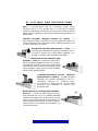
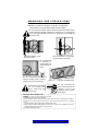
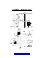
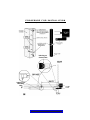
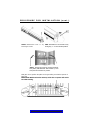
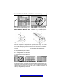
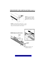
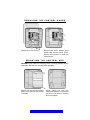
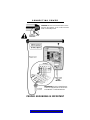
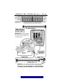
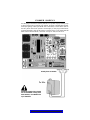
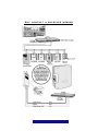
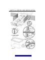
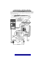
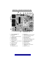
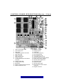
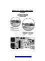
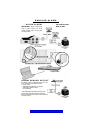
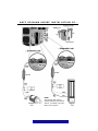
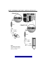
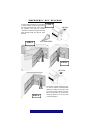
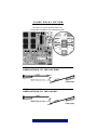
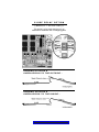
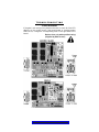
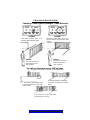
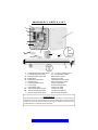
T A B L E
O F
C O N T E N T S
ATTENTION: This handbook is exclusively for qualified installation personal, and assistance
and/or maintenance service. - The performances indicated in this handbook are valid only if
a correct assembly has been carried out.
CLICK
THE
TOPIC
OF
YOUR
CHOICE
TABLE OF CONTENTS…………………………………………………………
1
UL LISTINGS AND INSTRUCTIONS……………………………………………
4-5
WARNINGS AND PRECAUTIONS………………………………………………
6
PROCEDURE FOR INSTALLATION………………………………………………
7-11
CONTROL BOARD BOX & HOW TO REMOVE CONTROL BOARD………………
12
CONNECTING POWER……………………………………………………………
13
CONNECTING POWER MASTER / SLAVE…………………………………………
14
CHOOSING MOVEMENT DIRECTION……………………………………………
15
CURRENT SENSOR ADJUSTMENT………………………………………………
15
POWER SUPPLY…………………………………………………………………
16
DRY CONTACT & RECEIVER WIRING……………………………………………… 17
SAFETY AND CENTER LOOP INSTALLATION ……………………………………… 18
PHOTO CELL INSTALLATION……………………………………………………… 19
CONTROL BOARD DESCRIPTION…………………………………………………
20
CONTROL BOARD DESCRIPTION MASTER / SLAVE ……………………………… 21
MAGLOCK & ALARM CONNECTORS ……………………………………………… 22
BURGLAR ALARM ………………………………………………………………… 23
GATE OPENING INSIDE INSTALLATION …………………………………………… 24
GATE OPENING OUTSIDE INSTALLATION……………………………………………25
EMERGENCY KEY RELEASE………………………………………………………… 26
CLOSE DELAY OPTION (MASTER / SLAVE ONLY) OPENING INSIDE……………… 27
CLOSE DELAY OPTION (MASTER / SLAVE ONLY) OPENING OUTSIDE …………
28
TROUBLESHOOTING…………………………………………………………… 29-30
MIRACLE•1 PARTS LIST …………………………………………………………
31
FEATURES AND SPECIFICATIONS ………………………………………………… 32
Do not
touch me
unless you are an
authorized service
technician!
© 1998 ELITE ACCESS SYSTEMS, INC.
All rights reserved. No part of this
Handbook may be reproduced by any
means without the expressed written
permission of the publisher. Materials,
components and specifications are
subject to change without notice.
RELEASE 1
UL LISTINGS AND INSTRUCTIONS
INSTALLATION INSTRUCTIONS REGARDING THE GATE OPERATOR
A) Install the gate operator only when:
1) The operator is appropriate for the construction and the usage
Class of the gate.
2) All openings of a horizontal slide gate are guarded or
screened from the bottom of the gate to a minimum of 4 feet
(1.2 m) above the ground to prevent a 2 1/4inch (57.15 mm)
diameter sphere from passing through the openings
anywhere in the gate, and in that portion of the adjacent
fence that the gate covers in the open position.
3) All exposed pinch points are eliminated or guarded, and
4) Guarding is supplied for exposed rollers.
B) The operator is intended for installation only on gates used for vehicles.
Pedestrians must be supplied with a separate access opening.
C) The gate must be installed in a location so that enough clearance is
supplied between the gate and adjacent structures when opening and
closing to reduce the risk of entrapment. Swinging gates shall not
open into public access areas.
D) The gate must be properly installed and work freely in both directions
prior to the installation of the gate operator.
E) F) Controls must be far enough from the gate so that the user is
prevented from coming in contact with the gate while operating the
controls. Controls intended to be used to reset an operator after 2
sequential activations of the entrapment protection device or devices
must be located in the line of sight of the gate outdoor or easily
accessible controls shall have a security feature to prevent unauthorized use.
G) All warning signs and placards must be installed where visible in the
area of the gate.
BACK
TO
TA B L E
OF
CONTENTS
UL LISTINGS AND INSTRUCTIONS
H) For a gate operator utilizing a non-contact sensor such as a photo beam:
1) See instructions on the placement of non-contact sensor for
each Type of application,
2) Care shall be exercised to reduce the risk of nuisance tripping,
such as when a vehicle trips the sensor while the gate still
moving, and
3) One or more non-contact sensors shall be located where the
risk of entrapment or obstruction exists, such as the perimeter
reachable by a moving gate or barrier.
I) For a gate operator utilizing a contact sensor such as an edge sensor:
1) One or more contact sensors shall be located at the leading
edge, trailing edge and postmounted both inside and outside
of a vehicular horizontal slide gate.
2) One or more contact sensors shall be located at the bottom
edge of a vehicular vertical lift gate.
3) One or more contact sensors shall be located at the pinch point
of a vehicular vertical pivot gate.
4) A hardwired contact sensor shall be located and its wiring arranged so
that the communication between the sensor and the gate operator is
not subjected to mechanical damage.
5) A wireless contact sensor such as the one that transmits radio
frequency (RF) signals to the gate operator for entrapment
protection functions shall be located where the transmission of
the signals are not obstructed or impeded by building structures,
natural landscaping or similar obstruction. A wireless contact sensor
shall function under the intended end-use conditions.
BACK
TO
TA B L E
OF
CONTENTS
UL LISTINGS AND INSTRUCTIONS
IMPORTANT SAFETY INSTRUCTIONS
WARNING - To reduce the risk of injury or death:
1. READ AND FOLLOW ALL INSTRUCTIONS.
2. Never let children operate or play with gate controls. Keep the
remote control away from children.
3. Always keep people and objects away from the gate while the
gate is in operation. NO ONE SHOULD CROSS THE PATH OF
A MOVING GATE.
4. Test the gate operator monthly. The gate MUST reverse on
contact with a rigid object or stop when an object activates
the non-contact sensors. After adjusting the force or the limit of
travel, retest the gate operator, Failure to adjust and retest the gate
operator properly can increase the risk of injury or death.
5. Use the emergency release only when the gate is not moving. Make
sure the power for the gate operator is off.
6. KEEP GATES PROPERLY MAINTAINED. Read the manual. Have a
qualified service person make repairs to the gate or gate hardware.
7. The entrance is for vehicles only. Pedestrians must use separate
entrance.
8. SAVE THESE INSTRUCTIONS.
BACK
TO
TA B L E
OF
CONTENTS
UL LISTINGS AND INSTRUCTIONS
Gate – A moving barrier such as a swinging, sliding, raising
lowering, rolling, or like, barrier, that is a stand-alone passage
barrier or is that portion of a wall or fence system that controls entrance
and/or egress by persons or vehicles and completes the perimeter of a
defined area.
Vehicular horizontal slide-gate operator (or system) – A
vehicular gate operator (or system) that controls a gate which slides in a
horizontal direction that is intended for use for vehicular entrance or exit
to a drive, parking lot, or the like.
Residential vehicular gate operator – Class I – A
vehicular gate operator (or system) intended for use in
a home of one-to four single family dwelling, or a
garage or parking area associated therewith.
Commercial/General access vehicular gate
operator – Class II – A vehicular gate operator (or system) intended for use in a commercial location or building such as a multi-family
housing unit (five or more single family units)
hotel, garages, retail store or other building
servicing the general public.
Commercial/General access vehicular
gate operator – Class III – A vehicular gate
operator (or system) intended for use in a
industrial location
or building
such
as a factory or loading dock area or other
locations not intended to service the
general public.
Restricted access vehicular gate operator –
Class IV – A vehicular gate operator (or system) intended for use in a guarded industrial
location or building such as an airport security
area or other restricted access locations not
servicing the general public, in which unauthorized access is prevented via supervision by
security personnel.
BACK
TO
TA B L E
OF
CONTENTS
WARNINGS AND PRECAUTIONS
WARNING: TO REDUCE THE RISK OF INJURY TO PERSONS
THE MIRACLE•1 IS FOR VEHICULAR GATE USE ONLY
Be sure to read and follow all these important instructions before installation of the gate operator. Elite Access Systems, Inc. is not responsible for improper installations or failure to comply with local building and
electrical codes.
Not for installation on any
pedestrian gates.
Not for installation on any pedestrian passages or doorways.
Do not install next
to sprinklers or
any area that may
expose bottom to
water.
Do not install upside down. Do not
install on pickets, weld a reinforcement bar across several pickets.
Do not install
on uphill or downhill gates.
Do not over-bend the
wire connection from the
operator. To do so will
cause the wires to eventually break.
If the timer is to be left in
the “on” position, then
add a safety loop and
center loop.
IMPORTANT SAFETY INSTRUCTIONS
WARNING - To reduce the risk of severe injury or death:
1. READ AND FOLLOW ALL INSTRUCTIONS.
2. Never let children operate or play with gate controls. Keep the remote control away from children.
3. Always keep the moving gate in sight and away from people and objects until it is completely
closed.
NO ONE SHOULD CROSS THE PATH OF THE MOVING GATE.
4. KEEP GATES PROPERLY MAINTAINED. Read the owner’s manual. Have a qualified service person
periodically inspect and make repairs to gate hardware.
5. SAVE THESE INSTRUCTIONS.
BACK
TO
TA B L E
OF
CONTENTS
P R O C E D U R E F O R I N S T A L L AT I O N
O p e n To T h e I n s i d e
10.5”
8.5”
25.75”
7.75”
6”
90°/105°
6”
Indexing
on
Central
Hole
Indexing on
Mounting Hole
BACK
TO
TA B L E
OF
CONTENTS
P R O C E D U R E F O R I N S T A L L AT I O N
O p e n To T h e O u t s i d e
Indexing on
Central Hole
Indexing on
Mounting
Hole
BACK
TO
TA B L E
OF
CONTENTS
P R O C E D U R E F O R I N S TA L L AT I O N ( c o n t . )
F
STEP 1: Remove the cover - E - by
removing 4 screws.
STEP 2: Release the mechanical lock by
turning Key - F - to the horizontal position.
STEP 3: Position and level the operator brackets
and plates (SEE BELOW AND PAGE 3). Tack
weld plate and brackets in position.
With gate closed, position the plates on the gate taking care that the operator is
kept level.
IMPORTANT: Weld front bracket at the top of the bar so operator will not hit
bar while traveling.
2.25”
BACK
TO
TA B L E
OF
CONTENTS
P R O C E D U R E F O R I N S TA L L AT I O N ( c o n t . )
STEP 4: Remove operator and fully
weld the plate and brackets top, bottom and sides. CAUTION: WELDING
WITH OPERATOR IN PLACE MAY
DAMAGE THE OPERATOR.
STEP 5: MAKE SURE THE OPERATOR IS LEVEL or the operator will
not function properly. An off-level
installation may cause the gate or
operator to fail prematurely.
c.
a.
b.
STEP 6: Remove bolt and bushing
from back of operator. Fit the operator
to the pier using the hole which is the
most suited to the opening dimensions
required.
STEP 7: Remove nut from bolt on front
of operator. Fit the group - G - to the
gate. Manually move the gate open and
close. check for smooth and unobstructed movement. Fully tighten the nut.
a. Place metal bushing into the bracket hole you will be using.
b. Fit operator bracket over hole with
metal bushing.
c. Use bolt and nut to secure operator to
bracket.
P L A C E M E N T O F M I R A C L E • 1 O N G AT E
For strength purposes, the front bracket must be welded in an area that can withstand heavy forces. Do not weld a cross bar on just a few pickets or the pickets
will bend. Weld a cross bar across all of the pickets or weld the front bracket at
the top of the gate directly to the frame.
BACK
TO
TA B L E
OF
CONTENTS
P R O C E D U R E F O R I N S T A L L AT I O N ( c o n t . )
F
STEP 9: Carry out all appropriate connections in the following pages of the manual to
power the unit. Then go to step
10.
STEP 8: Lock the operator by turning key - F - to the
vertical position while pushing or pulling on the gate
until you hear the key release click into place.
STEP 10: Adjust the traveling distance
with the outside limit switch of each set.
Outside
Switch
Inside
Switches
Outside
Switch
STEP 11: Re-install the cover.
(REFER TO STEP 1)
BACK
TO
TA B L E
OF
CONTENTS
REMOVING THE CONTROL BOARD
J1 J3
Detach the J1 and J3 plug .
Remove the three, phillips head
screws and remove control board.
Reverse this process to install the
control board.
MOUNTING THE CONTROL BOX
CAUTION: Do not make new mounting holes, or enlarge existing holes in
control box. Use the four mounting holes provided.
Remove the four nuts and remove
battery rack. Reverse this process
to reinstall.
BACK
TO
TA B L E
Mount control box with four
screws and washers (recommend
#10 thru 1/4-20 Bolts or Screws)
Don’t over tighten.
OF
CONTENTS
CONNECTING POWER
CAUTION: Do not over-bend the wire connection from the operator. To do so will cause the
wires to eventually break.
IMPORTANT: Be sure to install the Flex
Connector (supplied) to secure the wire
in the Miracle-1 Control Board Box.
PROPER GROUNDING IS IMPORTANT
BACK
TO
TA B L E
OF
CONTENTS
CONNECTING POWER Master / Slave
IMPORTANT: Be sure to install
the Flex Connector (supplied) to
secure the wires in the Miracle-1
Control Board Box.
CAUTION: Do not over-bend the wire connections from the
operators. To do so will cause the wires to eventually break.
PROPER GROUNDING IS IMPORTANT
BACK
TO
TA B L E
OF
CONTENTS
CHOOSING MOVEMENT DIRECTION
Switch the “Open Inside / Open Outside” switch on the control board to the
corresponding position for the proper direction.
OPEN INSIDE
OPEN OUTSIDE
SENSOR ADJUSTMENT
The sensors must be adjusted while the
gate is in the opening or closing cycle.
Set the sensor adjustment so when the
gate hits any object
while opening, it will
stop and when the
gate hits any object
while closing, it will
reverse. Note: If you
activate the operator
and the gate stops in
the middle of the
driveway, the sensor is
set too sensitive.
OPTION - Stop by POS - STOP
This option is to be turned to yes if
the gate will use positive stops at the
close position.
IMPORTANT: It is necessary to still
adjust your limit switch at the close
position. The controller will look for
the limit close first and then it will
look for the positive stop.
BACK
TO
TA B L E
Stop by
Positive
Stop Option
OF
CONTENTS
P O W E R S U P P LY
Use the plug-in transformer (sold by Elite Access System only) by hooking it up
to 115V and use Two Conductor, low voltage, 14 gauge / 300 watt direct burial,
landscape lighting cables (part #A W-100 or A W-500). Connect these wires to
the two yellow wires from operator connector(J3), to the plug-in transformer.
Connect the battery cable to the harness connector from J1. The Timer LED will
blink 3 times. After the blinks, check the “charge ok” LED, it must be on.
Polarity does not matter.
To 115v
Maximum length of wire should
not exceed 500 ft. If using more
than 500 feet, use 10AWG wire
up to 1000 feet.
BACK
TO
TA B L E
OF
CONTENTS
D R Y C O N TA C T & R E C E I V E R W I R I N G
BACK
TO
TA B L E
OF
CONTENTS
S A F E T Y & C E N T E R L O O P I N S T A L L AT I O N
BACK
TO
TA B L E
OF
CONTENTS
P H O T O C E L L I N S T A L L AT I O N
To reduce the risk of injury, Elite HIGHLY RECOMMENDS installing a PHOTOCELL SENSOR
when the gate opens to less than 18” from a wall or any other object. Follow the installation
instructions provided with the PHOTOCELL SENSOR for accurate placement of the PHOTOCELL and the REFLECTOR.
BACK
TO
TA B L E
OF
CONTENTS
CONTROL BOARD DESCRIPTION
1.
2.
3.
4.
5.
6.
7.
8.
9.
10.
11.
12.
13.
14.
Open or Close Relay LED
Control Relay LED
Motor Fuse
J1-Batteries and Motor Connector
Strike Open LED
Safety Loop LED
Radio Receiver LED
Center Loop LED
J3 Transformer & Input Commands
Connector
Central Control LED
Batteries Low LED
Charger Ok LED
Power LED
Charging Power Fuse
BACK
TO
TA B L E
15.
16.
17.
18.
19.
20.
21.
22.
23.
24.
25.
26.
27.
Board Fuse
Replace Charging Power Fuse LED
Replace Board Power Fuse LED
Timer Pot (3 to 60 sec.)
Timer Active LED
Switch-Timer On / Off
Stop by Positive Stop Option Switch
Switch-Open Inside / Outside
Reverse Sensor Adjustment
Alarm Sensor LED
System On LED
Reverse Sensor LED
Burglar & Alarm Sensor Output
Connector
28. Maglock Connector
OF
CONTENTS
CONTROL BOARD DESCRIPTION Master / Slave
1.
2.
3.
4.
5.
6.
7.
8.
9.
10.
11.
12.
13.
14.
Open or Close Relay LED
Control Relay LED
Motor Fuse
J1-Batteries and Motor Connector
Strike Open LED
Safety Loop LED
Radio Receiver LED
Center Loop LED
J3 Transformer & Input Commands
Connector
Central Control LED
Charging Power Fuse
Board Fuse
Replace Charging Power Fuse LED
Replace Board Fuse LED
BACK
TO
TA B L E
15.
16.
17.
18.
19.
20.
21.
22.
23.
24.
25.
26.
27.
28.
Batteries Low LED
Charger Ok LED
Power LED
Timer Pot (3 to 60 sec.)
Timer Working LED
Timer Switch On / Off
Overlapping Gate On / Off
Stop By Positive Stop Option Switch
Switch Open Inside / Outside
Reverse Sensor Adjustment
Alarm Sensor LED
System On LED
Reverse Sensor LED
Burglar & Alarm Sensor Output
Connector
29. Maglock Connector
OF
CONTENTS
MAGLOCK & ALARM CONNECTORS
Contact Data
Contact Rating 125 VAC - 0.5 A
Use the harness provided with the
unit to make your connections to
these alarm outputs.
BACK
TO
TA B L E
OF
CONTENTS
BURGLAR ALARM
.. . HO US E A LA R M
USE LOW VOLTAGE
WIRE 20 AWG
IMPORTANT: When interfacing
with a house alarm you must
install positive stops at the gate
closed position.
AL AR M S EN SO R O UT P UT
The Alarm Sensor Output will close a circuit
as an indication of possible events:
• Heavy Gate*
• Traveling interrupted by an object
(Adjust the reverse sensor
for sensitivity)
* This will disable the timer function and
release mechanically the gate operation
for manual movement until a new command
is being issued.
BACK
TO
TA B L E
OF
CONTENTS
G A T E O P E N I N G I N S I D E I N S T A L L A T I O N O F. . .
NOTE:
The optional relay harness,
allowing interface with external
devices, is available, only from
Elite Access Systems
BACK
TO
TA B L E
OF
CONTENTS
G A T E O P E N I N G O U T S I D E I N S T A L L A T I O N O F. . .
NOTE:
The optional relay harness,
allowing interface with external
devices, is available, only from
Elite Access Systems
BACK
TO
TA B L E
OF
CONTENTS
EMERGENCY KEY RELEASE
To move the gate during an emergency
or power failure, insert the key (step 1)
into the key release hole on the front of
the operator. Turn the key counterclockwise to release the gate. Move the
gate manually (step 2) to the full open
position.
STEP 1
UNLOCK
KEY (PROVIDED)
STEP 2
90°
STEP 3
RE-LOCK
Re-lock the operator (step 3) by turning the key release clockwise while
pushing or pulling on the gate until
you hear the key release click into
place. The operator can now resume
normal operation as soon as power
is restored (step 4).
STEP 4
BACK
TO
TA B L E
OF
CONTENTS
C L O S E D E L AY O P T I O N
(Master / Slave only)
This option is to be used when there is an
master/slave installation with overlapping gates.
OPENING INSIDE &
OVERLAPPING TO THE OUTSIDE...
OPENING INSIDE &
OVERLAPPING TO THE INSIDE...
BACK
TO
TA B L E
OF
CONTENTS
C L O S E D E L AY O P T I O N
(Master / Slave only)
This option is to be used when there is an
master/slave installation with overlapping gates.
OPENING OUTSIDE &
OVERLAPPING TO THE OUTSIDE...
OPENING OUTSIDE &
OVERLAPPING TO THE INSIDE...
BACK
TO
TA B L E
OF
CONTENTS
TROUBLESHOOTING
Check the fuses
If the gate is not moving in any direction be sure to check all of the LED
displays on the control board. If the board power or charging power
LEDs are on, change the corresponding fuse on the right side of the
board.
Replace fuse only with specified rating*
(supplied by Elite Access)
BACK
TO
TA B L E
OF
CONTENTS
TROUBLESHOOTING
Checking Control Options (example - Radio Receiver)
Problem:
The radio receiver LED is on
and the gate remains open.
Problem:
The radio receiver LED is not on and
the gate will not open with the radio
receiver.
Solution:
The radio receiver has
malfunctioned in the
"OFF" position.
Solution:
The radio receiver has
malfunctioned in the
"ON" position
You will see the alarm sensor LED on when
1. The gate is too heavy or the arm is installed wrong.
2. The gate hits the driveway, curb
or other and gets stuck in an awkward position.
3. The gate hinges are too tight
or broken and gate is not moving
freely.
4. An object is on the gate frame
while the gate is moving.
BACK
TO
TA B L E
OF
CONTENTS
M I R A C L E • 1 PA RT S L I S T
1
5
3C
3B
6
2
9
3A
10
8A
11
7
8B
4
1 - Control Board Screws (Set) Q006
2 - Control Board Q222, Q223
3A - Backup Batteries A BT MIR
3B - Battery Rack
3C - Battery Rack Nuts (Set)
4 - Operator Q221
5 - Control Board Box Q227
6 - Cover Q228
7 - Key Release Q257
8A - Front Mounting Plate Q230,
8B - Back Mounting Plate Q230
9 - Motor Harness Q224, Q226
10 - Accessory Harness Q231
11 - Transformer A POW 3
Alarm Harness Q242
8 Amp Fuse Q243
Limit Switch Harness Q239
Mag Lock Harness Q240
Key Pre 3/99 Q229
Traveler Carriage Q300
2 Amp Fuse Q258
3 Amp Fuse Q259
15 Amp Fuse Q260 (2)
Bolt, Bushing, Nut Q233
MAINTENANCE
This swing gate operator is designed to be very low in maintenance. For intensive duty
installations: (every six months) lubricate the operator fitting plates, lubricate the gate
hinges, and check that electric connections are in good conditions. Any service must
be performed by an authorized service technician.
BACK
TO
TA B L E
OF
CONTENTS
F E AT U R E S A N D S P E C I F I C AT I O N S
MECHANICAL SPECIFICATIONS
Overall Dimensions
MOTOR - 24V DC, 12 Amps.
CYCLES - 100 / Day.
SHIPPING WEIGHT:
Single Unit: 58 lbs. - Master/Slave: 89 lbs
TORQUE - 600 lbs. of torque.
FINISHING - Aluminum.
DIMENSIONS - L 39 1/2”, W 3 1/2”, H 4".
CAPABILITIES - Maximum gate size 15' wide, 600 lbs.
OPERATOR TRAVEL SPEED - 14 to 18 seconds 90° opening.
ELECTRICAL SPECIFICATIONS
RUNNING SYSTEM - Microcontroller with built-in watchdog system.
MODULAR BOARD - Uses LEDs to indicate all input and output functions of the gate
operator.
SENSOR - When gate makes contact with an object while opening or closing, the gate will
reverse for 1 second, then go into neutral, so it can be pushed by hand.
TIMER - Can be set from 3 to 60 seconds.
MASTER/SLAVE - Dictates synchronized movement between two gate operators.
SAFETY LOOP INPUT - Anti-tailgating system uses a “stop only” method of operation.
Will not work as a commercial loop system.
ALARM OUTPUT - Can be interfaced with any home alarm system. Alarm will sound if the
gate is forced open manually. Optional siren speaker can be installed within the control
box.
SPIKE SUPPRESSORS - Protected by spike suppressors.
ALTERNATE OUTPUTS - Master/slave, alarm system, and magnetic lock interface.
ELECTRONIC INPUTS - Any type of radio receiver, full-control system “pushopen/stop/close”, safety loop, photocell, telephone entry, and key switch.
11
1
1
ELECTRONIC BOARD HOUSING DIMENSIONS - W 10 ⁄16" - H 13 ⁄4" - D 6 ⁄4"
HOUSING FINISH - Rain-proof steel box, gold plated and powder coated.
All specifications have been written and verified with our best attention. We do
not take responsibility for possible errors or omissions. We reserve the right to
introduce changes to the technological progress.
BACK
TO
TA B L E
OF
CONTENTS


![PCR-258-Tip Kit Manual [110125]](http://vs1.manualzilla.com/store/data/005777628_1-f6da4e9104aae97408b67d66533e329f-150x150.png)