1
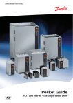
MCD3000 Series
■ Warnings ............................................................ 2
Section 4.0
■ Programming
4.1 Programming Procedure ............................... 17
4.2 Programmable Functions ............................... 17
Section 5.0
■ Operation
5.1 Local Control Panel .......................................
5.2 Remote Control .............................................
5.3 Serial Communications ..................................
5.4 Restart Delay .................................................
5.5 Secondary Parameter Set ..............................
5.6 Motor Thermal Model ....................................
5.7 Pre-start Tests ...............................................
5.8 Operation After Power Loss ...........................
29
30
30
30
30
30
30
30
■ Specifications
6.1 General Technical Data ..................................
6.2 Current Ratings .............................................
6.3 Power Termination Details .............................
6.4 Semi-conductor Fuses ..................................
6.5 Dimensions/Weights ......................................
31
32
33
33
34
■ Design Guide
7.1 Reduced Voltage Starting ..............................
7.2 Types Of Soft Start Control ............................
7.3 MCD3000 Control Principles .........................
7.4 Understanding Soft Starter Ratings ...............
7.5 Model Selection .............................................
7.6 Typical Applications .......................................
7.7 Power Factor Correction ...............................
7.8 Line Contactors .............................................
7.9 Soft Braking ..................................................
35
36
36
37
37
39
40
40
40
■ Fault Procedure
8.1 Trip Codes ....................................................
8.2 Trip Log .........................................................
8.3 General Faults ...............................................
8.4 Tests and Measurement Procedures .............
42
44
44
45
Section 6.0
Section 7.0
Section 8.0
■ Quick Set-up .................................................... 3
■ Description ....................................................... 4
■ Installation
3.1 Mechanical Installation ..................................... 6
3.2 Ventilation ........................................................ 6
3.3 General Layout ................................................ 6
3.4 Power Wiring - Standard Connection ............... 7
3.5 Power Wiring - Bypass Connection .................. 7
3.6 Power Wiring - D.C.Brake Connection .............. 8
3.7 Power Wiring – Inside Delta Connection ........... 8
3.8 Control Supply Voltage .................................... 9
3.9 Control Wiring ................................................. 9
3.10 Motor Thermistors ....................................... 10
3.11 Control Circuit Examples ............................. 10
3.12 Serial Communications ................................ 12
MG.15.A4.22 - VLT is a registered Danfoss trademark
1
Contents
Section 0.0
Section 1.0
Section 2.0
Section 3.0
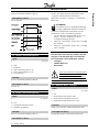
Warnings
MCD3000 Series
The MCD3000 contains dangerous
voltages when connected to line voltage.
Only a competent electrician should carry
out the electrical installation. Improper installation of
the motor or the MCD3000 may cause equipment
failure, serious injury or death. Follow this manual and
®
National Electrical Codes (NEC ) and local safety
codes.
■ Safety regulations
1. The soft starter must be disconnected from the
mains if repair work is to be carried out.
2. The [STOP] on the control panel of the soft starter
does not disconnect the equipment from the
mains and thus is not to be used as a safety
switch.
It is the responsibility of the user or the
person installing the MCD3000 to provide
proper grounding and branch circuit
protection according to the National Electric Code
®
(NEC ) and local codes.
■ Warning against unintended start
1. The motor can be brought to a stop by means of
digital commands, bus commands or a local stop,
while the soft starter is connected to the mains.
If personal safety considerations make it
necessary to ensure that no unintended start
occurs, these stop functions are not sufficient.
2. A motor that has been stopped may start if faults
occur in the electronics of the soft starter, or if the
soft starter’s Auto Reset function has been
activated and a temporary fault in the supply
mains or the motor connection ceases.
Indicates a high voltage warning
■ Avoiding soft starter damage
Please read and follow all instructions in this manual.
Additionally, take special note of the following:
1. Do not connect power factor correction
capacitors to the soft starter output. Static power
factor correction, if used, must be connected on
the mains side of the soft starter.
2. Do not apply voltage to the MCD3000 control
inputs. The inputs are active 24 VDC and must be
controlled with potential free circuits.
3. When installed in non-ventilated enclosures, soft
starters should be used with a bypass contactor
to prevent excessive enclosure temperatures.
4. When bypassing a soft starter take care to ensure
phase connections are correct. i.e. B1-T1, L2-T2,
B3-T3.
5. When using the D.C.Brake function ensure the
D.C.Braking contactor is connected across output
terminals T2-T3 only and that it operates only
when the braking function is operating. Incorrect
connection or operation will cause soft starter
damage.
Electrostatic Precaution; Electrostatic
discharge (ESD). Many electronic
components are sensitive to static
electricity. Voltages so low that they cannot be felt,
seen or heard, can reduce the life, affect performance,
or completely destroy sensitive electronic
components. When performing service, proper ESD
equipment should be used to prevent possible
damage from occurring.
■ Symbols used in this manual
When reading this manual you will come across
different symbols that require special attention. The
symbols used are the following:
Indicates something to be noted by the
reader
Indicates a general warning
2
MG.15.A4.22 - VLT is a registered Danfoss trademark
MCD3000 Series
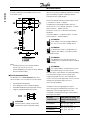
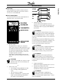
To program the MCD3000 with the motor FLC do the
following:
1. Enter the programming mode by pressing the
[MENU/CANCEL] button on the Local Control
Panel. The display will show the number of the
first programming parameter, Par.1 Motor FLC
2. Press the [CHANGE DATA/OK] button to display
the programmed value. The setting may now be
adjusted.
3. Using the [+/-] buttons adjust the setting to match
the motor FLC.
4. When correct, store the Motor FLC setting by
pressing the [CHANGE DATA/OK] button
(Pressing the [MENU/CANCEL] button returns you
to the parameter number without saving the new
value).
5. Return the MCD3000 to run mode by pressing the
[MENU/CANCEL] button.
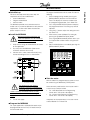
■ Install the MCD3000
Mounting, wiring and setting the soft
starter into operation must be carried out
properly by trained personnel.
1.
2.
3.
Verify that the ratings of the MCD3000 are correct
for the application.
Physically install the MCD3000. (Refer to the
Installation section of this manual)
Connect mains, motor, motor thermistor (if any)
and control voltage circuits as shown below.
■ Start the motor
With the motor FLC programmed, the motor can now
be started using the MCD3000 [START] button.
The voltage of the soft starter is
dangerous whenever the equipment is
connected to the mains. Ensure the soft
starter is correctly connected and that all safety
measures have been taken before switching on the
supply.
4.
Turn on the supply.
Other commonly used functions that may be useful in
a Quick Set-up situation include:
• Par. 5 Soft Stop (Refer to the Programming
section of this manual for a description)
• Par. 2 Current Limit (Refer to the Programming
section of this manual for a description)
If required, set these parameters in the same manner
as described for Par 1. Motor FLC
■ Program the MCD3000
For simple applications the MCD3000 needs only to
be programmed with the FLC (Full Load Current) of
the connected motor.
MG.15.A4.22 - VLT is a registered Danfoss trademark
3
Quick Set-up
■ Quick Set-up
For basic start/stop control only three steps are
required to commission the MCD3000.
• Install the MCD3000
• Program the MCD3000
• Start the motor.
The MCD3000 provides many other features that
enable users to customise operation for their particular
requirements. To learn more about these features
please study this manual.
Description
MCD3000 Series
■ Description
The Danfoss MCD3000 Soft Starter is an advanced
electronic motor starting system. It performs four main
functions;
1. Start control.
2. Stop control, including both soft stop (extended
stop time) and braking (reduced stop time).
3. Electronic motor protection.
4. Monitoring & system interface.
Models MCD3007 - 3132 are IP21 (NEMA 1) rated
and have a local control panel that includes start, stop
& reset push buttons. They are suitable for wall
mounting, or installation in a switchboard.
Models MCD3185 - 3800 have an IP20 rating and
must be installed in a switchboard or other enclosure.
The MCD3000 Soft Starters are complete and require
no optional modules to add functionality.
Automatic detection and calibration for supply voltage
and frequency eliminates the need for special models.
MCD3000 Soft starters are available with two
maximum voltage ratings.
•
■ Ordering type code
MCD 3
-
-
-
2SQMREP1SXSVO;$:
e.g. 55kW = 3055
185kW = 3185
1E\MQYQ:SPXEKI6EXMRK
e.g. T5 = 525 VAC
T7 = 690 VAC*
)RGPSWYVI
B21 = Bookstyle IP21
C20 = Compact IP20
C21 = Compact IP21
'SRXVSP7YTTP]:SPXEKI
CV2 = 110 VAC & 230 VAC
* UL & C-UL approval for T7 models is applicable
where the supply voltage is 600V or less.
200 VAC ~ 525 VAC
1'(
1SHIP
MCD3007
MCD3015
MCD3018
MCD3022
MCD3030
MCD3037
MCD3045
MCD3055
MCD3075
MCD3090
MCD3110
MCD3132
MCD3185
MCD3220
MCD3300
MCD3315
MCD3400
MCD3500
MCD3600
MCD3700
MCD3800
4
• 200 VAC ~ 690 VAC
The power circuit uses reverse parallel connected
thyristors to provide full wave control on all three
phases. The MCD3000 can be used with or, if local
regulations permit, without a line contactor.
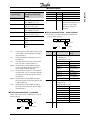
6EXIH'YVVIRX%QTW
%'E
20
34
39
47
68
86
93
121
138
196
231
247
364
430
546
630
775
897
1153
1403
1564
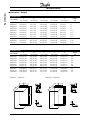
(MQIRWMSRWQQMRGLIW
,IMKLX
;MHXL
(ITXL
530 (20.87)
132 (5.20)
270 (10.63)
530 (20.87)
132 (5.20)
270 (10.63)
530 (20.87)
132 (5.20)
270 (10.63)
530 (20.87)
132 (5.20)
270 (10.63)
530 (20.87)
132 (5.20)
270 (10.63)
530 (20.87)
132 (5.20)
270 (10.63)
530 (20.87)
132 (5.20)
270 (10.63)
530 (20.87)
132 (5.20)
270 (10.63)
530 (20.87)
264 (10.40)
270 (10.63)
530 (20.87)
264 (10.40)
270 (10.63)
530 (20.87)
264 (10.40)
270 (10.63)
530 (20.87)
396 (15.60)
270 (10.63)
850 (33.46)
430 (16.93)
280 (11.02)
850 (33.46)
430 (16.93)
280 (11.02)
850 (33.46)
430 (16.93)
280 (11.02)
850 (33.46)
430 (16.93)
280 (11.02)
850 (33.46)
430 (16.93)
280 (11.02)
850 (33.46)
430 (16.93)
280 (11.02)
1000 (39.37)
560 (22.05)
315 (12.40)
1000 (39.37)
560 (22.05)
315 (12.40)
1000 (39.37)
560 (22.05)
315 (12.40)
4VSXIGXMSR
*SVQEX
IP21 Book style (B21)
IP21 Book style (B21)
IP21 Book style (B21)
IP21 Book style (B21)
IP21 Book style (B21)
IP21 Book style (B21)
IP21 Book style (B21)
IP21 Book style (B21)
IP21 Compact (C21)
IP21 Compact (C21)
IP21 Compact (C21)
IP21 Compact (C21)
IP20 Compact (C20)
IP20 Compact (C20)
IP20 Compact (C20)
IP20 Compact (C20)
IP20 Compact (C20)
IP20 Compact (C20)
IP20 Compact (C20)
IP20 Compact (C20)
IP20 Compact (C20)
MG.15.A4.22 - VLT is a registered Danfoss trademark
MCD3000 Series
Function
Starting
• Current Limit
• Current Ramp
• Torque Boost
• Torque Control
Stopping
• Soft Stop
• Pump Control
• D.C. Brake
Protection
• Motor Overload
• Phase Imbalance
• Undercurrent
• Instantaneous Overload
• Phase Rotation
• Restart Delay
• Motor Thermistor
• Power Circuit Tests
• Shorted SCR
• Starter Heatsink Overtemperature
• Supply Frequency
• RS485 Comms Error
Interface
• Local Control Panel
• Remote Inputs
• Serial Communications (RS485)
• Programmable Relay Outputs
Sundry
• Password Protection
• Dual Parameter Set
• Trip Log
• High & Low Current Flags
• Automatic Reset
•
•
•
•
Current Display
Motor Temperature Display
Reset parameters to default
settings
Program starter via serial link
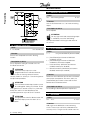
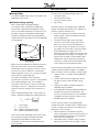
■
Electrical Schematic
Description
■ Functions
Related
Parameters
2
3&4
16
16
5
17
18 & 19
6
7, 12 & 31
8, 13 & 32
9, 14 & 33
11
15
24
20
20
22, 23 & 24
36, 37 & 38
46, 47 & 48
25 - 33
45
34 & 35
39, 40, 41 &
42
49
-
MG.15.A4.22 - VLT is a registered Danfoss trademark
5
Installation
MCD3000 Series
■ Mechanical installation
Models MCD3007~3132 have an IP21 rating and can
be wall mounted or installed inside another enclosure.
These models can be mounted side by side with no
clearance.
Models MCD3185~3800 have an IP20 rating and
must be mounted in another enclosure. These models
must have a clearance of 100mm on either side.
through the enclosure to limit heat rise in the
enclosure.
The table below shows airflow requirements for
selected motor currents.
Motor
Amps
10
20
30
40
50
75
100
125
150
175
200
250
300
350
400
450
500
550
600
Heat
(watts)
45
90
135
180
225
338
450
563
675
788
900
1125
1350
1575
1800
2025
2250
2475
2700
3
Required Airflow m /min
o
o
5 C Rise
10 C Rise
0.5
0.2
0.9
0.5
1.4
0.7
1.8
0.9
2.3
1.1
3.4
1.7
4.5
2.3
5.6
2.8
6.8
3.4
7.9
3.9
9.0
4.5
11.3
5.6
13.5
6.8
15.8
7.9
18.0
9.0
20.3
10.1
22.5
11.3
24.8
12.4
27.0
13.5
ATTENTION
If other heat sources are installed in an
enclosure with the MCD3000, this heat must
also be considered when calculating required airflow.
ATTENTION
If the MCD3000 is installed in an enclosure
without ventilation a bypass contactor should
be employed to prevent heat dissipation during run.
■ General layout
ATTENTION
Do not mount in direct sunlight or near heat
radiating elements.
■ Ventilation
MCD3000 cooling is by means of air circulation.
Consequently, the air needs to be able to move freely
above and below the soft starter.
Soft starters dissipate approximately 4.5 watts per
amp. When installing a soft starter in a switchboard or
other enclosure, ensure there is sufficient airflow
6
MG.15.A4.22 - VLT is a registered Danfoss trademark
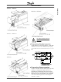
MCD3000 Series
Installation
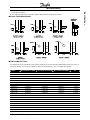
MCD3007 ~ MCD3055
MCD3185 ~ MCD3800
MCD3075 ~ MCD3110
Use cables complying with local
regulations.
■ Power wiring - Standard connection
Supply voltage must be connected to the starter input
terminals L1, L2 & L3. The motor terminals must be
connected to the soft starter output terminals T1, T2 &
T3.
MCD3132
■ Power wiring - Bypass connection
A bypass contactor may be used to bypass the starter
during run. A separate set of power terminals is
provided within the MCD3000 for connection of the
bypass contactor. These bypass terminals enable the
MCD3000 to continue to provide all motor protection
and current monitoring functions when the bypass
contactor is closed.
MG.15.A4.22 - VLT is a registered Danfoss trademark
7
Installation
MCD3000 Series
Either Relay Output C or Relay Output A can be
programmed to control operation of the bypass
contactor.
Par. 36 Relay A - Function Assignment = 1 (Run)
Par. 38 Relay C - Function Assignment = 0 (Run)
Failure to correctly connect the bypass
contactor (B1-T1, L2,-T2, & B3-T3) will
result in a loss of current based protection
systems possibly leading to a motor failure.
Failure to correctly connect the bypass
contactor (B1-T1, L2,-T2, & B3-T3) may
result in a phase to phase short circuit
causing severe equipment failure .
operating, or if the .D.C.Brake contactor is incorrectly
connected between T1-T2 or T1-T3.
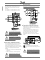
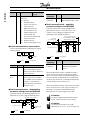
■ Power wiring – Inside delta connection
Models MCD3185 ~ MCD3800 can be connected
inside the delta circuit of the motor when fitted with an
optional Inside Delta Kit.
Soft starters connected within the delta circuit of a
motor control only phase current thereby enabling
them to be used with larger motors than would be
possible with normal line connection. See the
Specifications section of this manual for inside delta
ratings.
K1M
L1
T1
U1
L1B
3 PHASE
SUPPLY
L2
T2
L2B
L3
■ Power wiring - D.C.Brake connection
If the D.C.Braking function is to be used, a contactor
must be wired to short output terminals T2 & T3
during the braking operation. This contactor must be
controlled by the MCD3000 Relay Output C and Relay
Output C must be programmed for D.C.Brake
operation.
• Refer to Par. 18 and 19 for D.C.Brake parameter
adjustments.
• Refer Par. 38 Relay C - Function Assignment.
Legend
K1M
Line Contactor
T3
U2
V1
V2
W1
W2
Motor
L3B
E
ATTENTION
For inside delta connection to be possible
both ends of all three motor windings must be
accessible.
When utilizing the inside delta connection
method voltage remains connected to one
end of the motor windings even when the
soft starter is in the off or tripped state. A
The MCD3000 power modules will be
damaged if the D.C.Brake contactor is
closed when the D.C.Brake function is not
8
MG.15.A4.22 - VLT is a registered Danfoss trademark
MCD3000 Series
When fitted with one of the kits from the following
table, MCD3000 units are inside delta capable. The
inside delta capability is additional to all normal
functionality and is totally automatic. No user
adjustment or settings are required.
MCD3000 Model
MCD3185
MCD3220
MCD3300
MCD3315
MCD3400
MCD3500
MCD3600
MCD3700
MCD3800
Inside Delta Kit
175G3043
175G3044
175G3045
175G3046
175G3047
175G3048
175G3049
175G3050
175G3051
protection.
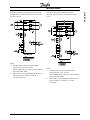
■ Control wiring
The MCD3000 can be controlled using the local push
buttons, or via remote control inputs. Switch between
the local and remote modes using the
[LOCAL/REMOTE] push button.
The MCD3000 has four remote control inputs.
Contacts used for controlling these inputs should be
low voltage, low current rated (Gold flash or similar).
The Stop and Reset circuits must be closed for
the MCD3000 to run in remote control mode.
Push button control example:
■ Control Supply Voltage
Voltage must be connected to the starter control
voltage terminals. Control voltage can be either 230
VAC or 400 VAC (CV4)
110 VAC (+10% / -15%)
or 230 VAC (+10% / -15%)
MCD3000 Model
MCD3007~MCD3022
MCD3030~MCD3055
MCD3075~MCD3110
MCD3132~MCD3500
MCD3600~MCD3800
{
{
A1
A3
Maximum VA
10VA
17VA
23VA
40VA
55VA
The following range of auto-transformers are available
as optional accessories and can be fitted within the
MCD3000 where other control voltages must be used.
Input Voltage
110 VAC / 460 VAC
110 VAC / 575 VAC
24 VAC / 110 VAC
Two wire control example:
Electronics
A2
Supply
Part Number
MCD3007 ~
MCD3075 ~
MCD3055
MCD3800
175G5084
175G5144
175G5085
175G5145
175G5087
175G5146
Removing control voltage from the
MCD3000 resets the motor overload
MG.15.A4.22 - VLT is a registered Danfoss trademark
ATTENTION
Simultaneously pressing the [STOP] and
[RESET] buttons causes the MCD3000 to
immediately remove voltage from the motor resulting in
a coast to stop. Any soft stop or D.C.Brake settings
are ignored.
Do not apply voltage to the control inputs.
The inputs are active 24 VDC and must
be controlled with potential free circuits.
The Par. Set input determines which of the two
MCD3000 motor parameter sets is operative. When a
start is initiated the MCD3000 checks the state of the
9
Installation
line contactor or shunt trip activated circuit breaker
must be used to totally isolate the motor in the event
of a fault condition.
Installation
MCD3000 Series
Par. Set input. If there is an open circuit the primary
parameters (Par. 1 - 9) are operative. If there is a
closed circuit the secondary parameters (Par. 25 - 33)
are operative.
■ Control circuit examples
Example 1. A basic installation where motor operation
is controlled using the MCD3000 Local Control Panel.
The MCD3000 provides three relay outputs.
13
14
Output A
21
22
Output B
24
33
34
Output C
Line contactor
Run
High current flag
Low current flag
Trip
Output on
High current flag
Low current flag
Line contactor
Run
D.C.Brake contactor
All outputs are programmable. Refer Par. 36, 37 & 38
Relay Function Assignment.
Notes:
1. The MCD3000 must be in local mode to function
with this circuit. Use the [LOCAL/REMOTE] push
button to switch between local and remote
modes.
■ Motor thermistors
If the motor is fitted with thermistors these may be
connected directly to the MCD3000. A trip will occur if
the thermistor circuit resistance is above
approximately 2.8kΩ.
If thermistors are not connected to the MCD3000
there must be a link across the thermistor input
terminals.
10
MG.15.A4.22 - VLT is a registered Danfoss trademark
MCD3000 Series
Notes:
1. The MCD3000 must be in remote mode to
function with this circuit. Use the
[LOCAL/REMOTE] push button to switch between
local and remote modes.
2. Relay Output A must be programmed for the Line
Contactor function. Refer Par. 36 Relay A Function Assignment.
MG.15.A4.22 - VLT is a registered Danfoss trademark
Example 3. MCD3000 installed with a bypass
contactor and controlled via a remote push button
circuit.
Installation
Example 2. MCD3000 installed with a line contactor
and operated via a remote two wire start circuit with
reset push button.
Notes:
1. The MCD3000 must be in remote mode to
function with this circuit. Use the
[LOCAL/REMOTE] push button to switch between
local and remote modes.
2. Relay Output C must be programmed for the Run
function. Refer Par. 38 Relay C - Function
Assignment.
11
Installation
MCD3000 Series
Example 4. MCD3000 controlled by remote 3 wire
push button circuit.
Where this cannot be avoided consideration should be
given to providing magnetic shielding to reduce
induced common mode voltages.
Data transmitted to and from the MCD3000 must be
in 8 bit ASCII, no parity, 1 stop bit.
The MCD3000 can be programmed to trip if the
RS485 link fails. This is done by setting Par. 24 Serial
Communications - RS485 Time Out.
Baud rate is set by Par. 22 Serial Communication Baud Rate.
The starter address is assigned using Par. 23 Serial
Communications - Satellite Address.
ATTENTION
Slave address must be two digit, addresses
less than 10 must have a leading zero (0).
ATTENTION
If no MCD3000 starter is configured to the
specific slave address, no response will be
received by the host.
Notes:
1. The MCD3000 must be in remote mode to
function with this circuit. Use the
[LOCAL/REMOTE] push button to switch between
local and remote modes.
■ Serial communications
The MCD3000 has a non-isolated RS485 serial
communications link. The serial link can be used to;
•
•
•
•
Control MCD3000 operation
Query MCD3000 status and operating data
Read (download) MCD3000 parameter settings
Program (upload) MCD3000 parameters
ATTENTION
The MCD3000 may take up to 250ms to
respond. The host software timeout should be
set accordingly.
ATTENTION
The satellite address and baud rate may also
be altered through the serial interface.
Behaviour of the serial interface will not be affected by
such parameter changes until the current Serial
Programming mode session is terminated by the
master. The serial master application must ensure that
altering these parameters does not cause
communication problems.
The details of the message fragments used in
communicating with the MCD3000 are shown in the
table below. The message fragments may be
assembled into complete messages as described in
the sections that follow.
Message
Fragment Type
ATTENTION
Communications cabling should not be
located within 300mm of power cabling.
Send Address
Send Command
Send Request
Read Parameters
12
ASCII Character String or
(Hexidecimal Character
String)
EOT [nn] [lrc] ENQ or
(04h [nn] [lrc] 05h)
STX [ccc] [lrc] ETX or
(02h [ccc] [lrc] 03h)
MG.15.A4.22 - VLT is a registered Danfoss trademark
MCD3000 Series
ASCII Character String or
(Hexidecimal Character
String)
Write Parameters
Receive Data
Receive Status
Parameter Number
Parameter Value
ACK
NAK
ERR
STX [dddd] [lrc] ETX or
(02h [dddd] [lrc] 03h)
STX [ssss] [lrc] ETX or
(02h [ssss] [lrc] 03h)
DC1 [pppp] [lrc] ETX
(011h [pppp] [lrc] 03h)
DC2 [vvvv] [lrc] ETX
(012h [vvvv] [lrc] 03h)
ACK or
(06h)
NAK or
(15h)
BEL
(07h)
Command
Start
Stop
Reset
Coast to stop
two byte ASCII number representing the soft
starter address where each decimal digit is
represented by n.
lrc =
two byte longitudinal redundancy check in
hexadecimal.
ccc = three byte ASCII command number where
each character is represented by a c.
dddd = four byte ASCII number representing the
current or temperature data where each
decimal digit is represented by d.
ssss= four byte ASCII number. The first two bytes
are ASCII zero. The last two bytes represent
the nibbles of a single byte of status data in
hexadecimal.
pppp = four byte ASCII number representing the
parameter number where each decimal digit
is represented by p.
vvvv = four byte ASCII number representing the
parameter value where each decimal digit is
represented by v.
Send
Address
= Master
NAK
Invalid LRC
Send
Request
= Master
Receive
Data
NAK
Invalid LRC
= Slave (MCD3000)
Request ASCII Bit No.
Status
C10
Status_1
C12
Version
C16
Send
Command ACK
Possible error responses
ACK
Possible error responses
■ Serial communications - commands
Commands can be sent to the MCD3000 using the
following format;
ACK
Comment
Initiates a start.
Initiates a stop
Resets a trip state
Initiates an immediate
removal of voltage from the
motor. Any soft stop or
D.C.Brake settings are
ignored.
■ Serial communications – status retrieval
Starter status can be retrieved from the MCD3000
using the following format;
nn =
Send
Address
ASCII
B10
B12
B14
B16
Receive Data
(ssss)
Requests the configuration status of
the MCD3000.
(Positive logic 1 = true)
Status.0
Unallocated
Status.1
Unallocated
Status.2
Unallocated
Status.3
Positive phase
rotation
Status.4
Soft stopping
Status.5
Unallocated
Status.6
60Hz operation
Status.7
50Hz operation
Requests the operational status of
the MCD3000.
(Negative logic 0 = true)
NOT Status._1.0
Power On
NOT Status._1.1
Output On
NOT Status._1.2
Run
NOT Status._1.3
Overload
NOT Status._1.4
Restart delay
NOT Status._1.5
Unallocated
NOT Status._1.6
Unallocated
NOT Status._1.7
Unallocated
RS485 protocol version number.
= Slave (MCD3000)
MG.15.A4.22 - VLT is a registered Danfoss trademark
13
Installation
Message
Fragment Type
Installation
MCD3000 Series
Request ASCII Bit No.
Receive Data
(ssss)
Requests the trip status of the
MCD3000.
255= No Trip
0= Shorted SCR trip
1= Excess start time trip
2= Overcurrent trip
3= Motor thermistor trip
4= Phase imbalance trip
5= Supply frequency trip
6= Phase rotation trip
7= Instantaneous overload trip
8= Power circuit fault
9= Undercurrent trip
10= Starter overtemperature trip
Trip Code C18
■ Serial communications –data retrieval
Data can be retrieved from the MCD3000 using the
following format;
Send
Address
Send
Request
ACK
Possible error responses
= Master
Request
Current
ASCII
D10
Tempera
ture
D12
NAK
Invalid LRC
= Slave (MCD3000)
Receive Data (dddd)
Requests motor current. The
data is 4 byte decimal ASCII.
Minimum value 0000, Maximum
value 9999 Amps.
Requests the calculated value
of the motor thermal model as
a % of Motor Thermal Capacity.
The data is 4 byte decimal
ASCII. Minimum value 0000%.
Trip point 0105%.
parameter settings from the MCD3000
Parameter settings may be downloaded from the
MCD3000 at any time using the following format;
Repeat until master sends NAK
ACK
Read
Par.
ACK
Par. No
Par. Value NAK
NAK
Invalid
LRC
NAK
Possible error responses
ERR
= Master
14
Invalid parameter
number
ASCII
P10
Comment
Readies MCD3000 to
download parameter values.
■ Serial communications – uploading
parameter settings to the MCD3000
Parameter adjustments may be uploaded to the
MCD3000 only when it is in the off state i.e. not
starting, running, stopping or tripped. Use the
following format to upload parameters;
Exit serial programming mode
and store parameters to EEPROM
Enter serial
programming mode
Send
Address
ACK
Repeat until master sends NAK
Write
Par.
ACK
Par. No
ACK
Par. Value
NAK
Invalid
LRC
NAK
Invalid
LRC
Par.
Value
NAK
NAK
Possible error responses
Receive
Data
■ Serial communications – downloading
Send
Address
Read
Parameters
Download
Parameters
= Master
Write
Parameters
Upload
Parameters
ERR
ERR
ERR
Unable to program
(motor running)
Invalid Par No.
Par. value out
of range
= Slave (MCD3000)
ASCII
P12
Comment
Readies the MCD3000 for
uploading of parameter
values
When the MCD3000 receives a Upload Parameters
command it enters the Serial Programming mode.
When in the Serial Programming mode the MCD3000
local push buttons and remote inputs are inoperative,
the serial start command is unavailable and MCD3000
numeric display flashes the letters ‘SP’.
When the Upload Parameters command is terminated
by the master or with an error or with a timeout, the
parameters are written to the EEPROM and the
MCD3000 exits the Serial Programming mode.
ATTENTION
The Serial Programming mode will timeout in
500ms if there has been no serial activity.
ATTENTION
The following parameters may not be
adjusted, Par 43, 44, 45, 46 & 49. If values for
= Slave (MCD3000)
MG.15.A4.22 - VLT is a registered Danfoss trademark
MCD3000 Series
■ Serial communications – calculating the
check sum (LRC)
Each command string sent to and from the MCD3000
includes a check sum. The form used is the
Longitudinal Redundancy Check (LRC) in ASCII hex.
This is an 8-bit binary number represented and
transmitted as two ASCII hexadecimal characters.
To calculate LRC:
1. Sum all ASCII bytes
2. Mod 256
3. 2’s complement
4. ASCII convert
STX
[d1]h
[d2]h
[d3]h
[d4]h
LRC1
LRC2
ETX
Installation
these parameters are uploaded to the MCD3000 there
will be no effect and no error generated.
d1 = 30h
d2 = 30h
d3 = 30h plus upper nibble of status byte right
shifted by four binary places.
d4 = 30h plus lower nibble of status byte.
For example status byte = 1Fh, response is
STX
30h
30h
31h
46h
LRC1
LRC2
ETX
For example Command String (Start);
ASCII
STX
B
1
0
or
02h
42h
31h
30h
ASCII
Hex
Binary
STX
02h
0000 0010
B
42h
0100 0010
1
31h
0011 0001
0
30h
0011 0000
A5h
1010 0101
SUM (1)
A5h
1010 0101
MOD 256 (2)
5Ah
0101 1010
1’s COMPLEMENT
01h
0101 1011
+1=
5Bh
0101 1011
2’s COMPLEMENT (3)
ASCII
5
B
ASCII CONVERT (4)
or
35h
42h
LRC CHECKSUM
The complete command string becomes
ASCII
STX
B
1
0
5
B
ETX
or
02h
42h
31h
30h
35h
42h
03h
To verify a received message containing an LRC;
1. Convert last two bytes of message from ASCII to
binary.
nd
2. Left shift 2 to last byte 4 bits.
3. Add to last byte to get binary LRC.
4. Remove last two bytes from message.
5. Add remaining bytes of message.
6. Add binary LRC.
7. Round to one byte.
8. The result should be zero.
Response or status bytes are sent from the MCD3000
as an ASCII string.
MG.15.A4.22 - VLT is a registered Danfoss trademark
15
Programming
MCD3000 Series
■ Programming
Number
1
2
3
4
5
6
7
8
9
10
11
12
13
14
15
16
17
18
19
20
21
22
23
24
25
26
27
28
29
30
31
32
33
34
35
36
37
38
39
40
41
42
45
46
47
48
Parameter Name
Motor FLC
Current Limit
Current Ramp - Initial Current
Current Ramp - Ramp Time
Soft Stop Ramp Time
Motor Thermal Capacity
Phase Imbalance Sensitivity
Undercurrent Trip Point
Instantaneous Overload Trip Point
Excess Start Time Protection
Phase Rotation Protection
Phase Imbalance Protection Delay
Undercurrent Protection Delay
Instantaneous Overload Protection Delay
Restart Delay
Torque Enhancement
Soft Stop Profile
D.C.Brake - Brake Time
D.C.Brake - Brake Torque
Local / Remote Mode
Current Gain
Serial Communication - Baud Rate
Serial Communication - Satellite Address
Serial Communication - RS485 Time Out
1)
Motor FLC
1)
Current Limit
1)
Current Ramp - Initial Current
1)
Current Ramp - Ramp Time
1)
Soft Stop Ramp Time
1)
Motor Thermal Capacity
1)
Phase Imbalance Sensitivity
1)
Undercurrent Trip Point
1)
Instantaneous Overload Trip Point
Low Current Flag Set Point
High Current Flag Set Point
Relay A - Function Assignment
Relay B - Function Assignment
Relay C - Function Assignment
Automatic Reset - Trip Types
Automatic Reset - Number Of Resets
Automatic Reset - Reset Delay Group 1&2
Automatic Reset - Reset Delay Group 3
Trip Log
Password
Change Password
Parameter Lock
✭ = factory setting
16
Number
49
50
51
52
53
Parameter Name
Load Default Parameter Settings
Under Frequency Protection Delay
Phase Imbalance Protection Enable
Undercurrent Protection Enable
Expanded Supply Frequency Window
1)
Secondary Parameter Set adjustments
MG.15.A4.22 - VLT is a registered Danfoss trademark
MCD3000 Series
■ Programmable functions
1
Motor FLC
Value:
(Depends On Model) Amps
✭ Depends on Model
Function:
Calibrates the MCD3000 for the Full Load Current of
the motor.
Description of choice:
Set according to motor nameplate Full Load Current.
2
Current Limit
Value:
100% - 550% Motor FLC
To adjust parameters do the following:
✭ 350%
Function:
Sets the desired starting current limit.
Description of choice:
The current limit should be set so that the motor
accelerates easily to full speed.
ATTENTION
Start current must be great enough to allow
the motor to produce sufficient torque to
accelerate the connected load. The minimum current
required to do this is dependent on motor design and
load torque requirements.
3
Current Ramp - Initial Current
Value:
10% - 550% Motor FLC
✭ 350%
Function:
✭ = factory setting
MG.15.A4.22 - VLT is a registered Danfoss trademark
17
Programming
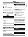
■ Programming procedure
Parameter adjustments are made using the Local
Control Panel. Adjustments can only be made
while the MCD3000 is stopped. When the
MCD3000 is in programming mode the three LEDs to
the right of the numeric display are illuminated.
Programming
MCD3000 Series
Sets the initial starting current for the Current Ramp
start mode. See also parameter 4.
2.
Description of choice:
See parameter 4.
4
Current Ramp - Ramp Time
Value:
1 - 30 seconds
✭ 1 second
Function:
Sets the ramp time for the Current Ramp start mode.
Description of choice:
The Current Ramp start mode modifies the Current
Limit start mode by adding an extended ramp.
Typically the Current Ramp start mode would be used
in two circumstances.
1. For applications where start conditions vary
between starts the Current Ramp mode provides
an optimum soft start irrespective of motor
loading e.g. A conveyor that may start loaded or
unloaded.
In this case make the following settings.
• Set Parameter 2 Current Limit so that the
motor can accelerate to full speed when fully
loaded.
• Set Parameter 3 Current Ramp - Initial
Current so that the motor can accelerate
when unloaded.
• Set Parameter 4 Current Ramp - Ramp Time
according to the desired start performance.
(Very short ramp time settings will result in
higher than necessary start current for
unloaded starts. Very long ramp time settings
may cause starting delays for loaded starts).
✭ = factory setting
18
5
On generator set supplies where a gradual
increase in current is required to allow greater
time for the generator set to respond to the
increased loading.
In this case make the following settings.
• Set Parameter 2 Current Limit as desired.
• Set Parameter 3 Current Ramp - Initial
Current to a lower level than the Current Limit.
• Set Parameter 4 Current Ramp - Ramp Time
to achieve the desired gradual draw of start
current.
Soft Stop Ramp Time
Value:
0 - 100 seconds
✭ 0 seconds (Off)
Function:
Sets the time of the soft stop ramp. The soft stop
function extends motor deceleration time by ramping
down voltage supplied to the motor when a stop is
initiated.
Description of choice:
Set the ramp time to optimise stopping characteristics
for the load.
The MCD3000 soft stop function has two modes,
standard and enhanced pump control. The enhanced
pump control mode can offer superior performance in
some pumping applications. Refer Par. 17 Soft Stop
Profile.
ATTENTION
The MCD3000 soft stop function automatically
determines the step-down voltage setting, no
user adjustment is required.
ATTENTION
The Soft Stop and D.C.Brake functions cannot
be used together. Setting a soft stop ramp
time greater than 0 seconds causes Par. 18 D.C.Brake
- Brake Time to be set to 0 seconds and Par. 38 Relay
C - Function Assignment to be set to OFF.
6
Motor Thermal Capacity
Value:
5 - 120 seconds
✭ 10 seconds
Function:
MG.15.A4.22 - VLT is a registered Danfoss trademark
MCD3000 Series
Description of choice:
The factory setting is adequate for most applications.
When setting the Motor Thermal Capacity two
approaches can be taken.
1. Set according to the Motor DOL time as shown
on the motor data sheet. This makes the full
thermal capacity of the connected motor available
for use. The motor will be allowed to operate up to
its maximum capability during start and when
subjected to operational overloads.
This is ideal when starting high inertia loads or for
applications such as Bandsaws that must ride
through high operating overloads.
ATTENTION
The MCD3000 assumes Direct-On-Line
current to be 600% of motor Full Load
Current. Actual motor DOL current can be accounted
for by using the following formula to calculate the value
of the Motor Thermal Capacity setting.
1 - 4 = Increased sensitivity
5
= Normal sensitivity
6 - 10 = Reduced sensitivity
Programming
Calibrates the MCD3000 motor thermal model for the
connected motors thermal capacity. The Motor
Thermal Capacity is defined as the length of time the
motor can sustain Direct-On-Line current.
Function:
Sets the sensitivity of the imbalance protection.
Description of choice:
Adjust the trip point to accommodate the tolerated
phase imbalance. The factory setting is normally
acceptable but may have to be adjusted to
accommodate individual site variations.
Reaction time of the phase imbalance protection can
also be adjusted. Refer Par. 12 Phase Imbalance
Protection Delay.
ATTENTION
The phase imbalance trip point is desensitised
by 50% during starting and stopping.
8
Undercurrent Trip Point
Value:
15% - 100% Motor FLC
✭ 20 %
Function:
Sets the minimum allowable running current.
2.
Set according to load requirements. While the
Motor Thermal Capacity can safely be set
according to the motor’s published DOL time limit,
some load types do not need this capacity for
starting or riding through overloads while running.
In such circumstances setting the Motor Thermal
Capacity based on what the load requires will
provide an earlier warning of abnormal operation.
To set the Motor Thermal Capacity according to
load requirement, set MCD3000 display to read
motor temperature, run the load, stop and restart
the load while monitoring the calculated motor
temperature. The Motor Thermal Capacity setting
can be reduced until the temperature at the end of
a restart is approximately 80%.
Description of choice:
Where it is desired to stop motor operation on
detection of an abnormally low current, set the
Undercurrent trip point above the motor magnetising
current and below the normal running current.
To defeat the Undercurrent protection function, set the
trip point below the motor’s magnetising current.
Typically < 25%.
Reaction time of the Undercurrent protection can also
be adjusted. Refer Par. 13 Undercurrent Protection
Delay.
Undercurrent protection is disabled during starting and
stopping.
9
7
Phase Imbalance Sensitivity
Value:
1 - 10
✭ 5 (Normal Sensitivity)
✭ = factory setting
MG.15.A4.22 - VLT is a registered Danfoss trademark
Instantaneous Overload Trip Point
Value:
80% - 550% Motor FLC
✭ 400%
Function:
Sets the trip point for the Instantaneous Overload
protection.
19
Programming
MCD3000 Series
Description of choice:
The instantaneous overload trip point should be set to
trip the motor when it begins to stall.
Reaction time of the instantaneous overload protection
can also be adjusted. Refer Par. 14 Instantaneous
Overload Protection Delay.
Instantaneous Overload protection is disabled during
starting and stopping.
10
Excess Start Time Protection
Value:
0 - 255 seconds
✭ 20 seconds
Function:
Sets the maximum allowable start time.
ATTENTION
Ensure the Excess Start Time protection
setting is within the MCD3000 rated capability.
Value:
0-2
✭ 0 (Off)
0 = Off (Forward & Reverse rotation permitted)
1 = Forward Rotation Only
2 = Reverse Rotation Only
Function:
Sets the allowable phase rotation sequence of the
incoming supply.
✭ 3 seconds
Function:
Delays tripping on detection of a phase imbalance
greater than allowed by the Phase Imbalance
Sensitivity setting. (Par. 7 & Par. 31)
Description of choice:
Set to avoid unnecessary tripping due to temporary
phase imbalances.
Undercurrent Protection Delay
Value:
0 - 60 seconds
✭ 5 seconds
Function:
Delays tripping on detection of a motor current lower
than the programmed Undercurrent Trip Point. (Par. 8
& Par. 32)
Description of choice:
Set to avoid unnecessary tripping due to temporary
undercurrent situations.
Undercurrent protection is disabled during starting and
stopping.
14
Phase Rotation Protection
Phase Imbalance Protection Delay
Value:
3 - 254 seconds
13
Description of choice:
Set for a period slightly longer than the normal motor
starting time. The MCD3000 will then trip if the start
time exceeds normal. This provides early indication
that the application conditions have changed or that
the motor has stalled. It can also protect the soft
starter from being operated outside its rated start
capability.
A setting of 0 disables this protection.
11
12
Instantaneous Overload Protection Delay
Value:
0 - 60 seconds
✭ 0 seconds
Function:
Delays tripping on detection of a motor current higher
than the programmed Instantaneous Overload Trip
Point. (Par. 9 & Par. 33)
Description of choice:
Set to avoid unnecessary tripping due to temporary
high overload situations.
Description of choice:
The MCD3000 is itself phase rotation insensitive. This
function allows motor rotation to be limited to one
direction only. Set the protection according to
application requirements.
✭ = factory setting
20
MG.15.A4.22 - VLT is a registered Danfoss trademark
MCD3000 Series
15
Restart Delay
Value:
0 - 254 Units
✭ 1 Unit (10 seconds)
1 Unit = 10 seconds
Function:
Sets the minimum time between the end of a stop and
the beginning of the next start.
Description of choice:
Set according to process requirements. A setting of
zero achieves the minimum restart delay of 1 second).
During the Restart Delay period the LED to the right of
the MCD3000 numeric display will flash, indicating the
motor cannot be started.
16
Torque Enhancement
Value:
0-3
Function:
Selects between soft stop profiles.
Description of choice:
The standard mode is the default soft stop profile and
is appropriate for most installations. In standard mode
motor deceleration is monitored and soft stop
operation is automatically adjusted to optimise
performance.
In addition to the standard mode profile three
specialised pump control modes are available. These
modes provide alternate control algorithms which may
deliver superior performance to the standard mode
depending upon the individual motor and hydraulic
characteristics of the application.
✭ 0 (Off)
0 = Off
1 = Torque boost
2 = Torque control
3 = Torque boost & torque control
Function:
Activates the torque enhancement functions.
Description of choice:
Torque boost provides extra torque at the beginning of
a start. Torque boost can be used for loads that
require high torque to breakaway but then accelerate
freely with lower torque.
ATTENTION
Torque boost results in a fast application of
torque. Ensure that the driven load and drive
chain can handle DOL start torque characteristics.
Torque control provides a more linear application of
torque during start.
17
0 = Standard mode
1 = Pump control (mode 1)
2 = Pump control (mode 2)
3 = Pump control (mode 3)
The D.C.Braking function decreases motor
deceleration time by applying a D.C. current to
the motor terminals when a stop command is
given. This function requires that a contactor
(AC1 rated) be wired between output terminals
T2 & T3 as shown in the electrical schematic
below and that the following MCD3000
parameters be adjusted.
• Par 18. D.C.Brake - Brake Time
• Par 19. D.C.Brake - Brake Torque
• Par 38. Relay C - Function Assignment.
The MCD3000 power modules will be
damaged if the D.C.Brake contactor is
closed when the D.C.Brake function is not
operating. Ensure the D.C.Brake
contactor is controlled by Relay Output C and that
Par. 38 Relay C - Function Assignment is set for
D.C.Braking Contactor Control
The MCD3000 power modules will be
damaged if the D.C.Brake contactor is
incorrectly connected between T1-T2 or
T1-T3.
Soft Stop Profile
Value:
✭ = factory setting
MG.15.A4.22 - VLT is a registered Danfoss trademark
21
Programming
✭ 0 (Standard Mode)
0-3
MCD3000 Series
Programming
19
D.C.Brake - Brake Torque
Value:
30% - 100% Braking Torque
✭ 30%
Function:
Sets the D.C.Brake level as a % of maximum braking
torque.
Description of choice:
Set as required.
ATTENTION
For very high inertia loads more braking torque
is available by use of the ’Soft Braking’
technique described in the Design Guide section of
this manual.
18
D.C.Brake - Brake Time
Value:
0 - 10 seconds
✭ 0 seconds (Off)
Function:
Sets the time of operation of the D.C. Braking
function.
Description of choice:
Set as required. A setting of 0 seconds turns the
D.C.Brake function Off.
ATTENTION
MCD3000 Relay Output C must be
programmed for the D.C.Brake Contactor
Control so that the shorting contactor functions
correctly. Refer Par. 38 Relay C - Function Assignment
for adjustment procedure.
ATTENTION
The D.C.Brake and Soft Stop functions cannot
be used together. Setting a D.C.Brake - Brake
Time greater than 0 seconds causes Par. 5 Soft Stop
Ramp Time and Par.29. Soft Stop Ramp Time
(secondary parameter set) to be set to 0 seconds.
20
Value:
0-3
✭ = factory setting
22
✭ 0 ([LOCAL/REMOTE] button enabled)
0 = [Local/Remote] push button on MCD3000
enabled all the time.
1 = [Local/Remote] push button on MCD3000
enabled only while motor stopped.
2 = Local control only. (MCD3000 push buttons
enabled, remote inputs disabled)
3 = Remote control only. (MCD3000 push buttons
disabled, remote inputs enabled)
Function:
Determines when MCD3000 push buttons and remote
control inputs are operative. Also when, and if, the
[Local/Remote] push button can be used to switch
between local and remote control.
Description of choice:
Set according to desired operational requirements.
21
ATTENTION
During operation of the D.C.Brake function the
MCD3000 display shows the letters ’br’ as
shown below.
Local / Remote Mode
Current Gain
Value:
85% - 115%
✭ 100%
Function:
Adds a gain to the MCD3000 current monitoring
circuits. These circuits are factory calibrated with an
accuracy of ±5%. The gain can be used to match the
MG.15.A4.22 - VLT is a registered Danfoss trademark
MCD3000 Series
ATTENTION
This adjustment affects all current based
functions. e.g. current read-out, motor
overload & all other current based protections and
current outputs.
Description of choice:
The gain should be adjusted according to the following
formula.
22
Serial Communications - RS485 Time Out
Value:
0 - 100 seconds
✭ 0 seconds (Off)
Function:
Sets the maximum allowable period of RS485
inactivity.
Description of choice:
Set this parameter if it is required that a trip should
occur in the event of a failure of RS485
communications with the MCD3000.
A setting of 0 seconds allows the MCD3000 to
continue operating without regular RS485 activity.
ATTENTION
In the event of a RS485 Time Out trip the
MCD3000 cannot be reset until the RS485
communication is resumed. If the RS485
communications cannot be immediately re-established
and temporary manual control is required, Par 24
Serial Communications - RS485 Time Out must be set
to 0 seconds.
Serial Communications - Baud Rate
Value:
1-5
24
✭ 4 (9600 baud)
1 = 1200 baud
2 = 2400 baud
3 = 4800 baud
4 = 9600 baud
5 = 19200 baud
The MCD3000 includes two motor operating
parameter sets. Parameters 25 - 33 make up the
secondary parameter set and replicate the
primary parameter set, Parameters 1 - 9.
Refer to the Operation section of this manual for
detail on enabling the secondary parameter set.
Function:
Sets the baud rate for serial communications.
25
Description of choice:
Set as appropriate.
Motor FLC
(Secondary Parameter Set)
Value:
(Depends On Model)Amps
✭ Depends on Model
See Par. 1 for Function & Description of choice.
23
Serial Communications - Satellite Address
Value:
1 - 99
26
✭ 20
Function:
Assigns the MCD3000 an address for serial
communications.
Description of choice:
Set a unique address number as appropriate.
✭ = factory setting
MG.15.A4.22 - VLT is a registered Danfoss trademark
Current Limit
(Secondary Parameter Set)
Value:
100% - 550% Motor FLC
✭ 350 %
See Par. 2 for Function & Description of choice.
27
Current Ramp - Initial Current
(Secondary Parameter Set)
23
Programming
MCD3000 current read out with an external current
monitoring system.
Programming
MCD3000 Series
Value:
10% - 550% Motor FLC
✭ 350%
See Par. 3 for Function & Description of choice.
28
✭ 1 second
See Par. 4 for Function & Description of choice.
29
Soft Stop Ramp Time
(Secondary Parameter Set)
Value:
0 - 100 seconds
✭ 0 seconds (Off)
See Par. 5 for Function & Description of choice.
30
Motor Thermal Capacity
(Secondary Parameter Set)
Value:
5 - 120 seconds
✭ 10 seconds
Phase Imbalance Sensitivity
(Secondary Parameter Set)
Value:
1 - 10
✭ 5 (Normal Sensitivity)
1 - 4 = Increased sensitivity
5
= Normal sensitivity
6 - 10 = Reduced sensitivity
See Par. 7 for Function & Description of choice.
32
Undercurrent Trip Point
(Secondary Parameter Set)
Value:
15% - 100% Motor FLC
✭ 20 %
Instantaneous Overload Trip Point
(Secondary Parameter Set)
Value:
80% - 550% Motor FLC
✭ = factory setting
24
✭ 400%
✭ 50% Motor FLC
Description of choice:
Set as appropriate.
High Current Flag Set Point
Value:
50 - 550% Motor FLC
✭ 105% Motor FLC
Function:
Sets the current at which the High Current Flag
operates. (High current flags can occur only when the
motor is running).
Relay Output B can be programmed to indicate the
state of the High Current Flag. The relay output will
change state when motor current is above the set
point.
See Par. 37 for Relay B - Function Assignment.
Description of choice:
Set as appropriate.
36
See Par. 8 for Function & Description of choice.
33
Low Current Flag Set Point
Function:
Sets the current at which the Low Current Flag
operates. (Low current flags can occur only when the
motor is running).
Relay Output B can be programmed to indicate the
state of the Low Current Flag. The relay output will
change state when motor current is below the set
point.
See Par. 37 for Relay B - Function Assignment.
35
See Par. 6 for Function & Description of choice.
31
34
Value:
1 - 100% Motor FLC
Current Ramp - Ramp Time
(Secondary Parameter Set)
Value:
1 - 30 seconds
See Par. 9 for Function & Description of choice.
Relay A - Function Assignment
Value:
0-3
✭ 0 (Line contactor)
0 = Line Contactor
1 = Run
2 = High current flag (see Par. 35)
3 = Low current flag (see Par. 34)
Function:
MG.15.A4.22 - VLT is a registered Danfoss trademark
MCD3000 Series
Set to 1 (D.C.Brake Contactor Control) only when
using the D.C.Brake function and make this
adjustment only after first setting Par. 18 D.C.Brake Brake Time.
Description of choice:
Set as required.
ATTENTION
To reduce the chance of equipment damage
through inappropriate adjustment of Relay C
functionality the MCD3000 automatically sets this
parameter to 2 (Off) in the following instances.
• If a soft stop time is programmed while Par. 38.
Relay C - Function Assignment is set to 1
(D.C.Brake Contactor Control).
• When Par. 18 D.C.Brake - Brake Time is changed
to 0 seconds.
• When Par. 18 D.C.Brake - Brake Time is changed
from 0 seconds.
37
Relay B - Function Assignment
Value:
0-4
✭ 0 (Trip)
0 = Trip
1 = Output on
2 = High current flag (see Par. 35)
3 = Low current flag (see Par. 34)
4 = Line contactor
If the start command is still present after a
trip state is reset the motor will be
restarted. Ensure that personal safety is
not at risk from such operation and that all appropriate
safety measures have been taken.
Function:
Sets the functionality of Relay Output B
Description of choice:
See Par. 36
38
39
Automatic Reset - Trip Types
Value:
0-3
Relay C - Function Assignment
Value:
0-2
The Automatic Reset function enables selected
trip types to be automatically reset. Automatic
Reset operation is affected by three settings.
• Trip Types
• Number Of Resets
• Reset Delay
✭ 0 (Run)
✭ 0 (Off)
0 = Off.
1 = Automatically reset Group 1 trips.
2 = Automatically reset Group 1 & 2 trips.
3 = Automatically reset Group 1,2 & 3 trips.
0 = Run
1 = D.C.Brake Contactor Control
2 = Off (does not operate)
Function:
Selects what fault types will be automatically reset.
Function:
Sets the functionality of Relay Output C
Description of choice:
Three groups of trips can be automatically reset.
Description of choice:
✭ = factory setting
MG.15.A4.22 - VLT is a registered Danfoss trademark
25
Programming
Sets the functionality of Relay Output A
Programming
MCD3000 Series
Group
1
2
3
40
Trip Type
Phase Imbalance, Phase Loss
Undercurrent, Instantaneous Overload
Overcurrent, Motor Thermistor
44
Value:
No adjustment
Automatic Reset - Number Of Resets
Value:
1 - 5 Resets
45
✭ 1 Reset
Function:
Sets the number of times faults will be reset before the
trip condition is latched and a manual reset is required.
Description of choice:
Set according to the maximum number of resets
required.
The MCD3000 reset counter will increment by one
when a trip occurs up to the programmed number of
resets. A manual reset will then be required.
The reset counter decrements by one (to a minimum
of zero) after each successful start/stop cycle.
Automatic Reset - Reset Delay Group 1 & 2
Value:
5 - 999 seconds
✭ 5 seconds
Function:
Sets the delay before automatic reset of Group 1 and
Group 2 trips.
Description of choice:
Set as required.
42
Automatic Reset - Reset Delay Group 3
Value:
5 - 60 minutes
✭ 5 minutes
Function:
Sets the delay before automatic reset of Group 3 trips.
Description of choice:
Set as required.
43
Factory Diagnostic Display A
Value:
No adjustment
✭ = factory setting
26
Trip Log
Value:
Read Only
✭ No setting
Function:
Displays the Trip Log. The trip log records the cause of
the last 8 trip events.
Description of choice:
Use the [+/-] buttons to scroll through the trip log.
Refer to the Fault Procedure section of this manual for
a full explanation of the trip log, trip codes and related
fault procedures.
46
41
Factory Diagnostic Display B
Password
Value:
0 - 999
✭0
Function:
Entry of the correct password number does two
things.
1. If the parameter settings are currently in the Read
Only state (Refer Par. 48 Parameter Lock) entering
the correct password number temporarily enables
the Read/Write state allowing parameter settings
to be changed. On exit of the programming mode
parameters return to the Read Only state.
2. Allows access to parameter numbers 47, 48 & 49.
These parameters allow the user to:
• Change the password number
• Change the parameter state between
Read/Write and Read Only thus providing
control over unauthorised changes to
program settings.
• Load the default factory settings.
Description of choice:
Enter the current password number. If the password
number has been lost, contact your Danfoss
representative.
MG.15.A4.22 - VLT is a registered Danfoss trademark
MCD3000 Series
Change Password
Value:
0 - 999
✭0
ATTENTION
If the supply frequency drops below 45Hz
(50Hz supplies) or 55Hz (60Hz supplies) the
MCD3000 will trip instantly irrespective of the delay
setting.
Function:
Sets the password number.
Description of choice:
Set and record the password number as required.
48
Description of choice:
Set to allow continued operation during extreme but
temporary under frequency conditions.
Parameter Lock
Value:
0-1
Function:
Delays tripping on detection of a low supply frequency
when the motor is running, <48Hz (50Hz supplies),
<58Hz (60Hz supplies).
✭ 0 (Read/Write)
51
0 = Read/Write
1 = Read Only
Function:
Enables protection of program settings by restricting
Program Mode functionality to Read Only.
Description of choice:
Set as required.
Value:
0–1
✭ 0 (On)
0 = On
1 = Off
Function:
Activates or defeats the phase imbalance protection.
ATTENTION
When the parameter lock has been changed
from Read/Write to Read Only the new setting
only takes effect once the programming mode has
been exited.
Description of choice:
Set as required.
52
49
Phase Imbalance Protection Enable
Undercurrent Protection Enable
Value:
0–1
Load Default Parameter Values
Value:
0 - 100
✭0
✭ 0 (On)
0 = On
1 = Off
50 = Load default parameter values
Function:
Resets parameter values to factory default settings.
Description of choice:
Set as required.
Description of choice:
Set as required.
50
Function:
Activates or defeats the undercurrent protection.
Under Frequency Protection Delay
Value:
0 – 60 seconds
✭ 0 seconds
✭ = factory setting
MG.15.A4.22 - VLT is a registered Danfoss trademark
27
Programming
47
Programming
MCD3000 Series
53
Expanded Supply Frequency Window
Value:
0–1
✭0
0 = Normal (50Hz window: 48Hz- 52Hz, 60Hz
window 58Hz – 62Hz)
1 = Expanded (50Hz window: 47Hz- 52Hz, 60Hz
window 57Hz – 62Hz)
Function:
Expands the supply frequency window allowed by the
MCD3000 by reducing the lower limit by 1 Hz. This
expansion accommodates power supplies which
suffer long term low frequency situations.
Description of choice:
Apply expansion if required.
✭ = factory setting
28
MG.15.A4.22 - VLT is a registered Danfoss trademark
MCD3000 Series
Operation
■ Operation
Once the MCD3000 has been installed, wired and
programmed according to the instructions earlier in
this manual, it can be operated.
■ Local control panel.
The Local Control Panel can be used to operate the
MCD3000 when in local control mode.
3.
Operational buttons.
Can be used to control operation when the
MCD3000 is in local mode. Switch between local
and remote modes using the [LOCAL/REMOTE]
push button.
ATTENTION
Par. 20 Local / Remote Mode can be set to
prohibit either local or remote mode operation.
If the [LOCAL/REMOTE] button is used in an attempt
to switch to a prohibited mode the numeric display will
show ’OFF’.
Also, operation of the [LOCAL/REMOTE] push button
can be restricted to when the motor is stopped. In this
case pushing the [LOCAL/REMOTE] push button
results in the numeric display showing ’OFF’.
1.
Numeric Display
During operation the display can show either
motor current (Amps) or motor temperature (%) as
calculated by the MCD3000 motor thermal model.
The information being displayed is indicated by
the LEDs to the right of the display, and can be
changed using the [+/-] buttons.
In the event of a trip the display shows the trip
code. Refer to the Fault Procedure section of this
manual.
ATTENTION
If motor current exceeds the maximum current
able to be shown on the numeric display, the
display will show dashes.
--2.
Starter Status LEDs
• Start: Voltage is being applied to the motor
• Run: Full voltage is being applied to the
motor.
• Trip: The starter has tripped.
• Remote: The MCD3000 is in remote control
mode. The local [START],[STOP],[RESET]
push buttons are not operative.
MG.15.A4.22 - VLT is a registered Danfoss trademark
ATTENTION
When control power is applied the MCD3000
may be in either local or remote mode
according to the mode it was in when control power
was removed. The factory setting is local control.
ATTENTION
Simultaneously pressing the [STOP] and
[RESET] buttons causes the MCD3000 to
immediately remove voltage from the motor resulting in
a coast to stop. Any soft stop or D.C.Brake settings
are ignored.
4.
5.
Programming Buttons
Refer to the Programming Section of this manual.
Remote Control Input Status LEDs
Indicate the state of the circuits connected across
the MCD3000 remote control inputs.
ATTENTION
When control power is applied to the
MCD3000, all LEDs and Numeric Display
segments are illuminated for approximately 1 second
to test their operation.
29
Operation
MCD3000 Series
■ Remote control
Remote circuits connected to the MCD3000 control
inputs can be used to operate the starter when in
remote control mode. Refer to the Installation section
of this manual for detail on control wiring options.
■ Serial communication
The RS485 serial link can be used to control operation
when the starter is either local or remote modes.
Programming of the MCD3000 via the serial link is also
possible. Refer to the Installation section of this
manual for detail on serial communications functions.
■ Restart delay
Par. 15 Restart Delay sets a minimum time between
the end of a stop and the beginning of the next start.
During this period the LED to the right of the numeric
display will flash, indicating the motor cannot be
started.
■ Secondary parameter set
The MCD3000 has two motor parameter sets.
• Primary Parameter Set : Par. 1 - 9
• Secondary Parameter Set : Par. 25 - 33
The state of the motor thermal model can be viewed
on the numeric display while the MCD3000 is not in
programming mode. Use the [+/-] keys to change the
parameter shown on the numeric display.
Motor temperature is shown as a % of maximum
temperature. An overload trip occurs at 105%.
■ Pre-start tests
On receiving a start command, MCD3000 starters
operate the Line Contactor relay output (if
programmed) and then perform a series of tests
before applying voltage to the motor terminals and
operating the Output On relay output (if programmed).
■ Operation after power loss
When control and supply voltage is applied to the
MCD3000 it will enter either the local or remote mode
according to the state it was in when voltage was
removed.
If in remote mode, the condition of the remote control
inputs is checked and if a start command is present
the motor will be started.
If in local mode, the motor will not be restarted until
the [START] push button is activated.
When the MCD3000 is in the off state and is
commanded to start, it checks the Par. Set control
input. If open circuit the primary parameter set is used.
If closed circuit the secondary parameter set is used.
ATTENTION
If the start command is given while the
MCD3000 is in the process of stopping (Soft
stop or D.C.Braking) the MCD3000 restarts without
checking the Par. Set control input.
■ Motor thermal model
The MCD3000 motor overload protection is an
advanced motor thermal model. Motor temperature is
continuously calculated by the microprocessor that
uses a sophisticated mathematical model to
accurately reflect motor heat generation and
dissipation during all stages of operation. e.g. Starting,
Running, Stopping & Stopped.
Because it operates continuously, the motor thermal
model eliminates the need for protection systems such
as; Excess Start Time, Limited Starts per hour etc
30
MG.15.A4.22 - VLT is a registered Danfoss trademark
MCD3000 Series
Mains supply (L1, L2, L3):
Supply voltage MCD3000-T5 ..............................................................................................3 x 200 VAC ~ 525 VAC
..................................................................................................... 3 x 200 VAC ~ 440 VAC (Inside Delta Connection)
Supply voltage MCD3000-T7 ............................................................................................. 3 x 200 VAC ~ 690VAC
..................................................................................................... 3 x 200 VAC ~ 440 VAC (Inside Delta Connection)
Supply frequency (at start) ....................................................................................... 50HZ (± 2Hz) / 60 Hz (± 2Hz)
Supply frequency (during start) ........................................................ >45Hz (50Hz supply) or >55Hz (60 Hz supply)
Supply frequency (during run) ......................................................... >48Hz (50Hz supply) or >58Hz (60 Hz supply)
Electronics control voltage ......................................................... 230 VAC (+10%/-15%) or 400 VAC (+10%/-15%)
Control Inputs
Start (Terminals 15 & 16) .................................................................... Normally Open, Active 24 VDC, 8mA approx.
Stop (Terminals 17 & 18) ................................................................. Normally Closed, Active 24 VDC, 8mA approx.
Reset (Terminals 25 & 26) ............................................................... Normally Closed, Active 24 VDC, 8mA approx.
Parameter Set (Terminals 27 & 28) ..................................................... Normally Open, Active 24 VDC, 8mA approx.
Relay Outputs
1)
Programmable Output A (Terminals 13 & 14) ...... Normally Open, 5 A @ 250 VAC/360 VA, 5 A @ 30 VDC resistive
2)
Programmable Output B (Terminals 21, 22 & 24) .... Changeover, 5 A @ 250 VAC/360 VA, 5 A @ 30 VDC resistive
3)
Output C (Terminals 33 & 34) .......................... Normally Open, , 5 A @ 250 VAC/360 VA, 5 A @ 30 VDC resistive
1)
Programmable functions: Line contactor, Run, High current flag, Low current flag
Programmable functions: Tripped, Output on, High current flag, Low current flag, Line contactor
3)
Programmable functions: Run, D.C.Brake Contactor Control, Off
2)
Environmental
Degree of protection MCD3007 to MCD3132 ................................................................................................. IP21
Degree of protection MCD3185 to MCD3800 ................................................................................................. IP20
o
o
Operating Temperatures ..................................................................................................................... -5 C / +60 C
Rated short-circuit current (with semi-conductor fuses) ................................................................................ 100kA
Rated insulation voltage (Surges) .......................................................................... 2 kV line to earth, 1kV line to line
Rated impulse withstand voltage (Fast transients) ............................................................................................. 2 kV
Pollution Degree ........................................................................................................................ Pollution Degree 3
Electro static discharge ......................................................................... 4 kV contact discharge, 8 kV air discharge
Equipment class (EMC) ............................................................................................................................... Class A
Radio-frequency electromagnetic field ...................................................................... 0.15 MHz - 80 MHz: 140dBµV
80 MHz - 1 GHz: 10 V/m
This product has been designed for Class A equipment. Use of the product in domestic environments may cause
radio interference, in which case the user may be required to employ additional mitigation methods.
Standards Approvals
Cá ......................................................................................................................................................... CISPR-11
1
UL ............................................................................................................................................................... UL508
1
C-UL .............................................................................................................................................CSA 22.2 No. 14
CE .................................................................................................................................................. IEC 60947-4-2
1
Requires use of semi-conductor fuses. Excludes models MCD3600~MCD3800
MG.15.A4.22 - VLT is a registered Danfoss trademark
31
Specifications
■ General Technical Data
Specifications
MCD3000 Series
■ Current Ratings
Continuous Ratings (Not bypassed) at 40 C Ambient Temperature, < 1000 metres N
o
Model
MCD3007
MCD3015
MCD3018
MCD3022
MCD3030
MCD3037
MCD3045
MCD3055
MCD3075
MCD3090
MCD3110
MCD3132
MCD3185
MCD3220
MCD3300
MCD3315
MCD3400
MCD3500
MCD3600
MCD3700
MCD3800
3.0 x FLC
AC53a 3.0-30 : 50-10
20A
34A
39A
47A
68A
86A
93A
121A
138A
196A
231A
247A
1
364A (546A IDC )
1
430A (645A IDC )
1
546A (819a IDC )
1
630A (945A IDC )
1
775A (1162A IDC )
1
897A (1345A IDC )
1
1153A (1729a IDC )
1
1403A (2104A IDC )
1
1564A (2346A IDC )
4.0 x FLC
AC53a 4.0-20 : 50-10
16A
28A
33A
40A
54A
70A
76A
100A
110A
159A
188A
198A
1
299A (448A IDC )
1
353A (529A IDC )
1
455A (682A IDC )
1
530A (795A IDC )
1
666A (999A IDC )
1
782A (1173A IDC )
1
958A (1437A IDC )
1
1186A (1779A IDC )
1
1348A (2022A IDC )
4.5 x FLC
AC53a 4.5-30 : 50-10
14A
25A
29A
35A
48A
61A
65A
86A
97A
138A
163A
174A
1
255A (382A IDC )
1
302A (453A IDC )
1
383A (574A IDC )
1
442A (663A IDC )
1
545A (817A IDC )
1
632A (948A IDC )
1
826A (1239A IDC )
1
1013A (1519A IDC )
1
1139A (1708A IDC )
Bypassed Ratings at 40 C Ambient Temperature, < 1000 metres N
o
Model
MCD3007
MCD3015
MCD3018
MCD3022
MCD3030
MCD3037
MCD3045
MCD3055
MCD3075
MCD3090
MCD3110
MCD3132
MCD3185
MCD3220
MCD3300
MCD3315
MCD3400
MCD3500
MCD3600
MCD3700
MCD3800
32
3.0 x FLC
AC53b 3.0-30 : 330
21A
35A
41A
50A
69A
88A
96A
125A
141A
202A
238A
254A
1
364A (546A IDC )
1
430A (645A IDC )
1
546A (819A IDC )
1
630A (945A IDC )
1
775A (1662A IDC )
1
897A (1345A IDC )
1
1153A (1729A IDC )
1
1403A (2104A IDC )
1
1570A (2355A IDC )
4.0 x FLC
AC53b 4.0-20 : 340
18A
32A
39A
49A
57A
73A
81A
107A
115A
168A
199A
206A
1
307A (460A IDC )
1
362A (543A IDC )
1
470A (705A IDC )
1
551A (826A IDC )
1
702A (1053 IDC )
1
833A (1249A IDC )
1
1049A (1573A IDC )
1
1328A (1992A IDC )
1
1534A (2301A IDC )
4.5 x FLC
AC53b 4.5-30 : 330
15A
27A
33A
40A
49A
63A
69A
91A
100A
144A
171A
179A
1
261A (391A IDC )
1
307A (460A IDC )
1
392A (588A IDC )
1
455A (682A IDC )
1
566A (849A IDC )
1
661A (991A IDC )
1
887A (1330A IDC )
1
1106A (1659A IDC )
1
1257A (1885A IDC )
MG.15.A4.22 - VLT is a registered Danfoss trademark
MCD3000 Series
1
Specifications
. Inside delta connection
NFor ambient temperature or altitude conditions beyond those listed contact Danfoss.
■ Power Termination Details
■ Semiconductor Fuses
Semiconductor fuses listed below are manufactured by Bussman and should be ordered directly from Bussman or
their local supplier. Instruction for selection of alternate semi-conductor fuses is available from Danfoss.
Model
MCD3007
MCD3015
MCD3018
MCD3022
MCD3030
MCD3037
MCD3045
MCD3055
MCD3075
MCD3090
MCD3110
MCD3132
MCD3185
MCD3220
MCD3300
MCD3315
MCD3400
MCD3500
MCD3600
MCD3700
MCD3800
Bussmann Fuse 400V
170M1315
170M1318
170M1319
170M1319
170M1319
170M1322
170M1322
170M1322
170M2621
170M3021
170M3023
170M3023
170M6011
170M6012
170M6014
170M5017
170M6019
170M6021
170M6021
170M6021
170M6021
Bussmann Fuse 525V
170M1314
170M1317
170M1317
170M1318
170M1319
170M1320
170M1321
170M1322
170M1322
170M3021
170M3023
170M3023
170M5012
170M4016
170M6014
170M6015
170M6018
170M6020
170M6020
170M6021
170M6021
MG.15.A4.22 - VLT is a registered Danfoss trademark
Bussmann Fuse 690V
170M1314
170M1317
170M1317
170M1318
170M2616
170M1320
170M1321
170M1322
170M1322
170M3020
170M3023
170M3023
170M4145
170M6011
170M4018
170M6014
170M6017
170M6151
170M6151
2 x 170M5018
2 x 170M5018
I2t
1150
8000
10500
15000
15000
51200
80000
97000
97000
245000
414000
414000
238000
320000
781000
1200000
2532000
4500000
4500000
6480000
13000000
33
Specifications
MCD3000 Series
■ Dimensions / Weights
IP 21 Enclosure
MCD Model
MCD3007
MCD3015
MCD3018
MCD3022
MCD3030
MCD3037
MCD3045
MCD3055
MCD3075
MCD3090
MCD3110
MCD3132
A
mm (inches)
530 (20.87)
530 (20.87)
530 (20.87)
530 (20.87)
530 (20.87)
530 (20.87)
530 (20.87)
530 (20.87)
530 (20.87)
530 (20.87)
530 (20.87)
530 (20.87)
B
mm (inches)
132 (5.20)
132 (5.20)
132 (5.20)
132 (5.20)
132 (5.20)
132 (5.20)
132 (5.20)
132 (5.20)
264 (10.40)
264 (10.40)
264 (10.40)
396 (15.60)
C
mm (inches)
270 (10.63)
270 (10.63)
270 (10.63)
270 (10.63)
270 (10.63)
270 (10.63)
270 (10.63)
270 (10.63)
270 (10.63)
270 (10.63)
270 (10.63)
270 (10.63)
a
mm (inches)
512 (20.16)
512 (20.16)
512 (20.16)
512 (20.16)
512 (20.16)
512 (20.16)
512 (20.16)
512 (20.16)
512 (20.16)
512 (20.16)
512 (20.16)
512 (20.16)
b
mm (inches)
90 (3.54)
90 (3.54)
90 (3.54)
90 (3.54)
90 (3.54)
90 (3.54)
90 (3.54)
90 (3.54)
222 (8.74)
222 (8.74)
222 (8.74)
354 (13.94)
Weight
(kg)
11
11
11
11
11.5
11.5
11.5
11.5
19.5
19.5
19.5
27
B
mm (inches)
430 (16.93)
430 (16.93)
430 (16.93)
430 (16.93)
430 (16.93)
430 (16.93)
560 (22.05)
560 (22.05)
560 (22.05)
C
mm (inches)
280 (11.02)
280 (11.02)
280 (11.02)
280 (11.02)
280 (11.02)
280 (11.02)
315 (12.40)
315 (12.40)
315 (12.40)
a
mm (inches)
828 (32.59)
828 (32.59)
828 (32.59)
828 (32.59)
828 (32.59)
828 (32.59)
978 (38.49)
978 (38.49)
978 (38.49)
b
mm (inches)
370 (14.57)
370 (14.57)
370 (14.57)
370 (14.57)
370 (14.57)
370 (14.57)
500 (19.69)
500 (19.69)
500 (19.69)
Weight
(kg)
49.5
49.5
49.5
49.5
49.5
49.5
105
105
105
IP 20 Enclosure
MCD Model
MCD3185
MCD3220
MCD3300
MCD3315
MCD3400
MCD3500
MCD3600
MCD3700
MCD3800
A
mm (inches)
850 (33.46)
850 (33.46)
850 (33.46)
850 (33.46)
850 (33.46)
850 (33.46)
1000 (39.37)
1000 (39.37)
1000 (39.37)
MCD3007 ~ MCD3132
34
MCD3185 ~ MCD3800
MG.15.A4.22 - VLT is a registered Danfoss trademark
MCD3000 Series
■ Reduced voltage starting
When started under full voltage conditions
a.c.induction motors initially draw Locked Rotor
Current (LRC) and produce Locked Rotor Torque
(LRT). As the motor accelerates the current falls and
the torque increases to break down torque before
falling to full speed levels. Both the magnitude and
shape of the current and torque curves are dependent
on motor design.
Motors with almost identical full speed characteristics
often vary significantly in their starting capabilities.
Locked rotor currents range from as low as to 500%,
to in excess of 900% of motor FLC. Locked rotor
torque range from as low as 70%, to highs of around
230% motor Full Load Torque (FLT).
The motor’s full voltage current and torque
characteristics set the limits for what can be achieved
with a reduced voltage starter. For installations in
which either minimising start current, or maximising
start torque is critical, it is important to ensure that a
motor with low LRC and high LRT characteristics is
used.
When a reduced voltage starter is used, motor start
torque is reduced according to the following formula.
TST = LRT x
TST
IST
LRC
LRT
I ST
2
( )
LRC
= Start torque
= Start current
= Motor Locked Rotor Current
= Motor Locked Rotor Torque
Start current can be reduced only to the point where
the resulting start torque still exceeds the torque
required by the load. Below this point motor
acceleration will cease and the motor/load will not
reach full speed.
MG.15.A4.22 - VLT is a registered Danfoss trademark
The most common reduced voltage starters are;
• Star/Delta starters
• Auto-transformer starters
• Primary resistance starters
• Soft starters
Design Guide
■ Design Guide
This section provides data useful in the selection and
application of soft starters.
Star/Delta starting is the cheapest form of reduced
voltage starting however performance is limited. The
two most significant limitations are;
1. There is no control over the level of current and
torque reduction, these are fixed at one third of
the full voltage levels.
2. There are normally large current and torque
transients as the starter changes from star to
delta. This causes mechanical and electrical
stress often resulting in damage. The transients
occur because as the motor is spinning and then
disconnected from the supply it acts as a
generator with output voltage which may be at the
same amplitude as the supply. This voltage is still
present when the motor is reconnected in delta
configuration, and can be exactly out of phase.
The result is a current of up to twice locked rotor
current and four times locked rotor torque.
Auto-transformer starting offers more control than the
star/delta method, however voltage is still applied in
steps. Limitations of auto-transformer starting include;
1. Torque transients caused by switching between
voltages.
2. Limited number of output voltage taps restricts
the ability to closely select the ideal starting
current.
3. High price for models suitable for frequent or
extended starting conditions.
4. Cannot provide an effective reduced voltage start
for loads with varying start requirements. For
instance, a material conveyor may start loaded or
unloaded. The auto-transformer starter can only
be optimised for one condition.
Primary resistance starters also provide greater
starting control than star/delta starters. However, they
to have a number of characteristics that reduce their
effectiveness. These include;
1. Difficult to optimise start performance when
commissioning because the resistance value must
be calculated when the starter is manufactured
and is not easily changed later.
2. Poor performance in frequent starting situations
because the resistance value changes as heat is
35
Design Guide
MCD3000 Series
3.
4.
generated in the resistors during a start. A long
cool down period is required between starts.
Poor performance for heavy duty or extended
starts because heat build up in the resistors
changes the resistance value.
Cannot provide an effective reduced voltage start
for loads with varying start requirements.
Two phase torque controllers must be used with a
motor overload but can start and stop the motor
without use of a contactor, however voltage is still
present at the motor even when it is not running. If
installed in this manner it is important to ensure
adequate safety measures are taken and that such
operation is permitted by local regulations.
Soft starters are the most advanced of the reduced
voltage starters. They offer superior control over
current and torque as well as incorporating advanced
motor protection and interface features.
The main starting advantages soft starters offer are;
1. Simple and flexible control over starting current
and torque.
2. Smooth control of voltage and current free from
steps or transitions.
3. Capable of frequent starting.
4. Capable of handling changing start conditions.
5. Soft stop control to extend motor deceleration
times.
6. Braking control to reduce motor deceleration
times.
Open loop voltage controllers control all three phases
and provide both the electrical and mechanical
benefits normally associated with soft start. These
systems control the voltage applied to the motor in a
preset manner and receive no feedback on starting
current. Control of start performance is provided to the
users through settings such as, Initial Voltage, Rampup time and Dual Ramp-up time. Soft stop is also
commonly available and provides the ability to extend
motor stopping times.
Open loop voltage controllers must be used with a
motor overload and, if required, a line contactor. As
such they are a component part that must be
integrated with other items to form a complete motor
starter.
■ Types of soft start control
The term ’soft start’ is applied to a range of
technologies. These technologies all relate to motor
starting but there are significant differences in the
methods used and the benefits available. Soft starters
can be broken down into the following categories;
• Torque controllers
• Open loop voltage controllers
• Closed loop voltage controllers
• Closed loop current controllers
Closed loop voltage controllers are a variant of the
open loop system. They receive feedback on motor
start current and use this to stop the voltage ramp
when a user set start current limit is reached. User
settings and adjustments are the same as for the open
loop voltage controllers with the addition of a current
limit setting.
Motor current information is also often used to provide
a number of current based protection functions. These
functions include, motor overload, phase imbalance,
electronic shearpin, undercurrent etc. These systems
are complete motor starters providing both start/stop
control and motor protection.
Torque controllers provide only a reduction in starting
torque. Depending on their design they control one or
two phases only. As a consequence there is no
control of starting current as is provided by the more
advanced soft start formats.
Single phase torque controllers must be used with a
contactor and motor overload. They are suitable for
light applications with low to medium start frequency.
Three phase control should be used for repetitive start
or high inertia loads because single phase controllers
cause increased motor heating during start. This
occurs because almost full voltage current flows in the
motor winding not controlled by the single phase
controller. This current flows for a longer period than
during a DOL start resulting in increased motor
heating.
36
Closed loop current control is the most advanced form
of soft start. Unlike voltage based systems closed loop
current technology uses current as the primary
reference. The advantages of this approach are
precise control of starting current and ease of
adjustment. Many of the user settings required by
closed loop voltage systems can be made
automatically by current based systems.
■ MCD3000 control principles
MCD3000 soft starters control all three phases
supplied to the motor. They are closed loop current
MG.15.A4.22 - VLT is a registered Danfoss trademark
MCD3000 Series
■ Understanding soft starter ratings
The maximum rating of a soft starter is calculated so
the junction temperature of the power modules (SCRs)
o
does not exceed 125 C. Five operating parameters
effect the SCR junction temperature; Motor Current,
Start Current, Start Duration, Number of Starts Per
Hour, Off Time. The full rating of a particular soft start
model must account for all these parameters. A
current rating on its own is not sufficient to describe
the capability of a soft starter.
In summary, a soft starter has many current ratings.
These current ratings are dependent on the start
current and operational performance required by the
application.
IEC 60947-4-2 details the AC53 utilisation categories
for describing a soft starter’s ratings. There are two
AC53 codes;
1.
AC53a: for soft starters used without bypass
contactors.
For example, the following AC53a code describes
a soft starter capable of supplying a 256 A run
current and a start current of 4.5 x FLC for 30
seconds 10 times per hour where the motor runs
for 70% of each operating cycle. (Operating cycle
= 60 minutes / starts per hour)
To compare the current rating of different soft starters
it is important to ensure that operating parameters are
identical.
■ Model selection
ATTENTION
To fully understand the model selection
procedures it is important to have a good
knowledge of the fundamental principles of soft starter
ratings. Please read the previous section of this
manual, Understanding soft starter ratings.
Model selection can be made in two ways. The most
appropriate procedure is dependent on the individual
circumstances of the application. Technical support is
also available from your local supplier.
•
•
•
•
•
2.
Starter Current Rating: Maximum FLC rating
of the motor to be connected to the soft
starter given the operating parameters
specified by the remaining items in the AC53a
code.
Start Current: The maximum start current that
will be drawn during start.
Start Time: The time taken for the motor to
accelerate.
On-load Duty Cycle: The percentage of each
operating cycle that the soft starter will run.
Starts Per Hour: The number of operating
cycles per hour.
AC53b: for soft starters used with bypass
contactors
For example, the following AC53b code describes
a soft starter which, when bypassed, is capable of
MG.15.A4.22 - VLT is a registered Danfoss trademark
7XERHEVHQSHIPWIPIGXMSRTVSGIHYVI
This method is appropriate for typical industrial
applications that operate within the standard
MCD3000 ratings of 10 starts per hour, 50% duty
o
cycle, 40 C, <1000 metres.
1.
2.
Use the table below to determine the typical start
current required for the driven load.
Refer to the Current Ratings tables in the
Specifications section of this manual, and use the
typical start current identified above to select a
MCD3000 model with a FLC rating greater or
equal to the motor nameplate FLC.
37
Design Guide
supplying 145 A run current and a start current of
4.5 x FLC for 30 seconds with a minimum of 570
seconds between the end of one start and the
commencement of the next.
controllers employing constant current algorithms to
provide the best in soft start control.
Design Guide
MCD3000 Series
Application
Typical
Start Current
General & Water
Agitator
Centrifugal Pump
Compressor (Screw, unloaded)
Compressor (Reciprocating, unloaded)
Conveyor
Fan (damped)
Fan (undamped)
Mixer
Positive Displacement Pump
Submersible Pump
4.0 x FLC
3.5 x FLC
3.0 x FLC
4.0 x FLC
4.0 x FLC
3.5 x FLC
4.5 x FLC
4.5 x FLC
4.0 x FLC
3.0 x FLC
Metals & Mining
Belt Conveyor
Dust Collector
Grinder
Hammer Mill
Rock Crusher
Roller Conveyor
Roller Mill
Tumbler
Wire Draw Machine
4.5 x FLC
3.5 x FLC
3.0 x FLC
4.5 x FLC
4.0 x FLC
3.5 x FLC
4.5 x FLC
4.0 x FLC
5.0 x FLC
Food Processing
Bottle Washer
Centrifuge
Dryer
Mill
Palletiser
Separator
Slicer
3.0 x FLC
4.0 x FLC
4.5 x FLC
4.5 x FLC
4.5 x FLC
4.5 x FLC
3.0 x FLC
of motors and machines does vary. For greater
accuracy use the advanced model selection
procedure.
ATTENTION
For applications that operate outside the
standard MCD3000 ratings of 10 starts per
o
hour, 50% duty cycle, 40 C, <1000 metres consult
your local supplier.
%HZERGIHQSHIPWIPIGXMSRTVSGIHYVI
This method uses data on the motor and load to
determine the required start current and assumes
operation within the standard MCD3000 ratings of 10
o
starts per hour, 50% duty cycle, 40 C, <1000 metres.
Advanced model selection should be used where
typical figures listed in the standard model selection
procedure are not considered certain enough.
Advanced model selection is also recommended for
high inertia applications and installations involving large
motors where motor start performance can vary
widely.
1.
Pulp and Paper
Dryer
Re-pulper
Shredder
4.5 x FLC
4.5 x FLC
4.5 x FLC
Generally machine suppliers will be able to provide
data regarding the start torque requirements of
their machinery. Where this data is not provided
as a percentage of motor FLT it will need to be
converted.
Petrochemical
Ball Mill
Centrifuge
Extruder
Screw Conveyor
4.5 x FLC
4.0 x FLC
5.0 x FLC
4.0 x FLC
Transport & Machine Tool
Ball Mill
Grinder
Material Conveyor
Palletiser
Press
Roller Mill
Rotary Table
Calculate the required starting torque as a
percentage of motor Full Load Torque (FLT).
A motor’s full load torque can be calculated as
follows
4.5 x FLC
3.5 x FLC
4.0 x FLC
4.5 x FLC
3.5 x FLC
4.5 x FLC
4.0 x FLC
Lumber & Wood products
Bandsaw
Chipper
Circular Saw
Debarker
Edger
Hydraulic Power Pack
Planer
Sander
4.5 x FLC
4.5 x FLC
3.5 x FLC
3.5 x FLC
3.5 x FLC
3.5 x FLC
3.5 x FLC
4.0 x FLC
ATTENTION
The above start current requirements are
typical and appropriate in most circumstances.
However, start torque requirements and performance
38
2.
Calculate the minimum start current required by
the motor to produce the required torque as
calculated above.
IST = LRC x
IST
LRC
LRT
TST
TST
LRT
= Minimum required start current
= Motor Locked Rotor Current
= Motor Locked Rotor Torque
= Required start torque
MG.15.A4.22 - VLT is a registered Danfoss trademark
MCD3000 Series
Refer to the Current Ratings tables in the
Specifications section of this manual. Select a
Start Current column within the Current Ratings
table that is greater than the required start current
calculated above. Use this column to select a
MCD3000 model with a FLC rating greater or
equal to the motor nameplate FLC.
■ Typical applications
MCD3000 soft starters can offer benefits for almost all
motor starting applications. Typical advantages are
highlighted in the table below.
Application
Pumps
Conveyor
Belts
Centrifuges
Benefits
• Minimised hydraulic shock in
pipelines during start and stop.
• Reduced starting current.
• Minimised mechanical stress on
motor shaft.
• Undercurrent protection prevents
damage from block pipe or low
water situations.
• Automatic reset functionality
ensures continued operation of
unmanned pump stations.
• Phase rotation protection prevents
damage from reverse pump
rotation.
• Instantaneous overload protection
prevents damage from debris
sucked into the pump.
• Controlled soft start without
mechanical shocks, e.g. bottles on
a belt do not fall over during
starting, minimised belt stretch,
reduced counter balance stress.
• Controlled stop without mechanical
shocks. Soft stop.
• Optimum soft start performance
even with varying starting loads,
e.g. coal conveyors started loaded
or unloaded.
• Extended mechanical lifetime.
• Maintenance-free.
• Smooth application of torque
prevents mechanical stress.
• Reduced starting times over
star/delta starting.
• Reduced stopping times.
(D.C.Brake and soft braking).
MG.15.A4.22 - VLT is a registered Danfoss trademark
Application
Ski Lifts
Benefits
• Jerk free acceleration increases
skier comfort and prevents
swinging T-bars etc.
• Reduced starting current allows
starting of large motors on a weak
power supply.
• Smooth and gradual acceleration
whether the ski lift is lightly or
heavily loaded.
• Phase rotation protection prevents
operation in reverse direction.
Compressors • Reduced mechanical shock
extends the life of the compressor,
couplings and motor.
• Limited start current enables large
compressors to be started when
maximum power capacity is
limited.
• Phase rotation protection prevents
operation in reverse direction.
• Instantaneous overload protection
prevents damage possible if liquid
ammonia enters the compressor
screw.
Fans
• Extended coupling life through
reduced mechanical shock.
• Reduced start current enables
large fans to be started when
maximum power capacity is
limited.
• Phase rotation protection prevents
operation in reverse direction.
Mixers
•
•
Bandsaws
•
•
•
•
Gentle rotation during start-up
reduces mechanical stress.
The starting current is reduced.
Reduced saw band replacement
times because the MCD3000 soft
braking can stop the motor quickly.
Extended saw band life because
torque shocks during start are
eliminated.
Easier saw band alignment. Slow
acceleration allows saw bands to
be ’tracked’ without jogging.
Maximum overload capability
available for ride through of
operating overloads. The
MCD3000 motor thermal model
39
Design Guide
3.
Design Guide
MCD3000 Series
Chippers
•
•
•
Crushers
•
•
can account for the connected
motors actual overload capability
and will trip only if absolutely
necessary.
Reduced starting current.
Instantaneous overload trip
prevents mechanical damage from
jammed loads.
Reduced deceleration times
through use of braking function.
Maximum overload capability
available for ride through of
operating overloads. The
MCD3000 motor thermal model
can account for the connected
motors actual overload capability
and will trip only if absolutely
necessary.
Maximum start capability available
for starting if crusher stopped while
not completely empty. The
MCD3000 motor thermal model
can account for the connected
motors actual overload capability
and will allow the motor to provide
start torque for the maximum
possible time.
■ Power factor correction
If a soft starter is used with static power factor
correction it must be connected to the supply side of
the starter.
Connecting power factor correction
capacitors to the output of the soft starter
will result in damage to the soft starter.
■ Line contactors
MCD3000 soft starters can operate with or without a
line contactor. If installing the MCD3000 without a line
contactor, ensure such connection complies with local
regulations.
40
Use of a line contactor or similar physical disconnect
provides better off state isolation than the soft starter
thyristors. This improves operator safety.
Use of a line contactor also eliminates the potential for
extreme supply voltage disturbances to damage the
soft starter thyristors while they are in the off state.
Voltage disturbances resulting from supply resonance
can typically be expected on high impedance supplies
with power factor correction. Use of a line contactor is
prudent in such conditions.
If using a line contactor and either the soft stop or
D.C.Brake functions the line contactor cannot be
opened until the end of the stop. The MCD3000
should be used to directly control operation of the line
contactor. Set programmable relay output A or B to
the Line Contactor function.
As an alternative to a line contactor, either a circuit
breaker with a no volt release coil operated by the
MCD3000 N.C. trip output or a motor operated circuit
breaker can be considered.
■ Soft braking
In addition to the D.C.Brake function MCD3000 soft
starters can be configured for ’Soft Braking’. Soft
braking provides greater braking torque and lower
motor heating. Soft braking should be considered for
high inertia loads such as chippers, crushers,
bandsaws etc.
To implement soft braking the MCD3000 is employed
along with reversing contactors and a rotation sensor.
When a stop is called for, the phase rotation of the
supply to the starter is reversed and the motor is ’soft
started’ in reverse thus providing braking torque. The
rotation sensor is used to end braking when the motor
has stopped rotating.
The MCD3000 secondary parameter set (Par. 25-33)
can be used to control braking torque independently
of starting parameters. This is done by setting start
performance using the primary parameter set (Par. 19) and braking performance using the secondary
parameter set (Par. 25-33). Closing the Par. Set
control input when the stop is initiated then activates
the secondary parameter set.
MG.15.A4.22 - VLT is a registered Danfoss trademark
MCD3000 Series
Design Guide
7SJX&VEOMRK7GLIQEXMG
MG.15.A4.22 - VLT is a registered Danfoss trademark
41
Fault Procedure
MCD3000 Series
■ Fault Procedure
The MCD3000 Soft Starters include a range of
protection functions. Faults identified by these systems
are indicated with a trip code on the Local Control
Panel display. The following section of this manual
explains the trip codes and action required.
Procedures for faults not identified with a trip code are
detailed in the General Faults section.
The voltage of the soft starter is
dangerous whenever the equipment is
connected to the mains. Work on the
equipment should be carried out by
qualified personnel. Before performing any
maintenance and repair work, switch off the electrical
supply to the device and observe all safety regulations.
The first digit indicates the trip number. (The
MCD3000 has a trip log that records the last eight trip
events, trip number 1 is the most recent trip. Refer to
the next section of the manual for description of the
Trip Log).
The second digit indicates the cause of the trip
Code
0
■ Trip Codes
When a protection function operates the MCD3000
enters a trip state and displays the following data.
• The trip LED is illuminated
• The [CODE] LED is illuminated indicating the
display is showing trip code data
ATTENTION
You can view motor temperature as calculated
by the MCD3000 motor thermal model by
using the [+/-] push buttons to scroll the numeric
display between current [AMPS], temperature [TEMP]
and trip code [CODE].
1
2
The trip code data is made up of two parts.
42
Cause & Action
Shorted SCR trip.
The MCD3000 has detected a shorted
SCR.
• Test the MCD3000 SCRs using the
Power Circuit Test described in the
Test and measurement procedures
chapter later in this section of the
manual.
• A shorted SCR trip can only be
reset by removing control voltage.
Excess start time trip.
The start time has exceed the maximum
limit programmed in Par. 10 Excess
Start Time Protection.
• Identify and remedy why the motor
is taking longer than normal to
accelerate.
• Reset the MCD3000
• Restart the motor.
Overcurrent trip.
The motor has experienced an overload
condition that exceeded its thermal
capability as programmed in Par. 6
Motor Thermal Capacity.
• Identify and correct the cause of the
overload.
• Wait for the motor to cool
sufficiently to allow a restart.
• Reset the MCD3000.
• Restart the motor.
In an emergency situation where it is
critical to immediately restart the motor
and overload protection of the motor is
a secondary concern, the MCD3000
overload protection can be reset by
temporarily removing control supply
voltage.
MG.15.A4.22 - VLT is a registered Danfoss trademark
MCD3000 Series
3
4
5
6
7
Cause & Action
Motor thermistor trip.
Thermistors in the motor have indicated
an overtemperature state.
• Identify and correct the cause of the
motor overheating.
• Wait for the motor to cool
sufficiently to allow a restart.
• Reset the MCD3000.
• Restart the motor.
If no motor thermistors are connected;
• Ensure that there is a closed circuit
across the MCD3000 motor
thermistor input terminals.
Phase imbalance trip.
An imbalance in phase currents has
exceeded the limits programmed in Par.
7 Phase Imbalance Sensitivity.
• Check the supply voltage.
• Verify the motor circuit.
• Reset the MCD3000.
• Restart the motor.
• Check phase currents.
Supply frequency trip.
The supply frequency has varied outside
the allowed limits. Refer to Specification
section.
• Identify and correct the cause of the
frequency variations. (Note that the
loss of the three phase supply is a
0Hz condition and may be the
cause of a Supply frequency trip).
• Reset the MCD3000.
• Restart the motor.
Phase rotation trip.
Phase rotation protection has been set
and a prohibited phase rotation has
been detected. Refer Par. 11 Phase
Rotation Protection.
• Correct the phase rotation.
• Reset the MCD3000.
• Restart the motor.
Instantaneous overload trip.
An instantaneous overload exceeding
the limit programmed in Par. 9
Instantaneous Overload Trip Point has
been detected.
• Identify and correct the cause of the
instantaneous overload.
• Reset the MCD3000.
• Restart the motor.
MG.15.A4.22 - VLT is a registered Danfoss trademark
Code
8
9
c
e
Cause & Action
Power circuit fault.
• Ensure voltage is present on the
MCD3000 input terminals (L1, L2 &
L3).
• Ensure the motor is correctly
connected to the MCD3000 output
terminals (T1, T2 & T3).
• Test the MCD3000 power modules
(SCRs) using the SCR Test
described later in this section of the
manual under the Test and
Measurement Procedures heading.
Undercurrent trip.
Motor run current has fallen below the
limit programmed in Par. 8 Undercurrent
Trip Point.
• Identify and correct the cause of the
undercurrent situation.
• Reset the MCD3000.
• Restart the motor.
RS485 communications fault
The RS485 link with the MCD3000 has
been inactive for a time greater than
programmed in Par. 24 Serial
Communication - RS485 Time Out.
• Identify and correct the cause of the
RS485 failure.
• Reset the MCD3000.
EEPROM Read/Write failure.
The MCD3000 has been unable to
Read/Write to the internal EEPROM.
• Contact your nearest Danfoss
office.
FLC range error
The MCD3000 has detected that the
motor is connected in the 3 Wire
configuration and that Par 1. Motor FLC
or Par. 25 Motor FLC has been set in
excess of the MCD3000’s maximum
capability for this connection format.
•
Reduce the motor FLC setting and
then reset the MCD3000. Note that
the MCD3000 cannot be reset until
the FLC setting has been corrected.
.
43
Fault Procedure
Code
Fault Procedure
MCD3000 Series
Code
f
P
Cause & Action
Starter overtemperature.
An excessive heatsink temperature has
been recorded.
• Ensure all cooling fans are working.
• Ensure cooling air is able to flow
freely into and out of the starter.
• Ensure the temperature of the
cooling air entering the MCD3000
does not exceed the rated
temperature.
• Reset and restart the MCD3000
after allowing time for the heatsink
to cool.
Motor connection error.
• Ensure the motor is correctly
connected to the MCD3000.
■ Trip Log
When the MCD3000 enters a trip state, the cause of
the trip is recorded in a trip log. The trip log records
the cause of the last eight trip events. Each trip event
is numbered. The most recent event is numbered 1,
while the oldest is numbered 8.
ATTENTION
Control voltage must be present to enable the
MCD3000 to record the cause of a trip event.
Therefore, trips caused by, or involving a loss of
control supply voltage may not be recorded.
To view the trip log;
• Enter the programming mode and move to Par.
45, Trip Log.
• Press the [CHANGE DATA/OK] button to view the
most recent trip.
• Use the [+/-] buttons to scroll through the trip log.
A ’marker’ can be placed in the trip log to enable easy
identification of trips that have occurred after the
marker has been placed.
To place a marker;
• Enter the programming mode and move to Par.
45 Trip Log.
44
•
Press the [CHANGE DATA/OK] button to view the
trip log.
• While simultaneously holding down the [+], [-]
buttons, press the [CHANGE DATA/OK] button.
The marker is added as the most recent trip and is
displayed as the letter ’A’ as shown below.
ATTENTION
Markers cannot be placed consecutively.
There must be at least one trip between each
marker.
■ General Faults
Symptom
Cause & Action
Starter will
• Incorrect or no control supply
not operate.
voltage. Ensure the correct voltage
is applied. (Terminals A1,A2 & A3).
• MCD3000 is in programming mode.
Exit the programming mode.
• Local push buttons not active. If
attempting to use the start button on
the Local Control Panel, ensure the
MCD3000 is in local control mode.
(Refer to Par. 20 Local/Remote
Mode for details).
• Remote inputs not active. If
attempting to use the MCD3000
remote inputs, ensure the MCD3000
is in remote control mode. (Refer to
Par. 20 Local/Remote Mode for
details).
• Remote start signal not valid. If
attempting to use the remote start
input on the MCD3000, ensure the
remote contacts are correctly
connected and operating properly.
Do this by observing the remote
Starter will
control input LEDs. The LEDs
not operate.
illuminate when there is a closed
circuit. In addition to the start signal
there must be a closed circuit across
the stop and reset inputs for the
starter to function.
MG.15.A4.22 - VLT is a registered Danfoss trademark
MCD3000 Series
•
Starter will
not enter
program
mode.
Symptom
Program
settings
cannot be
made.
•
•
Restart delay active. A start cannot
be initiated within the programmed
restart delay period. (Refer to Par.
15 Restart Delay for details).
Auto-Reset active. If there has been
a trip and the Auto-Reset function
has been turned ON, the MCD3000
will be in Auto-Reset mode. This
includes a reset delay period, during
which a start cannot be initiated
without first resetting the starter.
(Refer to Par. 39,40, 41 & 42
Automatic-Reset for details).
Starter is running. Stop the starter
and try again.
Incorrect or no control supply
voltage. Ensure the correct supply
voltage is applied. (Terminals A1,A2
& A3).
Cause & Action
• Read Only mode is active. Set Par.
48 Parameter Lock to Read/Write.
• Incorrect programming procedure.
User programmed settings must be
stored using the [CHANGE
DATA/OK] button before moving to
another parameter.
DOL or
• Power factor correction capacitors
uncontrolled
connected to starter output.
start.
Remove any PFC from the starter
output. Check for damage to the
soft start power modules by
performing the SCR Test as detailed
in the next section of this manual.
• Damaged soft starter power
modules. Check the soft start power
modules by performing the SCR
Test as detailed in the next section
of this manual.
• Damaged soft starter firing circuit.
Check the soft start firing circuit by
performing the Firing Circuit Test as
detailed in the next section of this
manual.
Motor will
• Insufficient start current. Check the
not
load. Increase the start current
accelerate
supplied to the motor by adjusting
to full speed.
Par. 2 Current Limit.
Symptom Cause & Action
Erratic
• Very small motor being controlled by
Motor
a large starter. The current drawn by
Operation
very small motors sometimes used
and tripping.
to test soft starter installations can
be too low to latch the soft starter
SCRs. Increase motor size.
MCD3000
The [START] button on the MCD3000
display
local control panel is stuck. Release the
shows an ’h’
button to restore normal operation.
h
Soft stop
function
ceases
before the
set ramp
time.
The MCD3000 soft stop function has
significantly reduced the output voltage
to the motor without detecting any
reduction in motor speed. This indicates
a no, or very light load condition that
makes further control of the voltage
ineffective, hence the soft stop function
has been halted.
■ Test and measurement procedures
The following tests and measurements can be used to
verify starter operation.
MG.15.A4.22 - VLT is a registered Danfoss trademark
START PERFORMANCE TEST;
This procedure tests for correct operation of the
MCD3000 during start.
• Calculate the expected start current by multiplying
Par. 1 Motor FLC by the Par. 2 Current Limit or, if
the secondary parameter set is being tested Par.
25 Motor FLC by the Par. 26 Current Limit.
• Initiate a start and measure the actual start
current.
• If the measured start current is equal to the
calculated current the starter is performing
correctly.
RUN PERFORMANCE TEST;
This procedure tests for correct operation of the
MCD3000 during run.
• Measure the voltage across each phase (L1-T1,
L2-T2, L3-T3) of the soft starter. A voltage drop of
approximately 2 VAC or less indicates the starter
is performing correctly.
POWER CIRCUIT TEST:
This procedure tests the MCD3000 power circuit
including the SCR, firing loom and printed circuit
board.
45
Fault Procedure
•
Fault Procedure
MCD3000 Series
•
•
•
•
•
•
Disconnect the incoming supply (L1, L2, L3 and
control voltage) from the starter.
Disconnect the motor cables (T1, T2,T3) from the
starter.
Ensure the firing looms remain plugged in during
the tests.
Using a 500 VDC insulation tester (low voltage
ohm meters or multi-meters are not adequate),
measure the resistance between the input and
output on each phase (L1-T1, L2-T2, L3-T3). The
resistance should be close to 33kΩ.
If the resistance measured across the SCR
measures below about 10kΩ the SCR should be
replaced.
If the resistance measured across the SCR is
greater than 33kΩ there could be a control PCB
or firing loom fault.
CONTROL INPUT TEST;
This procedure verifies the integrity of circuits
connected to any of the remote control inputs. Start,
Stop, Reset and Par. Set.
• Using a volt meter measure across each input. If
24VDC is measured when the circuit is closed, the
switch/control is connected incorrectly or is faulty.
46
MG.15.A4.22 - VLT is a registered Danfoss trademark
MCD3000 Series
Fault Procedure
MG.15.A4.22 - VLT is a registered Danfoss trademark
47
Fault Procedure
MCD3000 Series
48
MG.15.A4.22 - VLT is a registered Danfoss trademark